EP2359972A2 - Method of creating an airfoil trench and a plurality of cooling holes within the trench - Google Patents
Method of creating an airfoil trench and a plurality of cooling holes within the trench Download PDFInfo
- Publication number
- EP2359972A2 EP2359972A2 EP11250110A EP11250110A EP2359972A2 EP 2359972 A2 EP2359972 A2 EP 2359972A2 EP 11250110 A EP11250110 A EP 11250110A EP 11250110 A EP11250110 A EP 11250110A EP 2359972 A2 EP2359972 A2 EP 2359972A2
- Authority
- EP
- European Patent Office
- Prior art keywords
- airfoil
- tool
- trench
- ridge portion
- electrodes
- Prior art date
- Legal status (The legal status is an assumption and is not a legal conclusion. Google has not performed a legal analysis and makes no representation as to the accuracy of the status listed.)
- Granted
Links
Images

Classifications
-
- B—PERFORMING OPERATIONS; TRANSPORTING
- B23—MACHINE TOOLS; METAL-WORKING NOT OTHERWISE PROVIDED FOR
- B23H—WORKING OF METAL BY THE ACTION OF A HIGH CONCENTRATION OF ELECTRIC CURRENT ON A WORKPIECE USING AN ELECTRODE WHICH TAKES THE PLACE OF A TOOL; SUCH WORKING COMBINED WITH OTHER FORMS OF WORKING OF METAL
- B23H1/00—Electrical discharge machining, i.e. removing metal with a series of rapidly recurring electrical discharges between an electrode and a workpiece in the presence of a fluid dielectric
- B23H1/04—Electrodes specially adapted therefor or their manufacture
-
- B—PERFORMING OPERATIONS; TRANSPORTING
- B23—MACHINE TOOLS; METAL-WORKING NOT OTHERWISE PROVIDED FOR
- B23H—WORKING OF METAL BY THE ACTION OF A HIGH CONCENTRATION OF ELECTRIC CURRENT ON A WORKPIECE USING AN ELECTRODE WHICH TAKES THE PLACE OF A TOOL; SUCH WORKING COMBINED WITH OTHER FORMS OF WORKING OF METAL
- B23H9/00—Machining specially adapted for treating particular metal objects or for obtaining special effects or results on metal objects
- B23H9/10—Working turbine blades or nozzles
-
- B—PERFORMING OPERATIONS; TRANSPORTING
- B23—MACHINE TOOLS; METAL-WORKING NOT OTHERWISE PROVIDED FOR
- B23H—WORKING OF METAL BY THE ACTION OF A HIGH CONCENTRATION OF ELECTRIC CURRENT ON A WORKPIECE USING AN ELECTRODE WHICH TAKES THE PLACE OF A TOOL; SUCH WORKING COMBINED WITH OTHER FORMS OF WORKING OF METAL
- B23H9/00—Machining specially adapted for treating particular metal objects or for obtaining special effects or results on metal objects
- B23H9/14—Making holes
Definitions
- This application relates to airfoil trenches, and more particularly to a method of creating an airfoil trench and a plurality of cooling holes within the trench.
- Turbine blades in gas turbine engines can be subjected to very hot temperatures during engine operation, sometimes on the order of 2000° F (1093° C).
- Airfoil trenches have been used on turbine blades in gas turbine engines to cool the turbine blades.
- a trench may be formed along a leading edge of an airfoil portion of a turbine blade, and a number of cooling holes may be formed within the trench to create an air passage from the trench to a cavity within the turbine blade to reduce a leading edge temperature of the turbine blade during operation of the gas turbine engine.
- a trench and corresponding cooling holes were created separately in separate processes using separate tools. These prior art techniques raised issues of inconsistent cooling hole placement within the trench due to manufacturing tolerances. For example, in some applications a cooling hole tolerance may permit no more than .02 inches - .04 inches (.05 cm - .1 cm) of error.
- a tool for forming a trench and a plurality of cooling holes within the trench includes a body, the body including a ridge portion extending along a first side of the tool.
- the ridge portion is operable to mate with a workpiece to form a trench on the workpiece.
- a plurality of electrodes extend from the ridge portion and are oriented to form a plurality of cooling holes within the trench on the workpiece.
- FIG 1 illustrates a turbine blade 10 of a gas turbine engine.
- the turbine blade 10 includes a root portion 12, a platform 14, and an airfoil 16.
- a trench 18 is formed on a leading edge 20 of the airfoil 16.
- a plurality of cooling holes 22 extend from the trench 18 to a cavity 24 within the airfoil 16 (see Fig. 2 ).
- the cooling holes 22 facilitate a flow of air from the cavity 24 to cool the airfoil 16.
- the cooling holes 22 may also be referred to as "film holes" because they create a passage from the cavity 24 of the airfoil 16 to an air film on an outside of the airfoil 16.
- Figures 3 and 4 illustrate a tool 30 for forming the trench 18 and the cooling holes 22 within the trench 18.
- the tool 30 includes a body portion 31 and a plurality of electrodes 34.
- the body portion 31 includes a ridge portion 32, a first recessed portion 38, and a second recessed portion 40.
- the ridge portion 32 extends along a first side 33 of the body portion 31 of the tool 30.
- the plurality of electrodes 34 extend from the ridge portion 32.
- the ridge portion 32 has an arcuate cross section 44
- the first recessed portion 38 has an arcuate cross section 46
- the second recessed portion 40 has an arcuate cross section 48.
- the recessed portions 38, 40 are located on opposite sides of the ridge portion 32 and the arcuate cross sections form a continuous winding cross section of the body.
- the ridge portion 32' may have a planar cross section 45.
- the ridge portion 32 extends along an axis 50
- the first recessed portion 38 extends along an axis 52
- the second recessed portion 40 extends along an axis 54.
- the axes 52, 54 are parallel to the axis 50.
- the ridge portion 32, recessed portions 38, 40 and the plurality of electrodes 34 define an integral comb.
- the plurality of electrodes 34 may be parallel to each other such that the plurality of cooling holes 22 are also parallel to each other.
- the plurality of electrodes 34 may extend from the body portion 31 at an angle 60 (see Fig. 7 ).
- the ridge portion 32 and recessed portions 38, 40 are operable to mate with the airfoil 16 of the turbine blade 10 to form the trench 18, and the electrodes 34 are operable to form the plurality of cooling holes 22 in the trench 18.
- the tool is applied after the turbine blade 10 has been formed, heat treated, and left to harden for several days.
- the ridge portion 32 and plurality of electrodes 34 are at least partially composed of an electrically conductive metal (e.g. copper) such that an electrical current may flow from the tool 30 to the airfoil 16 of the turbine blade 10 to remove material from the turbine blade 10 to form the trench 18 and cooling holes 22 in an electronic discharge machining ("EDM”) process.
- EDM electronic discharge machining
- the tool is brought into close proximity to the turbine blade 10 such that an electric arc is formed between one or more of the electrodes 34 and the turbine blade 10. Once this arc is detected, a higher voltage may be applied to the tool to begin forming the cooling holes 22 in the airfoil portion 16 of the turbine blade.
- the tool 30 may be applied to the turbine blade 10 at the angle 60 along an axis 64 of one of the plurality of electrodes 34.
- the tool 30 is shown with the electrodes forming an initial portion of the cooling holes 22.
- the electrodes 34 of the tool 30 have been inserted further into the airfoil 10 such that an additional portion of the cooling holes 22 has been formed.
- the electrodes 34 of the tool 30 have been completely inserted into the turbine blade 10 such that the cooling holes 22 and the trench 18 (see Figs. 1, 2 ) have been formed in their entirety.
- the tool 30 is an integral comb such that a single tool 30 may be used to create both the trench 18 and the plurality of cooling holes 22.
- the trench 18 and plurality of cooling holes 22 may be created in a single application of the tool 30. It is no longer necessary to create a trench 18 with a first tool, and then to separately create the cooling holes 22 with a second tool, or conversely to create the cooling holes 22 with a first tool and then to create the trench 18 connecting the cooling holes 22 with a second tool.
- the tool 30 consistently creates cooling holes 22 at desired locations within the trench 18, reducing the cost of manufacturing a desired turbine blade and increasing reliability. By using the tool 30, issues of the trench 18 not being properly aligned with the cooling holes 22 can be reduced or completely eliminated.
- the tool 30 has been described as forming a trench 18 and plurality of cooling holes 22 in a turbine blade, it is understood that the tool 30 could be used on other non-turbine blade workpieces.
- the tool 30 could be used to form a trench 18 and cooling holes 22 in a turbine vane.
Landscapes
- Engineering & Computer Science (AREA)
- Mechanical Engineering (AREA)
- Physics & Mathematics (AREA)
- Thermal Sciences (AREA)
- Manufacturing & Machinery (AREA)
- Electrical Discharge Machining, Electrochemical Machining, And Combined Machining (AREA)
- Turbine Rotor Nozzle Sealing (AREA)
Abstract
Description
- This application relates to airfoil trenches, and more particularly to a method of creating an airfoil trench and a plurality of cooling holes within the trench.
- Turbine blades in gas turbine engines can be subjected to very hot temperatures during engine operation, sometimes on the order of 2000° F (1093° C). Airfoil trenches have been used on turbine blades in gas turbine engines to cool the turbine blades. A trench may be formed along a leading edge of an airfoil portion of a turbine blade, and a number of cooling holes may be formed within the trench to create an air passage from the trench to a cavity within the turbine blade to reduce a leading edge temperature of the turbine blade during operation of the gas turbine engine.
- In the prior art, a trench and corresponding cooling holes were created separately in separate processes using separate tools. These prior art techniques raised issues of inconsistent cooling hole placement within the trench due to manufacturing tolerances. For example, in some applications a cooling hole tolerance may permit no more than .02 inches - .04 inches (.05 cm - .1 cm) of error.
- A tool for forming a trench and a plurality of cooling holes within the trench includes a body, the body including a ridge portion extending along a first side of the tool. The ridge portion is operable to mate with a workpiece to form a trench on the workpiece. A plurality of electrodes extend from the ridge portion and are oriented to form a plurality of cooling holes within the trench on the workpiece.
- These and other features of the present invention can be best understood from the following specification and drawings, the following of which is a brief description.
-
-
Figure 1 illustrates a turbine blade of a gas turbine engine. -
Figure 2 illustrates another view of the turbine blade. -
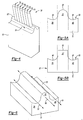
Figure 3 illustrates tool for forming a trench and corresponding cooling holes on the turbine blade. -
Figure 4 illustrates another view of the tool ofFigure 3 . -
Figure 5a illustrates a cross section of a body portion of the tool ofFigure 3 . -
Figure 5b illustrates a cross section of the body portion of another embodiment of the tool ofFigure 3 . -
Figure 6 illustrates the body portion of the tool ofFigure 3 . -
Figure 7 illustrates another view of the tool ofFigure 3 . -
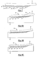
Figure 8a illustrates the tool ofFigure 3 forming a trench and cooling holes in a workpiece. -
Figure 8b illustrates another view of the tool ofFigure 3 forming the trench and cooling holes in the workpiece. -
Figure 8c illustrates another view of the tool ofFigure 3 forming the trench and cooling holes in the workpiece. -
Figure 1 illustrates aturbine blade 10 of a gas turbine engine. Theturbine blade 10 includes aroot portion 12, aplatform 14, and anairfoil 16. Atrench 18 is formed on a leadingedge 20 of theairfoil 16. A plurality ofcooling holes 22 extend from thetrench 18 to acavity 24 within the airfoil 16 (seeFig. 2 ). Thecooling holes 22 facilitate a flow of air from thecavity 24 to cool theairfoil 16. Thecooling holes 22 may also be referred to as "film holes" because they create a passage from thecavity 24 of theairfoil 16 to an air film on an outside of theairfoil 16. -
Figures 3 and4 illustrate atool 30 for forming thetrench 18 and thecooling holes 22 within thetrench 18. Thetool 30 includes abody portion 31 and a plurality ofelectrodes 34. Thebody portion 31 includes aridge portion 32, a first recessedportion 38, and a second recessedportion 40. Theridge portion 32 extends along afirst side 33 of thebody portion 31 of thetool 30. The plurality ofelectrodes 34 extend from theridge portion 32. - In the Example of
Figure 5a , theridge portion 32 has anarcuate cross section 44, the firstrecessed portion 38 has anarcuate cross section 46, and the secondrecessed portion 40 has anarcuate cross section 48. Therecessed portions ridge portion 32 and the arcuate cross sections form a continuous winding cross section of the body. However, other configurations would be possible. For example, as shown inFigure 5b , the ridge portion 32' may have aplanar cross section 45. - As shown in
Figure 6 , theridge portion 32 extends along anaxis 50, the firstrecessed portion 38 extends along anaxis 52, and the secondrecessed portion 40 extends along anaxis 54. In one example theaxes axis 50. Collectively, theridge portion 32, recessedportions electrodes 34 define an integral comb. As shown inFigures 4 and7 , the plurality ofelectrodes 34 may be parallel to each other such that the plurality ofcooling holes 22 are also parallel to each other. The plurality ofelectrodes 34 may extend from thebody portion 31 at an angle 60 (seeFig. 7 ). - The
ridge portion 32 andrecessed portions airfoil 16 of theturbine blade 10 to form thetrench 18, and theelectrodes 34 are operable to form the plurality ofcooling holes 22 in thetrench 18. In one example the tool is applied after theturbine blade 10 has been formed, heat treated, and left to harden for several days. Theridge portion 32 and plurality ofelectrodes 34 are at least partially composed of an electrically conductive metal (e.g. copper) such that an electrical current may flow from thetool 30 to theairfoil 16 of theturbine blade 10 to remove material from theturbine blade 10 to form thetrench 18 andcooling holes 22 in an electronic discharge machining ("EDM") process. - In an example EDM process, the tool is brought into close proximity to the
turbine blade 10 such that an electric arc is formed between one or more of theelectrodes 34 and theturbine blade 10. Once this arc is detected, a higher voltage may be applied to the tool to begin forming thecooling holes 22 in theairfoil portion 16 of the turbine blade. As shown inFigure 8a , thetool 30 may be applied to theturbine blade 10 at theangle 60 along anaxis 64 of one of the plurality ofelectrodes 34. InFigure 8a , thetool 30 is shown with the electrodes forming an initial portion of thecooling holes 22. InFigure 8b , theelectrodes 34 of thetool 30 have been inserted further into theairfoil 10 such that an additional portion of thecooling holes 22 has been formed. InFigure 8c , theelectrodes 34 of thetool 30 have been completely inserted into theturbine blade 10 such that thecooling holes 22 and the trench 18 (seeFigs. 1, 2 ) have been formed in their entirety. - Unlike the prior art, the
tool 30 is an integral comb such that asingle tool 30 may be used to create both thetrench 18 and the plurality ofcooling holes 22. In one example thetrench 18 and plurality ofcooling holes 22 may be created in a single application of thetool 30. It is no longer necessary to create atrench 18 with a first tool, and then to separately create thecooling holes 22 with a second tool, or conversely to create thecooling holes 22 with a first tool and then to create thetrench 18 connecting thecooling holes 22 with a second tool. Thetool 30 consistently createscooling holes 22 at desired locations within thetrench 18, reducing the cost of manufacturing a desired turbine blade and increasing reliability. By using thetool 30, issues of thetrench 18 not being properly aligned with thecooling holes 22 can be reduced or completely eliminated. - Although the
tool 30 has been described as forming atrench 18 and plurality ofcooling holes 22 in a turbine blade, it is understood that thetool 30 could be used on other non-turbine blade workpieces. For example, thetool 30 could be used to form atrench 18 and coolingholes 22 in a turbine vane. - Although an embodiment of this invention has been disclosed, a worker of ordinary skill in this art would recognize that certain modifications would come within the scope of this invention. For that reason, the following claims should be studied to determine the true scope and content of this invention.
Claims (15)
- A tool for forming a trench and a plurality of cooling holes within the trench, comprising:a body, the body comprising a ridge portion extending along a first side of the tool and being operable to mate with a workpiece to form a trench on the workpiece; anda plurality of electrodes extending from the ridge portion and being oriented to form a plurality of cooling holes within the trench on the workpiece.
- The tool of claim 1, wherein the ridge portion and plurality of electrodes are at least partially composed of an electrically conductive metal such that an electrical current may flow from the tool to the workpiece to remove material from the workpiece to form the trench and cooling holes in an electronic discharge machining process.
- The tool of claim 1, wherein the workpiece is an airfoil portion of a turbine blade for a gas turbine engine or an airfoil portion of a turbine vane for a gas turbine engine.
- The tool of claim 1, wherein the workpiece is a hollow airfoil having an inner cavity, the tool being such that the trench is formed along a leading edge of the airfoil and wherein the cooling holes define a plurality of passages from the trench to the inner cavity.
- The tool of claim 1, 2, 3 or 4 wherein the plurality of electrodes are parallel to each other.
- The tool of claim 1, 2, 3, 4 or 5, the body of the tool including:a first recessed portion extending along a first side of the ridge portion in a direction parallel to an axis of the ridge portion; anda second recessed portion extending along a second side, opposite the first side, of the ridge portion in a direction parallel to the axis of the ridge portion.
- The tool of claim 6, wherein the ridge portion has an arcuate cross section, the first recessed portion has an arcuate cross section, and the second recessed portion has an arcuate cross section, each of the arcuate cross sections forming a continuous winding cross section of the body.
- The tool of claim 6, wherein the ridge portion has a planar cross section, the first recessed portion has an arcuate cross section, and the second recessed portion has an arcuate cross section.
- The tool of claim 6, 7 or 8, wherein the ridge portion, the first recessed portion, the second recessed portion, and the plurality of electrodes collectively define an integral comb.
- A method of forming an airfoil having a trench and a plurality of holes within the trench, comprising:applying a plurality of electrodes extending from a tool to an airfoil;passing an electric current from the plurality of electrodes to the airfoil to remove material from the airfoil to form a plurality of holes in the airfoil;applying a ridge portion of the tool to the airfoil, the ridge portion extending along a first die of the tool, each of the plurality of electrodes extending from the ridge portion; andpassing an electric current from the ridge portion to the airfoil to remove material from the airfoil to form a trench along the airfoil, such that each of the plurality of holes are within the trench, and such that a single tool is used to form both the trench and the plurality of holes.
- The method of claim 10, wherein the plurality of electrodes and the ridge portion are applied to a leading edge of the airfoil.
- The method of claim 10 or 11, wherein the airfoil is an airfoil portion of a turbine blade for a gas turbine engine.
- The method of claim 10 or 11, wherein the airfoil is one of an airfoil portion of a turbine blade for a gas turbine engine or an airfoil portion of a turbine vane for a gas turbine engine.
- The method of claim 10 or 11, wherein the airfoil is a turbine blade for a gas turbine engine, and wherein said steps of applying a plurality of electrodes extending from a tool to a leading edge of an airfoil, passing an electric current from the plurality of electrodes to the airfoil, applying a ridge portion of the tool to the leading edge of the airfoil, and passing an electric current from the ridge portion to the airfoil are selectively repeated for each of a plurality turbine blades extending radially from a rotor of the gas turbine engine.
- The method of claim 10, 11, 12, 13 or 13 wherein the workpiece is a hollow airfoil having an inner cavity, and wherein the trench is formed along a leading edge of the airfoil and the plurality of holes define a plurality of passages from the trench to the inner cavity.
Applications Claiming Priority (1)
| Application Number | Priority Date | Filing Date | Title |
|---|---|---|---|
| US12/697,437 US8742279B2 (en) | 2010-02-01 | 2010-02-01 | Method of creating an airfoil trench and a plurality of cooling holes within the trench |
Publications (3)
| Publication Number | Publication Date |
|---|---|
| EP2359972A2 true EP2359972A2 (en) | 2011-08-24 |
| EP2359972A3 EP2359972A3 (en) | 2012-05-02 |
| EP2359972B1 EP2359972B1 (en) | 2018-01-24 |
Family
ID=44340710
Family Applications (1)
| Application Number | Title | Priority Date | Filing Date |
|---|---|---|---|
| EP11250110.1A Not-in-force EP2359972B1 (en) | 2010-02-01 | 2011-02-01 | Method of creating an airfoil trench and a plurality of cooling holes within the trench |
Country Status (2)
| Country | Link |
|---|---|
| US (1) | US8742279B2 (en) |
| EP (1) | EP2359972B1 (en) |
Cited By (3)
| Publication number | Priority date | Publication date | Assignee | Title |
|---|---|---|---|---|
| US8979442B2 (en) | 2012-05-16 | 2015-03-17 | Solar Turbines Incorporated | System and method for modifying a gas turbine engine in the field |
| US9441488B1 (en) | 2013-11-07 | 2016-09-13 | United States Of America As Represented By The Secretary Of The Air Force | Film cooling holes for gas turbine airfoils |
| CN111843081A (en) * | 2020-07-31 | 2020-10-30 | 成都和鸿科技有限公司 | Turbine blade exhaust edge air film hole machining method |
Families Citing this family (16)
| Publication number | Priority date | Publication date | Assignee | Title |
|---|---|---|---|---|
| US8742279B2 (en) * | 2010-02-01 | 2014-06-03 | United Technologies Corporation | Method of creating an airfoil trench and a plurality of cooling holes within the trench |
| US10364680B2 (en) | 2012-08-14 | 2019-07-30 | United Technologies Corporation | Gas turbine engine component having platform trench |
| US10655473B2 (en) | 2012-12-13 | 2020-05-19 | United Technologies Corporation | Gas turbine engine turbine blade leading edge tip trench cooling |
| EP2956627B1 (en) | 2013-02-15 | 2018-07-25 | United Technologies Corporation | Gas turbine engine component with combined mate face and platform cooling |
| WO2015047516A1 (en) * | 2013-07-03 | 2015-04-02 | General Electric Company | Trench cooling of airfoil structures |
| US10775115B2 (en) | 2013-08-29 | 2020-09-15 | General Electric Company | Thermal spray coating method and thermal spray coated article |
| EP3047105B1 (en) | 2013-09-17 | 2021-06-09 | Raytheon Technologies Corporation | Platform cooling core for a gas turbine engine rotor blade |
| US9878386B2 (en) * | 2013-10-31 | 2018-01-30 | Foundation Of Soongsil University-Industry Cooperation | Eccentric electrode for electric discharge machining, method of manufacturing the same, and micro electric discharge machining apparatus including the same |
| US10132167B2 (en) | 2014-06-16 | 2018-11-20 | United Technologies Corporation | Methods for creating a film cooled article for a gas turbine engine |
| US10376998B2 (en) * | 2014-07-03 | 2019-08-13 | United Technologies Corporation | Methods and tools for use in repairing gas engine turbine blades |
| CN104439637B (en) * | 2014-11-17 | 2016-08-17 | 句容五星机械制造有限公司 | A kind of blade of stirrer CO2welding procedure |
| US10697301B2 (en) * | 2017-04-07 | 2020-06-30 | General Electric Company | Turbine engine airfoil having a cooling circuit |
| EP3970893B1 (en) * | 2020-09-18 | 2025-01-08 | Ansaldo Energia Switzerland AG | Electrochemical machining electrode device for realizing a cooling slot in a blade of a gas turbine assembly and method for realizing a cooling slot in a blade of a gas turbine assembly using this electrochemical machining electrode device |
| CN112496485B (en) * | 2020-11-16 | 2022-08-09 | 中国航发沈阳黎明航空发动机有限责任公司 | Positioning fixture for machining air film hole in shielding part of duplex block-cast guide blade and machining method of air film hole |
| US12350750B2 (en) | 2022-06-17 | 2025-07-08 | General Electric Company | Methods and systems of electrochemical machining |
| US12320029B2 (en) | 2022-06-17 | 2025-06-03 | General Electric Company | Methods and systems of electrochemical machining |
Family Cites Families (31)
| Publication number | Priority date | Publication date | Assignee | Title |
|---|---|---|---|---|
| GB1209692A (en) * | 1968-05-14 | 1970-10-21 | Rolls Royce | Method and apparatus for the spark-machining of workpieces and a spark-machining electrode for use therein |
| US4197443A (en) | 1977-09-19 | 1980-04-08 | General Electric Company | Method and apparatus for forming diffused cooling holes in an airfoil |
| US4441004A (en) * | 1980-06-12 | 1984-04-03 | Inoue-Japax Research Incorporated | Multiple pipe element electrode assembly EDM method and apparatus |
| US4664597A (en) | 1985-12-23 | 1987-05-12 | United Technologies Corporation | Coolant passages with full coverage film cooling slot |
| US4684323A (en) * | 1985-12-23 | 1987-08-04 | United Technologies Corporation | Film cooling passages with curved corners |
| US4738588A (en) | 1985-12-23 | 1988-04-19 | Field Robert E | Film cooling passages with step diffuser |
| US4650949A (en) * | 1985-12-23 | 1987-03-17 | United Technologies Corporation | Electrode for electrical discharge machining film cooling passages in an airfoil |
| US4762464A (en) * | 1986-11-13 | 1988-08-09 | Chromalloy Gas Turbine Corporation | Airfoil with diffused cooling holes and method and apparatus for making the same |
| US4819325A (en) * | 1987-06-01 | 1989-04-11 | Technical Manufacturing Systems, Inc. | Method of forming electro-discharge machining electrode |
| US4922076A (en) * | 1987-06-01 | 1990-05-01 | Technical Manufacturing Systems, Inc. | Electro-discharge machining electrode |
| US5690473A (en) | 1992-08-25 | 1997-11-25 | General Electric Company | Turbine blade having transpiration strip cooling and method of manufacture |
| US5605639A (en) * | 1993-12-21 | 1997-02-25 | United Technologies Corporation | Method of producing diffusion holes in turbine components by a multiple piece electrode |
| US5637239A (en) * | 1995-03-31 | 1997-06-10 | United Technologies Corporation | Curved electrode and method for electrical discharge machining curved cooling holes |
| US5779437A (en) | 1996-10-31 | 1998-07-14 | Pratt & Whitney Canada Inc. | Cooling passages for airfoil leading edge |
| US6050777A (en) | 1997-12-17 | 2000-04-18 | United Technologies Corporation | Apparatus and method for cooling an airfoil for a gas turbine engine |
| EP0945593B1 (en) | 1998-03-23 | 2003-05-07 | ALSTOM (Switzerland) Ltd | Film-cooling hole |
| US6164912A (en) | 1998-12-21 | 2000-12-26 | United Technologies Corporation | Hollow airfoil for a gas turbine engine |
| US6310312B1 (en) * | 1999-07-02 | 2001-10-30 | United Technologies Corporation | Method and apparatus for testing electrodes in an EDM process |
| US7204019B2 (en) * | 2001-08-23 | 2007-04-17 | United Technologies Corporation | Method for repairing an apertured gas turbine component |
| US6791054B1 (en) * | 2003-07-31 | 2004-09-14 | General Electric Company | Electrode holding and dispensing assembly for electrical discharge machining apparatus |
| US7300252B2 (en) | 2004-10-04 | 2007-11-27 | Alstom Technology Ltd | Gas turbine airfoil leading edge cooling construction |
| US7134475B2 (en) * | 2004-10-29 | 2006-11-14 | United Technologies Corporation | Investment casting cores and methods |
| US7220934B2 (en) * | 2005-06-07 | 2007-05-22 | United Technologies Corporation | Method of producing cooling holes in highly contoured airfoils |
| US20070034524A1 (en) | 2005-08-12 | 2007-02-15 | United Technologies Corporation | Masking techniques for electrochemical stripping |
| US7322796B2 (en) * | 2005-08-31 | 2008-01-29 | United Technologies Corporation | Turbine vane construction |
| US7618514B2 (en) * | 2006-02-03 | 2009-11-17 | United Technologies Corporation | Photo-etched EDM electrode |
| US7291800B2 (en) * | 2006-02-23 | 2007-11-06 | United Technologies Corporation | EDM electrode tool holder |
| US7563073B1 (en) * | 2006-10-10 | 2009-07-21 | Florida Turbine Technologies, Inc. | Turbine blade with film cooling slot |
| US8245519B1 (en) * | 2008-11-25 | 2012-08-21 | Florida Turbine Technologies, Inc. | Laser shaped film cooling hole |
| US8168912B1 (en) * | 2009-02-19 | 2012-05-01 | Florida Turbine Technologies, Inc. | Electrode for shaped film cooling hole |
| US8742279B2 (en) * | 2010-02-01 | 2014-06-03 | United Technologies Corporation | Method of creating an airfoil trench and a plurality of cooling holes within the trench |
-
2010
- 2010-02-01 US US12/697,437 patent/US8742279B2/en active Active
-
2011
- 2011-02-01 EP EP11250110.1A patent/EP2359972B1/en not_active Not-in-force
Non-Patent Citations (1)
| Title |
|---|
| None |
Cited By (4)
| Publication number | Priority date | Publication date | Assignee | Title |
|---|---|---|---|---|
| US8979442B2 (en) | 2012-05-16 | 2015-03-17 | Solar Turbines Incorporated | System and method for modifying a gas turbine engine in the field |
| US9441488B1 (en) | 2013-11-07 | 2016-09-13 | United States Of America As Represented By The Secretary Of The Air Force | Film cooling holes for gas turbine airfoils |
| CN111843081A (en) * | 2020-07-31 | 2020-10-30 | 成都和鸿科技有限公司 | Turbine blade exhaust edge air film hole machining method |
| CN111843081B (en) * | 2020-07-31 | 2021-05-11 | 成都和鸿科技有限公司 | Turbine blade exhaust edge air film hole machining method |
Also Published As
| Publication number | Publication date |
|---|---|
| EP2359972A3 (en) | 2012-05-02 |
| US20110186550A1 (en) | 2011-08-04 |
| EP2359972B1 (en) | 2018-01-24 |
| US8742279B2 (en) | 2014-06-03 |
Similar Documents
| Publication | Publication Date | Title |
|---|---|---|
| EP2359972B1 (en) | Method of creating an airfoil trench and a plurality of cooling holes within the trench | |
| JP5837927B2 (en) | Solid phase resistance welding to repair and fabricate airfoils | |
| US8978249B2 (en) | Methods for repairing a gas turbine component | |
| US8302668B1 (en) | Hybrid core assembly for a casting process | |
| EP2022586B1 (en) | Method for forming cooling holes having circular inlets and non-circular outlets | |
| US9441497B2 (en) | Combined featherseal slot and lightening pocket | |
| EP2971519B1 (en) | Method for working airfoil clusters of a gas turbine engine | |
| RU2666715C2 (en) | Turbomachine component with stress relief cavity | |
| US10487660B2 (en) | Additively manufactured blade extension with internal features | |
| JP6156326B2 (en) | END PLATE FOR FUEL CELL, MANUFACTURING METHOD THEREOF, AND FUEL CELL | |
| JP2015527529A (en) | Template for forming cooling passages in turbine engine components | |
| JP2013255989A (en) | Electrode and electrochemical machining process for forming non-circular holes | |
| KR100694750B1 (en) | How to Create Cooling Holes in Highly Shaped Airfoils | |
| US20180347368A1 (en) | Airfoil and method of fabricating same | |
| EP3060703B1 (en) | Method for creating airfoil leading and trailing edges | |
| KR20230048601A (en) | Backwall strike braze repair | |
| EP2674510B1 (en) | Channel marker and related methods | |
| CN104588803A (en) | method for manufacturing a microchannel in surface of machine component |
Legal Events
| Date | Code | Title | Description |
|---|---|---|---|
| PUAI | Public reference made under article 153(3) epc to a published international application that has entered the european phase |
Free format text: ORIGINAL CODE: 0009012 |
|
| AK | Designated contracting states |
Kind code of ref document: A2 Designated state(s): AL AT BE BG CH CY CZ DE DK EE ES FI FR GB GR HR HU IE IS IT LI LT LU LV MC MK MT NL NO PL PT RO RS SE SI SK SM TR |
|
| AX | Request for extension of the european patent |
Extension state: BA ME |
|
| PUAL | Search report despatched |
Free format text: ORIGINAL CODE: 0009013 |
|
| AK | Designated contracting states |
Kind code of ref document: A3 Designated state(s): AL AT BE BG CH CY CZ DE DK EE ES FI FR GB GR HR HU IE IS IT LI LT LU LV MC MK MT NL NO PL PT RO RS SE SI SK SM TR |
|
| AX | Request for extension of the european patent |
Extension state: BA ME |
|
| RIC1 | Information provided on ipc code assigned before grant |
Ipc: B23H 9/14 20060101ALI20120323BHEP Ipc: B23H 1/04 20060101AFI20120323BHEP Ipc: B23H 9/10 20060101ALI20120323BHEP |
|
| 17P | Request for examination filed |
Effective date: 20121102 |
|
| RAP1 | Party data changed (applicant data changed or rights of an application transferred) |
Owner name: UNITED TECHNOLOGIES CORPORATION |
|
| GRAP | Despatch of communication of intention to grant a patent |
Free format text: ORIGINAL CODE: EPIDOSNIGR1 |
|
| STAA | Information on the status of an ep patent application or granted ep patent |
Free format text: STATUS: GRANT OF PATENT IS INTENDED |
|
| INTG | Intention to grant announced |
Effective date: 20170927 |
|
| RIN1 | Information on inventor provided before grant (corrected) |
Inventor name: GANNELLI, JESSE Inventor name: PIETRASZKIEWICZ, EDWARD F. Inventor name: LEVY, RYAN SHEPARD Inventor name: GAYMAN, SCOTT W. Inventor name: PINERO, SANDRA S. Inventor name: JELKS, CHRISTOPHER B. Inventor name: REMBISH, PAUL THOMAS |
|
| GRAS | Grant fee paid |
Free format text: ORIGINAL CODE: EPIDOSNIGR3 |
|
| GRAA | (expected) grant |
Free format text: ORIGINAL CODE: 0009210 |
|
| STAA | Information on the status of an ep patent application or granted ep patent |
Free format text: STATUS: THE PATENT HAS BEEN GRANTED |
|
| AK | Designated contracting states |
Kind code of ref document: B1 Designated state(s): AL AT BE BG CH CY CZ DE DK EE ES FI FR GB GR HR HU IE IS IT LI LT LU LV MC MK MT NL NO PL PT RO RS SE SI SK SM TR |
|
| REG | Reference to a national code |
Ref country code: GB Ref legal event code: FG4D |
|
| REG | Reference to a national code |
Ref country code: CH Ref legal event code: EP |
|
| REG | Reference to a national code |
Ref country code: AT Ref legal event code: REF Ref document number: 965510 Country of ref document: AT Kind code of ref document: T Effective date: 20180215 |
|
| REG | Reference to a national code |
Ref country code: FR Ref legal event code: PLFP Year of fee payment: 8 |
|
| REG | Reference to a national code |
Ref country code: IE Ref legal event code: FG4D |
|
| REG | Reference to a national code |
Ref country code: DE Ref legal event code: R096 Ref document number: 602011045253 Country of ref document: DE |
|
| REG | Reference to a national code |
Ref country code: NL Ref legal event code: MP Effective date: 20180124 |
|
| REG | Reference to a national code |
Ref country code: LT Ref legal event code: MG4D |
|
| REG | Reference to a national code |
Ref country code: AT Ref legal event code: MK05 Ref document number: 965510 Country of ref document: AT Kind code of ref document: T Effective date: 20180124 |
|
| PG25 | Lapsed in a contracting state [announced via postgrant information from national office to epo] |
Ref country code: NL Free format text: LAPSE BECAUSE OF FAILURE TO SUBMIT A TRANSLATION OF THE DESCRIPTION OR TO PAY THE FEE WITHIN THE PRESCRIBED TIME-LIMIT Effective date: 20180124 |
|
| PG25 | Lapsed in a contracting state [announced via postgrant information from national office to epo] |
Ref country code: CY Free format text: LAPSE BECAUSE OF FAILURE TO SUBMIT A TRANSLATION OF THE DESCRIPTION OR TO PAY THE FEE WITHIN THE PRESCRIBED TIME-LIMIT Effective date: 20180124 Ref country code: ES Free format text: LAPSE BECAUSE OF FAILURE TO SUBMIT A TRANSLATION OF THE DESCRIPTION OR TO PAY THE FEE WITHIN THE PRESCRIBED TIME-LIMIT Effective date: 20180124 Ref country code: LT Free format text: LAPSE BECAUSE OF FAILURE TO SUBMIT A TRANSLATION OF THE DESCRIPTION OR TO PAY THE FEE WITHIN THE PRESCRIBED TIME-LIMIT Effective date: 20180124 Ref country code: HR Free format text: LAPSE BECAUSE OF FAILURE TO SUBMIT A TRANSLATION OF THE DESCRIPTION OR TO PAY THE FEE WITHIN THE PRESCRIBED TIME-LIMIT Effective date: 20180124 Ref country code: NO Free format text: LAPSE BECAUSE OF FAILURE TO SUBMIT A TRANSLATION OF THE DESCRIPTION OR TO PAY THE FEE WITHIN THE PRESCRIBED TIME-LIMIT Effective date: 20180424 Ref country code: FI Free format text: LAPSE BECAUSE OF FAILURE TO SUBMIT A TRANSLATION OF THE DESCRIPTION OR TO PAY THE FEE WITHIN THE PRESCRIBED TIME-LIMIT Effective date: 20180124 |
|
| PG25 | Lapsed in a contracting state [announced via postgrant information from national office to epo] |
Ref country code: LV Free format text: LAPSE BECAUSE OF FAILURE TO SUBMIT A TRANSLATION OF THE DESCRIPTION OR TO PAY THE FEE WITHIN THE PRESCRIBED TIME-LIMIT Effective date: 20180124 Ref country code: SE Free format text: LAPSE BECAUSE OF FAILURE TO SUBMIT A TRANSLATION OF THE DESCRIPTION OR TO PAY THE FEE WITHIN THE PRESCRIBED TIME-LIMIT Effective date: 20180124 Ref country code: PL Free format text: LAPSE BECAUSE OF FAILURE TO SUBMIT A TRANSLATION OF THE DESCRIPTION OR TO PAY THE FEE WITHIN THE PRESCRIBED TIME-LIMIT Effective date: 20180124 Ref country code: BG Free format text: LAPSE BECAUSE OF FAILURE TO SUBMIT A TRANSLATION OF THE DESCRIPTION OR TO PAY THE FEE WITHIN THE PRESCRIBED TIME-LIMIT Effective date: 20180424 Ref country code: GR Free format text: LAPSE BECAUSE OF FAILURE TO SUBMIT A TRANSLATION OF THE DESCRIPTION OR TO PAY THE FEE WITHIN THE PRESCRIBED TIME-LIMIT Effective date: 20180425 Ref country code: IS Free format text: LAPSE BECAUSE OF FAILURE TO SUBMIT A TRANSLATION OF THE DESCRIPTION OR TO PAY THE FEE WITHIN THE PRESCRIBED TIME-LIMIT Effective date: 20180524 Ref country code: RS Free format text: LAPSE BECAUSE OF FAILURE TO SUBMIT A TRANSLATION OF THE DESCRIPTION OR TO PAY THE FEE WITHIN THE PRESCRIBED TIME-LIMIT Effective date: 20180124 Ref country code: AT Free format text: LAPSE BECAUSE OF FAILURE TO SUBMIT A TRANSLATION OF THE DESCRIPTION OR TO PAY THE FEE WITHIN THE PRESCRIBED TIME-LIMIT Effective date: 20180124 |
|
| REG | Reference to a national code |
Ref country code: CH Ref legal event code: PL |
|
| REG | Reference to a national code |
Ref country code: DE Ref legal event code: R097 Ref document number: 602011045253 Country of ref document: DE |
|
| PG25 | Lapsed in a contracting state [announced via postgrant information from national office to epo] |
Ref country code: IT Free format text: LAPSE BECAUSE OF FAILURE TO SUBMIT A TRANSLATION OF THE DESCRIPTION OR TO PAY THE FEE WITHIN THE PRESCRIBED TIME-LIMIT Effective date: 20180124 Ref country code: MC Free format text: LAPSE BECAUSE OF FAILURE TO SUBMIT A TRANSLATION OF THE DESCRIPTION OR TO PAY THE FEE WITHIN THE PRESCRIBED TIME-LIMIT Effective date: 20180124 Ref country code: AL Free format text: LAPSE BECAUSE OF FAILURE TO SUBMIT A TRANSLATION OF THE DESCRIPTION OR TO PAY THE FEE WITHIN THE PRESCRIBED TIME-LIMIT Effective date: 20180124 Ref country code: EE Free format text: LAPSE BECAUSE OF FAILURE TO SUBMIT A TRANSLATION OF THE DESCRIPTION OR TO PAY THE FEE WITHIN THE PRESCRIBED TIME-LIMIT Effective date: 20180124 Ref country code: RO Free format text: LAPSE BECAUSE OF FAILURE TO SUBMIT A TRANSLATION OF THE DESCRIPTION OR TO PAY THE FEE WITHIN THE PRESCRIBED TIME-LIMIT Effective date: 20180124 |
|
| REG | Reference to a national code |
Ref country code: IE Ref legal event code: MM4A |
|
| REG | Reference to a national code |
Ref country code: BE Ref legal event code: MM Effective date: 20180228 |
|
| PG25 | Lapsed in a contracting state [announced via postgrant information from national office to epo] |
Ref country code: SM Free format text: LAPSE BECAUSE OF FAILURE TO SUBMIT A TRANSLATION OF THE DESCRIPTION OR TO PAY THE FEE WITHIN THE PRESCRIBED TIME-LIMIT Effective date: 20180124 Ref country code: LU Free format text: LAPSE BECAUSE OF NON-PAYMENT OF DUE FEES Effective date: 20180201 Ref country code: CZ Free format text: LAPSE BECAUSE OF FAILURE TO SUBMIT A TRANSLATION OF THE DESCRIPTION OR TO PAY THE FEE WITHIN THE PRESCRIBED TIME-LIMIT Effective date: 20180124 Ref country code: DK Free format text: LAPSE BECAUSE OF FAILURE TO SUBMIT A TRANSLATION OF THE DESCRIPTION OR TO PAY THE FEE WITHIN THE PRESCRIBED TIME-LIMIT Effective date: 20180124 Ref country code: SK Free format text: LAPSE BECAUSE OF FAILURE TO SUBMIT A TRANSLATION OF THE DESCRIPTION OR TO PAY THE FEE WITHIN THE PRESCRIBED TIME-LIMIT Effective date: 20180124 Ref country code: CH Free format text: LAPSE BECAUSE OF NON-PAYMENT OF DUE FEES Effective date: 20180228 Ref country code: LI Free format text: LAPSE BECAUSE OF NON-PAYMENT OF DUE FEES Effective date: 20180228 |
|
| PLBE | No opposition filed within time limit |
Free format text: ORIGINAL CODE: 0009261 |
|
| STAA | Information on the status of an ep patent application or granted ep patent |
Free format text: STATUS: NO OPPOSITION FILED WITHIN TIME LIMIT |
|
| 26N | No opposition filed |
Effective date: 20181025 |
|
| PG25 | Lapsed in a contracting state [announced via postgrant information from national office to epo] |
Ref country code: IE Free format text: LAPSE BECAUSE OF NON-PAYMENT OF DUE FEES Effective date: 20180201 |
|
| PG25 | Lapsed in a contracting state [announced via postgrant information from national office to epo] |
Ref country code: BE Free format text: LAPSE BECAUSE OF NON-PAYMENT OF DUE FEES Effective date: 20180228 Ref country code: SI Free format text: LAPSE BECAUSE OF FAILURE TO SUBMIT A TRANSLATION OF THE DESCRIPTION OR TO PAY THE FEE WITHIN THE PRESCRIBED TIME-LIMIT Effective date: 20180124 |
|
| PG25 | Lapsed in a contracting state [announced via postgrant information from national office to epo] |
Ref country code: MT Free format text: LAPSE BECAUSE OF NON-PAYMENT OF DUE FEES Effective date: 20180201 |
|
| PG25 | Lapsed in a contracting state [announced via postgrant information from national office to epo] |
Ref country code: TR Free format text: LAPSE BECAUSE OF FAILURE TO SUBMIT A TRANSLATION OF THE DESCRIPTION OR TO PAY THE FEE WITHIN THE PRESCRIBED TIME-LIMIT Effective date: 20180124 |
|
| PG25 | Lapsed in a contracting state [announced via postgrant information from national office to epo] |
Ref country code: HU Free format text: LAPSE BECAUSE OF FAILURE TO SUBMIT A TRANSLATION OF THE DESCRIPTION OR TO PAY THE FEE WITHIN THE PRESCRIBED TIME-LIMIT; INVALID AB INITIO Effective date: 20110201 Ref country code: PT Free format text: LAPSE BECAUSE OF FAILURE TO SUBMIT A TRANSLATION OF THE DESCRIPTION OR TO PAY THE FEE WITHIN THE PRESCRIBED TIME-LIMIT Effective date: 20180124 |
|
| PG25 | Lapsed in a contracting state [announced via postgrant information from national office to epo] |
Ref country code: MK Free format text: LAPSE BECAUSE OF NON-PAYMENT OF DUE FEES Effective date: 20180124 |
|
| REG | Reference to a national code |
Ref country code: DE Ref legal event code: R081 Ref document number: 602011045253 Country of ref document: DE Owner name: RAYTHEON TECHNOLOGIES CORPORATION (N.D.GES.D.S, US Free format text: FORMER OWNER: UNITED TECHNOLOGIES CORPORATION, FARMINGTON, CONN., US |
|
| P01 | Opt-out of the competence of the unified patent court (upc) registered |
Effective date: 20230520 |
|
| PGFP | Annual fee paid to national office [announced via postgrant information from national office to epo] |
Ref country code: DE Payment date: 20240123 Year of fee payment: 14 Ref country code: GB Payment date: 20240123 Year of fee payment: 14 |
|
| PGFP | Annual fee paid to national office [announced via postgrant information from national office to epo] |
Ref country code: FR Payment date: 20240123 Year of fee payment: 14 |
|
| REG | Reference to a national code |
Ref country code: DE Ref legal event code: R119 Ref document number: 602011045253 Country of ref document: DE |
|
| GBPC | Gb: european patent ceased through non-payment of renewal fee |
Effective date: 20250201 |
|
| PG25 | Lapsed in a contracting state [announced via postgrant information from national office to epo] |
Ref country code: DE Free format text: LAPSE BECAUSE OF NON-PAYMENT OF DUE FEES Effective date: 20250902 |
|
| PG25 | Lapsed in a contracting state [announced via postgrant information from national office to epo] |
Ref country code: GB Free format text: LAPSE BECAUSE OF NON-PAYMENT OF DUE FEES Effective date: 20250201 |
|
| PG25 | Lapsed in a contracting state [announced via postgrant information from national office to epo] |
Ref country code: FR Free format text: LAPSE BECAUSE OF NON-PAYMENT OF DUE FEES Effective date: 20250228 |