EP2359786A1 - Method of manufacturing absorptive article - Google Patents
Method of manufacturing absorptive article Download PDFInfo
- Publication number
- EP2359786A1 EP2359786A1 EP09826101A EP09826101A EP2359786A1 EP 2359786 A1 EP2359786 A1 EP 2359786A1 EP 09826101 A EP09826101 A EP 09826101A EP 09826101 A EP09826101 A EP 09826101A EP 2359786 A1 EP2359786 A1 EP 2359786A1
- Authority
- EP
- European Patent Office
- Prior art keywords
- ultrasonic
- web
- absorbent article
- output
- regions
- Prior art date
- Legal status (The legal status is an assumption and is not a legal conclusion. Google has not performed a legal analysis and makes no representation as to the accuracy of the status listed.)
- Granted
Links
Images






Classifications
-
- B—PERFORMING OPERATIONS; TRANSPORTING
- B29—WORKING OF PLASTICS; WORKING OF SUBSTANCES IN A PLASTIC STATE IN GENERAL
- B29C—SHAPING OR JOINING OF PLASTICS; SHAPING OF MATERIAL IN A PLASTIC STATE, NOT OTHERWISE PROVIDED FOR; AFTER-TREATMENT OF THE SHAPED PRODUCTS, e.g. REPAIRING
- B29C65/00—Joining or sealing of preformed parts, e.g. welding of plastics materials; Apparatus therefor
- B29C65/02—Joining or sealing of preformed parts, e.g. welding of plastics materials; Apparatus therefor by heating, with or without pressure
- B29C65/08—Joining or sealing of preformed parts, e.g. welding of plastics materials; Apparatus therefor by heating, with or without pressure using ultrasonic vibrations
-
- A—HUMAN NECESSITIES
- A61—MEDICAL OR VETERINARY SCIENCE; HYGIENE
- A61F—FILTERS IMPLANTABLE INTO BLOOD VESSELS; PROSTHESES; DEVICES PROVIDING PATENCY TO, OR PREVENTING COLLAPSING OF, TUBULAR STRUCTURES OF THE BODY, e.g. STENTS; ORTHOPAEDIC, NURSING OR CONTRACEPTIVE DEVICES; FOMENTATION; TREATMENT OR PROTECTION OF EYES OR EARS; BANDAGES, DRESSINGS OR ABSORBENT PADS; FIRST-AID KITS
- A61F13/00—Bandages or dressings; Absorbent pads
- A61F13/15—Absorbent pads, e.g. sanitary towels, swabs or tampons for external or internal application to the body; Supporting or fastening means therefor; Tampon applicators
- A61F13/15577—Apparatus or processes for manufacturing
- A61F13/15772—Control
-
- A—HUMAN NECESSITIES
- A61—MEDICAL OR VETERINARY SCIENCE; HYGIENE
- A61F—FILTERS IMPLANTABLE INTO BLOOD VESSELS; PROSTHESES; DEVICES PROVIDING PATENCY TO, OR PREVENTING COLLAPSING OF, TUBULAR STRUCTURES OF THE BODY, e.g. STENTS; ORTHOPAEDIC, NURSING OR CONTRACEPTIVE DEVICES; FOMENTATION; TREATMENT OR PROTECTION OF EYES OR EARS; BANDAGES, DRESSINGS OR ABSORBENT PADS; FIRST-AID KITS
- A61F13/00—Bandages or dressings; Absorbent pads
- A61F13/15—Absorbent pads, e.g. sanitary towels, swabs or tampons for external or internal application to the body; Supporting or fastening means therefor; Tampon applicators
- A61F13/15577—Apparatus or processes for manufacturing
- A61F13/15699—Forming webs by bringing together several webs, e.g. by laminating or folding several webs, with or without additional treatment of the webs
-
- A—HUMAN NECESSITIES
- A61—MEDICAL OR VETERINARY SCIENCE; HYGIENE
- A61F—FILTERS IMPLANTABLE INTO BLOOD VESSELS; PROSTHESES; DEVICES PROVIDING PATENCY TO, OR PREVENTING COLLAPSING OF, TUBULAR STRUCTURES OF THE BODY, e.g. STENTS; ORTHOPAEDIC, NURSING OR CONTRACEPTIVE DEVICES; FOMENTATION; TREATMENT OR PROTECTION OF EYES OR EARS; BANDAGES, DRESSINGS OR ABSORBENT PADS; FIRST-AID KITS
- A61F13/00—Bandages or dressings; Absorbent pads
- A61F13/15—Absorbent pads, e.g. sanitary towels, swabs or tampons for external or internal application to the body; Supporting or fastening means therefor; Tampon applicators
- A61F13/45—Absorbent pads, e.g. sanitary towels, swabs or tampons for external or internal application to the body; Supporting or fastening means therefor; Tampon applicators characterised by the shape
- A61F13/49—Absorbent pads, e.g. sanitary towels, swabs or tampons for external or internal application to the body; Supporting or fastening means therefor; Tampon applicators characterised by the shape specially adapted to be worn around the waist, e.g. diapers, nappies
-
- B—PERFORMING OPERATIONS; TRANSPORTING
- B29—WORKING OF PLASTICS; WORKING OF SUBSTANCES IN A PLASTIC STATE IN GENERAL
- B29C—SHAPING OR JOINING OF PLASTICS; SHAPING OF MATERIAL IN A PLASTIC STATE, NOT OTHERWISE PROVIDED FOR; AFTER-TREATMENT OF THE SHAPED PRODUCTS, e.g. REPAIRING
- B29C65/00—Joining or sealing of preformed parts, e.g. welding of plastics materials; Apparatus therefor
- B29C65/02—Joining or sealing of preformed parts, e.g. welding of plastics materials; Apparatus therefor by heating, with or without pressure
- B29C65/08—Joining or sealing of preformed parts, e.g. welding of plastics materials; Apparatus therefor by heating, with or without pressure using ultrasonic vibrations
- B29C65/083—Joining or sealing of preformed parts, e.g. welding of plastics materials; Apparatus therefor by heating, with or without pressure using ultrasonic vibrations using a rotary sonotrode or a rotary anvil
- B29C65/086—Joining or sealing of preformed parts, e.g. welding of plastics materials; Apparatus therefor by heating, with or without pressure using ultrasonic vibrations using a rotary sonotrode or a rotary anvil using a rotary anvil
-
- B—PERFORMING OPERATIONS; TRANSPORTING
- B29—WORKING OF PLASTICS; WORKING OF SUBSTANCES IN A PLASTIC STATE IN GENERAL
- B29C—SHAPING OR JOINING OF PLASTICS; SHAPING OF MATERIAL IN A PLASTIC STATE, NOT OTHERWISE PROVIDED FOR; AFTER-TREATMENT OF THE SHAPED PRODUCTS, e.g. REPAIRING
- B29C66/00—General aspects of processes or apparatus for joining preformed parts
- B29C66/01—General aspects dealing with the joint area or with the area to be joined
- B29C66/05—Particular design of joint configurations
- B29C66/10—Particular design of joint configurations particular design of the joint cross-sections
- B29C66/11—Joint cross-sections comprising a single joint-segment, i.e. one of the parts to be joined comprising a single joint-segment in the joint cross-section
- B29C66/112—Single lapped joints
- B29C66/1122—Single lap to lap joints, i.e. overlap joints
-
- B—PERFORMING OPERATIONS; TRANSPORTING
- B29—WORKING OF PLASTICS; WORKING OF SUBSTANCES IN A PLASTIC STATE IN GENERAL
- B29C—SHAPING OR JOINING OF PLASTICS; SHAPING OF MATERIAL IN A PLASTIC STATE, NOT OTHERWISE PROVIDED FOR; AFTER-TREATMENT OF THE SHAPED PRODUCTS, e.g. REPAIRING
- B29C66/00—General aspects of processes or apparatus for joining preformed parts
- B29C66/01—General aspects dealing with the joint area or with the area to be joined
- B29C66/05—Particular design of joint configurations
- B29C66/20—Particular design of joint configurations particular design of the joint lines, e.g. of the weld lines
- B29C66/21—Particular design of joint configurations particular design of the joint lines, e.g. of the weld lines said joint lines being formed by a single dot or dash or by several dots or dashes, i.e. spot joining or spot welding
-
- B—PERFORMING OPERATIONS; TRANSPORTING
- B29—WORKING OF PLASTICS; WORKING OF SUBSTANCES IN A PLASTIC STATE IN GENERAL
- B29C—SHAPING OR JOINING OF PLASTICS; SHAPING OF MATERIAL IN A PLASTIC STATE, NOT OTHERWISE PROVIDED FOR; AFTER-TREATMENT OF THE SHAPED PRODUCTS, e.g. REPAIRING
- B29C66/00—General aspects of processes or apparatus for joining preformed parts
- B29C66/01—General aspects dealing with the joint area or with the area to be joined
- B29C66/05—Particular design of joint configurations
- B29C66/20—Particular design of joint configurations particular design of the joint lines, e.g. of the weld lines
- B29C66/23—Particular design of joint configurations particular design of the joint lines, e.g. of the weld lines said joint lines being multiple and parallel or being in the form of tessellations
- B29C66/232—Particular design of joint configurations particular design of the joint lines, e.g. of the weld lines said joint lines being multiple and parallel or being in the form of tessellations said joint lines being multiple and parallel, i.e. the joint being formed by several parallel joint lines
-
- B—PERFORMING OPERATIONS; TRANSPORTING
- B29—WORKING OF PLASTICS; WORKING OF SUBSTANCES IN A PLASTIC STATE IN GENERAL
- B29C—SHAPING OR JOINING OF PLASTICS; SHAPING OF MATERIAL IN A PLASTIC STATE, NOT OTHERWISE PROVIDED FOR; AFTER-TREATMENT OF THE SHAPED PRODUCTS, e.g. REPAIRING
- B29C66/00—General aspects of processes or apparatus for joining preformed parts
- B29C66/40—General aspects of joining substantially flat articles, e.g. plates, sheets or web-like materials; Making flat seams in tubular or hollow articles; Joining single elements to substantially flat surfaces
- B29C66/41—Joining substantially flat articles ; Making flat seams in tubular or hollow articles
- B29C66/43—Joining a relatively small portion of the surface of said articles
- B29C66/431—Joining the articles to themselves
-
- B—PERFORMING OPERATIONS; TRANSPORTING
- B29—WORKING OF PLASTICS; WORKING OF SUBSTANCES IN A PLASTIC STATE IN GENERAL
- B29C—SHAPING OR JOINING OF PLASTICS; SHAPING OF MATERIAL IN A PLASTIC STATE, NOT OTHERWISE PROVIDED FOR; AFTER-TREATMENT OF THE SHAPED PRODUCTS, e.g. REPAIRING
- B29C66/00—General aspects of processes or apparatus for joining preformed parts
- B29C66/80—General aspects of machine operations or constructions and parts thereof
- B29C66/81—General aspects of the pressing elements, i.e. the elements applying pressure on the parts to be joined in the area to be joined, e.g. the welding jaws or clamps
- B29C66/814—General aspects of the pressing elements, i.e. the elements applying pressure on the parts to be joined in the area to be joined, e.g. the welding jaws or clamps characterised by the design of the pressing elements, e.g. of the welding jaws or clamps
- B29C66/8141—General aspects of the pressing elements, i.e. the elements applying pressure on the parts to be joined in the area to be joined, e.g. the welding jaws or clamps characterised by the design of the pressing elements, e.g. of the welding jaws or clamps characterised by the surface geometry of the part of the pressing elements, e.g. welding jaws or clamps, coming into contact with the parts to be joined
- B29C66/81427—General aspects of the pressing elements, i.e. the elements applying pressure on the parts to be joined in the area to be joined, e.g. the welding jaws or clamps characterised by the design of the pressing elements, e.g. of the welding jaws or clamps characterised by the surface geometry of the part of the pressing elements, e.g. welding jaws or clamps, coming into contact with the parts to be joined comprising a single ridge, e.g. for making a weakening line; comprising a single tooth
-
- B—PERFORMING OPERATIONS; TRANSPORTING
- B29—WORKING OF PLASTICS; WORKING OF SUBSTANCES IN A PLASTIC STATE IN GENERAL
- B29C—SHAPING OR JOINING OF PLASTICS; SHAPING OF MATERIAL IN A PLASTIC STATE, NOT OTHERWISE PROVIDED FOR; AFTER-TREATMENT OF THE SHAPED PRODUCTS, e.g. REPAIRING
- B29C66/00—General aspects of processes or apparatus for joining preformed parts
- B29C66/80—General aspects of machine operations or constructions and parts thereof
- B29C66/81—General aspects of the pressing elements, i.e. the elements applying pressure on the parts to be joined in the area to be joined, e.g. the welding jaws or clamps
- B29C66/814—General aspects of the pressing elements, i.e. the elements applying pressure on the parts to be joined in the area to be joined, e.g. the welding jaws or clamps characterised by the design of the pressing elements, e.g. of the welding jaws or clamps
- B29C66/8145—General aspects of the pressing elements, i.e. the elements applying pressure on the parts to be joined in the area to be joined, e.g. the welding jaws or clamps characterised by the design of the pressing elements, e.g. of the welding jaws or clamps characterised by the constructional aspects of the pressing elements, e.g. of the welding jaws or clamps
- B29C66/81463—General aspects of the pressing elements, i.e. the elements applying pressure on the parts to be joined in the area to be joined, e.g. the welding jaws or clamps characterised by the design of the pressing elements, e.g. of the welding jaws or clamps characterised by the constructional aspects of the pressing elements, e.g. of the welding jaws or clamps comprising a plurality of single pressing elements, e.g. a plurality of sonotrodes, or comprising a plurality of single counter-pressing elements, e.g. a plurality of anvils, said plurality of said single elements being suitable for making a single joint
- B29C66/81467—General aspects of the pressing elements, i.e. the elements applying pressure on the parts to be joined in the area to be joined, e.g. the welding jaws or clamps characterised by the design of the pressing elements, e.g. of the welding jaws or clamps characterised by the constructional aspects of the pressing elements, e.g. of the welding jaws or clamps comprising a plurality of single pressing elements, e.g. a plurality of sonotrodes, or comprising a plurality of single counter-pressing elements, e.g. a plurality of anvils, said plurality of said single elements being suitable for making a single joint arranged in an offset pattern
-
- B—PERFORMING OPERATIONS; TRANSPORTING
- B29—WORKING OF PLASTICS; WORKING OF SUBSTANCES IN A PLASTIC STATE IN GENERAL
- B29C—SHAPING OR JOINING OF PLASTICS; SHAPING OF MATERIAL IN A PLASTIC STATE, NOT OTHERWISE PROVIDED FOR; AFTER-TREATMENT OF THE SHAPED PRODUCTS, e.g. REPAIRING
- B29C66/00—General aspects of processes or apparatus for joining preformed parts
- B29C66/80—General aspects of machine operations or constructions and parts thereof
- B29C66/81—General aspects of the pressing elements, i.e. the elements applying pressure on the parts to be joined in the area to be joined, e.g. the welding jaws or clamps
- B29C66/814—General aspects of the pressing elements, i.e. the elements applying pressure on the parts to be joined in the area to be joined, e.g. the welding jaws or clamps characterised by the design of the pressing elements, e.g. of the welding jaws or clamps
- B29C66/8145—General aspects of the pressing elements, i.e. the elements applying pressure on the parts to be joined in the area to be joined, e.g. the welding jaws or clamps characterised by the design of the pressing elements, e.g. of the welding jaws or clamps characterised by the constructional aspects of the pressing elements, e.g. of the welding jaws or clamps
- B29C66/81463—General aspects of the pressing elements, i.e. the elements applying pressure on the parts to be joined in the area to be joined, e.g. the welding jaws or clamps characterised by the design of the pressing elements, e.g. of the welding jaws or clamps characterised by the constructional aspects of the pressing elements, e.g. of the welding jaws or clamps comprising a plurality of single pressing elements, e.g. a plurality of sonotrodes, or comprising a plurality of single counter-pressing elements, e.g. a plurality of anvils, said plurality of said single elements being suitable for making a single joint
- B29C66/81469—General aspects of the pressing elements, i.e. the elements applying pressure on the parts to be joined in the area to be joined, e.g. the welding jaws or clamps characterised by the design of the pressing elements, e.g. of the welding jaws or clamps characterised by the constructional aspects of the pressing elements, e.g. of the welding jaws or clamps comprising a plurality of single pressing elements, e.g. a plurality of sonotrodes, or comprising a plurality of single counter-pressing elements, e.g. a plurality of anvils, said plurality of said single elements being suitable for making a single joint one placed next to the other in a single line transverse to the feed direction, e.g. shoulder to shoulder sonotrodes
-
- B—PERFORMING OPERATIONS; TRANSPORTING
- B29—WORKING OF PLASTICS; WORKING OF SUBSTANCES IN A PLASTIC STATE IN GENERAL
- B29C—SHAPING OR JOINING OF PLASTICS; SHAPING OF MATERIAL IN A PLASTIC STATE, NOT OTHERWISE PROVIDED FOR; AFTER-TREATMENT OF THE SHAPED PRODUCTS, e.g. REPAIRING
- B29C66/00—General aspects of processes or apparatus for joining preformed parts
- B29C66/80—General aspects of machine operations or constructions and parts thereof
- B29C66/83—General aspects of machine operations or constructions and parts thereof characterised by the movement of the joining or pressing tools
- B29C66/834—General aspects of machine operations or constructions and parts thereof characterised by the movement of the joining or pressing tools moving with the parts to be joined
- B29C66/8351—Jaws mounted on rollers, cylinders, drums, bands, belts or chains; Flying jaws
- B29C66/83511—Jaws mounted on rollers, cylinders, drums, bands, belts or chains; Flying jaws jaws mounted on rollers, cylinders or drums
-
- B—PERFORMING OPERATIONS; TRANSPORTING
- B32—LAYERED PRODUCTS
- B32B—LAYERED PRODUCTS, i.e. PRODUCTS BUILT-UP OF STRATA OF FLAT OR NON-FLAT, e.g. CELLULAR OR HONEYCOMB, FORM
- B32B37/00—Methods or apparatus for laminating, e.g. by curing or by ultrasonic bonding
-
- B—PERFORMING OPERATIONS; TRANSPORTING
- B29—WORKING OF PLASTICS; WORKING OF SUBSTANCES IN A PLASTIC STATE IN GENERAL
- B29C—SHAPING OR JOINING OF PLASTICS; SHAPING OF MATERIAL IN A PLASTIC STATE, NOT OTHERWISE PROVIDED FOR; AFTER-TREATMENT OF THE SHAPED PRODUCTS, e.g. REPAIRING
- B29C2793/00—Shaping techniques involving a cutting or machining operation
- B29C2793/009—Shaping techniques involving a cutting or machining operation after shaping
-
- B—PERFORMING OPERATIONS; TRANSPORTING
- B29—WORKING OF PLASTICS; WORKING OF SUBSTANCES IN A PLASTIC STATE IN GENERAL
- B29C—SHAPING OR JOINING OF PLASTICS; SHAPING OF MATERIAL IN A PLASTIC STATE, NOT OTHERWISE PROVIDED FOR; AFTER-TREATMENT OF THE SHAPED PRODUCTS, e.g. REPAIRING
- B29C66/00—General aspects of processes or apparatus for joining preformed parts
- B29C66/80—General aspects of machine operations or constructions and parts thereof
- B29C66/83—General aspects of machine operations or constructions and parts thereof characterised by the movement of the joining or pressing tools
- B29C66/834—General aspects of machine operations or constructions and parts thereof characterised by the movement of the joining or pressing tools moving with the parts to be joined
- B29C66/8341—Roller, cylinder or drum types; Band or belt types; Ball types
- B29C66/83411—Roller, cylinder or drum types
-
- B—PERFORMING OPERATIONS; TRANSPORTING
- B29—WORKING OF PLASTICS; WORKING OF SUBSTANCES IN A PLASTIC STATE IN GENERAL
- B29C—SHAPING OR JOINING OF PLASTICS; SHAPING OF MATERIAL IN A PLASTIC STATE, NOT OTHERWISE PROVIDED FOR; AFTER-TREATMENT OF THE SHAPED PRODUCTS, e.g. REPAIRING
- B29C66/00—General aspects of processes or apparatus for joining preformed parts
- B29C66/80—General aspects of machine operations or constructions and parts thereof
- B29C66/83—General aspects of machine operations or constructions and parts thereof characterised by the movement of the joining or pressing tools
- B29C66/834—General aspects of machine operations or constructions and parts thereof characterised by the movement of the joining or pressing tools moving with the parts to be joined
- B29C66/8341—Roller, cylinder or drum types; Band or belt types; Ball types
- B29C66/83411—Roller, cylinder or drum types
- B29C66/83415—Roller, cylinder or drum types the contact angle between said rollers, cylinders or drums and said parts to be joined being a non-zero angle
-
- B—PERFORMING OPERATIONS; TRANSPORTING
- B29—WORKING OF PLASTICS; WORKING OF SUBSTANCES IN A PLASTIC STATE IN GENERAL
- B29L—INDEXING SCHEME ASSOCIATED WITH SUBCLASS B29C, RELATING TO PARTICULAR ARTICLES
- B29L2031/00—Other particular articles
- B29L2031/48—Wearing apparel
- B29L2031/4871—Underwear
- B29L2031/4878—Diapers, napkins
-
- Y—GENERAL TAGGING OF NEW TECHNOLOGICAL DEVELOPMENTS; GENERAL TAGGING OF CROSS-SECTIONAL TECHNOLOGIES SPANNING OVER SEVERAL SECTIONS OF THE IPC; TECHNICAL SUBJECTS COVERED BY FORMER USPC CROSS-REFERENCE ART COLLECTIONS [XRACs] AND DIGESTS
- Y10—TECHNICAL SUBJECTS COVERED BY FORMER USPC
- Y10T—TECHNICAL SUBJECTS COVERED BY FORMER US CLASSIFICATION
- Y10T156/00—Adhesive bonding and miscellaneous chemical manufacture
- Y10T156/10—Methods of surface bonding and/or assembly therefor
- Y10T156/1052—Methods of surface bonding and/or assembly therefor with cutting, punching, tearing or severing
- Y10T156/1084—Methods of surface bonding and/or assembly therefor with cutting, punching, tearing or severing of continuous or running length bonded web
Definitions
- the present invention relates to a manufacturing method of an absorbent article including a first web which constitutes a front waistband part, and a second web which constitutes a rear waistband part.
- an absorbent article such as a disposable diaper, includes: a front waistband part which corresponds to a front portion around the waistline of a wearer; a rear waistband part which corresponds to a rear portion around the waistline of the wearer; a crotch part which corresponds to the crotch of the wearer; and leg openings which open at sides of the crotch part.
- the front waistband part and the rear waistband part are bonded to each other from an upper edge portion of the absorbent article from which a waistline portion of the wearer is to be inserted (i.e., an edge portion corresponding to a waist portion of the wearer) to each leg opening.
- These portions where the front and rear waistband parts are bonded to each other are each formed of a waist portion including a waist gather, a leg portion including a leg gather, and a fit portion located between the waist gather and the leg gather.
- a manufacturing method of such an absorbent article includes a step of bonding predetermined regions of the first web which constitutes the front waistband part and the second web which constitutes the rear waistband part which are in a overlapped state, the predetermined regions provided to the first web and the second web with a predetermined interval in a conveyance direction of the first web and the second web, and each corresponding to a bonded part.
- the ultrasonic bonding device includes an anvil roll which supports the first web and the second web, and an ultrasonic mechanism which faces the anvil roll and which outputs the ultrasonic vibration to the predetermined region between itself and the anvil roll.
- the ultrasonic mechanism includes an ultrasonic vibrator (oscillator) which generates ultrasonic vibration, and an ultrasonic horn (vibrator) which outputs the ultrasonic vibration generated by the ultrasonic vibrator to the predetermined region.
- the ultrasonic horn includes an input surface for receiving the ultrasonic vibration generated by the ultrasonic vibrator, and an output surface for outputting the ultrasonic vibration inputted to the input surface to the predetermined region. Note that, in order to output the ultrasonic vibration to the predetermined region as equally as possible, the ultrasonic vibrator and the vibrator are connected in an input center region corresponding to an output center region, the input center region including the center of the input surface, the output center region including the center of the output surface.
- the aforementioned conventional technique has the following problems. Specifically, since the ultrasonic vibrator is connected to the ultrasonic horn in the input center region, the ultrasonic vibration having inputted to the input surface from the ultrasonic vibrator is outputted in a manner of decreasing from the output center region corresponding to the input center region with distance from the output center region. In other words, the output of the ultrasonic vibration decreases with distance from the output center region.
- the waist portion and the leg portions can be separated easily, which consequently reduces the durability of the absorbent article. Further, if the waist portion can be separated easily, the absorbent article is less likely to fit the waist portion of the wearer while the wearer wears the absorbent article (while being worn). Meanwhile, if the leg portions can be separated easily, the absorbent article is less likely to fit around the legs of the wearer while being worn. Accordingly, excrement from the wearer may leak from the absorbent article (a so-called leakage prevention capability may be deteriorated).
- Conceivable methods for addressing the above problems include strongly bonding the whole predetermined region (that is, increasing the entire bonding strength). However, if the bonding strength of the whole predetermined region is increased, it becomes difficult to tear the bonded part (a so-called disassembling property is deteriorated) when the wearer disposes the absorbent article (at the time of disposal).
- the absorbent article in addition to basic properties originally needed, such as the improvement of the durability of the absorbent article at the time of putting on and off and the leakage prevention capability while being worn, it is required for the absorbent article to have additional properties contradictory to the basic properties, such as the disassembling property required when the wearer disposes the absorbent article (at the time of disposal).
- an object of the present invention is to provide a manufacturing method of an absorbent article capable of making a waist portion and a leg portion of the absorbent article less likely to be separated while keeping the basic properties, such as the durability and the leakage prevention capability of the absorbent article, and the additional properties, such as the disassembling property thereof, when a predetermined region corresponding to a bonded part of the absorbent article is bonded by using an ultrasonic bonding device.
- a first feature of the present invention is a manufacturing method of an absorbent article including a first web (first web 10A) which constitutes a front waistband part (front waistband part 10), and a second web (second web 20A) which constitutes a rear waistband part (rear waistband part 20).
- the method includes: a step A of conveying the first web and the second web in an overlapped state between an anvil part (projecting part 220) and a vibrator (ultrasonic horn 330) which are provided to an ultrasonic bonding device (for example, ultrasonic bonding device 100); and a step B of bonding predetermined regions (predetermined region 60) provided to the first web and the second web with a predetermined interval in a conveyance direction of the first web and the second web by outputting the ultrasonic vibration from an output part (output surface 332) of the vibrator to the predetermined regions, the ultrasonic vibration generated by an oscillator (ultrasonic vibrator 310) provided to the ultrasonic bonding device.
- the output part includes: a central output portion (central output portion 332A) configured to output the ultrasonic vibration to a center region (center region 60C) of three equal regions into which each predetermined region is divided in a cross direction crossing the conveyance direction; and both-ends output portions (both-ends output portions 332B) configured to output the ultrasonic vibration respectively to both-ends regions (both-ends regions 60S) of the three equal regions into which each predetermined region is divided, the both-ends regions located at both sides in the cross direction of the center region, a central maximum amplitude of the ultrasonic vibration outputted from the central output portion to the center region is smaller than an end maximum amplitude of the ultrasonic vibration outputted from each of the both-ends output portions to a corresponding one of the both-ends regions, and a central bonding strength of the center region bonded by the central output portion is smaller than an end bonding strength of each of the both-ends regions bonded by a corresponding one of the both-ends output portions
- an ultrasonic bonding device capable of making a waist portion and a leg portion of the absorbent article less likely to be separated while keeping basic properties, such as the durability and the leakage prevention capability of the absorbent article, and additional properties, such as the disassembling property thereof, when a predetermined region corresponding to a bonded part of the absorbent article is bonded by using an ultrasonic bonding device.
- Fig. 1 (a) is a perspective view showing the absorbent article 1 according to this embodiment.
- Fig. 1(b) is a plan view (front view) showing the absorbent article 1 according to this embodiment.
- the absorbent article 1 is provided with a front waistband part 10 corresponding to a front portion around the hip of a wearer, a rear waistband part 20 corresponding to a rear portion around the hip of the wearer, a crotch part 30 corresponding to the crotch of the wearer, leg openings 40 which open in side portions of the crotch part 30.
- the front waistband part 10 and the rear waistband part 20 are bonded to each other from an upper edge portion of the absorbent article 1 into which a hip portion of the wearer is to be inserted (i.e., an edge portion corresponding to a waist portion of the wearer), to the leg openings 40.
- This portion bonded to each other (hereinafter, bonded part 50) is formed of a waist portion 50W including a waist gather 2, a leg portion 50L including a leg gather 3, and a fit portion 50F located between the waist gather 2 and the leg gather 3.
- the front waistband part 10 and the rear waistband part 20 is stretchy in a conveyance direction MD of a first web 10A which constitutes the front waistband part 10 (see Fig. 2 or 3 ), and a second web 20A which constitutes the rear waistband part 20 (see Fig. 2 or 3 ).
- the front waistband part 10 and the rear waistband part 20 may be stretchy in the conveyance direction MD by being provided with the above-described waist gather 2, and may be stretchy in the conveyance direction MD by forming the first web 10A and the second web 20A themselves with a stretchy sheet.
- the crotch part 30 is stretchy in a cross direction CD crossing the conveyance direction MD.
- the crotch part 30 may be stretchy in the cross direction CD by being provided with the above-described leg gather 3, and may be stretchy in the cross direction CD by forming the first web 10A and the second web 20A themselves with a stretchy sheet.
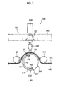
- Fig. 2 is a perspective view showing the ultrasonic bonding device 100 according to this embodiment.
- Fig. 3 is a side view (view along an arrow A of Fig. 2 ) showing the ultrasonic bonding device 100 according to this embodiment.
- the ultrasonic bonding device 100 bonds the first web 10A and the second web 20A by outputting ultrasonic vibration to a predetermined region 60.
- the ultrasonic bonding device 100 includes an anvil roll 200, an ultrasonic mechanism 300, and guide rolls 400.
- the anvil roll 200 conveys the first web 10A and the second web 20A in the conveyance direction MD while supporting the first web 10A and the second web 20A.
- the anvil roll 200 is formed in a cylindrical shape, and is provided with a body part 210 which rotates in the conveyance direction MD centering on a center shaft (not shown), and projecting parts 220 (anvil parts) which are provided in an outer circumference of the anvil roll 200 and project outward in a diameter direction of the anvil roll 200 from the body part 210.
- the projecting parts 220 come into contact with an ultrasonic horn 330 which constitutes the ultrasonic mechanism 300 to be described later with the first web 10A and the second web 20A interposed therebetween. In other words, the projecting parts 220 work with the ultrasonic mechanism 300 to pinch the first web 10A and the second web 20A.
- the multiple projecting parts 220 are provided independently.
- the independent projecting parts 220 are arranged so as to be aligned in the conveyance direction MD in the body part 210.
- the projecting part 220 includes two first projecting parts 221, 221' respectively provided in positions shifted by half of the diameter of the anvil roll 200 and two second projecting parts 222, 222' which are adjacent to the rear side in a rotational direction of the first projecting parts 221, 221', respectively.
- the first projecting parts 221, 221' and the second projecting parts 222, 222' are arranged to fit into the predetermined regions 60 of the first web 10A and the second web 20A, the predetermined regions 60 arranged with a predetermined interval (D1) in the conveyance direction MD.
- the predetermined region 60 corresponds to the bonded part 50 of the absorbent article 1.
- the predetermined region 60 is formed of a first predetermined region 61, and a second predetermined region 62 which is adjacent to the first predetermined region 61 at an interval (D2) smaller than the predetermined interval (D1) in the conveyance direction MD.
- a rotation distance (R1) between the first projecting parts 221, 221' and a rotation distance (R2) between the second projecting parts 222, 222' correspond to a distance between the first predetermined regions 61 (i.e., the above-described predetermined interval (D1)).
- a rotation distance (R3) from the first projecting part 221 to the second projecting part 222 and a rotation distance (R3') from the first projecting part 221' to the second projecting part 222' correspond to a distance from the first predetermined region 61 to the second predetermined region 62 (i.e., the above-described interval (D2)).
- the projecting parts 220 include a total of four projecting parts of the two first projecting parts 221, 221' and the two second projecting parts 222, 222', the number of the projecting parts 220 is not necessary to be four and the arrangement interval and the number thereof are selected suitably in accordance with the diameter of the anvil roll 200.
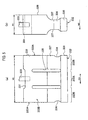
- Fig. 4 is a perspective view showing the ultrasonic mechanism 300 according to this embodiment.
- Fig. 5(a) is a front view (view along an arrow B of Fig. 4 ) showing the ultrasonic mechanism 300 according to this embodiment.
- Fig. 5(b) is a side view (view along an arrow C of Fig. 4 ) showing the ultrasonic mechanism 300 according to this embodiment.
- the ultrasonic mechanism 300 works with the first projecting parts 221, 221' and the second projecting parts 222, 222' to pinch the first web 10A and the second web 20A, so that the ultrasonic vibration is applied to the predetermined region 60 of the first web 10A and the second web 20A.
- the ultrasonic mechanism 300 is provided with an ultrasonic vibrator 310 (oscillator), a booster 320, and the ultrasonic horn 330 (vibrator).
- the ultrasonic vibrator 310 emits ultrasonic vibration to the ultrasonic horn 330 via the booster 320.
- the ultrasonic vibrator 310 is connected to the booster 320.
- the booster 320 amplifies the ultrasonic vibration outputted from the ultrasonic vibrator 310.
- the booster 320 is fixed to a pressing arm 340 which adjusts a height of the ultrasonic horn 330.
- the booster 320 transmits the amplified ultrasonic vibration to the ultrasonic horn 330.
- the ultrasonic horn 330 presses the predetermined region 60 corresponding to the bonded part 50 of the absorbent article 1 toward a side of the anvil roll 200, and applies the ultrasonic vibration to the predetermined region 60.
- the ultrasonic horn 330 works with the first projecting parts 221, 221' and the second projecting parts 222, 222' to pinch the predetermined region 60.
- the ultrasonic horn 330 is connected to the pressing arm 340 via the booster 320.
- the ultrasonic horn 330 has a width (W2) in the cross direction CD larger than a width (W1) in the conveyance direction MD.
- the ultrasonic horn 330 includes an input surface 331 to which the ultrasonic vibration generated by the ultrasonic vibrator 310 is inputted, an output surface 332 (output part) which outputs the ultrasonic vibration inputted to the input surface 331 to the predetermined region 60, and a side surface 333 provided between the input surface 331 and the output surface 332.
- the booster 320 is connected to an input center region including the center of the input surface 331.
- the input center region of the input surface 331 is dented more than regions at the outside of the input center region in the cross direction CD.
- the output surface 332 includes a central output portion 332A which outputs the ultrasonic vibration to a center region 60C of three equal regions into which the predetermined region 60 is divided with respect to the cross direction CD, and both-ends output portions 332B which output the ultrasonic vibration to both-ends regions 60S, located at both sides in the cross direction CD of the center region 60C, of the three equal regions into which the predetermined region 60 is divided.
- the side surface 333 is a surface along the conveyance direction MD, and includes a pair of first side surfaces 333A facing each other, and a pair of second side surfaces 333B having surfaces along the cross direction CD whose widths are wider than those of the first side surfaces 333A, and facing each other.
- a notch portion 334 is formed which is concaved in an arc shape from one first side surface 333A toward the other first side surface 333A.
- through-hole portions 335 are formed which penetrate from one second side surface 333B toward the other second side surface 333B.
- the ultrasonic horn 330 includes a large width portion 336 having a large width between the second side surfaces 333B (i.e., a distance in the conveyance direction MD), a small width portion 337 having a distance between the second side surfaces 333B smaller than that of the large width portion 336, and a middle width portion 338 having a distance between the second side surfaces 333B smaller than that of the large width portion 336 and a width in the conveyance direction MD larger than that of the small width portion 337, in the view seen from a side ( Fig. 5(b) ) of the ultrasonic horn 330.
- the large width portion 336 is located on a side closer to the input surface 331 than the center in a height direction of the ultrasonic horn 330.
- the small width portion 337 is located on a side closer to the output surface 332 than the large width portion 336.
- the large width portion 336 continues into the small width portion 337 in an arc shape.
- the middle width portion 338 is located closer to the side of the output surface 332 than the small width portion 337.
- the small width portion 337 continues into the middle width portion 338 in an arc shape.
- the guide rolls 400 support the first web 10A and the second web 20A.
- the guide roll 400 includes a first guide roll 410, and a second guide roll 420 which is provided at a rear side in the conveyance direction MD than the first guide roll 410.
- the first guide roll 410 leads the first web 10A and the second web 20A between the anvil roll 200 and the ultrasonic horn 330.
- the second guide roll 420 guides the first web 10A and the second web 20A to a next step after the first web 10A and the second web 20A have passed through between the anvil roll 200 and the ultrasonic horn 330 to undergo output of the ultrasonic vibration on the predetermined region 60.
- Fig. 6 is a graph showing an image of a maximum amplitude according to this embodiment.
- the anvil roll 200 i.e., the projecting part 220
- the projecting part 220 and the ultrasonic horn 330 work with each other to pinch the first web 10A and the second web 20A.
- the ultrasonic vibration generated by the ultrasonic vibrator 310 is outputted to the predetermined region 60 of the first web 10A and the second web 20A from the ultrasonic horn 330.
- a central maximum amplitude of the ultrasonic vibration outputted from the central output portion 332A to the center region 60C is smaller than an end maximum amplitude of the ultrasonic vibration outputted from each of the both-ends output portions 332B to a corresponding one of the both-ends regions 60S due to the above-described shape of the ultrasonic horn 330.
- a central bonding strength of the center region 60C bonded by the central output portion 332A is smaller than an end bonding strength of each of the both-ends regions 60S bonded by a corresponding one of the both-ends output portions 332B.
- ultrasonic vibration is converted from electrical energy by the ultrasonic vibrator 310.
- the ultrasonic vibration thus converted turns into longitudinal vibration in the diameter direction of the anvil roll 200 by the ultrasonic horn 330, after the amplitude thereof is amplified via the booster 320.
- the output surface 332 at the side of the anvil roll 200 of the ultrasonic horn 330 works with the projecting parts 220 to pinch the first web 10A and the second web 20A, so that the ultrasonic vibration is applied to the predetermined region 60.
- Fig. 7 is a schematic view showing the manufacturing method of the absorbent article 1 according to this embodiment.
- the manufacturing method of the absorbent article 1 includes at least a member placing step, a leg opening forming step, a folding step, a bonding step, and a cutting step.
- a continuous body including the first web 10A which constitutes the front waistband part 10 and the second web 20A which constitutes the rear waistband part 20 is conveyed by a conveying machine not shown (for example, a belt conveyor device) between each step.
- various members are placed on the continuous body including the first web 10A and the second web 20A (for example, a continuous body of an outer sheet) by a member mounting device 500.
- the various members include gathers (the waist gather 2 and the leg gather 3), a tarpaulin, an absorber, a top sheet (not shown), for example.
- a cut roll 600 forms the leg openings 40 (i.e., leg holes) in the continuous body on which the various members are placed after the member placing step.
- a folding device 700 folds into two the continuous body in which the leg openings 40 are formed after the leg opening forming step.
- the first web 10A and the second web 20A are overlapped with each other at the folding step.
- the ultrasonic vibration generated by the ultrasonic vibrator 310 which constitutes the above-described ultrasonic bonding device 100 is outputted to the predetermined region 60 of the first web 10A and the second web 20A from the output surface 332 of the ultrasonic horn 330, so that the predetermined region 60 is bonded.
- first web 10A and the second web 20A are conveyed in an overlapped state between the anvil roll 200 and the ultrasonic horn 330 by the above-described conveying machine.
- a cutting device 800 cuts a portion between the first predetermined region 61 and the second predetermined region 62 in the cross direction CD, so that the absorbent article 1 is formed.
- the central maximum amplitude of the ultrasonic vibration is smaller than the end maximum amplitude thereof.
- the central bonding strength is smaller than the end bonding strength. Therefore, when a wearer puts on and off the absorbent article 1 (at the time of putting on and off), the waist portion 50W and the leg portion 50L become difficult to be separated, thereby improving durability of the absorbent article 1. Further, since the waist portion 50W is not separated easily, when the wearer puts on the absorbent article 1 (at the time of putting on), the absorbent article 1 easily fits the waist portion of the wearer. Meanwhile, since the leg portion 50L is not separated easily, the leg portion 50L does not be loosened, thereby preventing excrement from the wearer from leaking from the leg portion 50L (a so-called leakage prevention capability is deteriorated).
- the bonding strength of the whole predetermined region 60 does not become strong, when the wearer disposes of the absorbent article 1 (at the time of disposal), it becomes easy to tear the bonded part 50 (a so-called disassembling property improves).
- a portion from the waist portion 50W to the leg portion 50L can be unstuck finely without the first web 10A and the second web 20A being torn in a waistband direction, by separating the bonded part from the waist portion 50W.
- the waist portion 50W and the leg portion 50L of the absorbent article 1 can be made less likely to be separated, while keeping basic properties originally needed, such as the durability of the absorbent article 1 at the time of putting on and off and the improvement of the leakage prevention capability at the time of putting on, and additional properties, such as the disassembling property at the time of disposal.
- the ultrasonic bonding device 100 according to the above-described embodiment may be changed as follows. Note that, the same reference numerals are given to the same portion as the ultrasonic bonding device 100 according to the above-described embodiment, and different portions will be mainly described.
- the ultrasonic bonding device 100 according to the above-described embodiment includes one ultrasonic horn 330.
- an ultrasonic bonding device 101 according to a modification includes multiple ultrasonic horns 330.
- the ultrasonic horn 330 which constitutes the ultrasonic bonding device 101 according to the modification does not have special shape but has a general shape, as in the above-described embodiment.
- an output surface 332 in the ultrasonic horn 330 includes therein a center portion 332C located at the center of three portions into which the output surface 332 is equally divided, and both-ends portions 332D located at both sides of the center portion 332C in the cross direction CD.
- the ultrasonic horn 330 is connected to an ultrasonic vibrator 310 in an input center region including the center of an input surface 331 corresponding to an output center region which includes the center of the output surface 332. Therefore, a maximum amplitude of the ultrasonic vibration outputted from the center portion 332C is larger than the maximum amplitude of the ultrasonic vibration outputted from the both-ends portions 332D.
- Fig. 9 is a view showing the ultrasonic bonding device 101A according to the first modification.
- the ultrasonic bonding device 101A is provided with two ultrasonic horns 330.
- the two ultrasonic horns 330 are independently provided.
- Ultrasonic vibrators 310 (not shown in Fig. 9 , see Fig. 3 ) described in the embodiment are respectively provided to the two independent ultrasonic horns 330.
- the two ultrasonic horns 330 are arranged so as to be aligned in the cross direction CD.
- An attaching position of each of the two ultrasonic horns 330 can be adjusted individually. In other words, it is possible to adjust clearances, variations, a relative position or the like of the two ultrasonic horns 330 with projecting parts 220 of an anvil roll 200.
- the two ultrasonic horns 330 are movable in the cross direction CD, the conveyance direction MD, the diameter direction of the anvil roll 200, and the like.
- Two output surfaces 332 which constitute the two ultrasonic horns 330 aligned in the cross direction CD are provided with a central output portion 332A, and both-ends output portions 332B.
- the central output portion 332A and the both-ends output portions 332B are formed of the output surfaces 332 which constitute the two ultrasonic horns 330 aligned in the cross direction CD.
- the central output portion 332A is formed of one end portion 332D of one ultrasonic horn 330 and one end portion 332D of the other ultrasonic horn 330.
- the both-ends output portions 332B are formed of portions other than the end portions 332D which constitute the central output portion 332A.
- the central maximum amplitude of the ultrasonic vibration outputted from the central output portion 332A to a center region 60C is smaller than the end maximum amplitude of the ultrasonic vibration outputted from each of the both-ends output portions 332B to a corresponding one of both-ends regions 60S.
- the central bonding strength of the center region 60C bonded by the central output portion 332A becomes smaller than the end bonding strength of each of the both-ends regions bonded by a corresponding one of the both-ends output portions 332B.
- the waist portion 50W and the leg portion 50L of the absorbent article 1 can be made difficult to be separated, while keeping the basic properties and the additional properties, as is the case with the operation and effect of the above-described embodiment. Further, since the ultrasonic horn 330 according to the first modification does not need to be a special shape, a general-purpose article can be used for the ultrasonic horn 330.
- the ultrasonic bonding device 101A since an attaching position of each of the two ultrasonic horns 330 can be adjusted individually, it is possible to adjust the output of the ultrasonic vibration from the central output portion 332A and the output of the ultrasonic vibration from the both-ends output portions 332B.
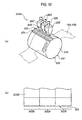
- Fig. 10 is a view showing the ultrasonic bonding device 101 B according to the second modification.
- the ultrasonic bonding device 101 B is provided with three ultrasonic horns 330.
- the three ultrasonic horns 330 are independently provided.
- Ultrasonic vibrators 310 (not shown in Fig. 10 , see Fig. 3 ) described in the embodiment are respectively provided to the three independent ultrasonic horns 330.
- the three ultrasonic horns 330 are arranged so as to be aligned in the cross direction CD.
- An attaching position of each of the three ultrasonic horns 330 can be adjusted individually. In other words, it is possible to adjust clearances, variations, a relative position or the like of the three ultrasonic horns 330 with projecting parts 220 of an anvil roll 200.
- three ultrasonic horns 330 are movable in the cross direction CD, the conveyance direction MD, the diameter direction of the anvil roll 200, and the like.
- the ultrasonic vibration generated by the ultrasonic vibrator 310 located at the center of the three ultrasonic vibrators 310 provided on the three ultrasonic horns 330 is smaller than the ultrasonic vibration generated by other ultrasonic vibrators 310 (see the dashed-dotted line of Fig. 6 ).
- Three output surfaces 332 which constitute the three ultrasonic horns 330 aligned in the cross direction CD are provided with a central output portion 332A, and both-ends output portions 332B.
- the central output portion 332A and the both-ends output portions 332B are formed of the output surfaces 332 which constitute the three ultrasonic horns 330 aligned in the cross direction CD.
- the central output portion 332A is formed of the output surface 332 of the ultrasonic horn 330' located at the center of the three ultrasonic horns 330.
- the both-ends output portions 332B are formed of the output surfaces 332 in the two ultrasonic horns 330" located at both sides of the ultrasonic horn 330' in the cross direction CD.
- the central maximum amplitude of the ultrasonic vibration outputted from the central output portion 332A to a center region 60C can be made smaller than the end maximum amplitude of the ultrasonic vibration outputted from each of the both-ends output portions 332B to a corresponding one of the both-ends regions. For this reason, the central bonding strength of the center region 60C bonded by the central output portion 332A becomes smaller than the end bonding strength of each of the both-ends regions bonded by a corresponding one of the both-ends output portions 332B.
- the ultrasonic horn 330' may shift in the conveyance direction MD (i.e., a rotational direction of the anvil roll 200) than the other two ultrasonic horns 330.
- the waist portion 50W and the leg portion 50L of the absorbent article 1 can be made difficult to be separated, while keeping the basic properties and the additional properties, as is the case with the operation and effect of the above-described embodiment.
- the ultrasonic horn 330 according to the second modification does not need to be a special shape as is the case with the first modification, a general-purpose article can be used for the ultrasonic horn 330.
- the ultrasonic bonding device 101 B since an attaching position of each of the three ultrasonic horns 330 can be adjusted individually, it is possible to adjust the output of the ultrasonic vibration from the central output portion 332A and the output of the ultrasonic vibration from the both-ends output portions 332B.
- an interval between the three ultrasonic horns 330 aligned in the cross direction CD, and the projecting parts 220 of the anvil roll 200 i.e., a clearance in the central output portion 332A
- changing a relative position of the three ultrasonic horns 330 makes it possible to adjust a relation between the central maximum amplitude and the end maximum amplitude.
- the embodiments of the present invention can be changed as follows.
- the ultrasonic bonding device is described as an example, and is not necessarily limited to the device described in the embodiments. It is needless to say that a device may be used which can apply ultrasonic vibration to the predetermined region 60 of the first web 10A and the second web 20A in a region corresponding to the bonded part 50 of the absorbent article 1.
- the manufacturing method of the absorbent article according to the present invention are advantageous since they make it possible to provide a manufacturing method of an absorbent article capable of making a waist portion and a leg portion of the absorbent article less likely to be separated while keeping the basic properties, such as the durability and the leakage prevention capability of the absorbent article, and the additional properties, such as the disassembling property thereof, when a predetermined region corresponding to a bonded part of the absorbent article is bonded by using an ultrasonic bonding device, and therefore, are useful in the manufacturing method of the disposable diaper.
Landscapes
- Engineering & Computer Science (AREA)
- Mechanical Engineering (AREA)
- Health & Medical Sciences (AREA)
- Heart & Thoracic Surgery (AREA)
- Epidemiology (AREA)
- Biomedical Technology (AREA)
- Vascular Medicine (AREA)
- Life Sciences & Earth Sciences (AREA)
- Animal Behavior & Ethology (AREA)
- General Health & Medical Sciences (AREA)
- Public Health (AREA)
- Veterinary Medicine (AREA)
- Manufacturing & Machinery (AREA)
- Absorbent Articles And Supports Therefor (AREA)
- Lining Or Joining Of Plastics Or The Like (AREA)
Abstract
Description
- The present invention relates to a manufacturing method of an absorbent article including a first web which constitutes a front waistband part, and a second web which constitutes a rear waistband part.
- Generally, an absorbent article, such as a disposable diaper, includes: a front waistband part which corresponds to a front portion around the waistline of a wearer; a rear waistband part which corresponds to a rear portion around the waistline of the wearer; a crotch part which corresponds to the crotch of the wearer; and leg openings which open at sides of the crotch part.
- The front waistband part and the rear waistband part are bonded to each other from an upper edge portion of the absorbent article from which a waistline portion of the wearer is to be inserted (i.e., an edge portion corresponding to a waist portion of the wearer) to each leg opening. These portions where the front and rear waistband parts are bonded to each other (hereinafter, referred to as bonded part) are each formed of a waist portion including a waist gather, a leg portion including a leg gather, and a fit portion located between the waist gather and the leg gather.
- A manufacturing method of such an absorbent article includes a step of bonding predetermined regions of the first web which constitutes the front waistband part and the second web which constitutes the rear waistband part which are in a overlapped state, the predetermined regions provided to the first web and the second web with a predetermined interval in a conveyance direction of the first web and the second web, and each corresponding to a bonded part.
- For example, there is known a technique of bonding a first web and a second web by outputting ultrasonic vibration to a predetermined region using an ultrasonic bonding device (for example, see Patent literature 1). The ultrasonic bonding device includes an anvil roll which supports the first web and the second web, and an ultrasonic mechanism which faces the anvil roll and which outputs the ultrasonic vibration to the predetermined region between itself and the anvil roll.
- Specifically, the ultrasonic mechanism includes an ultrasonic vibrator (oscillator) which generates ultrasonic vibration, and an ultrasonic horn (vibrator) which outputs the ultrasonic vibration generated by the ultrasonic vibrator to the predetermined region. The ultrasonic horn includes an input surface for receiving the ultrasonic vibration generated by the ultrasonic vibrator, and an output surface for outputting the ultrasonic vibration inputted to the input surface to the predetermined region. Note that, in order to output the ultrasonic vibration to the predetermined region as equally as possible, the ultrasonic vibrator and the vibrator are connected in an input center region corresponding to an output center region, the input center region including the center of the input surface, the output center region including the center of the output surface.
-
- Patent literature 1: Japanese Patent Application Publication No.
Hei 5-15551 pages Fig. 4 ) - However, the aforementioned conventional technique has the following problems. Specifically, since the ultrasonic vibrator is connected to the ultrasonic horn in the input center region, the ultrasonic vibration having inputted to the input surface from the ultrasonic vibrator is outputted in a manner of decreasing from the output center region corresponding to the input center region with distance from the output center region. In other words, the output of the ultrasonic vibration decreases with distance from the output center region.
- This makes the bonding strength of the first web and the second web in a region corresponding to each fit portion stronger than the bonding strength of the first web and the second web in a region corresponding to each waist portion, as well as than the bonding strength of the first web and the second web in a region corresponding to each leg portion.
- Therefore, when a wearer puts on and off an absorbent article (at the time of putting on and off), the waist portion and the leg portions can be separated easily, which consequently reduces the durability of the absorbent article. Further, if the waist portion can be separated easily, the absorbent article is less likely to fit the waist portion of the wearer while the wearer wears the absorbent article (while being worn). Meanwhile, if the leg portions can be separated easily, the absorbent article is less likely to fit around the legs of the wearer while being worn. Accordingly, excrement from the wearer may leak from the absorbent article (a so-called leakage prevention capability may be deteriorated).
- Conceivable methods for addressing the above problems include strongly bonding the whole predetermined region (that is, increasing the entire bonding strength). However, if the bonding strength of the whole predetermined region is increased, it becomes difficult to tear the bonded part (a so-called disassembling property is deteriorated) when the wearer disposes the absorbent article (at the time of disposal).
- As described above, in addition to basic properties originally needed, such as the improvement of the durability of the absorbent article at the time of putting on and off and the leakage prevention capability while being worn, it is required for the absorbent article to have additional properties contradictory to the basic properties, such as the disassembling property required when the wearer disposes the absorbent article (at the time of disposal).
- Thus, an object of the present invention is to provide a manufacturing method of an absorbent article capable of making a waist portion and a leg portion of the absorbent article less likely to be separated while keeping the basic properties, such as the durability and the leakage prevention capability of the absorbent article, and the additional properties, such as the disassembling property thereof, when a predetermined region corresponding to a bonded part of the absorbent article is bonded by using an ultrasonic bonding device.
- In order to solve the problem described above, the present invention has the following feature. A first feature of the present invention is a manufacturing method of an absorbent article including a first web (
first web 10A) which constitutes a front waistband part (front waistband part 10), and a second web (second web 20A) which constitutes a rear waistband part (rear waistband part 20). The method includes: a step A of conveying the first web and the second web in an overlapped state between an anvil part (projecting part 220) and a vibrator (ultrasonic horn 330) which are provided to an ultrasonic bonding device (for example, ultrasonic bonding device 100); and a step B of bonding predetermined regions (predetermined region 60) provided to the first web and the second web with a predetermined interval in a conveyance direction of the first web and the second web by outputting the ultrasonic vibration from an output part (output surface 332) of the vibrator to the predetermined regions, the ultrasonic vibration generated by an oscillator (ultrasonic vibrator 310) provided to the ultrasonic bonding device. In the method, the output part includes: a central output portion (central output portion 332A) configured to output the ultrasonic vibration to a center region (center region 60C) of three equal regions into which each predetermined region is divided in a cross direction crossing the conveyance direction; and both-ends output portions (both-ends output portions 332B) configured to output the ultrasonic vibration respectively to both-ends regions (both-ends regions 60S) of the three equal regions into which each predetermined region is divided, the both-ends regions located at both sides in the cross direction of the center region, a central maximum amplitude of the ultrasonic vibration outputted from the central output portion to the center region is smaller than an end maximum amplitude of the ultrasonic vibration outputted from each of the both-ends output portions to a corresponding one of the both-ends regions, and a central bonding strength of the center region bonded by the central output portion is smaller than an end bonding strength of each of the both-ends regions bonded by a corresponding one of the both-ends output portions. - According to the present invention, it is possible to provide a manufacturing method of an absorbent article capable of making a waist portion and a leg portion of the absorbent article less likely to be separated while keeping basic properties, such as the durability and the leakage prevention capability of the absorbent article, and additional properties, such as the disassembling property thereof, when a predetermined region corresponding to a bonded part of the absorbent article is bonded by using an ultrasonic bonding device.
-
-
Fig. 1 is a view showing anabsorbent article 1 according to this embodiment. -
Fig. 2 is a perspective view showing anultrasonic bonding device 100 according to this embodiment. -
Fig. 3 is a side view (view along an arrow A ofFig. 2 ) showing theultrasonic bonding device 100 according to this embodiment. -
Fig. 4 is a perspective view showing anultrasonic mechanism 300 according to this embodiment. -
Fig. 5 is a plan view showing theultrasonic mechanism 300 according to this embodiment. -
Fig. 6 is a graph showing an image of a maximum amplitude according to this embodiment. -
Fig. 7 is a schematic view showing a manufacturing method of theabsorbent article 1 according to this embodiment. -
Fig. 8 is a view showing anultrasonic bonding device 101 according to a modification. -
Fig. 9 is a view showing anultrasonic bonding device 101A according to a first modification. -
Fig. 10 is a view showing anultrasonic bonding device 101 B according to a second modification (No. 1). -
Fig. 11 is a view showing theultrasonic bonding device 101 B according to the second modification (No. 2). - Hereinafter, a manufacturing method of an absorbent article according to the present invention will be described with reference to the drawings. Specifically, (1) structure of absorbent article, (2) configuration of ultrasonic bonding device, (3) working of ultrasonic bonding device, (4) manufacturing method of absorbent article, (5) modifications, and (6) other embodiments will be described.
- Note that, in the description of the following drawings, the same or similar reference numerals are given to the same or similar parts. However, it should be noted that the drawings are schematic and proportions of respective dimensions and the like differ from actual ones.
- Therefore, a concrete size and the like should be determined in consideration of the following description. Further, it is needless to say that the drawings contain parts where relations and proportions of the dimensions are different from one another.
- First, a structure of an
absorbent article 1 according to this embodiment will be described with reference to the drawings.Fig. 1 (a) is a perspective view showing theabsorbent article 1 according to this embodiment.Fig. 1(b) is a plan view (front view) showing theabsorbent article 1 according to this embodiment. - As shown in
Fig. 1 , theabsorbent article 1 is provided with afront waistband part 10 corresponding to a front portion around the hip of a wearer, arear waistband part 20 corresponding to a rear portion around the hip of the wearer, acrotch part 30 corresponding to the crotch of the wearer,leg openings 40 which open in side portions of thecrotch part 30. - The
front waistband part 10 and therear waistband part 20 are bonded to each other from an upper edge portion of theabsorbent article 1 into which a hip portion of the wearer is to be inserted (i.e., an edge portion corresponding to a waist portion of the wearer), to theleg openings 40. This portion bonded to each other (hereinafter, bonded part 50) is formed of awaist portion 50W including awaist gather 2, aleg portion 50L including a leg gather 3, and afit portion 50F located between the waist gather 2 and the leg gather 3. - The
front waistband part 10 and therear waistband part 20 is stretchy in a conveyance direction MD of afirst web 10A which constitutes the front waistband part 10 (seeFig. 2 or3 ), and asecond web 20A which constitutes the rear waistband part 20 (seeFig. 2 or3 ). For example, thefront waistband part 10 and therear waistband part 20 may be stretchy in the conveyance direction MD by being provided with the above-described waist gather 2, and may be stretchy in the conveyance direction MD by forming thefirst web 10A and thesecond web 20A themselves with a stretchy sheet. - The
crotch part 30 is stretchy in a cross direction CD crossing the conveyance direction MD. For example, thecrotch part 30 may be stretchy in the cross direction CD by being provided with the above-described leg gather 3, and may be stretchy in the cross direction CD by forming thefirst web 10A and thesecond web 20A themselves with a stretchy sheet. - Next, a configuration of an
ultrasonic bonding device 100 according to this embodiment will be described with reference to the drawings.Fig. 2 is a perspective view showing theultrasonic bonding device 100 according to this embodiment.Fig. 3 is a side view (view along an arrow A ofFig. 2 ) showing theultrasonic bonding device 100 according to this embodiment. - As shown in
Figs. 2 and3 , theultrasonic bonding device 100 bonds thefirst web 10A and thesecond web 20A by outputting ultrasonic vibration to apredetermined region 60. Theultrasonic bonding device 100 includes ananvil roll 200, anultrasonic mechanism 300, and guide rolls 400. - First, a configuration of the
anvil roll 200 will be described with reference toFigs. 2 and3 . As shown inFigs. 2 and3 , theanvil roll 200 conveys thefirst web 10A and thesecond web 20A in the conveyance direction MD while supporting thefirst web 10A and thesecond web 20A. - The
anvil roll 200 is formed in a cylindrical shape, and is provided with abody part 210 which rotates in the conveyance direction MD centering on a center shaft (not shown), and projecting parts 220 (anvil parts) which are provided in an outer circumference of theanvil roll 200 and project outward in a diameter direction of theanvil roll 200 from thebody part 210. - The projecting
parts 220 come into contact with anultrasonic horn 330 which constitutes theultrasonic mechanism 300 to be described later with thefirst web 10A and thesecond web 20A interposed therebetween. In other words, the projectingparts 220 work with theultrasonic mechanism 300 to pinch thefirst web 10A and thesecond web 20A. - The multiple projecting
parts 220 are provided independently. The independent projectingparts 220 are arranged so as to be aligned in the conveyance direction MD in thebody part 210. Specifically, the projectingpart 220 includes two first projectingparts 221, 221' respectively provided in positions shifted by half of the diameter of theanvil roll 200 and two second projectingparts 222, 222' which are adjacent to the rear side in a rotational direction of the first projectingparts 221, 221', respectively. - The first projecting
parts 221, 221' and the second projectingparts 222, 222' are arranged to fit into thepredetermined regions 60 of thefirst web 10A and thesecond web 20A, thepredetermined regions 60 arranged with a predetermined interval (D1) in the conveyance direction MD. - Here, the
predetermined region 60 corresponds to the bondedpart 50 of theabsorbent article 1. Specifically, thepredetermined region 60 is formed of a firstpredetermined region 61, and a secondpredetermined region 62 which is adjacent to the firstpredetermined region 61 at an interval (D2) smaller than the predetermined interval (D1) in the conveyance direction MD. - In other words, as shown in
Fig. 3 , a rotation distance (R1) between the first projectingparts 221, 221' and a rotation distance (R2) between the second projectingparts 222, 222' correspond to a distance between the first predetermined regions 61 (i.e., the above-described predetermined interval (D1)). Further, a rotation distance (R3) from the first projectingpart 221 to the second projectingpart 222 and a rotation distance (R3') from the first projecting part 221' to the second projecting part 222' correspond to a distance from the firstpredetermined region 61 to the second predetermined region 62 (i.e., the above-described interval (D2)). - Here, although the projecting
parts 220 include a total of four projecting parts of the two first projectingparts 221, 221' and the two second projectingparts 222, 222', the number of the projectingparts 220 is not necessary to be four and the arrangement interval and the number thereof are selected suitably in accordance with the diameter of theanvil roll 200. - Next, a configuration of the
ultrasonic mechanism 300 will be described with reference toFigs. 2 to 5 .Fig. 4 is a perspective view showing theultrasonic mechanism 300 according to this embodiment.Fig. 5(a) is a front view (view along an arrow B ofFig. 4 ) showing theultrasonic mechanism 300 according to this embodiment.Fig. 5(b) is a side view (view along an arrow C ofFig. 4 ) showing theultrasonic mechanism 300 according to this embodiment. - As shown in
Figs. 2 and3 , theultrasonic mechanism 300 works with the first projectingparts 221, 221' and the second projectingparts 222, 222' to pinch thefirst web 10A and thesecond web 20A, so that the ultrasonic vibration is applied to thepredetermined region 60 of thefirst web 10A and thesecond web 20A. Theultrasonic mechanism 300 is provided with an ultrasonic vibrator 310 (oscillator), abooster 320, and the ultrasonic horn 330 (vibrator). - As shown in
Fig. 3 , theultrasonic vibrator 310 emits ultrasonic vibration to theultrasonic horn 330 via thebooster 320. Theultrasonic vibrator 310 is connected to thebooster 320. - As shown in
Fig. 3 , thebooster 320 amplifies the ultrasonic vibration outputted from theultrasonic vibrator 310. Thebooster 320 is fixed to apressing arm 340 which adjusts a height of theultrasonic horn 330. Thebooster 320 transmits the amplified ultrasonic vibration to theultrasonic horn 330. - As shown in
Fig. 3 , theultrasonic horn 330 presses thepredetermined region 60 corresponding to the bondedpart 50 of theabsorbent article 1 toward a side of theanvil roll 200, and applies the ultrasonic vibration to thepredetermined region 60. In other words, theultrasonic horn 330 works with the first projectingparts 221, 221' and the second projectingparts 222, 222' to pinch thepredetermined region 60. Theultrasonic horn 330 is connected to thepressing arm 340 via thebooster 320. - As shown in
Figs. 4 and5 , theultrasonic horn 330 has a width (W2) in the cross direction CD larger than a width (W1) in the conveyance direction MD. Theultrasonic horn 330 includes aninput surface 331 to which the ultrasonic vibration generated by theultrasonic vibrator 310 is inputted, an output surface 332 (output part) which outputs the ultrasonic vibration inputted to theinput surface 331 to thepredetermined region 60, and aside surface 333 provided between theinput surface 331 and theoutput surface 332. - The
booster 320 is connected to an input center region including the center of theinput surface 331. The input center region of theinput surface 331 is dented more than regions at the outside of the input center region in the cross direction CD. - The
output surface 332 includes acentral output portion 332A which outputs the ultrasonic vibration to acenter region 60C of three equal regions into which thepredetermined region 60 is divided with respect to the cross direction CD, and both-endsoutput portions 332B which output the ultrasonic vibration to both-ends regions 60S, located at both sides in the cross direction CD of thecenter region 60C, of the three equal regions into which thepredetermined region 60 is divided. - The
side surface 333 is a surface along the conveyance direction MD, and includes a pair of first side surfaces 333A facing each other, and a pair of second side surfaces 333B having surfaces along the cross direction CD whose widths are wider than those of the first side surfaces 333A, and facing each other. - In each
first side surface 333A, anotch portion 334 is formed which is concaved in an arc shape from onefirst side surface 333A toward the otherfirst side surface 333A. In the second side surfaces 333B, through-hole portions 335 are formed which penetrate from onesecond side surface 333B toward the othersecond side surface 333B. - The
ultrasonic horn 330 includes alarge width portion 336 having a large width between the second side surfaces 333B (i.e., a distance in the conveyance direction MD), asmall width portion 337 having a distance between the second side surfaces 333B smaller than that of thelarge width portion 336, and amiddle width portion 338 having a distance between the second side surfaces 333B smaller than that of thelarge width portion 336 and a width in the conveyance direction MD larger than that of thesmall width portion 337, in the view seen from a side (Fig. 5(b) ) of theultrasonic horn 330. - The
large width portion 336 is located on a side closer to theinput surface 331 than the center in a height direction of theultrasonic horn 330. Thesmall width portion 337 is located on a side closer to theoutput surface 332 than thelarge width portion 336. Thelarge width portion 336 continues into thesmall width portion 337 in an arc shape. Themiddle width portion 338 is located closer to the side of theoutput surface 332 than thesmall width portion 337. Thesmall width portion 337 continues into themiddle width portion 338 in an arc shape. - The guide rolls 400 support the
first web 10A and thesecond web 20A. Specifically, theguide roll 400 includes afirst guide roll 410, and asecond guide roll 420 which is provided at a rear side in the conveyance direction MD than thefirst guide roll 410. - The
first guide roll 410 leads thefirst web 10A and thesecond web 20A between theanvil roll 200 and theultrasonic horn 330. Thesecond guide roll 420 guides thefirst web 10A and thesecond web 20A to a next step after thefirst web 10A and thesecond web 20A have passed through between theanvil roll 200 and theultrasonic horn 330 to undergo output of the ultrasonic vibration on thepredetermined region 60. - Next, a working of the
ultrasonic bonding device 100 according to this embodiment will be described with reference toFig. 6. Fig. 6 is a graph showing an image of a maximum amplitude according to this embodiment. - In the
ultrasonic bonding device 100, theanvil roll 200, i.e., the projectingpart 220, rotates in association with the conveyance of thefirst web 10A and thesecond web 20A. At this time, the projectingpart 220 and theultrasonic horn 330 work with each other to pinch thefirst web 10A and thesecond web 20A. Thereby, the ultrasonic vibration generated by theultrasonic vibrator 310 is outputted to thepredetermined region 60 of thefirst web 10A and thesecond web 20A from theultrasonic horn 330. - At this time, as shown by the solid line in
Fig. 6 , a central maximum amplitude of the ultrasonic vibration outputted from thecentral output portion 332A to thecenter region 60C is smaller than an end maximum amplitude of the ultrasonic vibration outputted from each of the both-endsoutput portions 332B to a corresponding one of the both-ends regions 60S due to the above-described shape of theultrasonic horn 330. For this reason, a central bonding strength of thecenter region 60C bonded by thecentral output portion 332A is smaller than an end bonding strength of each of the both-ends regions 60S bonded by a corresponding one of the both-endsoutput portions 332B. - Here, ultrasonic vibration is converted from electrical energy by the
ultrasonic vibrator 310. The ultrasonic vibration thus converted turns into longitudinal vibration in the diameter direction of theanvil roll 200 by theultrasonic horn 330, after the amplitude thereof is amplified via thebooster 320. Theoutput surface 332 at the side of theanvil roll 200 of theultrasonic horn 330 works with the projectingparts 220 to pinch thefirst web 10A and thesecond web 20A, so that the ultrasonic vibration is applied to thepredetermined region 60. - Next, a manufacturing method of the
absorbent article 1 according to this embodiment will be described with reference to the drawings.Fig. 7 is a schematic view showing the manufacturing method of theabsorbent article 1 according to this embodiment. - As shown in
Fig. 7 , the manufacturing method of theabsorbent article 1 includes at least a member placing step, a leg opening forming step, a folding step, a bonding step, and a cutting step. Here, a continuous body including thefirst web 10A which constitutes thefront waistband part 10 and thesecond web 20A which constitutes therear waistband part 20 is conveyed by a conveying machine not shown (for example, a belt conveyor device) between each step. - At the member placing step, various members are placed on the continuous body including the
first web 10A and thesecond web 20A (for example, a continuous body of an outer sheet) by amember mounting device 500. The various members include gathers (the waist gather 2 and the leg gather 3), a tarpaulin, an absorber, a top sheet (not shown), for example. - At the leg opening forming step, a
cut roll 600 forms the leg openings 40 (i.e., leg holes) in the continuous body on which the various members are placed after the member placing step. - At the folding step, a
folding device 700 folds into two the continuous body in which theleg openings 40 are formed after the leg opening forming step. In other words, thefirst web 10A and thesecond web 20A are overlapped with each other at the folding step. - At the bonding step, after the folding step, the ultrasonic vibration generated by the
ultrasonic vibrator 310 which constitutes the above-describedultrasonic bonding device 100 is outputted to thepredetermined region 60 of thefirst web 10A and thesecond web 20A from theoutput surface 332 of theultrasonic horn 330, so that thepredetermined region 60 is bonded. - Here, the
first web 10A and thesecond web 20A are conveyed in an overlapped state between theanvil roll 200 and theultrasonic horn 330 by the above-described conveying machine. - At the cutting step, after the bonding step, a
cutting device 800 cuts a portion between the firstpredetermined region 61 and the secondpredetermined region 62 in the cross direction CD, so that theabsorbent article 1 is formed. - According to the embodiment, the central maximum amplitude of the ultrasonic vibration is smaller than the end maximum amplitude thereof. For this reason, the central bonding strength is smaller than the end bonding strength. Therefore, when a wearer puts on and off the absorbent article 1 (at the time of putting on and off), the
waist portion 50W and theleg portion 50L become difficult to be separated, thereby improving durability of theabsorbent article 1. Further, since thewaist portion 50W is not separated easily, when the wearer puts on the absorbent article 1 (at the time of putting on), theabsorbent article 1 easily fits the waist portion of the wearer. Meanwhile, since theleg portion 50L is not separated easily, theleg portion 50L does not be loosened, thereby preventing excrement from the wearer from leaking from theleg portion 50L (a so-called leakage prevention capability is deteriorated). - Further, since the bonding strength of the whole
predetermined region 60 does not become strong, when the wearer disposes of the absorbent article 1 (at the time of disposal), it becomes easy to tear the bonded part 50 (a so-called disassembling property improves). At the time of the usual disposal, a portion from thewaist portion 50W to theleg portion 50L can be unstuck finely without thefirst web 10A and thesecond web 20A being torn in a waistband direction, by separating the bonded part from thewaist portion 50W. - As describe above, the
waist portion 50W and theleg portion 50L of theabsorbent article 1 can be made less likely to be separated, while keeping basic properties originally needed, such as the durability of theabsorbent article 1 at the time of putting on and off and the improvement of the leakage prevention capability at the time of putting on, and additional properties, such as the disassembling property at the time of disposal. - The
ultrasonic bonding device 100 according to the above-described embodiment may be changed as follows. Note that, the same reference numerals are given to the same portion as theultrasonic bonding device 100 according to the above-described embodiment, and different portions will be mainly described. - The
ultrasonic bonding device 100 according to the above-described embodiment includes oneultrasonic horn 330. On the other hand, anultrasonic bonding device 101 according to a modification includes multipleultrasonic horns 330. Theultrasonic horn 330 which constitutes theultrasonic bonding device 101 according to the modification does not have special shape but has a general shape, as in the above-described embodiment. - Specifically, as shown in
Fig. 8 , anoutput surface 332 in theultrasonic horn 330 according to the modification includes therein acenter portion 332C located at the center of three portions into which theoutput surface 332 is equally divided, and both-endsportions 332D located at both sides of thecenter portion 332C in the cross direction CD. - The
ultrasonic horn 330 according to the modification is connected to anultrasonic vibrator 310 in an input center region including the center of aninput surface 331 corresponding to an output center region which includes the center of theoutput surface 332. Therefore, a maximum amplitude of the ultrasonic vibration outputted from thecenter portion 332C is larger than the maximum amplitude of the ultrasonic vibration outputted from the both-ends portions 332D. - First, a configuration of an
ultrasonic bonding device 101A according to a first modification will be described with reference to the drawings.Fig. 9 is a view showing theultrasonic bonding device 101A according to the first modification. - As shown in
Fig. 9 , theultrasonic bonding device 101A is provided with twoultrasonic horns 330. In other words, the twoultrasonic horns 330 are independently provided. Ultrasonic vibrators 310 (not shown inFig. 9 , seeFig. 3 ) described in the embodiment are respectively provided to the two independentultrasonic horns 330. - The two
ultrasonic horns 330 are arranged so as to be aligned in the cross direction CD. An attaching position of each of the twoultrasonic horns 330 can be adjusted individually. In other words, it is possible to adjust clearances, variations, a relative position or the like of the twoultrasonic horns 330 with projectingparts 220 of ananvil roll 200. For example, the twoultrasonic horns 330 are movable in the cross direction CD, the conveyance direction MD, the diameter direction of theanvil roll 200, and the like. - Two
ultrasonic vibrators 310 provided on the twoultrasonic horns 330 generate the same ultrasonic vibration respectively. For this reason, the maximum amplitude of the ultrasonic vibration outputted from acenter portion 332C is larger than the maximum amplitude of the ultrasonic vibration outputted from both-ends portions 332D (see the dashed line ofFig. 6 ). - Two
output surfaces 332 which constitute the twoultrasonic horns 330 aligned in the cross direction CD are provided with acentral output portion 332A, and both-endsoutput portions 332B. In other words, thecentral output portion 332A and the both-endsoutput portions 332B are formed of the output surfaces 332 which constitute the twoultrasonic horns 330 aligned in the cross direction CD. - In other words, the
central output portion 332A is formed of oneend portion 332D of oneultrasonic horn 330 and oneend portion 332D of the otherultrasonic horn 330. The both-endsoutput portions 332B are formed of portions other than theend portions 332D which constitute thecentral output portion 332A. - Thus, since the two
ultrasonic horns 330 are arranged so as to be aligned in the cross direction CD, the central maximum amplitude of the ultrasonic vibration outputted from thecentral output portion 332A to acenter region 60C is smaller than the end maximum amplitude of the ultrasonic vibration outputted from each of the both-endsoutput portions 332B to a corresponding one of both-ends regions 60S. For this reason, the central bonding strength of thecenter region 60C bonded by thecentral output portion 332A becomes smaller than the end bonding strength of each of the both-ends regions bonded by a corresponding one of the both-endsoutput portions 332B. - According to the
ultrasonic bonding device 101 A according to the first modification, thewaist portion 50W and theleg portion 50L of theabsorbent article 1 can be made difficult to be separated, while keeping the basic properties and the additional properties, as is the case with the operation and effect of the above-described embodiment. Further, since theultrasonic horn 330 according to the first modification does not need to be a special shape, a general-purpose article can be used for theultrasonic horn 330. - According to the
ultrasonic bonding device 101A according to the first modification, since an attaching position of each of the twoultrasonic horns 330 can be adjusted individually, it is possible to adjust the output of the ultrasonic vibration from thecentral output portion 332A and the output of the ultrasonic vibration from the both-endsoutput portions 332B. - For example, changing an interval between the two
ultrasonic horns 330 aligned in the cross direction CD, and the projectingparts 220 of the anvil roll 200 (i.e., a clearance in thecentral output portion 332A) makes it possible to adjust a relation between a pressure of the ultrasonic vibration in thecentral output portion 332A and a pressure of the ultrasonic vibration in the both-endsoutput portions 332B. Further, changing a relative position of the twoultrasonic horns 330 makes it possible to adjust a relation between the central maximum amplitude and the end maximum amplitude. - First, a configuration of an
ultrasonic bonding device 101 B according to a second modification will be described with reference to the drawings.Fig. 10 is a view showing theultrasonic bonding device 101 B according to the second modification. - As shown in
Fig. 10 , theultrasonic bonding device 101 B is provided with threeultrasonic horns 330. In other words, the threeultrasonic horns 330 are independently provided. Ultrasonic vibrators 310 (not shown inFig. 10 , seeFig. 3 ) described in the embodiment are respectively provided to the three independentultrasonic horns 330. The threeultrasonic horns 330 are arranged so as to be aligned in the cross direction CD. An attaching position of each of the threeultrasonic horns 330 can be adjusted individually. In other words, it is possible to adjust clearances, variations, a relative position or the like of the threeultrasonic horns 330 with projectingparts 220 of ananvil roll 200. For example, threeultrasonic horns 330 are movable in the cross direction CD, the conveyance direction MD, the diameter direction of theanvil roll 200, and the like. - The ultrasonic vibration generated by the
ultrasonic vibrator 310 located at the center of the threeultrasonic vibrators 310 provided on the threeultrasonic horns 330 is smaller than the ultrasonic vibration generated by other ultrasonic vibrators 310 (see the dashed-dotted line ofFig. 6 ). - Three
output surfaces 332 which constitute the threeultrasonic horns 330 aligned in the cross direction CD are provided with acentral output portion 332A, and both-endsoutput portions 332B. In other words, thecentral output portion 332A and the both-endsoutput portions 332B are formed of the output surfaces 332 which constitute the threeultrasonic horns 330 aligned in the cross direction CD. - In other words, the
central output portion 332A is formed of theoutput surface 332 of theultrasonic horn 330' located at the center of the threeultrasonic horns 330. The both-endsoutput portions 332B are formed of the output surfaces 332 in the twoultrasonic horns 330" located at both sides of theultrasonic horn 330' in the cross direction CD. - Thus, the central maximum amplitude of the ultrasonic vibration outputted from the
central output portion 332A to acenter region 60C can be made smaller than the end maximum amplitude of the ultrasonic vibration outputted from each of the both-endsoutput portions 332B to a corresponding one of the both-ends regions. For this reason, the central bonding strength of thecenter region 60C bonded by thecentral output portion 332A becomes smaller than the end bonding strength of each of the both-ends regions bonded by a corresponding one of the both-endsoutput portions 332B. - Although the description has been made here that the three
ultrasonic horns 330 are arranged so as to be aligned in the cross direction CD in theultrasonic bonding device 101 B according to the second modification, not limited to this, as shown inFig. 11 , theultrasonic horn 330' may shift in the conveyance direction MD (i.e., a rotational direction of the anvil roll 200) than the other twoultrasonic horns 330. - According to the
ultrasonic bonding device 101 B according to the second modification, thewaist portion 50W and theleg portion 50L of theabsorbent article 1 can be made difficult to be separated, while keeping the basic properties and the additional properties, as is the case with the operation and effect of the above-described embodiment. Further, since theultrasonic horn 330 according to the second modification does not need to be a special shape as is the case with the first modification, a general-purpose article can be used for theultrasonic horn 330. - According to the
ultrasonic bonding device 101 B according to the second modification, since an attaching position of each of the threeultrasonic horns 330 can be adjusted individually, it is possible to adjust the output of the ultrasonic vibration from thecentral output portion 332A and the output of the ultrasonic vibration from the both-endsoutput portions 332B. - For example, changing an interval between the three
ultrasonic horns 330 aligned in the cross direction CD, and the projectingparts 220 of the anvil roll 200 (i.e., a clearance in thecentral output portion 332A) makes it possible to adjust a relation between a pressure of the ultrasonic vibration in thecentral output portion 332A and a pressure of the ultrasonic vibration in the both-endsoutput portions 332B. Further, changing a relative position of the threeultrasonic horns 330 makes it possible to adjust a relation between the central maximum amplitude and the end maximum amplitude. - As described above, the contents of the present invention has been disclosed through the embodiments of the present invention. However, it should not be understood that the statement and the drawings which make a part of this disclosure limit the present invention. Various alternative embodiments, examples, and operational techniques will be apparent to those skilled in the art from this disclosure.
- For example, the embodiments of the present invention can be changed as follows. Specifically, the ultrasonic bonding device is described as an example, and is not necessarily limited to the device described in the embodiments. It is needless to say that a device may be used which can apply ultrasonic vibration to the
predetermined region 60 of thefirst web 10A and thesecond web 20A in a region corresponding to the bondedpart 50 of theabsorbent article 1. - Further, there is no restriction in particular about a shape, a structure, an arrangement, and the like of the
ultrasonic horn 330, and similarly, there is no restriction in particular about a shape, a structure, an arrangement, and the like of the anvil roll 200 (the projecting part 220), and they can be chosen suitably depending on the purpose. - Thus, the present invention naturally includes various embodiments and the like which have not been described here. Therefore, the technical scope of the present invention is defined only by the invention specific matter according to the appended claims which are appropriate from the above-described description.
- Note that, the entire contents of Japanese Patent Application No.
2008-289309 (filed on November 11, 2008 - As described above, the manufacturing method of the absorbent article according to the present invention are advantageous since they make it possible to provide a manufacturing method of an absorbent article capable of making a waist portion and a leg portion of the absorbent article less likely to be separated while keeping the basic properties, such as the durability and the leakage prevention capability of the absorbent article, and the additional properties, such as the disassembling property thereof, when a predetermined region corresponding to a bonded part of the absorbent article is bonded by using an ultrasonic bonding device, and therefore, are useful in the manufacturing method of the disposable diaper.
Claims (7)
- A manufacturing method of an absorbent article including a first web which constitutes a front waistband part, and a second web which constitutes a rear waistband part, the method comprising:a step A of conveying the first web and the second web in an overlapped state between an anvil part and a vibrator which are provided to an ultrasonic bonding device; anda step B of bonding predetermined regions provided to the first web and the second web with a predetermined interval in a conveyance direction of the first web and the second web by outputting an ultrasonic vibration from an output part of the vibrator to the predetermined regions, the ultrasonic vibration generated by an oscillator provided to the ultrasonic bonding device, whereinthe output part includes:a central output portion configured to output the ultrasonic vibration to a center region of three equal regions into which each predetermined region is divided in a cross direction crossing the conveyance direction; andboth-ends output portions configured to output the ultrasonic vibration respectively to both-ends regions of the three equal regions into which each predetermined region is divided, the both-ends regions located at both sides in the cross direction of the center region,a central maximum amplitude of the ultrasonic vibration outputted from the central output portion to the center region is smaller than an end maximum amplitude of the ultrasonic vibration outputted from each of the both-ends output portions to a corresponding one of the both-ends regions, anda central bonding strength of the center region bonded by the central output portion is smaller than an end bonding strength of each of the both-ends regions bonded by a corresponding one of the both-ends output portions.
- The manufacturing method of an absorbent article according to claim 1, wherein
a plurality of the vibrators are independently provided, and
the oscillator is provided in each of the independent vibrators. - The manufacturing method of an absorbent article according to claim 2, wherein the independent vibrators are arranged so as to be aligned in the cross direction.
- The manufacturing method of an absorbent article according to any one of claims 1 to 3, wherein
a plurality of the anvil parts are independently provided, and
the independent anvil parts are arranged so as to be aligned in the conveyance direction. - The manufacturing method of an absorbent article according to any one of claims 1 to 4, wherein the central maximum amplitude is made smaller than the end maximum amplitude, and the central bonding strength is made smaller than the end bonding strength, by changing a shape of the vibrator.
- The manufacturing method of an absorbent article according to any one of claims 1 to 5, further comprising a step C of overlapping the first web and the second web before the step A.
- The manufacturing method of an absorbent article according to any one of claims 1 to 6, wherein
each predetermined region includes:a first predetermined region; anda second predetermined region which is adjacent to the first predetermined region with an interval smaller than the predetermined interval in the conveyance direction, andfurther comprising a step D of cutting a line between the first predetermined region and the second predetermined region in the cross direction after the step B in order to form the absorbent article.
Applications Claiming Priority (2)
| Application Number | Priority Date | Filing Date | Title |
|---|---|---|---|
| JP2008289309A JP5247364B2 (en) | 2008-11-11 | 2008-11-11 | Method for manufacturing absorbent article |
| PCT/JP2009/069200 WO2010055854A1 (en) | 2008-11-11 | 2009-11-11 | Method of manufacturing absorptive article |
Publications (3)
| Publication Number | Publication Date |
|---|---|
| EP2359786A1 true EP2359786A1 (en) | 2011-08-24 |
| EP2359786A4 EP2359786A4 (en) | 2013-03-06 |
| EP2359786B1 EP2359786B1 (en) | 2016-07-20 |
Family
ID=42164099
Family Applications (1)
| Application Number | Title | Priority Date | Filing Date |
|---|---|---|---|
| EP09826101.9A Active EP2359786B1 (en) | 2008-11-11 | 2009-11-11 | Method of manufacturing absorptive article |
Country Status (10)
| Country | Link |
|---|---|
| US (1) | US7887656B2 (en) |
| EP (1) | EP2359786B1 (en) |
| JP (1) | JP5247364B2 (en) |
| KR (1) | KR101513773B1 (en) |
| CN (1) | CN102209513B (en) |
| AR (1) | AR074101A1 (en) |
| AU (1) | AU2009314983B2 (en) |
| BR (1) | BRPI0915253A2 (en) |
| EA (1) | EA020073B1 (en) |
| WO (1) | WO2010055854A1 (en) |
Families Citing this family (29)
| Publication number | Priority date | Publication date | Assignee | Title |
|---|---|---|---|---|
| US8411671B1 (en) * | 2009-03-24 | 2013-04-02 | Sprint Communications Company L.P. | Loss adjustment control in a tandem media communication network |
| JP5491081B2 (en) * | 2009-06-22 | 2014-05-14 | 株式会社アルテクス | Resonator for ultrasonic vibration metal bonding |
| JP5366697B2 (en) * | 2009-07-31 | 2013-12-11 | ユニ・チャーム株式会社 | Web joining apparatus and web joining method |
| JP5475355B2 (en) * | 2009-07-31 | 2014-04-16 | ユニ・チャーム株式会社 | Ultrasonic bonding apparatus and absorbent article manufacturing apparatus |
| JP5591051B2 (en) * | 2010-09-30 | 2014-09-17 | ユニ・チャーム株式会社 | Apparatus and method for sonicating a web |
| JP5623228B2 (en) * | 2010-09-30 | 2014-11-12 | ユニ・チャーム株式会社 | Ultrasonic treatment equipment |
| ES2403011T3 (en) | 2010-10-07 | 2013-05-13 | Eurocopter Deutschland Gmbh | Apparatus and procedure for automatic, continuous preform production |
| CN202670170U (en) * | 2011-05-11 | 2013-01-16 | 株式会社石田 | Transverse-sealing device for packaging machine |
| JP5851297B2 (en) | 2012-03-22 | 2016-02-03 | ユニ・チャーム株式会社 | Apparatus and method for sonicating a web |
| JP5986855B2 (en) * | 2012-09-11 | 2016-09-06 | 王子ネピア株式会社 | Sheet joining apparatus and method for manufacturing disposable diaper using joining apparatus |
| CN105283300B (en) * | 2013-06-14 | 2017-12-12 | 株式会社瑞光 | Wave welding head of ultrasonic wave, the heat sealing machine for possessing the wave welding head of ultrasonic wave and make use of wave welding head of ultrasonic wave disposable diaper manufacture method |
| JP6201525B2 (en) * | 2013-08-26 | 2017-09-27 | 王子ホールディングス株式会社 | Sheet joining apparatus and method for manufacturing disposable diaper using joining apparatus |
| BR112016015004B1 (en) | 2013-12-26 | 2021-01-05 | Zuiko Corporation | ultrasonic welding device |
| CN107530203B (en) * | 2015-05-04 | 2021-11-12 | Gdm股份公司 | Unit for forming absorbent sanitary articles and method for manufacturing absorbent sanitary articles |
| ITUB20150807A1 (en) * | 2015-05-15 | 2016-11-15 | Fameccanica Data Spa | DEVICE AND METHOD FOR CARRYING OUT ULTRASONIC WELDINGS ON CONTINUOUS MOVING TAPE MATERIALS |
| JP6600552B2 (en) * | 2015-12-22 | 2019-10-30 | 花王株式会社 | Manufacturing method of pant-type absorbent article |
| JP6931515B2 (en) | 2016-04-18 | 2021-09-08 | エディソン ウェルディング インスティテュート、インク. | Modular ultrasound equipment used in package sealing systems |
| US20200361158A1 (en) * | 2017-09-15 | 2020-11-19 | Zuiko Corporation | Apparatus for manufacturing wearing article and method of manufacturing same |
| BR112020021683B1 (en) * | 2018-04-30 | 2023-10-17 | Kimberly-Clark Worldwide, Inc. | METHOD FOR FORMING ABSORBENT ARTICLES |
| CN108943734A (en) * | 2018-06-22 | 2018-12-07 | 安徽珂力智能电气有限公司 | Adult incontinence pants segmented hot welding equipment and thermal weld method |
| CN108943735A (en) * | 2018-06-22 | 2018-12-07 | 安徽珂力智能电气有限公司 | Adult incontinence pants multiple roll ultrasonic brazing unit and method |
| JP6683994B2 (en) * | 2018-07-30 | 2020-04-22 | 株式会社マルヤテキスタイル | Ultrasonic punching device and ultrasonic punching method |
| KR102710862B1 (en) * | 2019-03-05 | 2024-09-27 | 삼성디스플레이 주식회사 | Manufacturing device for the display device and method of manufacturing for the display device |
| CN114728475B (en) * | 2019-11-19 | 2024-10-29 | 花王株式会社 | Composite sheet manufacturing method and manufacturing device, composite sheet and absorbent article |
| DE102020200184A1 (en) * | 2020-01-09 | 2021-07-15 | Magna Exteriors (Bohemia) s.r.o. | Process for the ultrasonic welding of two plastic components and the plastic components produced in this way |
| KR102837947B1 (en) * | 2020-10-22 | 2025-07-24 | 주식회사 엘지에너지솔루션 | Ultrasonic Welding Device Comprising Rotatable Anvil and Welding Method |
| US12427725B2 (en) | 2020-12-17 | 2025-09-30 | Kimberly-Clark Worldwide, Inc. | Energy mechanism assemblies and methods of providing energy to an item |
| JP7170760B2 (en) * | 2021-01-22 | 2022-11-14 | 株式会社リブドゥコーポレーション | ULTRASONIC WELDING DEVICE AND SIDE SEAL FORMING METHOD |
| CN113737508A (en) * | 2021-08-30 | 2021-12-03 | 黄山富田精工智造股份有限公司 | A kind of method and structure of cutting spandex yarn located in non-woven interlayer |
Family Cites Families (19)
| Publication number | Priority date | Publication date | Assignee | Title |
|---|---|---|---|---|
| US3113225A (en) * | 1960-06-09 | 1963-12-03 | Cavitron Ultrasonics Inc | Ultrasonic vibration generator |
| US3733238A (en) * | 1971-12-13 | 1973-05-15 | Crompton & Knowles Corp | Apparatus for vibration welding of sheet materials |
| JPS515551A (en) * | 1974-07-04 | 1976-01-17 | Mitsubishi Electric Corp | HANDOTA ISOCHI |
| US4414045A (en) * | 1982-02-22 | 1983-11-08 | Burlington Industries, Inc. | High speed ultrasonic bonding |
| JPS62273832A (en) * | 1986-05-23 | 1987-11-27 | Eiji Mori | Tool horn for ultrasonic plastic welder |
| JPH03183527A (en) * | 1989-12-13 | 1991-08-09 | Hitachi Constr Mach Co Ltd | Ultrasonic joining equipment |
| JP2745338B2 (en) * | 1990-10-03 | 1998-04-28 | コニカ株式会社 | Web joining method |
| JP3112710B2 (en) * | 1991-07-15 | 2000-11-27 | ユニ・チャーム株式会社 | Method and apparatus for joining pants-type wearing articles |
| JP3205391B2 (en) * | 1992-06-18 | 2001-09-04 | 精電舎電子工業株式会社 | Tool horn for compound vibration |
| JP3340475B2 (en) * | 1992-09-08 | 2002-11-05 | 株式会社ネオックスラボ | Ultrasonic welding equipment |
| US5788791A (en) * | 1996-07-03 | 1998-08-04 | Branson Ultrasonics Corporation | Method of determining the collapse of plastic parts |
| JP3503496B2 (en) * | 1998-10-22 | 2004-03-08 | トヨタ自動車株式会社 | Ultrasonic bonding method |
| GB2344487A (en) * | 1998-12-02 | 2000-06-07 | Herfurth Uk Limited | Ultrasonic resonator has slots extending through resonant body which are of non-uniform width |
| JP2001334577A (en) * | 2000-05-29 | 2001-12-04 | Takashimaya Nippatsu Kogyo Co Ltd | Method for ultrasonically welding resin member |
| SE524231C2 (en) * | 2002-02-12 | 2004-07-13 | Tetra Laval Holdings & Finance | Ultrasonic Horn |
| TWI328508B (en) * | 2003-07-21 | 2010-08-11 | Ima Spa | An ultrasound unit for sealing lengths of filter paper |
| JP2006093636A (en) * | 2004-08-27 | 2006-04-06 | Fujitsu Ltd | Semiconductor chip bonding method and bonding apparatus |
| JP4776513B2 (en) * | 2006-12-01 | 2011-09-21 | 花王株式会社 | Pants-type wearing items |
| JP5055020B2 (en) | 2007-05-21 | 2012-10-24 | 黒田精工株式会社 | Linked laminated core, armature manufacturing method, and progressive mold apparatus |
-
2008
- 2008-11-11 JP JP2008289309A patent/JP5247364B2/en active Active
-
2009
- 2009-02-20 US US12/389,974 patent/US7887656B2/en active Active
- 2009-11-10 AR ARP090104335A patent/AR074101A1/en not_active Application Discontinuation
- 2009-11-11 EA EA201100774A patent/EA020073B1/en not_active IP Right Cessation
- 2009-11-11 KR KR1020117012693A patent/KR101513773B1/en not_active Expired - Fee Related
- 2009-11-11 CN CN2009801450192A patent/CN102209513B/en active Active
- 2009-11-11 WO PCT/JP2009/069200 patent/WO2010055854A1/en not_active Ceased
- 2009-11-11 BR BRPI0915253A patent/BRPI0915253A2/en not_active Application Discontinuation
- 2009-11-11 AU AU2009314983A patent/AU2009314983B2/en not_active Ceased
- 2009-11-11 EP EP09826101.9A patent/EP2359786B1/en active Active
Also Published As
| Publication number | Publication date |
|---|---|
| JP2010115283A (en) | 2010-05-27 |
| AR074101A1 (en) | 2010-12-22 |
| EP2359786A4 (en) | 2013-03-06 |
| AU2009314983B2 (en) | 2015-02-12 |
| EA020073B1 (en) | 2014-08-29 |
| WO2010055854A1 (en) | 2010-05-20 |
| EA201100774A1 (en) | 2011-12-30 |
| US20100116409A1 (en) | 2010-05-13 |
| KR20110093833A (en) | 2011-08-18 |
| BRPI0915253A2 (en) | 2019-01-15 |
| EP2359786B1 (en) | 2016-07-20 |
| KR101513773B1 (en) | 2015-04-20 |
| AU2009314983A1 (en) | 2011-07-07 |
| CN102209513A (en) | 2011-10-05 |
| US7887656B2 (en) | 2011-02-15 |
| JP5247364B2 (en) | 2013-07-24 |
| CN102209513B (en) | 2013-09-25 |
Similar Documents
| Publication | Publication Date | Title |
|---|---|---|
| EP2359786B1 (en) | Method of manufacturing absorptive article | |
| EP2403460B1 (en) | Joining apparatus and method of manufacturing absorbent article | |
| US8776856B2 (en) | Ultrasonic joining apparatus and absorbent article manufacturing apparatus | |
| KR101569553B1 (en) | Cutting device and method for producing an absorbent article | |
| JP5498082B2 (en) | Web transport device | |
| AU2011346193B2 (en) | Absorbent layer for disposable wearing article and method for making the same | |
| US8944129B2 (en) | Apparatus for manufacturing a disposable wearing article | |
| EP2106772B1 (en) | Method for making disposable pants-type diaper | |
| CN104349754B (en) | The manufacture device of absorbent commodity and the manufacture method of absorbent commodity | |
| EP2106771B1 (en) | Method for making disposable pants-type diaper | |
| JP2016123876A (en) | Folding apparatus and folding method |
Legal Events
| Date | Code | Title | Description |
|---|---|---|---|
| PUAI | Public reference made under article 153(3) epc to a published international application that has entered the european phase |
Free format text: ORIGINAL CODE: 0009012 |
|
| 17P | Request for examination filed |
Effective date: 20110610 |
|
| AK | Designated contracting states |
Kind code of ref document: A1 Designated state(s): AT BE BG CH CY CZ DE DK EE ES FI FR GB GR HR HU IE IS IT LI LT LU LV MC MK MT NL NO PL PT RO SE SI SK SM TR |
|
| DAX | Request for extension of the european patent (deleted) | ||
| A4 | Supplementary search report drawn up and despatched |
Effective date: 20130204 |
|
| RIC1 | Information provided on ipc code assigned before grant |
Ipc: A61F 13/15 20060101AFI20130129BHEP Ipc: B29C 65/08 20060101ALI20130129BHEP Ipc: A61F 13/49 20060101ALI20130129BHEP |
|
| 17Q | First examination report despatched |
Effective date: 20140604 |
|
| REG | Reference to a national code |
Ref country code: DE Ref legal event code: R079 Ref document number: 602009039896 Country of ref document: DE Free format text: PREVIOUS MAIN CLASS: A61F0013150000 Ipc: B29C0065000000 |
|
| GRAP | Despatch of communication of intention to grant a patent |
Free format text: ORIGINAL CODE: EPIDOSNIGR1 |
|
| RIC1 | Information provided on ipc code assigned before grant |
Ipc: B29C 65/00 20060101AFI20160309BHEP Ipc: B29L 31/48 20060101ALI20160309BHEP Ipc: B29C 65/08 20060101ALI20160309BHEP Ipc: A61F 13/15 20060101ALI20160309BHEP |
|
| INTG | Intention to grant announced |
Effective date: 20160329 |
|
| GRAS | Grant fee paid |
Free format text: ORIGINAL CODE: EPIDOSNIGR3 |
|
| GRAA | (expected) grant |
Free format text: ORIGINAL CODE: 0009210 |
|
| AK | Designated contracting states |
Kind code of ref document: B1 Designated state(s): AT BE BG CH CY CZ DE DK EE ES FI FR GB GR HR HU IE IS IT LI LT LU LV MC MK MT NL NO PL PT RO SE SI SK SM TR |
|
| REG | Reference to a national code |
Ref country code: GB Ref legal event code: FG4D |
|
| REG | Reference to a national code |
Ref country code: CH Ref legal event code: EP |
|
| REG | Reference to a national code |
Ref country code: IE Ref legal event code: FG4D |
|
| REG | Reference to a national code |
Ref country code: AT Ref legal event code: REF Ref document number: 813678 Country of ref document: AT Kind code of ref document: T Effective date: 20160815 |
|
| REG | Reference to a national code |
Ref country code: DE Ref legal event code: R096 Ref document number: 602009039896 Country of ref document: DE |
|
| REG | Reference to a national code |
Ref country code: NL Ref legal event code: FP |
|
| REG | Reference to a national code |
Ref country code: SE Ref legal event code: TRGR |
|
| REG | Reference to a national code |
Ref country code: FR Ref legal event code: PLFP Year of fee payment: 8 |
|
| REG | Reference to a national code |
Ref country code: LT Ref legal event code: MG4D |
|
| REG | Reference to a national code |
Ref country code: AT Ref legal event code: MK05 Ref document number: 813678 Country of ref document: AT Kind code of ref document: T Effective date: 20160720 |
|
| PG25 | Lapsed in a contracting state [announced via postgrant information from national office to epo] |
Ref country code: HR Free format text: LAPSE BECAUSE OF FAILURE TO SUBMIT A TRANSLATION OF THE DESCRIPTION OR TO PAY THE FEE WITHIN THE PRESCRIBED TIME-LIMIT Effective date: 20160720 Ref country code: IS Free format text: LAPSE BECAUSE OF FAILURE TO SUBMIT A TRANSLATION OF THE DESCRIPTION OR TO PAY THE FEE WITHIN THE PRESCRIBED TIME-LIMIT Effective date: 20161120 Ref country code: FI Free format text: LAPSE BECAUSE OF FAILURE TO SUBMIT A TRANSLATION OF THE DESCRIPTION OR TO PAY THE FEE WITHIN THE PRESCRIBED TIME-LIMIT Effective date: 20160720 Ref country code: NO Free format text: LAPSE BECAUSE OF FAILURE TO SUBMIT A TRANSLATION OF THE DESCRIPTION OR TO PAY THE FEE WITHIN THE PRESCRIBED TIME-LIMIT Effective date: 20161020 Ref country code: LT Free format text: LAPSE BECAUSE OF FAILURE TO SUBMIT A TRANSLATION OF THE DESCRIPTION OR TO PAY THE FEE WITHIN THE PRESCRIBED TIME-LIMIT Effective date: 20160720 |
|
| PG25 | Lapsed in a contracting state [announced via postgrant information from national office to epo] |
Ref country code: PT Free format text: LAPSE BECAUSE OF FAILURE TO SUBMIT A TRANSLATION OF THE DESCRIPTION OR TO PAY THE FEE WITHIN THE PRESCRIBED TIME-LIMIT Effective date: 20161121 Ref country code: LV Free format text: LAPSE BECAUSE OF FAILURE TO SUBMIT A TRANSLATION OF THE DESCRIPTION OR TO PAY THE FEE WITHIN THE PRESCRIBED TIME-LIMIT Effective date: 20160720 Ref country code: GR Free format text: LAPSE BECAUSE OF FAILURE TO SUBMIT A TRANSLATION OF THE DESCRIPTION OR TO PAY THE FEE WITHIN THE PRESCRIBED TIME-LIMIT Effective date: 20161021 Ref country code: PL Free format text: LAPSE BECAUSE OF FAILURE TO SUBMIT A TRANSLATION OF THE DESCRIPTION OR TO PAY THE FEE WITHIN THE PRESCRIBED TIME-LIMIT Effective date: 20160720 Ref country code: AT Free format text: LAPSE BECAUSE OF FAILURE TO SUBMIT A TRANSLATION OF THE DESCRIPTION OR TO PAY THE FEE WITHIN THE PRESCRIBED TIME-LIMIT Effective date: 20160720 Ref country code: BE Free format text: LAPSE BECAUSE OF NON-PAYMENT OF DUE FEES Effective date: 20160720 Ref country code: ES Free format text: LAPSE BECAUSE OF FAILURE TO SUBMIT A TRANSLATION OF THE DESCRIPTION OR TO PAY THE FEE WITHIN THE PRESCRIBED TIME-LIMIT Effective date: 20160720 |
|
| REG | Reference to a national code |
Ref country code: DE Ref legal event code: R097 Ref document number: 602009039896 Country of ref document: DE |
|
| PG25 | Lapsed in a contracting state [announced via postgrant information from national office to epo] |
Ref country code: EE Free format text: LAPSE BECAUSE OF FAILURE TO SUBMIT A TRANSLATION OF THE DESCRIPTION OR TO PAY THE FEE WITHIN THE PRESCRIBED TIME-LIMIT Effective date: 20160720 Ref country code: RO Free format text: LAPSE BECAUSE OF FAILURE TO SUBMIT A TRANSLATION OF THE DESCRIPTION OR TO PAY THE FEE WITHIN THE PRESCRIBED TIME-LIMIT Effective date: 20160720 |
|
| PLBE | No opposition filed within time limit |
Free format text: ORIGINAL CODE: 0009261 |
|
| STAA | Information on the status of an ep patent application or granted ep patent |
Free format text: STATUS: NO OPPOSITION FILED WITHIN TIME LIMIT |
|
| PG25 | Lapsed in a contracting state [announced via postgrant information from national office to epo] |
Ref country code: BG Free format text: LAPSE BECAUSE OF FAILURE TO SUBMIT A TRANSLATION OF THE DESCRIPTION OR TO PAY THE FEE WITHIN THE PRESCRIBED TIME-LIMIT Effective date: 20161020 Ref country code: SK Free format text: LAPSE BECAUSE OF FAILURE TO SUBMIT A TRANSLATION OF THE DESCRIPTION OR TO PAY THE FEE WITHIN THE PRESCRIBED TIME-LIMIT Effective date: 20160720 Ref country code: DK Free format text: LAPSE BECAUSE OF FAILURE TO SUBMIT A TRANSLATION OF THE DESCRIPTION OR TO PAY THE FEE WITHIN THE PRESCRIBED TIME-LIMIT Effective date: 20160720 Ref country code: SM Free format text: LAPSE BECAUSE OF FAILURE TO SUBMIT A TRANSLATION OF THE DESCRIPTION OR TO PAY THE FEE WITHIN THE PRESCRIBED TIME-LIMIT Effective date: 20160720 Ref country code: CZ Free format text: LAPSE BECAUSE OF FAILURE TO SUBMIT A TRANSLATION OF THE DESCRIPTION OR TO PAY THE FEE WITHIN THE PRESCRIBED TIME-LIMIT Effective date: 20160720 |
|
| 26N | No opposition filed |
Effective date: 20170421 |
|
| REG | Reference to a national code |
Ref country code: CH Ref legal event code: PL |
|
| PG25 | Lapsed in a contracting state [announced via postgrant information from national office to epo] |
Ref country code: CH Free format text: LAPSE BECAUSE OF NON-PAYMENT OF DUE FEES Effective date: 20161130 Ref country code: LI Free format text: LAPSE BECAUSE OF NON-PAYMENT OF DUE FEES Effective date: 20161130 |
|
| REG | Reference to a national code |
Ref country code: IE Ref legal event code: MM4A |
|
| PG25 | Lapsed in a contracting state [announced via postgrant information from national office to epo] |
Ref country code: SI Free format text: LAPSE BECAUSE OF FAILURE TO SUBMIT A TRANSLATION OF THE DESCRIPTION OR TO PAY THE FEE WITHIN THE PRESCRIBED TIME-LIMIT Effective date: 20160720 |
|
| PG25 | Lapsed in a contracting state [announced via postgrant information from national office to epo] |
Ref country code: LU Free format text: LAPSE BECAUSE OF NON-PAYMENT OF DUE FEES Effective date: 20161130 |
|
| REG | Reference to a national code |
Ref country code: FR Ref legal event code: PLFP Year of fee payment: 9 |
|
| PG25 | Lapsed in a contracting state [announced via postgrant information from national office to epo] |
Ref country code: IE Free format text: LAPSE BECAUSE OF NON-PAYMENT OF DUE FEES Effective date: 20161111 |
|
| PG25 | Lapsed in a contracting state [announced via postgrant information from national office to epo] |
Ref country code: HU Free format text: LAPSE BECAUSE OF FAILURE TO SUBMIT A TRANSLATION OF THE DESCRIPTION OR TO PAY THE FEE WITHIN THE PRESCRIBED TIME-LIMIT; INVALID AB INITIO Effective date: 20091111 Ref country code: CY Free format text: LAPSE BECAUSE OF FAILURE TO SUBMIT A TRANSLATION OF THE DESCRIPTION OR TO PAY THE FEE WITHIN THE PRESCRIBED TIME-LIMIT Effective date: 20160720 |
|
| PG25 | Lapsed in a contracting state [announced via postgrant information from national office to epo] |
Ref country code: MC Free format text: LAPSE BECAUSE OF FAILURE TO SUBMIT A TRANSLATION OF THE DESCRIPTION OR TO PAY THE FEE WITHIN THE PRESCRIBED TIME-LIMIT Effective date: 20160720 Ref country code: TR Free format text: LAPSE BECAUSE OF FAILURE TO SUBMIT A TRANSLATION OF THE DESCRIPTION OR TO PAY THE FEE WITHIN THE PRESCRIBED TIME-LIMIT Effective date: 20160720 Ref country code: MK Free format text: LAPSE BECAUSE OF FAILURE TO SUBMIT A TRANSLATION OF THE DESCRIPTION OR TO PAY THE FEE WITHIN THE PRESCRIBED TIME-LIMIT Effective date: 20160720 |
|
| PG25 | Lapsed in a contracting state [announced via postgrant information from national office to epo] |
Ref country code: MT Free format text: LAPSE BECAUSE OF NON-PAYMENT OF DUE FEES Effective date: 20161111 |
|
| PGFP | Annual fee paid to national office [announced via postgrant information from national office to epo] |
Ref country code: DE Payment date: 20191101 Year of fee payment: 11 |
|
| PGFP | Annual fee paid to national office [announced via postgrant information from national office to epo] |
Ref country code: FR Payment date: 20191127 Year of fee payment: 11 |
|
| PGFP | Annual fee paid to national office [announced via postgrant information from national office to epo] |
Ref country code: GB Payment date: 20191107 Year of fee payment: 11 |
|
| REG | Reference to a national code |
Ref country code: DE Ref legal event code: R119 Ref document number: 602009039896 Country of ref document: DE |
|
| GBPC | Gb: european patent ceased through non-payment of renewal fee |
Effective date: 20201111 |
|
| PG25 | Lapsed in a contracting state [announced via postgrant information from national office to epo] |
Ref country code: FR Free format text: LAPSE BECAUSE OF NON-PAYMENT OF DUE FEES Effective date: 20201130 |
|
| PG25 | Lapsed in a contracting state [announced via postgrant information from national office to epo] |
Ref country code: DE Free format text: LAPSE BECAUSE OF NON-PAYMENT OF DUE FEES Effective date: 20210601 Ref country code: GB Free format text: LAPSE BECAUSE OF NON-PAYMENT OF DUE FEES Effective date: 20201111 |
|
| PGFP | Annual fee paid to national office [announced via postgrant information from national office to epo] |
Ref country code: SE Payment date: 20221011 Year of fee payment: 14 Ref country code: IT Payment date: 20221011 Year of fee payment: 14 |
|
| REG | Reference to a national code |
Ref country code: SE Ref legal event code: EUG |
|
| PG25 | Lapsed in a contracting state [announced via postgrant information from national office to epo] |
Ref country code: SE Free format text: LAPSE BECAUSE OF NON-PAYMENT OF DUE FEES Effective date: 20231112 |
|
| PG25 | Lapsed in a contracting state [announced via postgrant information from national office to epo] |
Ref country code: IT Free format text: LAPSE BECAUSE OF NON-PAYMENT OF DUE FEES Effective date: 20231111 |
|
| PG25 | Lapsed in a contracting state [announced via postgrant information from national office to epo] |
Ref country code: IT Free format text: LAPSE BECAUSE OF NON-PAYMENT OF DUE FEES Effective date: 20231111 |
|
| PGFP | Annual fee paid to national office [announced via postgrant information from national office to epo] |
Ref country code: NL Payment date: 20251003 Year of fee payment: 17 |