EP2359740A1 - Device for introduction into a subject - Google Patents
Device for introduction into a subject Download PDFInfo
- Publication number
- EP2359740A1 EP2359740A1 EP09833378A EP09833378A EP2359740A1 EP 2359740 A1 EP2359740 A1 EP 2359740A1 EP 09833378 A EP09833378 A EP 09833378A EP 09833378 A EP09833378 A EP 09833378A EP 2359740 A1 EP2359740 A1 EP 2359740A1
- Authority
- EP
- European Patent Office
- Prior art keywords
- unit
- illuminating
- power supplying
- power
- electric power
- Prior art date
- Legal status (The legal status is an assumption and is not a legal conclusion. Google has not performed a legal analysis and makes no representation as to the accuracy of the status listed.)
- Withdrawn
Links
Images




Classifications
-
- A—HUMAN NECESSITIES
- A61—MEDICAL OR VETERINARY SCIENCE; HYGIENE
- A61B—DIAGNOSIS; SURGERY; IDENTIFICATION
- A61B1/00—Instruments for performing medical examinations of the interior of cavities or tubes of the body by visual or photographical inspection, e.g. endoscopes; Illuminating arrangements therefor
- A61B1/04—Instruments for performing medical examinations of the interior of cavities or tubes of the body by visual or photographical inspection, e.g. endoscopes; Illuminating arrangements therefor combined with photographic or television appliances
- A61B1/041—Capsule endoscopes for imaging
-
- A—HUMAN NECESSITIES
- A61—MEDICAL OR VETERINARY SCIENCE; HYGIENE
- A61B—DIAGNOSIS; SURGERY; IDENTIFICATION
- A61B1/00—Instruments for performing medical examinations of the interior of cavities or tubes of the body by visual or photographical inspection, e.g. endoscopes; Illuminating arrangements therefor
- A61B1/00002—Operational features of endoscopes
- A61B1/00011—Operational features of endoscopes characterised by signal transmission
- A61B1/00016—Operational features of endoscopes characterised by signal transmission using wireless means
-
- A—HUMAN NECESSITIES
- A61—MEDICAL OR VETERINARY SCIENCE; HYGIENE
- A61B—DIAGNOSIS; SURGERY; IDENTIFICATION
- A61B1/00—Instruments for performing medical examinations of the interior of cavities or tubes of the body by visual or photographical inspection, e.g. endoscopes; Illuminating arrangements therefor
- A61B1/00002—Operational features of endoscopes
- A61B1/00025—Operational features of endoscopes characterised by power management
- A61B1/00027—Operational features of endoscopes characterised by power management characterised by power supply
- A61B1/00032—Operational features of endoscopes characterised by power management characterised by power supply internally powered
-
- A—HUMAN NECESSITIES
- A61—MEDICAL OR VETERINARY SCIENCE; HYGIENE
- A61B—DIAGNOSIS; SURGERY; IDENTIFICATION
- A61B5/00—Measuring for diagnostic purposes; Identification of persons
- A61B5/07—Endoradiosondes
- A61B5/073—Intestinal transmitters
-
- A—HUMAN NECESSITIES
- A61—MEDICAL OR VETERINARY SCIENCE; HYGIENE
- A61B—DIAGNOSIS; SURGERY; IDENTIFICATION
- A61B2560/00—Constructional details of operational features of apparatus; Accessories for medical measuring apparatus
- A61B2560/02—Operational features
- A61B2560/0204—Operational features of power management
- A61B2560/0214—Operational features of power management of power generation or supply
Definitions
- the present invention relates to a body-insertable apparatus and, more particularly, to a capsule body-insertable apparatus that is insertable into a subject's body and takes images of the inside of the subject's body.
- Capsule body-insertable apparatuses that include an imaging element (hereinafter, “capsule endoscope”) have been developed.
- the capsule endoscopes are insertable into a subject's body via, for example, the oral route, take images of the inside of the subject's body, and wirelessly send the taken images (hereinafter, "in-vivo images") to an external device that is outside of the subject's body.
- An operator can observe the in-vivo images received by the external device and check subject's symptoms, etc., in order to perform a diagnosis.
- Patent Literature 1 Japanese Laid-open Patent Publication No. 2005-245963
- the objects imaged by the capsule endoscope are internal organs having a relatively small space such as small intestine. Capturing an image of such objects does not need a large amount of illumination light because a distance between the capsule endoscope and the objects is short. In recent years, however, there are needs to observe internal organs having a relatively large space such as stomach and large intestine. Capturing an image of the internal organs having a relatively large space needs a large amount of illumination light because a distance between the capsule endoscope and the objects is long.
- the present invention has been made in view of the above problem, and an object of the invention is to provide a body-insertable apparatus capable of preventing the power-supply voltage from being unstable during the illuminating period.
- a body-insertable apparatus includes an illuminating unit that illuminates the inside of a subject's body; an imaging unit that takes an image of the inside of the subject's body; a first power supplying unit that supplies electric power to the imaging unit; a second power supplying unit that supplies electric power to the illuminating unit; and a switch that either connects the first power supplying unit to the second power supplying unit or disconnects the first power supplying unit from the second power supplying unit.
- the switch electrically separates the first power supplying unit from the second power supplying unit during at least an illuminating period of the illuminating unit.
- the second power supplying unit stores therein the electric power received from the first power supplying unit and supplies the stored electric power to the illuminating unit.
- the first power supplying unit stores therein the electric power received from the second power supplying unit and supplies the stored electric power to the imaging unit.
- the body-insertable apparatus further includes a boosting unit that boosts the electric power received from the second power supplying unit and supplies the boosted electric power to the illuminating unit.
- the second power supplying unit includes a plurality of charge storage units and at least one switch that switches a connection state between the charge storage units to either a series connection or a parallel connection, the at least one switch switches the connection state between the charge storage units to the series connection during at least the illuminating period of the illuminating unit, and the at least one switch switches the connection state between the charge storage units to the parallel connection during at least a part of the period other than during the illuminating period of the illuminating unit, and the charge storage units store therein the electric power received from the first power supplying unit during at least the part of the period other than during the illuminating period of the illuminating unit and supplies the stored electric power to the illuminating unit during at least the illuminating period of the illuminating unit.
- the first power supplying unit is a primary battery
- the second power supplying unit is a secondary battery or a capacitor that stores therein the electric power received from the first power supplying unit.
- the second power supplying unit is a primary battery
- the first power supplying unit is a secondary battery or a capacitor that stores therein the electric power received from the second power supplying unit.
- the first power supplying unit that supplies the electric power to the imaging unit is electrically disconnected from the second power supplying unit that supplies the electric power to the illuminating unit at least during the period when the illuminating unit illuminates (the illuminating period); therefore, it is possible to provide a body-insertable apparatus that can prevent the power-supply voltage from being unstable during the illuminating period.
- a capsule medical apparatus 10 is used that is insertable into a subject 900 via the oral route and acquires information about the inside of the subject 900 (in-vivo information) while moving from the esophagus to the anus of the subject 900.
- the present invention is not limited thereto and some other capsule medical apparatuses can be used as a body-insertable apparatus of the present invention, for example, a medical device that acquires in-vivo information from the subject 900 while floating on liquid accommodated in organs, such as the stomach and the bowel.
- images (in-vivo images) taken by a later-described imaging unit 15 are used in the present embodiment.
- the present invention is not limited thereto and some other types of information can be used, for example, the inner temperature, the inner pressure, the inner pH level of the subject.
- FIG. 1 is a schematic diagram of the configuration of the medical system 1 according to the present embodiment.
- the medical system 1 includes the capsule medical apparatus 10 small enough to be swallowed by the subject 900, a receiving device 30A that can receive image data containing the in-vivo images sent as wireless signals from the capsule medical apparatus 10, and an information processing apparatus 50 that can wirelessly or via a wire receive/send data from/to the receiving device 30A.
- the receiving device 30A is connected to an outer antenna 20A via a connecting cable 39, a not shown balun (Balun), or similar.
- the wireless signal sent from the capsule medical apparatus 10 is received by the receiving device 30A via the outer antenna 20A.
- the receiving device 30A is connected to the information processing apparatus 50 via, for example, a serial line or a parallel line.
- a USB interface is used to connect the receiving device 30A to the information processing apparatus 50 and the receiving device 30A is connected to the information processing apparatus 50 via a communication cable 59 that is a USB cable.
- the present invention is not limited thereto and the receiving device 30A can be connected to the information processing apparatus 50 in different connection methods, for example, via a card-type interface for a PC (Personal Computer) or the Bluetooth (registered trademark).
- the capsule medical apparatus 10 takes in-vivo images, for example, periodically and sends the image data to the receiving device 30A sequentially. Therefore, if the information processing apparatus 50 periodically repeats the process of receiving the image data from the receiving device 30A and displaying the image data thereon over and over, the information processing apparatus 50 can display substantially real-time in-vivo images for the user. If the image capturing cycle of the capsule medical apparatus 10 is set to, for example, two frames per second, the information processing apparatus 50 receives the image data from the receiving device 30A at least two times every second and displays the image data. This enables the substantially real-time in-vivo image display. The process in which the information processing apparatus 50 receives the image data from the receiving device 30A will be described in detail later.
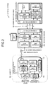
- FIG. 2 is a block diagram of units making up the medical system 1 according to the present embodiment.
- the capsule medical apparatus 10 insertable into the subject 900 includes, for example, the imaging unit 15 that takes images of the inside of the subject 900 and creates data signal containing the in-vivo images (hereinafter, "image data"); an illuminating unit 16 that illuminates the inside of the subject 900 when the imaging unit 15 takes the images; a signal processing unit 12 that processes the image data created by the imaging unit 15 in a predetermined manner; a sending unit 13 that sends the image data processed by the signal processing unit 32 to the receiving device 30A; a control unit 11 that controls the units of the capsule medical apparatus 10; a storage unit 14 that stores therein computer programs, setting data, etc., those necessary for the control unit 11 to control the units; and a power supply unit 17 that supplies a power to each unit of the capsule medical apparatus 10.
- image data data signal containing the in-vivo images
- the control unit 11 operates the units of the capsule medical apparatus 10 in accordance with, for example, the computer programs and the setting data read from the storage unit 14, thereby causing the corresponding unit to, for example, take images or send data.
- the control unit 11 is, for example, a processor such as a CPU (Central Processing Unit) or an MPU (Micro Processing Unit).
- the storage unit 14 stores therein the computer programs to be executed by the control unit 11 and parameters, etc., to be used with the computer programs.
- the storage unit 14 is, for example, a ROM (Read Only Memory). It should be noted that the storage unit 14 can include a RAM (Random Access Memory) on which the computer programs read by the control unit 11 are loaded.
- the imaging unit 15 includes, for example, a light-receiving element 15a that takes images of the inside of the subject 900 and creates the image data containing the images; an objective lens 15b that is at the light-receiving surface side of the light-receiving element 15a; and a driving circuit that drives these elements, being mounted on a not shown circuit board.
- the illuminating unit 16 that illuminates the subject 900 with light for the image capture and its driving circuit are also mounted.
- the driving circuits of the imaging unit 15 and the illuminating unit 16 operate under the control of the control unit 11 so that the image data containing the in-vivo images are acquired, for example, periodically (e.g., two frames per second) and the image data is input to the signal processing unit 12.
- the operation of the capsule medical apparatus 10 during the image capture will be described in detail later.
- each of the imaging unit 15 and the illuminating unit 16 includes its driving circuit.
- the imaging unit 15 and the illuminating unit 16 in the present embodiment are so-called an in-vivo information acquiring unit that acquires the in-vivo information.
- the signal processing unit 12 processes in a predetermined manner, under the control of the control unit 11, the analog image data received from the imaging unit 15, for example, performs sampling, amplification, and A/D (Analog to Digital) conversion, thereby creating digital image data.
- the processed image data is input to the sending unit 13.
- the sending unit 13 processes, under the control of the control unit 11, the image data received from the signal processing unit 12, for example, superimposes the image data onto a reference frequency signal to be sent and performs modulations and up-conversion and then sends the processed image data as a wireless signal out of the capsule medical apparatus 10.
- the units of the capsule medical apparatus 10 is accommodated in, for example, a capsule casing 18.
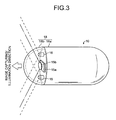
- the casing 18 includes, as shown in FIG. 3 , a container 18a and a cap 18b, the container 18a having one end being hemispherical or dome shaped and the other end being substantially cylindrical shaped with an aperture, the cap 18b being fittable into the aperture of the container 18a for sealing the casing 18.
- the casing 18 is, for example, small enough to be swallowed by the subject 900.
- at least the cap 18b is made of a transparent material.
- the circuit board on which the imaging unit 15 and the illuminating unit 16 are mounted is inside the casing 18 and is closer to the cap 18b.
- each circuit board faces toward the cap 18b. Therefore, as shown in FIGS. 2 and 3 , the image capturing/illumination direction of the imaging unit 15 and the illuminating unit 16 is the direction toward the outside of the capsule medical apparatus 10 through the transparent cap 18b.
- the capsule medical apparatus 10 has one imaging unit 15, the present invention is not limited thereto and a plurality of imaging units and/or a plurality of illuminating units can be used in such a manner that, for example, the container 18a is a cylindrical shape with apertures on both ends, the transparent cap 18b is fit into the aperture on each end, and both the imaging unit 15 and the illuminating unit 16 are arranged at each side.
- the receiving device 30A in the present embodiment is on the outside of the subject 900 (e.g., the outer surface of the subject 900 or the clothes of the subject 900).
- the receiving device 30A includes, as shown in FIG. 2 , a receiving unit 33 that receives the image data from the capsule medical apparatus 10; a signal processing unit 32 that processes the received image data in a predetermined manner; a control unit 31 that controls the units of the receiving device 30A; a storage unit 34 that stores therein computer programs, setting data, etc., those necessary for the control unit 31 to control the units; and a communication unit 35 that functions as an interface to communicate with the later-described information processing apparatus 50.
- the control unit 31 operates the units of the receiving device 30A in accordance with, for example, the computer programs and the setting data read from the storage unit 34, thereby causing the corresponding unit to, for example, send the image data that has been received from the capsule medical apparatus 10 to the information processing apparatus 50.
- the control unit 31 is, for example, a processor such as a CPU or an MPU.
- the storage unit 34 stores therein the computer programs to be executed by the control unit 11 and parameters, etc., to be used with the computer programs.
- the storage unit 34 is, for example, a ROM and/or a RAM.
- the storage unit 34 can be used as an execution area during when the control unit 31 executes the computer programs.
- the receiving unit 33 processes, under the control of the control unit 31, the signal received from the capsule medical apparatus 10 via the outer antenna 20A, for example, performs filtering, down-conversion, demodulation, and decode, and then inputs the processed signal to the signal processing unit 32.
- the signal processing unit 32 Under the control of the control unit 31, the signal processing unit 32 separates the image data from the data signal received from the receiving unit 33, reconfigures the image data, and inputs the reconfigured image data to the communication unit 35. After separating and reconfiguring the image data under the control of the control unit 31, the signal processing unit 32 can store the reconfigured image data in a portable storage unit 36 that is attachable to the receiving device 30A.
- the communication unit 35 makes, under the control of the control unit 31, communications with a communication unit 55 of the information processing apparatus 50, thereby sending/receiving data to/from the information processing apparatus 50, the image data and data signals including request signals and response signals.
- the communication unit 35 is, for example, a USB interface or similar, and is connected to the above-mentioned communication cable 59.
- the communication unit 35 receives a USB bus power via, for example, the communication cable 59.
- the units of the receiving device 30A operate by using the USB bus power as the power source. However, the configuration is not limited thereto and the receiving device 30A can include an internal power source and the units of the receiving device 30A operate by the electric power received from the internal power source.
- the configuration of the information processing apparatus 50 according to the present embodiment is described below in detail with reference to FIG. 2 .
- the information processing apparatus 50 according to the present embodiment is, for example, an information processing apparatus, such as a personal computer having a computing function and a display function. As shown in FIG.
- the information processing apparatus 50 includes the communication unit 55 that is an interface for communications with the receiving device 30A; a signal processing unit 52 that processes in a predetermined manner the image data received via the communication unit 55 and generates an image signal for displaying the image data; a display unit 56 that displays the in-vivo images in accordance with the image signal received from the signal processing unit 52; a control unit 51 that controls the units of the information processing apparatus 50 and performs calculations, etc.; and a storage unit 54 that stores therein computer programs that describe processes to be performed by the control unit 51 and setting data.
- the information processing apparatus 50 for example, receives the in-vivo images from the capsule medical apparatus 10 via the receiving device 30A and then displays the substantially real-time in-vivo images on the display unit 56.
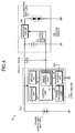
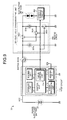
- FIG. 4 is a detailed block diagram of the configuration of the capsule medical apparatus 10 according to the present embodiment.
- the capsule medical apparatus 10 includes a first circuit 110 and a second circuit 120, the first circuit 110 including the control unit 11, the signal processing unit 12, the sending unit 13, the storage unit 14, and the imaging unit 15, and the second circuit 120 including the illuminating unit 16.
- the second circuit 120 further includes an electric storage unit 121 that stores therein a charge and a booster circuit 122 that boosts the electric power to be supplied to the illuminating unit 16.
- a switch SW18 that connects/disconnects between the power supply unit 17/the first circuit 110 and the second circuit 120.
- a control voltage generated by a timing control unit 11a of the control unit 11 is applied to a control terminal of the switch SW18.
- the switch SW18 Upon receiving, for example, a high-level control voltage Vcont, the switch SW18 is switched off and thus the first circuit 110 is disconnected from the second circuit 120.
- the switch SW18 Upon receiving, for example, a low-level control voltage Vcont, the switch SW18 is switched on and thus the first circuit 110 is connected to the second circuit 120.
- the electric storage unit 121 of the second circuit 120 is, for example, a capacitor or a secondly battery.
- the switch SW18 When the switch SW18 is switched on, i.e., the power supply unit 17 is connected to the second circuit 120, a charge is stored in the electric storage unit 121 in accordance with the electric power from the power supply unit 17.
- the switch SW18 is switched off, i.e., the power supply unit 17 is disconnected from the second circuit 120, the electric storage unit 121 supplies the stored charge to the illuminating unit 16 via the booster circuit 122.
- the illuminating unit 16 illuminates.
- the electric storage unit 121 has a capacity large enough to store therein the electric power that is necessary for the illuminating unit 16 to illuminate at least one time.
- the booster circuit 122 boosts the electric power received from the electric storage unit 121 to a level almost the same as the level of a driving voltage for the illuminating unit 16, and the booster circuit 122 is, for example, a charge pomp circuit and a DC-DC converter.
- the booster circuit 122 receives the control voltage Vcont from the timing control unit 11a. During a period when, for example, receiving the certain control voltage Vcont in response to which the switch SW18 is switched off, the booster circuit 122 boosts the electric power received from the electric storage unit 121 and supplies the boosted electric power to the illuminating unit 16.
- the booster circuit 122 can be configured in such a manner that the electric storage unit 121/the power supply unit 17 and the illuminating unit 16 are electrically disconnected from each other during a period when, for example, receiving the certain control voltage Vcont in response to which the switch SW18 is switched on so that the electric power cannot flow from the power supply unit 17 or the electric storage unit 121 to the illuminating unit 16. It is allowable to set a control signal for the switch SW18 and a control signal for the booster circuit 122, respectively, and controls the switch SW18 and the booster circuit 122 individually. In this case, the booster circuit 122 can operate after the switch SW18 is switched off.
- FIG. 5 is a timing chart that illustrates the relations among the control voltage Vcont, the operation of the imaging unit 15, and the operation of the illuminating unit 16 according to the present embodiment.
- the timing control unit 11a outputs the high-level control voltage Vcont at least during a period D1 when the illuminating unit 16 illuminates and the charge is stored in the light-receiving element 15a of the imaging unit 15 (see FIG. 3 ).
- the switch SW18 is switched off and the power supply unit 17 is set disconnected from the second circuit 120.
- the electric power stored in the electric storage unit 121 is supplied to the illuminating unit 16 via the booster circuit 122 and the illuminating unit 16 illuminates.
- the power supply unit 17 is disconnected from the second circuit 120 during this period; therefore, it is possible to suppress a steep decrease in the power-supply voltage that may be caused by the driving of the illuminating unit 16.
- stable operation of the capsule medical apparatus 10 (especially, the first circuit 110) is achieved when the illuminating unit 16 is in operation.
- the timing control unit 11a outputs the low-level control voltage Vcont.
- the switch SW18 is switched on, the first circuit 110 is set connected to the second circuit 120, and the electric power from the power supply unit 17 is stored in the electric storage unit 121.
- the first circuit 110 operates by the electric power received from the power supply unit 17, regardless whether the illuminating unit 16 operates or not.
- the power supply unit 17 (first power supplying unit) that supplies the electric power to the imaging unit 15 is electrically disconnected, by operation of the switch SW18, from the electric storage unit 121 (second power supplying unit) that supplies the electric power to the illuminating unit 16 at least during the illuminating period (D1) of the lighting unit; therefore, it is possible to prevent the voltage of the power supply unit 17 from being unstable during the illuminating period.
- FIG. 6 A reference example of the capsule medical apparatus 10 according to the present embodiment is illustrated in FIG. 6 .
- a capsule medical apparatus 10A shown in FIG. 6 has almost the same configuration as that of the capsule medical apparatus 10 shown in FIG. 4 but both the first circuit 110 and a second circuit 120A have dedicated power supply units, i.e., the power supply unit 17 or a power supply unit 121A, respectively.
- the power supply unit 17 or a power supply unit 121A respectively.
- a medical system according to a second embodiment of the present invention is described in detail below with reference to the drawings.
- the parts the same as those of the medical system 1 according to the above first embodiment are denoted with the same reference number and the detailed description is omitted.
- the medical system according to the present embodiment has almost the same configuration as that of the medical system 1 according to the above first embodiment.
- another apparatus shown in FIG. 7 is used instead of the capsule medical apparatus 10 shown in FIG. 4 according to the first embodiment.
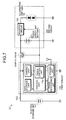
- FIG. 7 is a block diagram of the configuration of a capsule medical apparatus 20 according to the present embodiment.
- the capsule medical apparatus 20 includes an electric storage unit 217 and a second circuit 220 instead of the power supply unit 17 and the second circuit 120 of the capsule medical apparatus 10 shown in FIG. 4 .
- the second circuit 220 includes a power supply unit 221 instead of the electric storage unit 121 of the second circuit 120.
- the other components are the same as those of the capsule medical apparatus 10 shown in FIG. 4 .
- the electric storage unit 217 is, for example, a capacitor or a secondary battery that has a capacity large enough to store therein the electric power necessary for the first circuit 110 to operate during a period when the booster circuit 122 drives the illuminating unit 16.
- the switch SW18 When the switch SW18 is switched on, the electric power from the power supply unit 221 of the second circuit 220 is stored in the electric storage unit 217.
- the switch SW18 when the switch SW18 is switched off, the electric storage unit 217 supplies the stored charge to the first circuit 110.
- FIG. 8 is a timing chart that illustrates the relations among the control voltage Vcont, the operation of the imaging unit 15, and the operation of the illuminating unit 16 according to the present embodiment.
- the timing control unit 11a outputs the high-level control voltage Vcont at least during the period D1 when the illuminating unit 16 illuminates and the charge is stored in the light-receiving element 15a of the imaging unit 15 (see FIG. 3 ).
- the switch SW18 is switched off and the first circuit 110 is set disconnected from the power supply unit 221.
- the electric power stored in the electric storage unit 217 is supplied to the first circuit 110.
- the illuminating unit 16 receives the electric power from the power supply unit 221 via the booster circuit 122.
- the first circuit 110 operates by the electric power received from the electric storage unit 217 and the illuminating unit 16 operates by the electric power received from the power supply unit 221.
- the first circuit 110 is disconnected from the power supply unit 221 during this period; therefore, it is possible to suppress a steep decrease in the voltage of the electric storage unit 217 that may be caused by the driving of the illuminating unit 16.
- stable operation of the capsule medical apparatus 20 (especially, the first circuit 110) is achieved when the illuminating unit 16 is in operation.
- the timing control unit 11a outputs the low-level control voltage Vcont.
- the switch SW18 is switched on and the electric power is supplied from the power supply unit 221 to both the first circuit 110 and the electric storage unit 217. It means that during the period when the illuminating unit 16 is not in operation, the first circuit 110 operates by the electric power received from the electric storage unit 217 and the electric storage unit 217 stores therein the electric power received from the power supply unit 221. It is allowable to set a control signal for the switch SW18 and another control signal for the booster circuit 122, respectively, and controls the switch SW18 and the booster circuit 122 individually. In this case, the booster circuit 122 can operate after the switch SW18 is switched off.
- the electric storage unit 217 (first power supplying unit) that supplies the electric power to the imaging unit 15 is electrically disconnected, by operation of the switch SW18, from the power supply unit 221 (second power supplying unit) that supplies the electric power to the illuminating unit 16 at least during the illuminating period (D1) of the lighting unit; therefore, it is possible to prevent the voltage of the electric storage unit 217 from being unstable during the illuminating period.
- a medical system according to a third embodiment of the present invention is described in detail below with reference to the drawings.
- the parts the same as those of any of the medical systems according to the first and the second embodiments are denoted with the same reference number and the detailed description is omitted.
- FIG. 9 is a block diagram of the configuration of a capsule medical apparatus 30 according to the present embodiment.
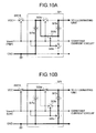
- FIG. 10A is a circuit diagram that illustrates the connection state of an electric storage/boosting unit 321 according to the present embodiment when the control voltage Vcont is at the low level;
- FIG. 10B is a circuit diagram that illustrates the connection state of the electric storage/boosting unit 321 according to the present embodiment when the control voltage Vcont is at the high level.
- the capsule medical apparatus 30 includes a second circuit 320 instead of the second circuit 120 of the capsule medical apparatus 10 shown in FIG. 4 .
- the second circuit 320 includes the electric storage/boosting unit 321 instead of the electric storage unit 121 and the booster circuit 122 and further includes a constant current circuit 323 that controls the current to be input to the illuminating unit 16.
- the other components are the same as those of the capsule medical apparatus 10 shown in FIG. 4 .
- the electric storage/boosting unit 321 includes two capacitors 321a and 321b between a power wire VCC to which a power-supply voltage Vcc is applied and a grounding wire GND at a grounding potential V GND ; and a first switch 322a, a second switch 322b, and a third switch 322c that switch, in accordance with the control voltage Vcont received from the timing control unit 11a, the connection relation between the capacitors 321a and 321b to either the parallel connection to the series connection.
- Each of the capacitors 321a and 321b can be a secondary battery.
- the connection relation is switched as shown in the bold line of FIG. 10A so that the two capacitors 321a and 321b are arranged in series between the grounding wire GND and the illuminating unit 16. Therefore, in this situation, the boosted electric power is applied to the illuminating unit 16 in accordance with the charge stored in the two capacitors 321a and 321b. Thus, the illuminating unit 16 illuminates.
- the broken lines shown in FIG. 10A indicate disconnected and inoperable wires.
- the connection relation of the electric storage/boosting unit 321 is switched as shown in the bold line of FIG. 10B so that the two capacitors 321a and 321b are arranged in parallel between the power wire VCC and the grounding wire GND. Therefore, in this situation, the charge is stored in the two capacitors 321a and 321b.
- the broken lines shown in FIG. 10B indicate disconnected and inoperable wires.
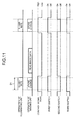
- FIG. 11 is a timing chart that illustrates the relations among the control voltage Vcont, the operation of the imaging unit 15, the operation of the illuminating unit 16, and the operations of the first, second, and third switches 322a to 322c according to the present embodiment.
- the timing control unit 11a outputs the high-level control voltage Vcont at least during the period D1 when the illuminating unit 16 illuminates and the charge is stored in the light-receiving element 15a of the imaging unit 15 (see FIG. 3 ).
- the switch SW18 is switched off, and the power wire VCC between the first circuit 110 and the second circuit 320 is in disconnection.
- the first switch 322a and the third switch 322c are switched on and the second switch 322b is switched off.
- the two capacitors 321a and 321b are connected to each other in series between the grounding wire GND and the illuminating unit 16.
- the illuminating unit 16 receives the boosted electric power from the two capacitors 321a and 321b that are arranged in series.
- the power wire VCC between the first circuit 110 and the second circuit 320 is in disconnection; therefore, it is possible to suppress a steep decrease in the power-supply voltage Vcc that may be caused by the driving of the illuminating unit 16.
- stable operation of the capsule medical apparatus 30 especially, the first circuit 110 is achieved when the illuminating unit 16 is in operation.
- the illuminating unit 16 when the illuminating unit 16 is not in operation as shown in FIG. 11 , for example, when the imaging unit 15 reads the image data from the light-receiving element 15a, the timing control unit 11a outputs the low-level control voltage Vcont.
- the switch SW18 is switched on, the power wire VCC between the first circuit 110 and the second circuit 320 is in connection, and the electric power is supplied from the power supply unit 17 to both the first circuit 110 and the second circuit 320.
- the first switch 322a and the third switch 322c are switched off and the second switch is switched on.
- FIG. 11 when the imaging unit 15 reads the image data from the light-receiving element 15a, the timing control unit 11a outputs the low-level control voltage Vcont.
- the switch SW18 is switched on, the power wire VCC between the first circuit 110 and the second circuit 320 is in connection, and the electric power is supplied from the power supply unit 17 to both the first circuit 110 and the second circuit 320.
- the two capacitors 321a and 321b are connected to each other in parallel between the grounding wire GND and the power wire VCC, and the electric power from the power supply unit 17 is stored in each of the capacitors 321a and 321b.
- the first circuit 110 operates by the electric power received from the power supply unit 17 and the electric storage/boosting unit 321 of the second circuit 320 stores therein the electric power received from the power supply unit 221.
- the constant current circuit 323 is used to adjust, for example, the current in the illuminating unit 16 constant.
- the high-level control voltage Vcont is received from the timing control unit 11a, he constant current circuit 323 adjusts the current so that the illuminating unit 16 receives the constant current.
- the power supply unit 17 (first power supplying unit) that supplies the electric power to the imaging unit 15 is electrically disconnected, by operation of the switch SW18, from the electric storage/boosting unit 321 (second power supplying unit) that supplies the electric power to the illuminating unit 16 at least during the illuminating period (D1) of the lighting unit; therefore, it is possible to prevent the power supply voltage VCC from being unstable during the illuminating period.
Landscapes
- Health & Medical Sciences (AREA)
- Life Sciences & Earth Sciences (AREA)
- Surgery (AREA)
- Engineering & Computer Science (AREA)
- General Health & Medical Sciences (AREA)
- Public Health (AREA)
- Biomedical Technology (AREA)
- Heart & Thoracic Surgery (AREA)
- Medical Informatics (AREA)
- Molecular Biology (AREA)
- Biophysics (AREA)
- Animal Behavior & Ethology (AREA)
- Physics & Mathematics (AREA)
- Veterinary Medicine (AREA)
- Pathology (AREA)
- Nuclear Medicine, Radiotherapy & Molecular Imaging (AREA)
- Optics & Photonics (AREA)
- Radiology & Medical Imaging (AREA)
- Computer Networks & Wireless Communication (AREA)
- Endoscopes (AREA)
- Measurement Of The Respiration, Hearing Ability, Form, And Blood Characteristics Of Living Organisms (AREA)
Abstract
Description
- The present invention relates to a body-insertable apparatus and, more particularly, to a capsule body-insertable apparatus that is insertable into a subject's body and takes images of the inside of the subject's body.
- Capsule body-insertable apparatuses that include an imaging element (hereinafter, "capsule endoscope") have been developed. The capsule endoscopes are insertable into a subject's body via, for example, the oral route, take images of the inside of the subject's body, and wirelessly send the taken images (hereinafter, "in-vivo images") to an external device that is outside of the subject's body. An operator can observe the in-vivo images received by the external device and check subject's symptoms, etc., in order to perform a diagnosis.
- Patent Literature 1: Japanese Laid-open Patent Publication No.
2005-245963 - Generally, the objects imaged by the capsule endoscope are internal organs having a relatively small space such as small intestine. Capturing an image of such objects does not need a large amount of illumination light because a distance between the capsule endoscope and the objects is short. In recent years, however, there are needs to observe internal organs having a relatively large space such as stomach and large intestine. Capturing an image of the internal organs having a relatively large space needs a large amount of illumination light because a distance between the capsule endoscope and the objects is long.
- However, illuminating the inside of the subject with a large amount of light for capturing an image needs a large amount of electrical current for a light source such as a light emitting diode (LED). Accordingly, there is a problem in that when a power supply which supplies power to the other circuits of the capsule endoscope is used for illumination which consumes a large amount of electrical current, the power-supply voltage which is supplied to the other circuits is unstable and thus the other circuits may not work well.
- The present invention has been made in view of the above problem, and an object of the invention is to provide a body-insertable apparatus capable of preventing the power-supply voltage from being unstable during the illuminating period.
- To achieve the object, a body-insertable apparatus according to the present invention includes an illuminating unit that illuminates the inside of a subject's body; an imaging unit that takes an image of the inside of the subject's body; a first power supplying unit that supplies electric power to the imaging unit; a second power supplying unit that supplies electric power to the illuminating unit; and a switch that either connects the first power supplying unit to the second power supplying unit or disconnects the first power supplying unit from the second power supplying unit. The switch electrically separates the first power supplying unit from the second power supplying unit during at least an illuminating period of the illuminating unit.
- In the body-insertable apparatus according to the invention, the second power supplying unit stores therein the electric power received from the first power supplying unit and supplies the stored electric power to the illuminating unit.
- In the body-insertable apparatus according to the invention, the first power supplying unit stores therein the electric power received from the second power supplying unit and supplies the stored electric power to the imaging unit.
- The body-insertable apparatus according to the invention further includes a boosting unit that boosts the electric power received from the second power supplying unit and supplies the boosted electric power to the illuminating unit.
- In the body-insertable apparatus according to the invention, the second power supplying unit includes a plurality of charge storage units and at least one switch that switches a connection state between the charge storage units to either a series connection or a parallel connection, the at least one switch switches the connection state between the charge storage units to the series connection during at least the illuminating period of the illuminating unit, and the at least one switch switches the connection state between the charge storage units to the parallel connection during at least a part of the period other than during the illuminating period of the illuminating unit, and the charge storage units store therein the electric power received from the first power supplying unit during at least the part of the period other than during the illuminating period of the illuminating unit and supplies the stored electric power to the illuminating unit during at least the illuminating period of the illuminating unit.
- In the body-insertable apparatus according to the invention, the first power supplying unit is a primary battery, and the second power supplying unit is a secondary battery or a capacitor that stores therein the electric power received from the first power supplying unit.
- In the body-insertable apparatus according to the invention, the second power supplying unit is a primary battery, and the first power supplying unit is a secondary battery or a capacitor that stores therein the electric power received from the second power supplying unit. Advantageous Effects of Invention
- According to the present invention, the first power supplying unit that supplies the electric power to the imaging unit is electrically disconnected from the second power supplying unit that supplies the electric power to the illuminating unit at least during the period when the illuminating unit illuminates (the illuminating period); therefore, it is possible to provide a body-insertable apparatus that can prevent the power-supply voltage from being unstable during the illuminating period. Brief Description of Drawings
-
-
FIG. 1 is a schematic diagram of the configuration of a medical system according to any of a first, second, or third embodiment of the present invention. -
FIG. 2 is a block diagram of units making up the medical system according to any of the first, second, or third embodiments of the present invention. -
FIG. 3 is an outline view of a capsule medical apparatus according to any of the first, second, or third embodiments of the present invention. -
FIG. 4 is a block diagram of the configuration of the capsule medical apparatus according to the first embodiment of the present invention. -
FIG. 5 is a timing chart that illustrates the relations among a control voltage, the operation of an imaging unit, and the operation of an illuminating unit according to the first embodiment of the present invention. -
FIG. 6 is a block diagram of another embodiment that is compared for reference with the capsule medical apparatus according to the first embodiment of the present invention. -
FIG. 7 is a block diagram of the configuration of a capsule medical apparatus according to the second embodiment of the present invention. -
FIG. 8 is a timing chart that illustrates the relations among the control voltage, the operation of the imaging unit, and the operation of the illuminating unit according to the second embodiment of the present invention. -
FIG. 9 is a block diagram of the configuration of a capsule medical apparatus according to the third embodiment of the present invention. -
FIG. 10A is a circuit diagram that illustrates the connection state of an electric storage/boosting unit according to the third embodiment of the present invention when the control voltage is at a low level. -
FIG. 10B is a circuit diagram that illustrates the connection state of the electric storage/boosting unit according to the third embodiment of the present invention when the control voltage is at a high level. -
FIG. 11 is a timing chart that illustrates the relations among the control voltage, the operation of the imaging unit, the operation of the illuminating unit, and the operation of a first, second, and third switch according to the third embodiment of the present invention. - Exemplary embodiments of the present invention are described in detail below with reference to the accompanying drawings. It should be noted that the present invention is not limited to the following embodiments. Moreover, the shape, the size, and the positional relation of the components described in the following are merely examples to make the contents of the present invention understandable and, therefore, the present invention is not limited to the shape, the size, and the positional relation of the components illustrated in the drawings. Furthermore, in some cross-sections of the drawings, some sections are not hatched for clarity. Moreover, the numerical values described in the following are merely examples and, therefore, the present invention is not limited to these numerical values.
- The configuration and operation of a
medical system 1 according to a first embodiment of the present invention is described below with reference to the drawings. In the present embodiment, as an example of a body-insertable apparatus, a capsulemedical apparatus 10 is used that is insertable into asubject 900 via the oral route and acquires information about the inside of the subject 900 (in-vivo information) while moving from the esophagus to the anus of thesubject 900. It should be noted that the present invention is not limited thereto and some other capsule medical apparatuses can be used as a body-insertable apparatus of the present invention, for example, a medical device that acquires in-vivo information from thesubject 900 while floating on liquid accommodated in organs, such as the stomach and the bowel. Moreover, as an example of the in-vivo information acquired by the capsulemedical apparatus 10, images (in-vivo images) taken by a later-describedimaging unit 15 are used in the present embodiment. However, the present invention is not limited thereto and some other types of information can be used, for example, the inner temperature, the inner pressure, the inner pH level of the subject. -
FIG. 1 is a schematic diagram of the configuration of themedical system 1 according to the present embodiment. As shown inFIG. 1 , themedical system 1 includes the capsulemedical apparatus 10 small enough to be swallowed by thesubject 900, a receivingdevice 30A that can receive image data containing the in-vivo images sent as wireless signals from the capsulemedical apparatus 10, and aninformation processing apparatus 50 that can wirelessly or via a wire receive/send data from/to thereceiving device 30A. - The
receiving device 30A is connected to anouter antenna 20A via a connectingcable 39, a not shown balun (Balun), or similar. The wireless signal sent from the capsulemedical apparatus 10 is received by thereceiving device 30A via theouter antenna 20A. - The
receiving device 30A is connected to theinformation processing apparatus 50 via, for example, a serial line or a parallel line. In the present embodiment, a USB interface is used to connect thereceiving device 30A to theinformation processing apparatus 50 and thereceiving device 30A is connected to theinformation processing apparatus 50 via acommunication cable 59 that is a USB cable. It should be noted that the present invention is not limited thereto and thereceiving device 30A can be connected to theinformation processing apparatus 50 in different connection methods, for example, via a card-type interface for a PC (Personal Computer) or the Bluetooth (registered trademark). - Moreover, the capsule
medical apparatus 10 takes in-vivo images, for example, periodically and sends the image data to thereceiving device 30A sequentially. Therefore, if theinformation processing apparatus 50 periodically repeats the process of receiving the image data from thereceiving device 30A and displaying the image data thereon over and over, theinformation processing apparatus 50 can display substantially real-time in-vivo images for the user. If the image capturing cycle of the capsulemedical apparatus 10 is set to, for example, two frames per second, theinformation processing apparatus 50 receives the image data from thereceiving device 30A at least two times every second and displays the image data. This enables the substantially real-time in-vivo image display. The process in which theinformation processing apparatus 50 receives the image data from the receivingdevice 30A will be described in detail later. - The
medical system 1 according to the present embodiment is described in detail below with reference to the block diagram ofFIG. 2. FIG. 2 is a block diagram of units making up themedical system 1 according to the present embodiment. - As shown in
FIG. 2 , the capsulemedical apparatus 10 insertable into the subject 900 includes, for example, theimaging unit 15 that takes images of the inside of the subject 900 and creates data signal containing the in-vivo images (hereinafter, "image data"); an illuminatingunit 16 that illuminates the inside of the subject 900 when theimaging unit 15 takes the images; asignal processing unit 12 that processes the image data created by theimaging unit 15 in a predetermined manner; a sendingunit 13 that sends the image data processed by thesignal processing unit 32 to the receivingdevice 30A; acontrol unit 11 that controls the units of the capsulemedical apparatus 10; astorage unit 14 that stores therein computer programs, setting data, etc., those necessary for thecontrol unit 11 to control the units; and apower supply unit 17 that supplies a power to each unit of the capsulemedical apparatus 10. - The
control unit 11 operates the units of the capsulemedical apparatus 10 in accordance with, for example, the computer programs and the setting data read from thestorage unit 14, thereby causing the corresponding unit to, for example, take images or send data. Thecontrol unit 11 is, for example, a processor such as a CPU (Central Processing Unit) or an MPU (Micro Processing Unit). - The
storage unit 14 stores therein the computer programs to be executed by thecontrol unit 11 and parameters, etc., to be used with the computer programs. Thestorage unit 14 is, for example, a ROM (Read Only Memory). It should be noted that thestorage unit 14 can include a RAM (Random Access Memory) on which the computer programs read by thecontrol unit 11 are loaded. - As shown in
FIG. 3 , theimaging unit 15 includes, for example, a light-receivingelement 15a that takes images of the inside of the subject 900 and creates the image data containing the images; anobjective lens 15b that is at the light-receiving surface side of the light-receivingelement 15a; and a driving circuit that drives these elements, being mounted on a not shown circuit board. On the circuit board, the illuminatingunit 16 that illuminates the subject 900 with light for the image capture and its driving circuit are also mounted. The driving circuits of theimaging unit 15 and the illuminatingunit 16 operate under the control of thecontrol unit 11 so that the image data containing the in-vivo images are acquired, for example, periodically (e.g., two frames per second) and the image data is input to thesignal processing unit 12. The operation of the capsulemedical apparatus 10 during the image capture will be described in detail later. Moreover, in the following, it is assumed that each of theimaging unit 15 and the illuminatingunit 16 includes its driving circuit. Moreover, theimaging unit 15 and the illuminatingunit 16 in the present embodiment are so-called an in-vivo information acquiring unit that acquires the in-vivo information. - The
signal processing unit 12 processes in a predetermined manner, under the control of thecontrol unit 11, the analog image data received from theimaging unit 15, for example, performs sampling, amplification, and A/D (Analog to Digital) conversion, thereby creating digital image data. The processed image data is input to the sendingunit 13. - The sending
unit 13 processes, under the control of thecontrol unit 11, the image data received from thesignal processing unit 12, for example, superimposes the image data onto a reference frequency signal to be sent and performs modulations and up-conversion and then sends the processed image data as a wireless signal out of the capsulemedical apparatus 10. - As shown in
FIGS. 2 and3 , the units of the capsulemedical apparatus 10 is accommodated in, for example, acapsule casing 18. Thecasing 18 includes, as shown inFIG. 3 , acontainer 18a and acap 18b, thecontainer 18a having one end being hemispherical or dome shaped and the other end being substantially cylindrical shaped with an aperture, thecap 18b being fittable into the aperture of thecontainer 18a for sealing thecasing 18. Thecasing 18 is, for example, small enough to be swallowed by the subject 900. Moreover, in the present embodiment, at least thecap 18b is made of a transparent material.
The circuit board on which theimaging unit 15 and the illuminatingunit 16 are mounted is inside thecasing 18 and is closer to thecap 18b. The element supporting surface of each circuit board faces toward thecap 18b. Therefore, as shown inFIGS. 2 and3 , the image capturing/illumination direction of theimaging unit 15 and the illuminatingunit 16 is the direction toward the outside of the capsulemedical apparatus 10 through thetransparent cap 18b. - Although, in the present embodiment, the capsule
medical apparatus 10 has oneimaging unit 15, the present invention is not limited thereto and a plurality of imaging units and/or a plurality of illuminating units can be used in such a manner that, for example, thecontainer 18a is a cylindrical shape with apertures on both ends, thetransparent cap 18b is fit into the aperture on each end, and both theimaging unit 15 and the illuminatingunit 16 are arranged at each side. - Moreover, the receiving
device 30A in the present embodiment is on the outside of the subject 900 (e.g., the outer surface of the subject 900 or the clothes of the subject 900). The receivingdevice 30A includes, as shown inFIG. 2 , a receivingunit 33 that receives the image data from the capsulemedical apparatus 10; asignal processing unit 32 that processes the received image data in a predetermined manner; acontrol unit 31 that controls the units of the receivingdevice 30A; astorage unit 34 that stores therein computer programs, setting data, etc., those necessary for thecontrol unit 31 to control the units; and acommunication unit 35 that functions as an interface to communicate with the later-describedinformation processing apparatus 50. - The
control unit 31 operates the units of the receivingdevice 30A in accordance with, for example, the computer programs and the setting data read from thestorage unit 34, thereby causing the corresponding unit to, for example, send the image data that has been received from the capsulemedical apparatus 10 to theinformation processing apparatus 50. Thecontrol unit 31 is, for example, a processor such as a CPU or an MPU. - The
storage unit 34 stores therein the computer programs to be executed by thecontrol unit 11 and parameters, etc., to be used with the computer programs. Thestorage unit 34 is, for example, a ROM and/or a RAM. Thestorage unit 34 can be used as an execution area during when thecontrol unit 31 executes the computer programs. - The receiving
unit 33 processes, under the control of thecontrol unit 31, the signal received from the capsulemedical apparatus 10 via theouter antenna 20A, for example, performs filtering, down-conversion, demodulation, and decode, and then inputs the processed signal to thesignal processing unit 32. - Under the control of the
control unit 31, thesignal processing unit 32 separates the image data from the data signal received from the receivingunit 33, reconfigures the image data, and inputs the reconfigured image data to thecommunication unit 35. After separating and reconfiguring the image data under the control of thecontrol unit 31, thesignal processing unit 32 can store the reconfigured image data in aportable storage unit 36 that is attachable to the receivingdevice 30A. - The
communication unit 35 makes, under the control of thecontrol unit 31, communications with a communication unit 55 of theinformation processing apparatus 50, thereby sending/receiving data to/from theinformation processing apparatus 50, the image data and data signals including request signals and response signals. Thecommunication unit 35 is, for example, a USB interface or similar, and is connected to the above-mentionedcommunication cable 59. Thecommunication unit 35 receives a USB bus power via, for example, thecommunication cable 59. The units of the receivingdevice 30A operate by using the USB bus power as the power source. However, the configuration is not limited thereto and the receivingdevice 30A can include an internal power source and the units of the receivingdevice 30A operate by the electric power received from the internal power source. - The configuration of the
information processing apparatus 50 according to the present embodiment is described below in detail with reference toFIG. 2 . Theinformation processing apparatus 50 according to the present embodiment is, for example, an information processing apparatus, such as a personal computer having a computing function and a display function. As shown inFIG. 2 , theinformation processing apparatus 50 includes the communication unit 55 that is an interface for communications with the receivingdevice 30A; a signal processing unit 52 that processes in a predetermined manner the image data received via the communication unit 55 and generates an image signal for displaying the image data; adisplay unit 56 that displays the in-vivo images in accordance with the image signal received from the signal processing unit 52; acontrol unit 51 that controls the units of theinformation processing apparatus 50 and performs calculations, etc.; and astorage unit 54 that stores therein computer programs that describe processes to be performed by thecontrol unit 51 and setting data. Theinformation processing apparatus 50, for example, receives the in-vivo images from the capsulemedical apparatus 10 via the receivingdevice 30A and then displays the substantially real-time in-vivo images on thedisplay unit 56. - The operation of the capsule
medical apparatus 10 according to the present embodiment during the image capture is described below with reference to the drawings.FIG. 4 is a detailed block diagram of the configuration of the capsulemedical apparatus 10 according to the present embodiment. - As shown in
FIG. 4 , the capsulemedical apparatus 10 includes afirst circuit 110 and asecond circuit 120, thefirst circuit 110 including thecontrol unit 11, thesignal processing unit 12, the sendingunit 13, thestorage unit 14, and theimaging unit 15, and thesecond circuit 120 including the illuminatingunit 16. Thesecond circuit 120 further includes anelectric storage unit 121 that stores therein a charge and abooster circuit 122 that boosts the electric power to be supplied to the illuminatingunit 16. - Between the
first circuit 110 and thesecond circuit 120, there is provided a switch SW18 that connects/disconnects between thepower supply unit 17/thefirst circuit 110 and thesecond circuit 120. A control voltage generated by atiming control unit 11a of thecontrol unit 11 is applied to a control terminal of the switch SW18. Upon receiving, for example, a high-level control voltage Vcont, the switch SW18 is switched off and thus thefirst circuit 110 is disconnected from thesecond circuit 120. Upon receiving, for example, a low-level control voltage Vcont, the switch SW18 is switched on and thus thefirst circuit 110 is connected to thesecond circuit 120. - The
electric storage unit 121 of thesecond circuit 120 is, for example, a capacitor or a secondly battery. When the switch SW18 is switched on, i.e., thepower supply unit 17 is connected to thesecond circuit 120, a charge is stored in theelectric storage unit 121 in accordance with the electric power from thepower supply unit 17. On the other hand, when the switch SW18 is switched off, i.e., thepower supply unit 17 is disconnected from thesecond circuit 120, theelectric storage unit 121 supplies the stored charge to the illuminatingunit 16 via thebooster circuit 122. Thus, the illuminatingunit 16 illuminates. Theelectric storage unit 121 has a capacity large enough to store therein the electric power that is necessary for the illuminatingunit 16 to illuminate at least one time. - The
booster circuit 122 boosts the electric power received from theelectric storage unit 121 to a level almost the same as the level of a driving voltage for the illuminatingunit 16, and thebooster circuit 122 is, for example, a charge pomp circuit and a DC-DC converter. Thebooster circuit 122 receives the control voltage Vcont from thetiming control unit 11a. During a period when, for example, receiving the certain control voltage Vcont in response to which the switch SW18 is switched off, thebooster circuit 122 boosts the electric power received from theelectric storage unit 121 and supplies the boosted electric power to the illuminatingunit 16. Thebooster circuit 122 can be configured in such a manner that theelectric storage unit 121/thepower supply unit 17 and the illuminatingunit 16 are electrically disconnected from each other during a period when, for example, receiving the certain control voltage Vcont in response to which the switch SW18 is switched on so that the electric power cannot flow from thepower supply unit 17 or theelectric storage unit 121 to the illuminatingunit 16. It is allowable to set a control signal for the switch SW18 and a control signal for thebooster circuit 122, respectively, and controls the switch SW18 and thebooster circuit 122 individually. In this case, thebooster circuit 122 can operate after the switch SW18 is switched off. - The control voltage Vcont that is used to control both the switch SW18 and the
booster circuit 122 is described with reference to the drawings.FIG. 5 is a timing chart that illustrates the relations among the control voltage Vcont, the operation of theimaging unit 15, and the operation of the illuminatingunit 16 according to the present embodiment. - As shown in
FIG. 5 , thetiming control unit 11a outputs the high-level control voltage Vcont at least during a period D1 when the illuminatingunit 16 illuminates and the charge is stored in the light-receivingelement 15a of the imaging unit 15 (seeFIG. 3 ). Thus, the switch SW18 is switched off and thepower supply unit 17 is set disconnected from thesecond circuit 120. As a result, the electric power stored in theelectric storage unit 121 is supplied to the illuminatingunit 16 via thebooster circuit 122 and the illuminatingunit 16 illuminates. Thepower supply unit 17 is disconnected from thesecond circuit 120 during this period; therefore, it is possible to suppress a steep decrease in the power-supply voltage that may be caused by the driving of the illuminatingunit 16. As a result, stable operation of the capsule medical apparatus 10 (especially, the first circuit 110) is achieved when the illuminatingunit 16 is in operation. - On the other hand, when the illuminating
unit 16 is not in operation, for example, when theimaging unit 15 reads the image data from the light-receivingelement 15a, thetiming control unit 11a outputs the low-level control voltage Vcont. Thus, the switch SW18 is switched on, thefirst circuit 110 is set connected to thesecond circuit 120, and the electric power from thepower supply unit 17 is stored in theelectric storage unit 121. Thefirst circuit 110 operates by the electric power received from thepower supply unit 17, regardless whether the illuminatingunit 16 operates or not. - With the above configuration and operation, in the present embodiment, the power supply unit 17 (first power supplying unit) that supplies the electric power to the
imaging unit 15 is electrically disconnected, by operation of the switch SW18, from the electric storage unit 121 (second power supplying unit) that supplies the electric power to the illuminatingunit 16 at least during the illuminating period (D1) of the lighting unit; therefore, it is possible to prevent the voltage of thepower supply unit 17 from being unstable during the illuminating period. - A reference example of the capsule
medical apparatus 10 according to the present embodiment is illustrated inFIG. 6 . A capsulemedical apparatus 10A shown inFIG. 6 has almost the same configuration as that of the capsulemedical apparatus 10 shown inFIG. 4 but both thefirst circuit 110 and a second circuit 120A have dedicated power supply units, i.e., thepower supply unit 17 or apower supply unit 121A, respectively. As is shown, it is possible to have separated power sources for the illuminatingunit 16 and the other circuits (11, 12, 13, 14, and 15). - A medical system according to a second embodiment of the present invention is described in detail below with reference to the drawings. In the following description, the parts the same as those of the
medical system 1 according to the above first embodiment are denoted with the same reference number and the detailed description is omitted. - The medical system according to the present embodiment has almost the same configuration as that of the
medical system 1 according to the above first embodiment. In the present embodiment, another apparatus shown inFIG. 7 is used instead of the capsulemedical apparatus 10 shown inFIG. 4 according to the first embodiment.FIG. 7 is a block diagram of the configuration of a capsulemedical apparatus 20 according to the present embodiment. - As shown in
FIG. 7 , the capsulemedical apparatus 20 according to the present embodiment includes anelectric storage unit 217 and asecond circuit 220 instead of thepower supply unit 17 and thesecond circuit 120 of the capsulemedical apparatus 10 shown inFIG. 4 . Thesecond circuit 220 includes apower supply unit 221 instead of theelectric storage unit 121 of thesecond circuit 120. The other components are the same as those of the capsulemedical apparatus 10 shown inFIG. 4 . - The
electric storage unit 217 is, for example, a capacitor or a secondary battery that has a capacity large enough to store therein the electric power necessary for thefirst circuit 110 to operate during a period when thebooster circuit 122 drives the illuminatingunit 16. When the switch SW18 is switched on, the electric power from thepower supply unit 221 of thesecond circuit 220 is stored in theelectric storage unit 217. On the other hand, when the switch SW18 is switched off, theelectric storage unit 217 supplies the stored charge to thefirst circuit 110. - The control voltage Vcont according to the present embodiment is described in detail with reference to the drawings.
FIG. 8 is a timing chart that illustrates the relations among the control voltage Vcont, the operation of theimaging unit 15, and the operation of the illuminatingunit 16 according to the present embodiment. - As shown in
FIG. 8 , thetiming control unit 11a outputs the high-level control voltage Vcont at least during the period D1 when the illuminatingunit 16 illuminates and the charge is stored in the light-receivingelement 15a of the imaging unit 15 (seeFIG. 3 ). Thus, the switch SW18 is switched off and thefirst circuit 110 is set disconnected from thepower supply unit 221. As a result, the electric power stored in theelectric storage unit 217 is supplied to thefirst circuit 110. The illuminatingunit 16 receives the electric power from thepower supply unit 221 via thebooster circuit 122. Thus, at least during the period when the illuminatingunit 16 is in operation, thefirst circuit 110 operates by the electric power received from theelectric storage unit 217 and the illuminatingunit 16 operates by the electric power received from thepower supply unit 221. Thefirst circuit 110 is disconnected from thepower supply unit 221 during this period; therefore, it is possible to suppress a steep decrease in the voltage of theelectric storage unit 217 that may be caused by the driving of the illuminatingunit 16. As a result, stable operation of the capsule medical apparatus 20 (especially, the first circuit 110) is achieved when the illuminatingunit 16 is in operation. - On the other hand, when the illuminating
unit 16 is not in operation, for example, when theimaging unit 15 reads the image data from the light-receivingelement 15a, thetiming control unit 11a outputs the low-level control voltage Vcont. Thus, the switch SW18 is switched on and the electric power is supplied from thepower supply unit 221 to both thefirst circuit 110 and theelectric storage unit 217. It means that during the period when the illuminatingunit 16 is not in operation, thefirst circuit 110 operates by the electric power received from theelectric storage unit 217 and theelectric storage unit 217 stores therein the electric power received from thepower supply unit 221. It is allowable to set a control signal for the switch SW18 and another control signal for thebooster circuit 122, respectively, and controls the switch SW18 and thebooster circuit 122 individually. In this case, thebooster circuit 122 can operate after the switch SW18 is switched off. - With the above configuration and operation, in the present embodiment, the electric storage unit 217 (first power supplying unit) that supplies the electric power to the
imaging unit 15 is electrically disconnected, by operation of the switch SW18, from the power supply unit 221 (second power supplying unit) that supplies the electric power to the illuminatingunit 16 at least during the illuminating period (D1) of the lighting unit; therefore, it is possible to prevent the voltage of theelectric storage unit 217 from being unstable during the illuminating period. - A medical system according to a third embodiment of the present invention is described in detail below with reference to the drawings. In the following description, the parts the same as those of any of the medical systems according to the first and the second embodiments are denoted with the same reference number and the detailed description is omitted.
- The medical system according to the present embodiment has almost the same configuration as that of the
medical system 1 according to the above first embodiment. In the present embodiment, another apparatus shown inFIG. 9 is used instead of the capsulemedical apparatus 10 shown inFIG. 4 according to the first embodiment.FIG. 9 is a block diagram of the configuration of a capsulemedical apparatus 30 according to the present embodiment.FIG. 10A is a circuit diagram that illustrates the connection state of an electric storage/boostingunit 321 according to the present embodiment when the control voltage Vcont is at the low level;FIG. 10B is a circuit diagram that illustrates the connection state of the electric storage/boostingunit 321 according to the present embodiment when the control voltage Vcont is at the high level. - As shown in
FIG. 9 , the capsulemedical apparatus 30 according to the present embodiment includes asecond circuit 320 instead of thesecond circuit 120 of the capsulemedical apparatus 10 shown inFIG. 4 . Moreover, thesecond circuit 320 includes the electric storage/boostingunit 321 instead of theelectric storage unit 121 and thebooster circuit 122 and further includes a constantcurrent circuit 323 that controls the current to be input to the illuminatingunit 16. The other components are the same as those of the capsulemedical apparatus 10 shown inFIG. 4 . - As shown in
FIG. 9 , the electric storage/boostingunit 321 includes twocapacitors first switch 322a, asecond switch 322b, and athird switch 322c that switch, in accordance with the control voltage Vcont received from thetiming control unit 11a, the connection relation between thecapacitors capacitors - When, for example, the first, second, and
third switches 322a to 322c receive the low-level control voltage Vcont, i.e., when the switch SW18 is switched off and thepower supply unit 17 is disconnected from thesecond circuit 320, the connection relation is switched as shown in the bold line ofFIG. 10A so that the twocapacitors unit 16. Therefore, in this situation, the boosted electric power is applied to the illuminatingunit 16 in accordance with the charge stored in the twocapacitors unit 16 illuminates. The broken lines shown inFIG. 10A indicate disconnected and inoperable wires. - On the other hand, when, for example, the first, second, and
third switches 322a to 322c receive the high-level control voltage Vcont, i.e., when the switch SW18 (seeFIG. 4 ) is switched on and thepower supply unit 17 is connected to thesecond circuit 320, the connection relation of the electric storage/boostingunit 321 is switched as shown in the bold line ofFIG. 10B so that the twocapacitors capacitors FIG. 10B indicate disconnected and inoperable wires. - The control voltage Vcont according to the present embodiment is described in detail below with reference to the drawings.
FIG. 11 is a timing chart that illustrates the relations among the control voltage Vcont, the operation of theimaging unit 15, the operation of the illuminatingunit 16, and the operations of the first, second, andthird switches 322a to 322c according to the present embodiment. - As shown in
FIG. 11 , thetiming control unit 11a outputs the high-level control voltage Vcont at least during the period D1 when the illuminatingunit 16 illuminates and the charge is stored in the light-receivingelement 15a of the imaging unit 15 (seeFIG. 3 ). Thus, the switch SW18 is switched off, and the power wire VCC between thefirst circuit 110 and thesecond circuit 320 is in disconnection. In this situation, thefirst switch 322a and thethird switch 322c are switched on and thesecond switch 322b is switched off. Thus, as shown inFIG. 10A , the twocapacitors unit 16. Therefore, the illuminatingunit 16 receives the boosted electric power from the twocapacitors first circuit 110 and thesecond circuit 320 is in disconnection; therefore, it is possible to suppress a steep decrease in the power-supply voltage Vcc that may be caused by the driving of the illuminatingunit 16. As a result, stable operation of the capsule medical apparatus 30 (especially, the first circuit 110) is achieved when the illuminatingunit 16 is in operation. - On the other hand, when the illuminating
unit 16 is not in operation as shown inFIG. 11 , for example, when theimaging unit 15 reads the image data from the light-receivingelement 15a, thetiming control unit 11a outputs the low-level control voltage Vcont. Thus, the switch SW18 is switched on, the power wire VCC between thefirst circuit 110 and thesecond circuit 320 is in connection, and the electric power is supplied from thepower supply unit 17 to both thefirst circuit 110 and thesecond circuit 320. In this situation, thefirst switch 322a and thethird switch 322c are switched off and the second switch is switched on. Thus, as shown inFIG. 10B , the twocapacitors power supply unit 17 is stored in each of thecapacitors unit 16 is not in operation, thefirst circuit 110 operates by the electric power received from thepower supply unit 17 and the electric storage/boostingunit 321 of thesecond circuit 320 stores therein the electric power received from thepower supply unit 221. - The constant
current circuit 323 is used to adjust, for example, the current in the illuminatingunit 16 constant. When, for example, the high-level control voltage Vcont is received from thetiming control unit 11a, he constantcurrent circuit 323 adjusts the current so that the illuminatingunit 16 receives the constant current. - With the above configuration and operation, in the present embodiment, the power supply unit 17 (first power supplying unit) that supplies the electric power to the
imaging unit 15 is electrically disconnected, by operation of the switch SW18, from the electric storage/boosting unit 321 (second power supplying unit) that supplies the electric power to the illuminatingunit 16 at least during the illuminating period (D1) of the lighting unit; therefore, it is possible to prevent the power supply voltage VCC from being unstable during the illuminating period. - The embodiments as described above are just examples of the present invention and thus do not limit the invention. It should be obvious that the above description could make the various changes according to specifications and the like within the scope of the invention and other various embodiments within the scope of the invention. Reference Signs List
-
- 1 MEDICAL SYSTEM
- 10, 20, 30 CAPSULE MEDICAL APPARATUS
- 10A CAPSULE MEDICAL APPARATUS
- 11, 31, 51 CONTROL UNIT
- 11a TIMING CONTROL UNIT
- 12, 32, 52 SIGNAL PROCESSING UNIT
- 13 SENDING UNIT
- 14 STORAGE UNIT
- 15 IMAGING UNIT
- 15a LIGHT-RECEIVING ELEMENT
- 15b OBJECTIVE LENS
- 16 ILLUMINATING UNIT
- 17, 121A, 221 POWER SUPPLY UNIT
- 18 CASING
- 18a CONTAINER
- 18b CAP
- 20A OUTER ANTENNA
- 30A RECEIVING DEVICE
- 33 RECEIVING UNIT
- 34 STORAGE UNIT
- 35, 55 COMMUNICATION UNIT
- 36 STORAGE UNIT
- 39 CONNECTING CABLE
- 50 INFORMATION PROCESSING APPARATUS
- 54 STORAGE UNIT
- 56 DISPLAY UNIT
- 59 CONNECTING CABLE
- D1 PERIOD
- 110 FIRST CIRCUIT
- 120, 120A, 220, 320 SECOND CIRCUIT
- 121, 217 ELECTRIC STORAGE UNIT
- 122 BOOSTER CIRCUIT
- 321 ELECTRIC STORAGE/BOOSTING UNIT
- 321a, 321b CAPACITOR
- 322a to 322c FIRST TO THIRD SWITCHES
- 323 CONSTANT CURRENT CIRCUIT
- GND GROUDING WIRE
- SW18 SWITCH
- VCC POWER WIRE
- Vcc POWER-SUPPLY VOLTAGE
- Vcont CONTROL VOLTAGE
Claims (7)
- A body-insertable apparatus comprising:an illuminating unit that illuminates the inside of a subject's body;an imaging unit that takes an image of the inside of the subject's body;a first power supplying unit that supplies electric power to the imaging unit;a second power supplying unit that supplies electric power to the illuminating unit; anda switch that either connects the first power supplying unit to the second power supplying unit or disconnects the first power supplying unit from the second power supplying unit, whereinthe switch electrically separates the first power supplying unit from the second power supplying unit during at least an illuminating period of the illuminating unit.
- The body-insertable apparatus according to claim 1, wherein
the second power supplying unit stores therein the electric power received from the first power supplying unit and supplies the stored electric power to the illuminating unit. - The body-insertable apparatus according to claim 1, wherein
the first power supplying unit stores therein the electric power received from the second power supplying unit and supplies the stored electric power to the imaging unit. - The body-insertable apparatus according to any one of claims 1 to 3, further comprising a boosting unit that boosts the electric power received from the second power supplying unit and supplies the boosted electric power to the illuminating unit.
- The body-insertable apparatus according to claim 1, wherein
the second power supplying unit includes a plurality of charge storage units and at least one switch that switches a connection state between the charge storage units to either a series connection or a parallel connection,
the at least one switch switches the connection state between the charge storage units to the series connection during at least the illuminating period of the illuminating unit, and the at least one switch switches the connection state between the charge storage units to the parallel connection during at least a part of the period other than during the illuminating period of the illuminating unit, and
the charge storage units store therein the electric power received from the first power supplying unit during at least the part of the period other than during the illuminating period of the illuminating unit and supplies the stored electric power to the illuminating unit during at least the illuminating period of the illuminating unit. - The body-insertable apparatus according to claim 1 or 2, wherein
the first power supplying unit is a primary battery,
and
the second power supplying unit is a secondary battery or a capacitor that stores therein the electric power received from the first power supplying unit. - The body-insertable apparatus according to claim 1 or 2, wherein
the second power supplying unit is a primary battery,
and
the first power supplying unit is a secondary battery or a capacitor that stores therein the electric power received from the second power supplying unit.
Applications Claiming Priority (2)
| Application Number | Priority Date | Filing Date | Title |
|---|---|---|---|
| JP2008324137 | 2008-12-19 | ||
| PCT/JP2009/070696 WO2010071075A1 (en) | 2008-12-19 | 2009-12-10 | Device for introduction into a subject |
Publications (2)
| Publication Number | Publication Date |
|---|---|
| EP2359740A1 true EP2359740A1 (en) | 2011-08-24 |
| EP2359740A4 EP2359740A4 (en) | 2015-12-23 |
Family
ID=42268745
Family Applications (1)
| Application Number | Title | Priority Date | Filing Date |
|---|---|---|---|
| EP09833378.4A Withdrawn EP2359740A4 (en) | 2008-12-19 | 2009-12-10 | Device for introduction into a subject |
Country Status (5)
| Country | Link |
|---|---|
| US (1) | US8128556B2 (en) |
| EP (1) | EP2359740A4 (en) |
| JP (1) | JP4718647B2 (en) |
| CN (1) | CN102245077B (en) |
| WO (1) | WO2010071075A1 (en) |
Families Citing this family (4)
| Publication number | Priority date | Publication date | Assignee | Title |
|---|---|---|---|---|
| BR112016024300B1 (en) | 2014-04-21 | 2021-12-14 | Winnow Solutions Limited | FOOD WASTE MONITORING SYSTEM AND FOOD WASTE DISPOSAL MONITORING METHOD |
| WO2017022257A1 (en) * | 2015-07-31 | 2017-02-09 | オリンパス株式会社 | Capsule type endoscope |
| WO2020202531A1 (en) * | 2019-04-04 | 2020-10-08 | オリンパス株式会社 | Receiver system |
| US12273105B2 (en) * | 2022-04-28 | 2025-04-08 | Olympus Medical Systems Corp. | Voltage generation circuit, image sensor, scope, and voltage generation method |
Family Cites Families (18)
| Publication number | Priority date | Publication date | Assignee | Title |
|---|---|---|---|---|
| JP2000066117A (en) * | 1998-08-26 | 2000-03-03 | Asahi Optical Co Ltd | Light source device for endoscope and method of using endoscope system having light source device for endoscope |
| US7772786B2 (en) * | 1999-12-02 | 2010-08-10 | Olympus Corporation | Battery-powered light source device for endoscope |
| US6563269B2 (en) * | 1999-12-06 | 2003-05-13 | Mark I. Robinett | Rechargeable portable light with multiple charging systems |
| JP2001224553A (en) * | 2000-02-17 | 2001-08-21 | Asahi Optical Co Ltd | Imaging device for capsule endoscope |
| US6595756B2 (en) | 2001-09-07 | 2003-07-22 | Medtronic Minimed, Inc. | Electronic control system and process for electromagnetic pump |
| US7473218B2 (en) | 2002-08-06 | 2009-01-06 | Olympus Corporation | Assembling method of capsule medical apparatus |
| JP2004065575A (en) * | 2002-08-06 | 2004-03-04 | Olympus Corp | Capsule type endoscope and assembling method therefor |
| US20040236181A1 (en) * | 2003-04-01 | 2004-11-25 | Olympus Corporation | In-body information acquiring apparatus and power-supply circuit |
| JP2005000552A (en) * | 2003-06-13 | 2005-01-06 | Olympus Corp | Capsule endoscope |
| JP2005152209A (en) * | 2003-11-25 | 2005-06-16 | Olympus Corp | Endoscope device |
| US20070171180A1 (en) * | 2004-02-12 | 2007-07-26 | Takashi Akiyama | Light source driving circuit, lighting apparatus, display apparatus, field sequential color liquid crystal display apparatus, and information appliance |
| JP4426875B2 (en) | 2004-03-08 | 2010-03-03 | オリンパス株式会社 | Capsule medical device magnetic guidance system |
| US20080122291A1 (en) * | 2004-10-19 | 2008-05-29 | Rohm Co., Ltd | Switching Power Supply Control Circuit, Switching Power Supply Device and Electronic Apparatus Employing the Same |
| WO2006095420A1 (en) * | 2005-03-09 | 2006-09-14 | Olympus Corporation | Device to be introduced into subject and system to be introduced into subject |
| US20070260116A1 (en) * | 2005-08-29 | 2007-11-08 | Olympus Corporation And Olympus Medical Systems Corp. | Body-insertable apparatus and receiving apparatus for recognizing remaining power amount |
| JP4891668B2 (en) * | 2006-06-26 | 2012-03-07 | オリンパスメディカルシステムズ株式会社 | Capsule endoscope |
| US7598706B2 (en) * | 2007-01-26 | 2009-10-06 | General Electric Company | Cell balancing battery pack and method of balancing the cells of a battery |
| JPWO2009031640A1 (en) * | 2007-09-07 | 2010-12-16 | オリンパスメディカルシステムズ株式会社 | In vivo information acquisition apparatus and power supply control method |
-
2009
- 2009-12-10 WO PCT/JP2009/070696 patent/WO2010071075A1/en not_active Ceased
- 2009-12-10 EP EP09833378.4A patent/EP2359740A4/en not_active Withdrawn
- 2009-12-10 CN CN200980149793.0A patent/CN102245077B/en not_active Expired - Fee Related
- 2009-12-10 JP JP2010521258A patent/JP4718647B2/en active Active
-
2010
- 2010-06-18 US US12/818,731 patent/US8128556B2/en active Active
Non-Patent Citations (1)
| Title |
|---|
| See references of WO2010071075A1 * |
Also Published As
| Publication number | Publication date |
|---|---|
| EP2359740A4 (en) | 2015-12-23 |
| US20110004066A1 (en) | 2011-01-06 |
| WO2010071075A1 (en) | 2010-06-24 |
| JP4718647B2 (en) | 2011-07-06 |
| US8128556B2 (en) | 2012-03-06 |
| JPWO2010071075A1 (en) | 2012-05-31 |
| CN102245077A (en) | 2011-11-16 |
| CN102245077B (en) | 2014-04-02 |
Similar Documents
| Publication | Publication Date | Title |
|---|---|---|
| JP4402655B2 (en) | Capsule medical device | |
| JP4338280B2 (en) | Capsule endoscope | |
| KR100953562B1 (en) | Human body communication system and method | |
| US8911351B2 (en) | Antenna connection unit, received strength correction apparatus and capsule endoscope system | |
| EP1932464A1 (en) | Electronic endoscope system | |
| EP2062522A1 (en) | Capsule endoscope system, in-vivo information acquisition device, and capsule endoscope | |
| US20060264709A1 (en) | Capsule-type medical apparatus | |
| CN101478911B (en) | Intra-specimen introducing device | |
| CN100490732C (en) | Device introduced in subject and in-subject introduction system | |
| EP2359740A1 (en) | Device for introduction into a subject | |
| CN102215733A (en) | Encapsulated medical device, power supply device, and power supply system | |
| WO2005117682A1 (en) | Radio device for obtaining information on inside of subject, radio system for obtaining information on inside of subject, and communication device | |
| WO2006028134A1 (en) | Antenna unit and reception device using the same | |
| CN101203169A (en) | Indwelling device for introducing device in body cavity and indwelling system for introducing device in body cavity | |
| EP1683467B1 (en) | Device for introducing into examinee | |
| US20090099419A1 (en) | Switching mechanism for swallowable medical device | |
| US20230021537A1 (en) | Method and Apparatus for Leveraging Residue Energy of Capsule Endoscope | |
| JP4198022B2 (en) | Power supply apparatus and power supply system | |
| JP2008173322A (en) | Swallow type medical device, holding mechanism, and medical device system | |
| CN101010028A (en) | Antenna unit and reception device using the same | |
| JP2009119109A (en) | Operation setting system of swallow type medical instrument | |
| JP2005245712A (en) | Subject testing apparatus | |
| JP2006229290A (en) | Imaging apparatus |
Legal Events
| Date | Code | Title | Description |
|---|---|---|---|
| PUAI | Public reference made under article 153(3) epc to a published international application that has entered the european phase |
Free format text: ORIGINAL CODE: 0009012 |
|
| 17P | Request for examination filed |
Effective date: 20110601 |
|
| AK | Designated contracting states |
Kind code of ref document: A1 Designated state(s): AT BE BG CH CY CZ DE DK EE ES FI FR GB GR HR HU IE IS IT LI LT LU LV MC MK MT NL NO PL PT RO SE SI SK SM TR |
|
| DAX | Request for extension of the european patent (deleted) | ||
| RAP1 | Party data changed (applicant data changed or rights of an application transferred) |
Owner name: OLYMPUS CORPORATION |
|
| RA4 | Supplementary search report drawn up and despatched (corrected) |
Effective date: 20151125 |
|
| RIC1 | Information provided on ipc code assigned before grant |
Ipc: A61B 1/00 20060101AFI20151119BHEP |
|
| RAP1 | Party data changed (applicant data changed or rights of an application transferred) |
Owner name: OLYMPUS CORPORATION |
|
| RIC1 | Information provided on ipc code assigned before grant |
Ipc: A61B 5/07 20060101ALI20160715BHEP Ipc: A61B 1/00 20060101ALI20160715BHEP Ipc: A61B 1/04 20060101AFI20160715BHEP |
|
| GRAP | Despatch of communication of intention to grant a patent |
Free format text: ORIGINAL CODE: EPIDOSNIGR1 |
|
| RAP1 | Party data changed (applicant data changed or rights of an application transferred) |
Owner name: OLYMPUS CORPORATION |
|
| INTG | Intention to grant announced |
Effective date: 20160905 |
|
| RAP1 | Party data changed (applicant data changed or rights of an application transferred) |
Owner name: OLYMPUS CORPORATION |
|
| RIN1 | Information on inventor provided before grant (corrected) |
Inventor name: KIMOTO, SEIICHIRO |
|
| RIN1 | Information on inventor provided before grant (corrected) |
Inventor name: KIMOTO, SEIICHIRO |
|
| STAA | Information on the status of an ep patent application or granted ep patent |
Free format text: STATUS: GRANT OF PATENT IS INTENDED |
|
| STAA | Information on the status of an ep patent application or granted ep patent |
Free format text: STATUS: THE APPLICATION IS DEEMED TO BE WITHDRAWN |
|
| 18D | Application deemed to be withdrawn |
Effective date: 20170117 |