EP2359675A2 - Stabilization system for a crop harvesting header - Google Patents
Stabilization system for a crop harvesting header Download PDFInfo
- Publication number
- EP2359675A2 EP2359675A2 EP11152844A EP11152844A EP2359675A2 EP 2359675 A2 EP2359675 A2 EP 2359675A2 EP 11152844 A EP11152844 A EP 11152844A EP 11152844 A EP11152844 A EP 11152844A EP 2359675 A2 EP2359675 A2 EP 2359675A2
- Authority
- EP
- European Patent Office
- Prior art keywords
- header
- frame
- header according
- stabilization system
- force
- Prior art date
- Legal status (The legal status is an assumption and is not a legal conclusion. Google has not performed a legal analysis and makes no representation as to the accuracy of the status listed.)
- Granted
Links
Images



Classifications
-
- A—HUMAN NECESSITIES
- A01—AGRICULTURE; FORESTRY; ANIMAL HUSBANDRY; HUNTING; TRAPPING; FISHING
- A01D—HARVESTING; MOWING
- A01D41/00—Combines, i.e. harvesters or mowers combined with threshing devices
- A01D41/12—Details of combines
- A01D41/14—Mowing tables
- A01D41/141—Automatic header control
Definitions
- the present invention relates generally to crop gathering devices. It relates more particularly to crop gathering devices for use with harvesting headers.
- Crop gathering devices for collecting crops arranged in windrows can include a belt positioned along the front of the device as exemplified by US-B-7,444,798 and EP-A-1 721 512 .
- the belt is driven to rotate between opposed pairs of roller assemblies to convey the crops into a header that is secured to an agricultural harvester, such as a combine which is directed along the windrow.
- One or more wheels may be located near the belt opposite the header to maintain a spacing between the belt and the ground that most effectively conveys crops onto the belt.
- tension springs have been positioned between the crop gathering device and the header. While use of tension springs can help reduce such deviations, forces applied by tension springs can vary broadly in response to changes in length of the springs.
- What is needed is a stabilization system that provides a stabilizing force between the crop gathering device and the header over the range of movement between the crop gathering device and the header.
- the present invention relates to a crop harvesting header provided with a crop gathering device having a frame carrying conveyor means movable about an endless path to deliver a crop to the header.
- the frame has opposed ends and is pivotably connected to the header, each end of the frame being independently movable between a first angle between the frame and the header and a second angle between the frame and the header.
- the header is also provided with a stabilization system providing a stabilizing force between the frame and the header between the first and second angles.
- the stabilization system comprises a member having an inside surface connected in substantially non-rotational contact to a first structure of one of the frame or the header, and an outside surface connected in substantially non-rotational contact to a second structure of the other of the frame or the header.
- the first structure is rotationally movable with respect to the second structure under the angular movement of the frame with respect to the header and the member is configured for providing a stabilizing torsional force between the frame and the header between the first and second angles.
- the member in response to rotational movement of the first structure associated with the inside surface with respect to the second structure associated with the outside surface, the member provides a stabilizing torsional force between the frame and the header between the first and second angles.
- the stabilizing force may be a lifting or a lowering force.
- the position of the first structure and/or of the second structure with respect to the associated frame or header may be adjustble for adjusting the stabilizing torsional force.
- the torsion member preferably comprises a contiguous mass of resilient material, preferably a non-metal. This may be a rubber material.
- the resilient may have been positioned between the first and second structures in a liquid state.
- the stabilization member preferably has a closed geometric profile, such as an toroid.
- the member is located along an axis of rotation between the frame and the header.
- the first and/or second structure may also comprise a linkage connected to the associated frame or header. Such linkage may enable a location of the stabilization member, distant from the rotation axis of the frame.
- the inside surface of the member may be connected to a sleeve, extending over an object, e.g. a shaft, that is connected to the frame or the header.
- This object may be rotatable for adjustment of the stabilizing torsion force.
- the outside surface of the member may be connected to a housing that is connected to the other of the frame or the header.
- An advantage of the present invention is the application of a stabilizing force with reduced variability, compared with tension springs, between the crop gathering device and the header over the range of movement between the crop gathering device and the header.
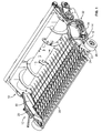
- FIGS 1-3 show a crop gathering device 12 for use with a harvesting header 10.
- Harvesting header 10 may be secured to an agricultural vehicle such as a combine (not shown) as is known in the art and not further discussed.
- a frame 14 carries a conveyor means 22 movable about an endless path to deliver a crop to harvesting header 10.
- conveyor means 22 is a belt, or multiple belts, that extends from one end 18 of frame 14 toward another end 20 of frame 14.
- Conveyor means 22 may be driven about a set of parallel rollers (not shown) by a power source such as a hydraulic motor 34.
- Conveyor means 22 may include a plurality of tines 24 or fork-like components extending outwardly from the conveyor means to assist with collecting crops arranged in a windrow.
- Wheels 26 may be rotatably secured to or near respective ends 18, 20 of frame 14 opposite header 10 to maintain one end of conveyor means 22 near the ground 36 to permit tines 24 of conveyor means 22 to gather or collect crops arranged in the windrow.
- a guide 28 equipped with tines 30 may be positioned over conveyor means 22 to more effectively feed crops from conveyor means 22 to header 10.
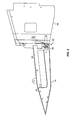
- Frame 14 may be pivotally connected with header 10 about a pivot 38 such as a pin. Without intending to limit the invention, several axes are provided to provide context for the pivotal movement between frame 14 and header 10.
- Header 10 includes a frame 40.
- a corner 42 of frame 40 defines with pivot 38 an axis 44 of header 10.
- axis 44 corresponds to the edge of frame 40 of header 10.
- an axis 46 is defined by pivot 38 and the center 27 of wheel 26.
- An angle 48 is subtended by axes 44 and 46.
- an axis 56 is defined by an upper position along frame 14 and pivot 38 and through center 27 of wheel 26.
- An angle 58 is subtended by axes 44 and 56.
- stabilization system 32 During operation of crop gathering device 12, in which wheel 26 is in contact with ground 36, stabilization system 32 is in a first position, providing a stabilizing torsional force 50 to frame 14 and header 10. That is, stabilization system 32 provides stabilizing torsional force 50 in response to rotational movement about pivot 38 of frame 14 with respect to frame 40 of header 10, as will be discussed in further detail below.
- stabilization system 32 provides a stabilizing torsional force 50 of increased magnitude, as will be further discussed below.
- a resilient device 54 such as a tension spring may be used in combination with stabilization system 32, which may dampen overreactions of relative rotational movement between frame 14 and header 10.
- stabilizing torsional force 50 provided by stabilization system 32 may be either a lifting force or a lowering force, depending upon the settings of stabilization system 32. That is, a lifting force would reduce the amount of force wheels 26 apply to ground 36, while a lowering force would increase the amount of force wheels 26 apply to ground 36.
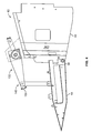
- FIGS 3-4 show alternate embodiments of stabilization system 32, 132.
- stabilization system 32 is positioned along an axis of rotation corresponding with pivot 38.
- stabilization system 132 is at a distance from pivot 38, and includes a linkage 140 that transmits the stabilizing torsional force provided by the stabilization system.
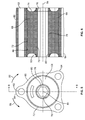
- Figures 5-6 show a side view and a cross section, respectively, of the stabilization system.
- a housing 60 includes a plurality lobes 64 having corresponding apertures 62 formed in the lobes, permitting the housing to be secured to other structure, such as frame 14 or frame 40 ( Figure 2 ) by mechanical fasteners extending through the other structure and apertures 62 (not shown).
- Housing 60 includes an inside surface 66 that may include a tapered surface, such as shown in Figure 6 .
- a member 68 which includes an inside surface 70 and an outside service 72, is composed of a resilient material and is inserted inside of housing 60. In one embodiment, member 68 is composed of a non-metal, such as a rubber material.
- the rubber material has a durometer value of between about 50 and about 60.
- Inside surface 66 of housing 60 is configured to receive outside surface 72 of member 68 and define a substantially non-rotational contact therebetween.
- Inside surface 66 and outside surface 72 should not rotatably move with respect to each other.
- Such non-rotational contact may be established by application of adhesives, interference-fit (due to the periphery of inside surface 66 being larger than the periphery of outside surface 72), mating surface features, such as splines, or the like.
- inside surface 70 of member 68 is configured to receive a sleeve 76 having an outside surface 78 and inside surface 80.
- Housing 60 and sleeve 76 are composed of substantially rigid materials, such as metals.
- inside surface 70 of the member and outside surface 78 of the sleeve define a substantially non-rotational contact therebetween, as discussed above.
- Inside surface 80 of sleeve 76 defines a geometric shape that is configured to receive an object, such as a shaft, in a substantially non-rotational contact.
- inside surface 80 defines a hexagonal profile, although other profiles may be used.
- sleeve 76 may not be used, if inside surface 70 of member 68 defines a hexagonal profile, for example.
- member 68 includes recessed ends 74.
- recessed ends 74 are created during the normal cooling process of member 68, which may be composed of rubber or another suitable resilient material. That is, member 68 is heated to a liquid state and then installed while in the liquid state, such as by pouring, into housing 60 between inside surface 70 and outside surface 72. During cooling, member 68 member 68 bonds to each of inside surface 70 and outside surface 72. In an alternate embodiment, member 68 may be press-fit between inside surface 66 and outside surface 78.
- the member is subjected to a torsional force, which is the basis for the stabilizing torsional force provided by the stabilization system.
- resilient member 68 is considered to have been placed in a substantially non-rotational contact at the inside surface of the member with that of the object being inserted inside the sleeve.
- the sleeve could be associated with either the frame of the header or the frame of the crop gathering device, depending upon the application and or installation of the stabilization system.
- FIG 7 shows an enlarged partial view of the exemplary embodiment of Figure 4 .
- Stabilization system 132 includes components as described in Figures 5-6 (including housing 60, member 68, and sleeve 76), as well as a pair of supports 90 that are secured to header frame 40, a torque arm 92, bushings 104 and a hexagonal shaft 100.
- Fasteners 106 extend through arms 90 and housing 60 so that the housing does not rotate with respect to frame 40.
- Shaft 100 collectively extends through torque arm 92, supports 90, bushings 104, torsion arm 108 along an axis 98, although the shaft may rotate independently of supports 90, permitting relative rotational movement between torsion arm 108, which is part of linkage 140.
- Shaft 100 includes openings 102 formed perpendicular to axis 98 to permit installation of fasteners (not shown) such as cotter pins.
- Stabilization system 132 may be adjustable, i.e., provide an adjustable stabilizing torsional force, such as by adjusting a force 96 that is applied to torque arm 92 through aperture 94 of the torque arm.
- a draw bolt or other suitable fastener (not shown) may be utilized to vary the angle between torque arm 92 and frame 40. That is, adjustment of force 96, such as by a threaded fastener results in rotational movement 110 of torque arm 92 about axis 98. Relative rotational movement 150 of torsion arm 108 about axis 98 with respect to torque arm 92 results in the magnitude of a reactive stabilizing torsional force reacted by the stabilization system.
Landscapes
- Life Sciences & Earth Sciences (AREA)
- Environmental Sciences (AREA)
- Harvesting Machines For Root Crops (AREA)
- Agricultural Machines (AREA)
- Harvesting Machines For Specific Crops (AREA)
- Harvester Elements (AREA)
Abstract
Description
- The present invention relates generally to crop gathering devices. It relates more particularly to crop gathering devices for use with harvesting headers.
- Crop gathering devices for collecting crops arranged in windrows can include a belt positioned along the front of the device as exemplified by
US-B-7,444,798 andEP-A-1 721 512 . The belt is driven to rotate between opposed pairs of roller assemblies to convey the crops into a header that is secured to an agricultural harvester, such as a combine which is directed along the windrow. One or more wheels may be located near the belt opposite the header to maintain a spacing between the belt and the ground that most effectively conveys crops onto the belt. - During operation of the harvester, for reasons including uneven terrain and velocity of the harvester, the spacing between the belt and the ground can deviate from an optimum crop conveying position. In response, tension springs have been positioned between the crop gathering device and the header. While use of tension springs can help reduce such deviations, forces applied by tension springs can vary broadly in response to changes in length of the springs.
- What is needed is a stabilization system that provides a stabilizing force between the crop gathering device and the header over the range of movement between the crop gathering device and the header.
- The present invention relates to a crop harvesting header provided with a crop gathering device having a frame carrying conveyor means movable about an endless path to deliver a crop to the header. The frame has opposed ends and is pivotably connected to the header, each end of the frame being independently movable between a first angle between the frame and the header and a second angle between the frame and the header. The header is also provided with a stabilization system providing a stabilizing force between the frame and the header between the first and second angles. The stabilization system comprises a member having an inside surface connected in substantially non-rotational contact to a first structure of one of the frame or the header, and an outside surface connected in substantially non-rotational contact to a second structure of the other of the frame or the header. The first structure is rotationally movable with respect to the second structure under the angular movement of the frame with respect to the header and the member is configured for providing a stabilizing torsional force between the frame and the header between the first and second angles.
- Hence, in response to rotational movement of the first structure associated with the inside surface with respect to the second structure associated with the outside surface, the member provides a stabilizing torsional force between the frame and the header between the first and second angles.
- The stabilizing force may be a lifting or a lowering force. As an advantageous feature, the position of the first structure and/or of the second structure with respect to the associated frame or header may be adjustble for adjusting the stabilizing torsional force.
- The torsion member preferably comprises a contiguous mass of resilient material, preferably a non-metal. This may be a rubber material. The resilient may have been positioned between the first and second structures in a liquid state. The stabilization member preferably has a closed geometric profile, such as an toroid.
- In a preferred embodiment of the invention, the member is located along an axis of rotation between the frame and the header. The first and/or second structure may also comprise a linkage connected to the associated frame or header. Such linkage may enable a location of the stabilization member, distant from the rotation axis of the frame.
- The inside surface of the member may be connected to a sleeve, extending over an object, e.g. a shaft, that is connected to the frame or the header. This object may be rotatable for adjustment of the stabilizing torsion force. The outside surface of the member may be connected to a housing that is connected to the other of the frame or the header.
- An advantage of the present invention is the application of a stabilizing force with reduced variability, compared with tension springs, between the crop gathering device and the header over the range of movement between the crop gathering device and the header.
- Other features and advantages of the present invention will be apparent from the following more detailed description of the preferred embodiment, taken in conjunction with the accompanying drawings which illustrate, by way of example, the invention.
-
-
Figure 1 is a top perspective view of an embodiment of a crop gathering device and harvesting header according to the present invention. -
Figure 2 is a side view of the crop gathering device ofFigure 1 (the crop conveying belt not shown). -
Figures 3-4 are side views of alternate embodiments of the crop gathering device (components removed for clarity) and harvesting header according to the present invention. -
Figure 5 is a side view of a stabilization system of the present invention. -
Figure 6 is a cross section taken along line 6-6 ofFigure 5 . -
Figure 7 is an enlarged side view of a stabilization system as shown inFigure 3 . -
Figure 8 is a top exploded view of the stabilization system ofFigure 5 . - Wherever possible, the same reference numbers will be used throughout the drawings to refer to the same or like parts.
-
Figures 1-3 show acrop gathering device 12 for use with aharvesting header 10.Harvesting header 10 may be secured to an agricultural vehicle such as a combine (not shown) as is known in the art and not further discussed. Aframe 14 carries a conveyor means 22 movable about an endless path to deliver a crop to harvestingheader 10. In one embodiment, conveyor means 22 is a belt, or multiple belts, that extends from oneend 18 offrame 14 toward anotherend 20 offrame 14. Conveyor means 22 may be driven about a set of parallel rollers (not shown) by a power source such as ahydraulic motor 34. Conveyor means 22 may include a plurality oftines 24 or fork-like components extending outwardly from the conveyor means to assist with collecting crops arranged in a windrow.Wheels 26 may be rotatably secured to or nearrespective ends frame 14opposite header 10 to maintain one end of conveyor means 22 near theground 36 to permittines 24 of conveyor means 22 to gather or collect crops arranged in the windrow. Aguide 28 equipped withtines 30 may be positioned over conveyor means 22 to more effectively feed crops from conveyor means 22 toheader 10. -
Frame 14 may be pivotally connected withheader 10 about apivot 38 such as a pin. Without intending to limit the invention, several axes are provided to provide context for the pivotal movement betweenframe 14 andheader 10.Header 10 includes aframe 40. Acorner 42 offrame 40 defines withpivot 38 anaxis 44 ofheader 10. In an alternate embodiment,axis 44 corresponds to the edge offrame 40 ofheader 10. In one position offrame 14, such as whenwheel 26 is in contact withground 36, anaxis 46 is defined bypivot 38 and thecenter 27 ofwheel 26. Anangle 48 is subtended byaxes frame 14, such as whenwheel 26 is raised above and out of contact withground 36, anaxis 56 is defined by an upper position alongframe 14 andpivot 38 and throughcenter 27 ofwheel 26. Anangle 58 is subtended byaxes - During operation of
crop gathering device 12, in whichwheel 26 is in contact withground 36,stabilization system 32 is in a first position, providing a stabilizingtorsional force 50 toframe 14 andheader 10. That is,stabilization system 32 provides stabilizingtorsional force 50 in response to rotational movement aboutpivot 38 offrame 14 with respect toframe 40 ofheader 10, as will be discussed in further detail below. In addition, during further operation ofcrop gathering device 12, during whichwheel 26 is moved to a position that is above ground 36 (such as by striking an obstacle in the field) resulting incenter 27 ofwheel 26 coinciding with axis 56 (in one instance),stabilization system 32 provides a stabilizingtorsional force 50 of increased magnitude, as will be further discussed below. - Optionally, a
resilient device 54, such as a tension spring may be used in combination withstabilization system 32, which may dampen overreactions of relative rotational movement betweenframe 14 andheader 10. - While an exemplary embodiment as shown in
Figure 2 is representative ofstabilization system 32 providing a stabilizingtorsional force 50 resulting in a lowering force, it is to be understood that stabilizingtorsional force 50 provided bystabilization system 32 may be either a lifting force or a lowering force, depending upon the settings ofstabilization system 32. That is, a lifting force would reduce the amount offorce wheels 26 apply toground 36, while a lowering force would increase the amount offorce wheels 26 apply toground 36. -
Figures 3-4 show alternate embodiments ofstabilization system Figure 3 ,stabilization system 32 is positioned along an axis of rotation corresponding withpivot 38. As further shown inFigure 4 ,stabilization system 132 is at a distance frompivot 38, and includes alinkage 140 that transmits the stabilizing torsional force provided by the stabilization system. -
Figures 5-6 show a side view and a cross section, respectively, of the stabilization system. As shown, ahousing 60 includes a plurality lobes 64 having correspondingapertures 62 formed in the lobes, permitting the housing to be secured to other structure, such asframe 14 or frame 40 (Figure 2 ) by mechanical fasteners extending through the other structure and apertures 62 (not shown).Housing 60 includes aninside surface 66 that may include a tapered surface, such as shown inFigure 6 . Amember 68, which includes aninside surface 70 and anoutside service 72, is composed of a resilient material and is inserted inside ofhousing 60. In one embodiment,member 68 is composed of a non-metal, such as a rubber material. In a further embodiment, the rubber material has a durometer value of between about 50 and about 60. Insidesurface 66 ofhousing 60 is configured to receive outsidesurface 72 ofmember 68 and define a substantially non-rotational contact therebetween. Stated another way, subsequent to insertion ofmember 68 inside ofhousing 60, in response to arotational movement 86 applied in a clockwise direction about anaxis 84 tohousing 60 and an opposedrotational movement 88 applied in a counter clockwise direction aboutaxis 84 tomember 68, insidesurface 66 and outsidesurface 72 should not rotatably move with respect to each other. Such non-rotational contact may be established by application of adhesives, interference-fit (due to the periphery ofinside surface 66 being larger than the periphery of outside surface 72), mating surface features, such as splines, or the like. - As further shown in
Figures 5-6 , insidesurface 70 ofmember 68 is configured to receive asleeve 76 having anoutside surface 78 and insidesurface 80.Housing 60 andsleeve 76 are composed of substantially rigid materials, such as metals. Whenmember 68 andsleeve 76 are assembled together, insidesurface 70 of the member and outsidesurface 78 of the sleeve define a substantially non-rotational contact therebetween, as discussed above. Insidesurface 80 ofsleeve 76 defines a geometric shape that is configured to receive an object, such as a shaft, in a substantially non-rotational contact. As shown inFigure 6 , insidesurface 80 defines a hexagonal profile, although other profiles may be used. In a further embodiment,sleeve 76 may not be used, if inside surface 70 ofmember 68 defines a hexagonal profile, for example. - As shown in
Figure 6 ,member 68 includes recessed ends 74. In one embodiment, recessed ends 74 are created during the normal cooling process ofmember 68, which may be composed of rubber or another suitable resilient material. That is,member 68 is heated to a liquid state and then installed while in the liquid state, such as by pouring, intohousing 60 betweeninside surface 70 and outsidesurface 72. During cooling,member 68member 68 bonds to each ofinside surface 70 and outsidesurface 72. In an alternate embodiment,member 68 may be press-fit betweeninside surface 66 and outsidesurface 78. - In summary, by virtue of the collective substantially non-rotational contacts established between corresponding surfaces of
housing 60,member 68,sleeve 76 and a shaft received by the sleeve, in response to arotational movement 86 aboutaxis 84 applied by ashaft member 68, and a counterrotational movement 88 aboutaxis 84 applied to oppose the rotational movement applied by the shaft, the member is subjected to a torsional force, which is the basis for the stabilizing torsional force provided by the stabilization system. - It is to be understood that irrespective the utilization or inclusion of a sleeve as part of the stabilization system of the present invention,
resilient member 68 is considered to have been placed in a substantially non-rotational contact at the inside surface of the member with that of the object being inserted inside the sleeve. For example, the sleeve could be associated with either the frame of the header or the frame of the crop gathering device, depending upon the application and or installation of the stabilization system. -
Figure 7 shows an enlarged partial view of the exemplary embodiment ofFigure 4 .Stabilization system 132 includes components as described inFigures 5-6 (includinghousing 60,member 68, and sleeve 76), as well as a pair ofsupports 90 that are secured toheader frame 40, atorque arm 92,bushings 104 and ahexagonal shaft 100.Fasteners 106 extend througharms 90 andhousing 60 so that the housing does not rotate with respect to frame 40.Shaft 100 collectively extends throughtorque arm 92, supports 90,bushings 104,torsion arm 108 along anaxis 98, although the shaft may rotate independently ofsupports 90, permitting relative rotational movement betweentorsion arm 108, which is part oflinkage 140.Shaft 100 includesopenings 102 formed perpendicular toaxis 98 to permit installation of fasteners (not shown) such as cotter pins.Stabilization system 132 may be adjustable, i.e., provide an adjustable stabilizing torsional force, such as by adjusting aforce 96 that is applied totorque arm 92 throughaperture 94 of the torque arm. A draw bolt or other suitable fastener (not shown) may be utilized to vary the angle betweentorque arm 92 andframe 40. That is, adjustment offorce 96, such as by a threaded fastener results inrotational movement 110 oftorque arm 92 aboutaxis 98. Relativerotational movement 150 oftorsion arm 108 aboutaxis 98 with respect totorque arm 92 results in the magnitude of a reactive stabilizing torsional force reacted by the stabilization system. - While the invention has been described with reference to a preferred embodiment, it will be understood by those skilled in the art that various changes may be made and equivalents may be substituted for elements thereof without departing from the scope of the invention as defined by the claims. Many modifications may be made to adapt a particular situation or material to the teachings of the invention without departing from this essential scope. Therefore, it is intended that the invention not be limited to the particular embodiment disclosed as the best mode contemplated for carrying out this invention, but that the invention will include all embodiments falling within the scope of the appended claims.
Claims (15)
- A crop harvesting header (10) provided with:a crop gathering device (12) having a frame (14) carrying conveyor means (22) movable about an endless path to deliver a crop to the header (10), the frame having opposed ends (18, 20) and being pivotably connected to the header (10), each end (18/20) of the frame being independently movable between a first angle (48) between the frame (14) and the header (10) and a second angle (58) between the frame and the header; anda stabilization system (32) providing a stabilizing force between the frame (14) and the header (10) between the first and second angles (48, 58),characterized in that:the stabilization system (32) comprises a member (68) having an inside surface (70) connected in substantially non-rotational contact to a first structure of one of the frame (14) or the header (10), and an outside surface (72) connected in substantially non-rotational contact to a second structure of the other of the frame (14) or the header (10),the first structure is rotationally movable with respect to the second structure under the angular movement of the frame (14) with respect to the header (10); andthe member (68) is configured for providing a stabilizing torsional force between the frame (14) and the header (10) between the first and second angles (48, 58).
- A header according to claim 1, wherein the stabilizing torsional force is a lifting force.
- A header according to claim 1, wherein the stabilizing torsional force is a lowering force.
- A header according to any of the preceding claims, wherein the position of the first structure and/or of the first structure is adjustable with respect to the associated frame (14) or header (10) for adjusting the stabilizing torsional force.
- A header according to any of the preceding claims, wherein the member (68) comprises a contiguous mass of resilient material.
- A header according to claim 5, wherein the resilient material is a non-metal.
- A header according to claim 6, wherein the non-metal is a rubber material.
- A header according to any of the claims 5 to 7, wherein the resilient material has been positioned between the first structure and the second structure while the resilient material is in a liquid state.
- A header according to any of the preceding claims, wherein the member (68) defines a closed geometric profile.
- A header according to claim 9, wherein the closed geometric profile defines a toroid.
- A header according to any of the preceding claims, wherein the member (68) is located along an axis of rotation (38) between the frame (14) and the header (10).
- A header according to any of the preceding claims, wherein the first and/or second structure comprises a linkage (140) connected to the associated frame (14) or header (10).
- A header according to any of the preceding claims, wherein the first structure connected to the inside surface (70) of the member (68) comprises a sleeve (76) extending over an object, in particular a shaft, that is connected to one of the frame (14) or the header (10).
- A header according to claim 13, wherein the object is mounted for rotation about an axis (98) to the one of the frame (14) or the header (10) for adjustment of the stabilizing torsional force.
- A header according to any of the preceding claims, wherein the second structure connected to the outside surface (72) of the member (68) comprises a housing (60) that is connected to the other of the frame (14) or the header (10).
Applications Claiming Priority (1)
| Application Number | Priority Date | Filing Date | Title |
|---|---|---|---|
| US12/699,342 US7975460B1 (en) | 2010-02-03 | 2010-02-03 | Stabilization system for a crop harvesting header |
Publications (3)
| Publication Number | Publication Date |
|---|---|
| EP2359675A2 true EP2359675A2 (en) | 2011-08-24 |
| EP2359675A3 EP2359675A3 (en) | 2012-08-22 |
| EP2359675B1 EP2359675B1 (en) | 2016-11-30 |
Family
ID=44245417
Family Applications (1)
| Application Number | Title | Priority Date | Filing Date |
|---|---|---|---|
| EP11152844.4A Active EP2359675B1 (en) | 2010-02-03 | 2011-02-01 | Stabilization system for a crop harvesting header |
Country Status (3)
| Country | Link |
|---|---|
| US (1) | US7975460B1 (en) |
| EP (1) | EP2359675B1 (en) |
| RU (1) | RU2554440C2 (en) |
Citations (2)
| Publication number | Priority date | Publication date | Assignee | Title |
|---|---|---|---|---|
| EP1721512A1 (en) | 2005-05-11 | 2006-11-15 | Deere & Company | Cutting device with a belt conveyor assembly |
| US7444798B2 (en) | 2006-07-26 | 2008-11-04 | Macdon Industries Ltd. | Crop feed arrangement for the header of a combine harvester |
Family Cites Families (25)
| Publication number | Priority date | Publication date | Assignee | Title |
|---|---|---|---|---|
| US3771302A (en) * | 1972-06-08 | 1973-11-13 | Deere & Co | Gauge wheel mounting for a harvester |
| US3783594A (en) * | 1972-09-18 | 1974-01-08 | Int Harvester Co | Harvester platform suspension and linkage system |
| US4081946A (en) * | 1976-12-01 | 1978-04-04 | Sperry Rand Corporation | Header suspension and lift means |
| US4137696A (en) * | 1977-01-07 | 1979-02-06 | Sperry Rand Corporation | Header suspension and lift means |
| US4127981A (en) * | 1977-01-17 | 1978-12-05 | Sperry Rand Corporation | Drive means for a crop harvesting machine |
| US4211057A (en) * | 1978-03-20 | 1980-07-08 | Massey-Ferguson Industries Limited | Combine harvester automatic table height control |
| US4174602A (en) * | 1978-03-31 | 1979-11-20 | Sperry Rand Corporation | Header suspension and stabilization means |
| US4318631A (en) * | 1980-01-21 | 1982-03-09 | Vickers Richard R | Texturing broom apparatus for roadway pavements |
| US4519188A (en) * | 1984-03-02 | 1985-05-28 | Sperry Corporation | Linkage for equalizing conditioning roll pressure |
| US4573308A (en) * | 1984-04-02 | 1986-03-04 | Deere & Company | Harvesting platform with a floating cutterbar |
| US4722173A (en) * | 1984-06-11 | 1988-02-02 | J. I. Case Company | Cotton harvester harvesting unit support system |
| FR2571586B1 (en) * | 1984-10-16 | 1994-12-09 | Kuhn Sa | MOWER, SHOCK ABSORBER AND SHOCK ABSORBER DEVICE EQUIPPED WITH THIS MOWER |
| SU1306510A1 (en) * | 1984-12-11 | 1987-04-30 | Тульский Проектно-Конструкторский Технологический Институт Комбайностроения | Feeler mechanism for windrower cutting apparatus of grain combine harvester |
| US4961303A (en) * | 1989-07-10 | 1990-10-09 | Ford New Holland, Inc. | Apparatus for opening conditioning rolls |
| US5115628A (en) * | 1990-12-12 | 1992-05-26 | J. I. Case Company | Height control system for a cotton harvester |
| FR2696898B1 (en) * | 1992-10-16 | 1994-12-09 | Kuhn Sa | Mower with improved drive of the processing rollers. |
| CA2139443C (en) * | 1995-01-03 | 2002-11-12 | Gregory J. Honey | Linkage device for mounting swather header |
| US5960620A (en) * | 1998-02-11 | 1999-10-05 | Ogden Metalworks, Inc. | Rake arm assembly |
| US6530197B1 (en) * | 2000-05-16 | 2003-03-11 | Deere & Company | Ground contact height sensor |
| DE10221735A1 (en) * | 2002-05-16 | 2003-12-24 | Deere & Co | Good take-up device and height guiding device |
| US20040065069A1 (en) * | 2002-10-02 | 2004-04-08 | Dunn James Thomas | Crop harvesting machine with recoil action on impact with an obstacle |
| US20060053761A1 (en) * | 2004-09-10 | 2006-03-16 | Clark Equipment Company | Floating attachment linkage |
| US7617662B2 (en) * | 2005-06-14 | 2009-11-17 | Deere & Company | Integrated crop baffle and hold-down assembly used with baler pick-up and suspension for same |
| US7555885B2 (en) * | 2007-01-05 | 2009-07-07 | Agco Corporation | Crop pickup with torsion bar flotation |
| US7610739B2 (en) * | 2007-10-18 | 2009-11-03 | Beeline Mowers And Equipment, Llc | Riding mower |
-
2010
- 2010-02-03 US US12/699,342 patent/US7975460B1/en active Active
-
2011
- 2011-02-01 EP EP11152844.4A patent/EP2359675B1/en active Active
- 2011-02-02 RU RU2011103751/13A patent/RU2554440C2/en active
Patent Citations (2)
| Publication number | Priority date | Publication date | Assignee | Title |
|---|---|---|---|---|
| EP1721512A1 (en) | 2005-05-11 | 2006-11-15 | Deere & Company | Cutting device with a belt conveyor assembly |
| US7444798B2 (en) | 2006-07-26 | 2008-11-04 | Macdon Industries Ltd. | Crop feed arrangement for the header of a combine harvester |
Also Published As
| Publication number | Publication date |
|---|---|
| EP2359675A3 (en) | 2012-08-22 |
| US20110185694A1 (en) | 2011-08-04 |
| US7975460B1 (en) | 2011-07-12 |
| EP2359675B1 (en) | 2016-11-30 |
| RU2554440C2 (en) | 2015-06-27 |
| RU2011103751A (en) | 2012-08-10 |
Similar Documents
| Publication | Publication Date | Title |
|---|---|---|
| EP2702851B1 (en) | System for cutterbar support having torsion device with elastic material and load limiting apparatus | |
| EP2552186B1 (en) | Cutterbar support for a crop harvesting header | |
| US8266881B2 (en) | Flexible motor support system for a crop gathering device having a harvesting header | |
| US8051633B2 (en) | Cutterbar adjustment support for a crop harvesting header | |
| EP2480064B1 (en) | Crop gathering device for harvesting header | |
| US7188461B2 (en) | Conditioning roller drive | |
| US7950212B1 (en) | Cutterbar support for a crop harvesting header | |
| EP2525642B1 (en) | Replaceable guide assembly tines for an agricultural harvester | |
| EP3119183B1 (en) | Harvester | |
| EP2359675B1 (en) | Stabilization system for a crop harvesting header | |
| CN111432627A (en) | Roller and roller group for harvesting machine, harvesting machine and harvesting table | |
| US8122694B2 (en) | Suspension system for a crop harvesting header | |
| US11617296B2 (en) | Agricultural machine equipped with a distribution tie-rod | |
| KR101623846B1 (en) | Multi-purpose mower for agriculture | |
| EP1653112B1 (en) | Pick-up for collecting agricultural produce on the ground | |
| US11470762B2 (en) | Agricultural machine and folding method for an agricultural machine | |
| KR200312844Y1 (en) | Structure for Delivering Force of Soil Crops Harvester | |
| CN101642017B (en) | Crop holding adjuster | |
| RU2309576C1 (en) | Hanged finger wheel fitting for tedder rake of swath maker | |
| KR200200096Y1 (en) | The crops gathering machine |
Legal Events
| Date | Code | Title | Description |
|---|---|---|---|
| PUAI | Public reference made under article 153(3) epc to a published international application that has entered the european phase |
Free format text: ORIGINAL CODE: 0009012 |
|
| AK | Designated contracting states |
Kind code of ref document: A2 Designated state(s): AL AT BE BG CH CY CZ DE DK EE ES FI FR GB GR HR HU IE IS IT LI LT LU LV MC MK MT NL NO PL PT RO RS SE SI SK SM TR |
|
| AX | Request for extension of the european patent |
Extension state: BA ME |
|
| PUAL | Search report despatched |
Free format text: ORIGINAL CODE: 0009013 |
|
| AK | Designated contracting states |
Kind code of ref document: A3 Designated state(s): AL AT BE BG CH CY CZ DE DK EE ES FI FR GB GR HR HU IE IS IT LI LT LU LV MC MK MT NL NO PL PT RO RS SE SI SK SM TR |
|
| AX | Request for extension of the european patent |
Extension state: BA ME |
|
| RIC1 | Information provided on ipc code assigned before grant |
Ipc: A01D 41/14 20060101AFI20120718BHEP |
|
| 17P | Request for examination filed |
Effective date: 20130222 |
|
| RAP1 | Party data changed (applicant data changed or rights of an application transferred) |
Owner name: CNH INDUSTRIAL BELGIUM NV |
|
| GRAP | Despatch of communication of intention to grant a patent |
Free format text: ORIGINAL CODE: EPIDOSNIGR1 |
|
| INTG | Intention to grant announced |
Effective date: 20160704 |
|
| GRAS | Grant fee paid |
Free format text: ORIGINAL CODE: EPIDOSNIGR3 |
|
| GRAA | (expected) grant |
Free format text: ORIGINAL CODE: 0009210 |
|
| AK | Designated contracting states |
Kind code of ref document: B1 Designated state(s): AL AT BE BG CH CY CZ DE DK EE ES FI FR GB GR HR HU IE IS IT LI LT LU LV MC MK MT NL NO PL PT RO RS SE SI SK SM TR |
|
| REG | Reference to a national code |
Ref country code: CH Ref legal event code: EP Ref country code: GB Ref legal event code: FG4D |
|
| REG | Reference to a national code |
Ref country code: AT Ref legal event code: REF Ref document number: 848900 Country of ref document: AT Kind code of ref document: T Effective date: 20161215 |
|
| REG | Reference to a national code |
Ref country code: IE Ref legal event code: FG4D |
|
| REG | Reference to a national code |
Ref country code: FR Ref legal event code: PLFP Year of fee payment: 7 |
|
| REG | Reference to a national code |
Ref country code: DE Ref legal event code: R096 Ref document number: 602011032840 Country of ref document: DE |
|
| PG25 | Lapsed in a contracting state [announced via postgrant information from national office to epo] |
Ref country code: LV Free format text: LAPSE BECAUSE OF FAILURE TO SUBMIT A TRANSLATION OF THE DESCRIPTION OR TO PAY THE FEE WITHIN THE PRESCRIBED TIME-LIMIT Effective date: 20161130 |
|
| REG | Reference to a national code |
Ref country code: LT Ref legal event code: MG4D |
|
| REG | Reference to a national code |
Ref country code: NL Ref legal event code: MP Effective date: 20161130 |
|
| REG | Reference to a national code |
Ref country code: AT Ref legal event code: MK05 Ref document number: 848900 Country of ref document: AT Kind code of ref document: T Effective date: 20161130 |
|
| PG25 | Lapsed in a contracting state [announced via postgrant information from national office to epo] |
Ref country code: SE Free format text: LAPSE BECAUSE OF FAILURE TO SUBMIT A TRANSLATION OF THE DESCRIPTION OR TO PAY THE FEE WITHIN THE PRESCRIBED TIME-LIMIT Effective date: 20161130 Ref country code: LT Free format text: LAPSE BECAUSE OF FAILURE TO SUBMIT A TRANSLATION OF THE DESCRIPTION OR TO PAY THE FEE WITHIN THE PRESCRIBED TIME-LIMIT Effective date: 20161130 Ref country code: NO Free format text: LAPSE BECAUSE OF FAILURE TO SUBMIT A TRANSLATION OF THE DESCRIPTION OR TO PAY THE FEE WITHIN THE PRESCRIBED TIME-LIMIT Effective date: 20170228 Ref country code: GR Free format text: LAPSE BECAUSE OF FAILURE TO SUBMIT A TRANSLATION OF THE DESCRIPTION OR TO PAY THE FEE WITHIN THE PRESCRIBED TIME-LIMIT Effective date: 20170301 |
|
| PG25 | Lapsed in a contracting state [announced via postgrant information from national office to epo] |
Ref country code: RS Free format text: LAPSE BECAUSE OF FAILURE TO SUBMIT A TRANSLATION OF THE DESCRIPTION OR TO PAY THE FEE WITHIN THE PRESCRIBED TIME-LIMIT Effective date: 20161130 Ref country code: AT Free format text: LAPSE BECAUSE OF FAILURE TO SUBMIT A TRANSLATION OF THE DESCRIPTION OR TO PAY THE FEE WITHIN THE PRESCRIBED TIME-LIMIT Effective date: 20161130 Ref country code: ES Free format text: LAPSE BECAUSE OF FAILURE TO SUBMIT A TRANSLATION OF THE DESCRIPTION OR TO PAY THE FEE WITHIN THE PRESCRIBED TIME-LIMIT Effective date: 20161130 Ref country code: FI Free format text: LAPSE BECAUSE OF FAILURE TO SUBMIT A TRANSLATION OF THE DESCRIPTION OR TO PAY THE FEE WITHIN THE PRESCRIBED TIME-LIMIT Effective date: 20161130 Ref country code: BE Free format text: LAPSE BECAUSE OF NON-PAYMENT OF DUE FEES Effective date: 20170228 Ref country code: PL Free format text: LAPSE BECAUSE OF FAILURE TO SUBMIT A TRANSLATION OF THE DESCRIPTION OR TO PAY THE FEE WITHIN THE PRESCRIBED TIME-LIMIT Effective date: 20161130 Ref country code: HR Free format text: LAPSE BECAUSE OF FAILURE TO SUBMIT A TRANSLATION OF THE DESCRIPTION OR TO PAY THE FEE WITHIN THE PRESCRIBED TIME-LIMIT Effective date: 20161130 Ref country code: PT Free format text: LAPSE BECAUSE OF FAILURE TO SUBMIT A TRANSLATION OF THE DESCRIPTION OR TO PAY THE FEE WITHIN THE PRESCRIBED TIME-LIMIT Effective date: 20170330 |
|
| PG25 | Lapsed in a contracting state [announced via postgrant information from national office to epo] |
Ref country code: NL Free format text: LAPSE BECAUSE OF FAILURE TO SUBMIT A TRANSLATION OF THE DESCRIPTION OR TO PAY THE FEE WITHIN THE PRESCRIBED TIME-LIMIT Effective date: 20161130 |
|
| PG25 | Lapsed in a contracting state [announced via postgrant information from national office to epo] |
Ref country code: SK Free format text: LAPSE BECAUSE OF FAILURE TO SUBMIT A TRANSLATION OF THE DESCRIPTION OR TO PAY THE FEE WITHIN THE PRESCRIBED TIME-LIMIT Effective date: 20161130 Ref country code: CZ Free format text: LAPSE BECAUSE OF FAILURE TO SUBMIT A TRANSLATION OF THE DESCRIPTION OR TO PAY THE FEE WITHIN THE PRESCRIBED TIME-LIMIT Effective date: 20161130 Ref country code: RO Free format text: LAPSE BECAUSE OF FAILURE TO SUBMIT A TRANSLATION OF THE DESCRIPTION OR TO PAY THE FEE WITHIN THE PRESCRIBED TIME-LIMIT Effective date: 20161130 Ref country code: DK Free format text: LAPSE BECAUSE OF FAILURE TO SUBMIT A TRANSLATION OF THE DESCRIPTION OR TO PAY THE FEE WITHIN THE PRESCRIBED TIME-LIMIT Effective date: 20161130 Ref country code: EE Free format text: LAPSE BECAUSE OF FAILURE TO SUBMIT A TRANSLATION OF THE DESCRIPTION OR TO PAY THE FEE WITHIN THE PRESCRIBED TIME-LIMIT Effective date: 20161130 |
|
| PG25 | Lapsed in a contracting state [announced via postgrant information from national office to epo] |
Ref country code: IT Free format text: LAPSE BECAUSE OF FAILURE TO SUBMIT A TRANSLATION OF THE DESCRIPTION OR TO PAY THE FEE WITHIN THE PRESCRIBED TIME-LIMIT Effective date: 20161130 Ref country code: BG Free format text: LAPSE BECAUSE OF FAILURE TO SUBMIT A TRANSLATION OF THE DESCRIPTION OR TO PAY THE FEE WITHIN THE PRESCRIBED TIME-LIMIT Effective date: 20170228 Ref country code: BE Free format text: LAPSE BECAUSE OF FAILURE TO SUBMIT A TRANSLATION OF THE DESCRIPTION OR TO PAY THE FEE WITHIN THE PRESCRIBED TIME-LIMIT Effective date: 20161130 Ref country code: SM Free format text: LAPSE BECAUSE OF FAILURE TO SUBMIT A TRANSLATION OF THE DESCRIPTION OR TO PAY THE FEE WITHIN THE PRESCRIBED TIME-LIMIT Effective date: 20161130 |
|
| REG | Reference to a national code |
Ref country code: DE Ref legal event code: R097 Ref document number: 602011032840 Country of ref document: DE |
|
| PG25 | Lapsed in a contracting state [announced via postgrant information from national office to epo] |
Ref country code: MC Free format text: LAPSE BECAUSE OF FAILURE TO SUBMIT A TRANSLATION OF THE DESCRIPTION OR TO PAY THE FEE WITHIN THE PRESCRIBED TIME-LIMIT Effective date: 20161130 |
|
| REG | Reference to a national code |
Ref country code: CH Ref legal event code: PL |
|
| PLBE | No opposition filed within time limit |
Free format text: ORIGINAL CODE: 0009261 |
|
| STAA | Information on the status of an ep patent application or granted ep patent |
Free format text: STATUS: NO OPPOSITION FILED WITHIN TIME LIMIT |
|
| PG25 | Lapsed in a contracting state [announced via postgrant information from national office to epo] |
Ref country code: CH Free format text: LAPSE BECAUSE OF NON-PAYMENT OF DUE FEES Effective date: 20170228 Ref country code: LI Free format text: LAPSE BECAUSE OF NON-PAYMENT OF DUE FEES Effective date: 20170228 |
|
| 26N | No opposition filed |
Effective date: 20170831 |
|
| REG | Reference to a national code |
Ref country code: IE Ref legal event code: MM4A |
|
| PG25 | Lapsed in a contracting state [announced via postgrant information from national office to epo] |
Ref country code: SI Free format text: LAPSE BECAUSE OF FAILURE TO SUBMIT A TRANSLATION OF THE DESCRIPTION OR TO PAY THE FEE WITHIN THE PRESCRIBED TIME-LIMIT Effective date: 20161130 |
|
| PG25 | Lapsed in a contracting state [announced via postgrant information from national office to epo] |
Ref country code: LU Free format text: LAPSE BECAUSE OF NON-PAYMENT OF DUE FEES Effective date: 20170201 |
|
| REG | Reference to a national code |
Ref country code: FR Ref legal event code: PLFP Year of fee payment: 8 |
|
| PG25 | Lapsed in a contracting state [announced via postgrant information from national office to epo] |
Ref country code: IE Free format text: LAPSE BECAUSE OF NON-PAYMENT OF DUE FEES Effective date: 20170201 |
|
| PG25 | Lapsed in a contracting state [announced via postgrant information from national office to epo] |
Ref country code: MT Free format text: LAPSE BECAUSE OF NON-PAYMENT OF DUE FEES Effective date: 20170201 |
|
| PG25 | Lapsed in a contracting state [announced via postgrant information from national office to epo] |
Ref country code: HU Free format text: LAPSE BECAUSE OF FAILURE TO SUBMIT A TRANSLATION OF THE DESCRIPTION OR TO PAY THE FEE WITHIN THE PRESCRIBED TIME-LIMIT; INVALID AB INITIO Effective date: 20110201 |
|
| PG25 | Lapsed in a contracting state [announced via postgrant information from national office to epo] |
Ref country code: CY Free format text: LAPSE BECAUSE OF NON-PAYMENT OF DUE FEES Effective date: 20161130 |
|
| PG25 | Lapsed in a contracting state [announced via postgrant information from national office to epo] |
Ref country code: MK Free format text: LAPSE BECAUSE OF FAILURE TO SUBMIT A TRANSLATION OF THE DESCRIPTION OR TO PAY THE FEE WITHIN THE PRESCRIBED TIME-LIMIT Effective date: 20161130 |
|
| PG25 | Lapsed in a contracting state [announced via postgrant information from national office to epo] |
Ref country code: TR Free format text: LAPSE BECAUSE OF FAILURE TO SUBMIT A TRANSLATION OF THE DESCRIPTION OR TO PAY THE FEE WITHIN THE PRESCRIBED TIME-LIMIT Effective date: 20161130 |
|
| REG | Reference to a national code |
Ref country code: DE Ref legal event code: R082 Ref document number: 602011032840 Country of ref document: DE Representative=s name: MEISSNER BOLTE PATENTANWAELTE RECHTSANWAELTE P, DE |
|
| PG25 | Lapsed in a contracting state [announced via postgrant information from national office to epo] |
Ref country code: AL Free format text: LAPSE BECAUSE OF FAILURE TO SUBMIT A TRANSLATION OF THE DESCRIPTION OR TO PAY THE FEE WITHIN THE PRESCRIBED TIME-LIMIT Effective date: 20161130 Ref country code: IS Free format text: LAPSE BECAUSE OF FAILURE TO SUBMIT A TRANSLATION OF THE DESCRIPTION OR TO PAY THE FEE WITHIN THE PRESCRIBED TIME-LIMIT Effective date: 20170330 |
|
| PGFP | Annual fee paid to national office [announced via postgrant information from national office to epo] |
Ref country code: GB Payment date: 20260223 Year of fee payment: 16 |
|
| PGFP | Annual fee paid to national office [announced via postgrant information from national office to epo] |
Ref country code: DE Payment date: 20260220 Year of fee payment: 16 |
|
| PGFP | Annual fee paid to national office [announced via postgrant information from national office to epo] |
Ref country code: FR Payment date: 20260227 Year of fee payment: 16 |