EP2359045B1 - Ensemble d'étanchéité et jonction tubulaire correspondante - Google Patents
Ensemble d'étanchéité et jonction tubulaire correspondante Download PDFInfo
- Publication number
- EP2359045B1 EP2359045B1 EP09821423.2A EP09821423A EP2359045B1 EP 2359045 B1 EP2359045 B1 EP 2359045B1 EP 09821423 A EP09821423 A EP 09821423A EP 2359045 B1 EP2359045 B1 EP 2359045B1
- Authority
- EP
- European Patent Office
- Prior art keywords
- flexion
- extrusion
- set according
- circumferential
- recess
- Prior art date
- Legal status (The legal status is an assumption and is not a legal conclusion. Google has not performed a legal analysis and makes no representation as to the accuracy of the status listed.)
- Not-in-force
Links
- 238000001125 extrusion Methods 0.000 claims description 97
- 238000007789 sealing Methods 0.000 claims description 26
- 125000006850 spacer group Chemical group 0.000 claims description 4
- 238000004873 anchoring Methods 0.000 claims description 3
- 238000005452 bending Methods 0.000 description 20
- 238000004519 manufacturing process Methods 0.000 description 5
- 230000000712 assembly Effects 0.000 description 3
- 238000000429 assembly Methods 0.000 description 3
- 239000000463 material Substances 0.000 description 3
- 230000000694 effects Effects 0.000 description 2
- 229920001971 elastomer Polymers 0.000 description 2
- -1 polyethylene Polymers 0.000 description 2
- 229910001018 Cast iron Inorganic materials 0.000 description 1
- 239000004952 Polyamide Substances 0.000 description 1
- 239000004698 Polyethylene Substances 0.000 description 1
- 239000004743 Polypropylene Substances 0.000 description 1
- 241001080024 Telles Species 0.000 description 1
- 230000001154 acute effect Effects 0.000 description 1
- 238000004026 adhesive bonding Methods 0.000 description 1
- 239000011230 binding agent Substances 0.000 description 1
- 230000000295 complement effect Effects 0.000 description 1
- 230000001419 dependent effect Effects 0.000 description 1
- 238000006073 displacement reaction Methods 0.000 description 1
- 239000003651 drinking water Substances 0.000 description 1
- 235000020188 drinking water Nutrition 0.000 description 1
- 239000000806 elastomer Substances 0.000 description 1
- 230000037431 insertion Effects 0.000 description 1
- 238000003780 insertion Methods 0.000 description 1
- 239000002184 metal Substances 0.000 description 1
- 229910052751 metal Inorganic materials 0.000 description 1
- 239000004033 plastic Substances 0.000 description 1
- 229920003023 plastic Polymers 0.000 description 1
- 229920002647 polyamide Polymers 0.000 description 1
- 229920000573 polyethylene Polymers 0.000 description 1
- 229920001155 polypropylene Polymers 0.000 description 1
- 239000011241 protective layer Substances 0.000 description 1
- 239000002351 wastewater Substances 0.000 description 1
Images





Classifications
-
- F—MECHANICAL ENGINEERING; LIGHTING; HEATING; WEAPONS; BLASTING
- F16—ENGINEERING ELEMENTS AND UNITS; GENERAL MEASURES FOR PRODUCING AND MAINTAINING EFFECTIVE FUNCTIONING OF MACHINES OR INSTALLATIONS; THERMAL INSULATION IN GENERAL
- F16L—PIPES; JOINTS OR FITTINGS FOR PIPES; SUPPORTS FOR PIPES, CABLES OR PROTECTIVE TUBING; MEANS FOR THERMAL INSULATION IN GENERAL
- F16L21/00—Joints with sleeve or socket
- F16L21/02—Joints with sleeve or socket with elastic sealing rings between pipe and sleeve or between pipe and socket, e.g. with rolling or other prefabricated profiled rings
- F16L21/03—Joints with sleeve or socket with elastic sealing rings between pipe and sleeve or between pipe and socket, e.g. with rolling or other prefabricated profiled rings placed in the socket before connection
-
- F—MECHANICAL ENGINEERING; LIGHTING; HEATING; WEAPONS; BLASTING
- F16—ENGINEERING ELEMENTS AND UNITS; GENERAL MEASURES FOR PRODUCING AND MAINTAINING EFFECTIVE FUNCTIONING OF MACHINES OR INSTALLATIONS; THERMAL INSULATION IN GENERAL
- F16L—PIPES; JOINTS OR FITTINGS FOR PIPES; SUPPORTS FOR PIPES, CABLES OR PROTECTIVE TUBING; MEANS FOR THERMAL INSULATION IN GENERAL
- F16L37/00—Couplings of the quick-acting type
- F16L37/08—Couplings of the quick-acting type in which the connection between abutting or axially overlapping ends is maintained by locking members
- F16L37/084—Couplings of the quick-acting type in which the connection between abutting or axially overlapping ends is maintained by locking members combined with automatic locking
- F16L37/0845—Couplings of the quick-acting type in which the connection between abutting or axially overlapping ends is maintained by locking members combined with automatic locking by means of retaining members associated with the packing member
Definitions
- the present invention relates to a sealing assembly for a tubular joint according to the preamble of claim 1.
- the known assemblies comprise anti-extrusion elements opposing the extrusion of the seal through the gap present between the interlocking end and the spigot. These elements have a radial rigidity which is substantially identical over their entire circumferential extent. However, because of this uniform rigidity, the known sealing assemblies do not adapt well to the variations in play between the spigot and the socket end resulting from manufacturing tolerances. In addition, they create a risk of sealing failure during an angular deflection between the spigot end and the interlocking end.
- the invention aims to overcome this disadvantage and to propose a tubular junction which improves the sealing, and this with economic means.
- the subject of the invention is a sealing assembly, of the type indicated, characterized by the characterizing part of claim 1.
- the assembly comprises one or more of the features of the dependent claims.
- the invention further relates to a tubular junction of the type comprising an interlocking end of a first pipe element, the interlocking end extending along a central axis, being provided with an inner groove and one end. in which is inserted a spigot of a second pipe element, the inner groove forming a groove wall which is inclined relative to the central axis and which tapers towards the free end of the interlocking end, characterized in that it includes a sealing assembly as defined above.
- the Figure 1 shows a tubular junction according to the invention, designated by the general reference 2.
- the tubular junction 2 comprises a first pipe element provided with an interlocking end 4, a second pipe element provided with a spigot end 6, and a sealing assembly 7.
- This sealing assembly 7 comprises a gasket sealing 8 and anti-extrusion elements 10.
- the tubular junction 2 defines a central axis XX coinciding with the central axis of the interlocking end and the seal 8.
- axially axially
- radially radially
- circumferentially axially
- the interlocking end 4 and the spigot 6 are made of cast iron, for example.
- these pipe elements may be coated with a protective layer not shown.
- the socket end 4 comprises a fastening flange 14 for assembly with a pipe element (not shown) provided with a corresponding flange, and a free end 16, turned towards the spigot end 6 in the non-state. assembled.
- the interlocking end 4 further comprises an inner annular groove 18 (see FIG. Figure 2 ).
- the inner groove 18 forms a groove wall 20 inclined with respect to the central axis XX.
- the wall 20 has a frustoconical shape and narrows towards the free end 16 of the interlocking end. It forms an angle ⁇ with the central axis XX.
- the seal 8 provided with the anti-extrusion elements 10, is inserted into the internal groove 18 of the interlocking end.
- the seal 8 is arranged axially on the side facing the fastening flange 14, while the anti-extrusion elements 10, fixed to the seal 8, are arranged axially on the free end 16 side.
- the socket end 4 has a radially inner surface 21 which extends between the free end 16 and the groove wall 20.
- This surface 21 is substantially cylindrical and is defined by a radius R about the axis XX.
- the spigot end 6 has a radially outer surface 22 cylindrical and defined by a radius r about the axis XX.
- the radii R and r are within a range of manufacturing tolerances.
- the game between the spigot and the spigot is an average game that is located between the maximum game and the minimum game (see Figure 2 ).
- the seal 8 is for example made of rubber. It comprises an annular base body 24 and an annular sealing lip 26.
- the cross section of the anti-extrusion element 10 is substantially triangular.
- the anti-extrusion element 10 thus forms a frustoconical application face 28 having a component directed radially outwardly, a radially inner face 30 and a connecting face 32 which is adjacent to the seal 8 and which ensures the connection of the anti-extrusion element 10 with the seal 8.
- the connecting face 32 extends in the unstressed state of the seal 8 radially relative to the central axis XX.
- the application face 28 is inclined at an angle ⁇ with respect to the axis XX, which angle is substantially identical to the angle of inclination ⁇ of the groove wall 20.
- the application face 28 is therefore applies flat on the wall 20.
- the application face 28 and the connecting face 32 form at their junction, in radial section, a point of tilting 34 for tilting the anti-extrusion element 10 around the wall 20.
- the anti-extrusion elements 10 have an arcuate shape around the central axis X-X. Thus, the anti-extrusion elements 10 prevent the elastomer of the seal 8 from being extruded out through the annular space defined by the outer surface 22 of the spigot end 6 and the inner surface 21 of the spigot end. interlocking 4 during the pressurization of the pipe elements.
- the anti-extrusion elements 10 are preferably made of a harder plastic than the gasket material, such as polyamide, polyethylene or polypropylene.
- the anti-extrusion elements 10 are attached to the seal 8 by any suitable means. They can in particular be fixed by gluing, overmoulding, snapping, screwing or riveting. To this end, the anti-extrusion elements comprise anchor pins 40, which project on the connecting face 32. Each pin 40 is fixed to the seal 8 by overmolding.
- the connecting face 32 is freely arranged on the seal 8.
- the anti-extrusion element 10 is devoid of any locking element adapted to lock the spigot relative to the interlocking end.
- each anti-extrusion element 10 comprises a so-called rigid circumferential domain 50 and two so-called flexible hoop domains 52.
- the rigid domain 50 extends for example over more than 50% of the circumferential extent of the anti-extrusion element 10. In any case, the rigid domain 50 extends uninterruptedly over a circumferential range which is greater than a circumferential range of one of the flexible domains 52.
- the rigid domain 50 carries at least part of the anchoring studs 40, which facilitates the mounting of the anti-extrusion element 10 in the seal 8.
- Each flexible domain 52 forms a circumferential end of the anti-extrusion element 10, while the rigid domain 50 forms a central circumferential portion of this element.
- the rigid domain 50 has a first stiffness in radial bending and each flexible domain 52 has a second rigidity in radial bending, which is less than the first rigidity in radial bending.
- each flexible domain 52 has empty radial bending slots 54.
- Each bending slot 54 is axially and radially open.
- each bending slot 54 is axially through.
- Each bending slot 54 also forms a radial bottom.
- Each bending slot 54 extends over a flexible circumferential zone 56 and delimits a rigid circumferential zone 58.
- each flexible circumferential zone 56 is smaller than the circumferential extent of the rigid domain 50.
- the circumferential extent of each rigid circumferential zone 58 is smaller than the circumferential extent of the rigid domain 50.
- each circumferential zone rigid 58 has a cross section which is identical to the cross section of the rigid domain 50.
- each flexible circumferential zone is less than 50% of the radial flexural rigidity of each circumferentially rigid zone and / or of the rigid domain 50, in particular less than 40%, 30%, 20% or 10% of the radial stiffness stiffness of each circumferentially rigid zone and / or the rigid domain 50. Also, the radial flexural stiffness of each circumferentially flexible zone 56 is however greater than 5% of the radial flexural stiffness of each circumferentially rigid zone 58 and or the rigid domain 50.
- the bending slots 54 of each flexible domain 52 form a circumferential group 60 with bending slots 54.
- the circumferential distance C1 between two adjacent bending slots 54 of the same group 60 is smaller than the circumferential distance C2 between a bending slot 54. not belonging to the group and the nearest bending slot 54 of the same group 60.
- each flexible circumferential zone 56 are disposed two radially opposed flexion slots 54 which form a core 64.
- the web 64 has a cross section narrowing towards the axial end facing the free end 16 of the interlocking end in the assembled state.
- the cross section of the core 64 is approximately triangular in shape.
- the adjacent flexion slots 54 of the same group 60 have radial depths P1, P2 different from each other. More particularly, the bending slot 54 closer to the circumferential end has a depth P1 greater than the depth P2 of the bending slot 54 closer to the central circumferential portion of the anti-extrusion element 10.
- the flexibility radial of the flexible domain 52 varies over its circumferential extent. Also, the radial flexibility of each flexible domain 52 increases from the central circumferential side to the circumferential end.
- the anti-extrusion elements 10 are separated from each other by a circumferential spacer 66 integrally formed with the gasket 8, this spacer 66 having a circumferential dimension smaller than the circumferential dimension of the anti-extrusion elements 10 so as not to favor the extrusion of the material constituting the seal under the effect of the internal pressure.
- These spacers 66 improve the flexibility of the seal 8 and thus facilitate its deformation for insertion into the interlocking end.
- the assembly of the tubular junction according to the invention is carried out as described below.
- the anti-extrusion elements 10 are fixed on the seal 8.
- the assembly 7 comprising the seal 8 and the anti-extrusion elements 10 can be handled in one piece.
- the seal 8, carrying the anti-extrusion elements 10 is slightly deformed by hand so as to be introduced and disposed in the inner groove 18 of the interlocking end.
- the anti-extrusion element 10 switches clockwise on the Figure 2 and the sealing lip 26 is compressed radially outwardly, thus resulting, after casing, in a configuration in which the application face 28 is all the more apart from the groove wall 20 that the clearance J between the spigot end and the interlocking end is small.
- the anti-extrusion element 10 first pivots in the counter-clockwise direction until its application face 28 comes into operation. against the throat wall 20.
- the anti-extrusion element 10 then moves axially towards the free end 16 of the interlocking end 4 and radially inwards by sliding the application face 28 on the throat wall 20. This leads to a configuration such as that represented on the Figure 2 .
- the angle between the faces 32 and 28 forming the tilting point 34 is an acute angle which promotes the anchoring of the tilting point 34 in the groove 18 of the interlocking end 4 to form a stable center of rotation.
- the seal assembly 7 has locking members 12.
- Each locking member 12 has a triangular generating section that extends over an angular range around the central axis X-X.
- the locking element 12 thus has an outer face 80, an inner face 82 and a connecting face 84.
- the locking element 12 comprises at the junction between its inner face 82 and its connecting face 84 a hooking tooth 86 adapted to bite into the outer surface 22 of the spigot.
- This tooth 86 has a hooking surface directed opposite the free end 16.
- the anti-extrusion element 10 further comprises a receiving recess 88 axially open towards the free end 16 and radially through (cf. Figure 8 ).
- the locking element 12 is inserted into this recess 88 and is fixed to the anti-extrusion element 10 by any appropriate means, for example by overmolding.
- the receiving recess 88 is formed in the rigid domain 50. This receiving recess 88 is axially closed on the side of the connecting face 32 by a base wall 90 and circumferentially closed on both sides by circumferential walls 92.
- each locking element 12 is attached to an anti-extrusion element 10.
- the anti-extrusion element 10 comprises a groove 94 formed in the base wall 90 and cooperating by complementarity of shapes with a rib 96 projecting on the connecting face 84 of the locking element 12.
- the locking elements 12 being attached to the anti-extrusion elements 10, it is not necessary that they espouse the profiles of the spigot end 6 and the interlocking end. As a result, the locking elements 12 have rectilinear inner and outer profiles and in particular a rectilinear hooking tooth 86. This is advantageous because the same locking element 12 can then be used with different pipe diameters.
- Each locking member 12 is an element made of a material having a hardness greater than that of the surface of the spigot 6, such as metal.
- the operation of the locking elements 12, during pressurization differs depending on the radial clearance J remaining between the inner surface 21 and the outer surface 22.
- the clearance J is high, the locking is obtained by jamming the locking element 12 between the spigot end and the interlocking end, the tooth 86 of the locking element biting into the outer surface 22 of the spigot and its outer face 80 pressing against the wall 20 of the spigot end .
- this clearance is low, the locking is obtained by buttressing the locking element 12 between the outer surface 22 of the spigot and the wall 20 of the interlocking end.
- the sealing assembly 7 of the Figure 7 also comprises anti-extrusion elements 10 identical to those of the first embodiment, namely without locking element 12, the anti-extrusion elements 10 provided with a locking element 12 and those without locking element 12 being arranged regularly and alternately all around the gasket.
- the anti-extrusion elements 10 with or without a locking element 12 are arranged on the seal 8 as a function of the necessary locking force.
- the Figure 9 shows, in the not fully assembled state, an anti-extrusion element 10 provided with two locking elements 12 according to a variant of the invention.
- This variant differs from the anti-extrusion element 10 and locking element 12 of the Figure 8 by what follows.
- the anti-extrusion element 10 comprises a single flexible domain 52.
- This domain 52 constitutes a central circumferential domain of the anti-extrusion element 10.
- the radial flexibility of the anti-extrusion element 10 is greater in the field. central only in the end domains.
- the flexible domain 52 comprises four bending slots 54 arranged in the circumferential direction on the lower face 30.
- Four additional slots 54 are arranged on the outer face 28.
- the bending slots 54 all have the same radial depth, which facilitates manufacture.
- the anti-extrusion element 10 has two attachment lugs 100 extending from the flexible domain 52 circumferentially outwardly.
- the lugs 100 form the circumferential ends of the anti-extrusion element 10.
- Each locking element 12 has a circumferential bore 102 complementary to the lug 100.
- the locking element 12 is inserted circumferentially on the lug, the mounting direction is therefore substantially circumferential, which makes it particularly simple and easy to mount the lugs. locking elements 12 on the anti-extrusion element 10.
- the locking elements 12 can freely rotate on the lug 100 about the axis of the lug 100, which gives them better locking ability.
- each anti-extrusion element 10 carries two locking elements 12 also makes it possible to increase the number of locking elements 12 per assembly 7 without modifying the mold of the gasket 8.
- the anti-extrusion element 10 comprises a single lug 100 protruding circumferentially.
- One of the circumferential ends of the anti-extrusion element 10 is devoid of fixing means and constitutes a rigid domain 50.
- the anti-extrusion element 10 further comprises a locking member 104 adapted to oppose rotation of the locking element 12 about the axis of the lug 100.
- the locking member 104 is constituted by a wall integral with the circumferentially extending anti-extrusion member 10.
- the Figure 11 shows a variant consisting of a combination of the characteristics of the Figures 9 and 10 .
- the anti-extrusion element 10 comprises two lugs 100, one of which is visible, and two locking elements 12.
- the anti-extrusion element 10 comprises a locking member 104.
- the flexible domains 52 may carry other flexibility recesses than bending slots 54, for example, blind holes.
- the recesses of the flexible domains 52 may be radially through.
- the location devoid of bending recess is the area having the highest radial flexural stiffness of the anti-extrusion member. In other words, the location devoid of bending recess is the most rigid radial section of this anti-extrusion element.
- each locking element 12 is fixed to the anti-extrusion element 10 by means of at least one fastener, in particular an anchor pin 100 cooperating with a bore 102.
- the mounting direction of the or each locking element 12 on the anti-extrusion element 10 extends substantially circumferentially.
- this set may comprise all the other technical characteristics of the assemblies described above.
Landscapes
- Engineering & Computer Science (AREA)
- General Engineering & Computer Science (AREA)
- Mechanical Engineering (AREA)
- Gasket Seals (AREA)
- Joints With Sleeves (AREA)
- Extrusion Moulding Of Plastics Or The Like (AREA)
- Rigid Pipes And Flexible Pipes (AREA)
Description
- La présente invention concerne un ensemble d'étanchéité pour jonction tubulaire selon le préambule de la revendication 1.
- Elle s'applique notamment aux canalisations transportant de l'eau potable ou des eaux usées pour l'assainissement.
- Un tel ensemble est connu de
US2008/284166 . - Les ensembles connus comportent des éléments anti-extrusion s'opposant à l'extrusion de la garniture d'étanchéité à travers l'interstice présent entre le bout à emboîtement et le bout uni. Ces éléments ont une rigidité radiale qui est sensiblement identique sur toute leur étendue circonférentielle. Toutefois, en raison de cette rigidité uniforme, les ensembles d'étanchéité connus s'adaptent mal aux variations de jeu entre le bout uni et le bout à emboîtement résultant des tolérances de fabrication. De plus, ils créent un risque de défaut d'étanchéité lors d'une déviation angulaire entre le bout uni et le bout à emboîtement.
- L'invention a pour but de pallier cet inconvénient et de proposer une jonction tubulaire qui améliore l'étanchéité, et ceci avec des moyens économiques.
- A cet effet, l'invention a pour objet un ensemble d'étanchéité, du type indiqué, caractérisé par la partie caractérisante de la revendication 1.
- Selon des modes particuliers de réalisation, l'ensemble comporte l'une ou plusieurs des caractéristiques des revendications dépendantes.
- L'invention a en outre pour objet une jonction tubulaire du type comprenant un bout à emboîtement d'un premier élément de canalisation, le bout à emboîtement s'étendant selon un axe central, étant muni d'une gorge intérieure et d'une extrémité libre dans laquelle est inséré un bout uni d'un deuxième élément de canalisation, la gorge intérieure formant une paroi de gorge qui est inclinée par rapport à l'axe central et qui se rétrécit vers l'extrémité libre du bout à emboîtement, caractérisée en ce qu'elle comprend un ensemble d'étanchéité tel que défini ci-dessus.
- L'invention sera mieux comprise à la lecture de la description qui va suivre, donnée uniquement à titre d'exemple et faite en se référant aux dessins annexés, sur lesquels :
- la
Figure 1 est une vue en perspective d'une jonction tubulaire selon l'invention à l'état non assemblé, montrant un ensemble d'étanchéité muni d'éléments anti-extrusion selon un premier mode de réalisation de l'invention ; - la
Figure 2 est une vue en coupe longitudinale d'une partie de la jonction tubulaire de laFigure 1 à l'état monté, l'ensemble d'étanchéité étant disposé entre le bout à emboîtement et le bout uni ; - la
Figure 3 est une vue en perspective de l'ensemble d'étanchéité utilisé dans la jonction tubulaire de laFigure 1 ; - la
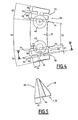
Figure 4 est une vue axiale de derrière d'un élément anti-extrusion de l'ensemble d'étanchéité de laFigure 3 ; - la
Figure 5 est une vue selon la coupe V-V de laFigure 4 ; - la
Figure 6 est une vue analogue à celle de laFigure 2 , montrant une jonction tubulaire présentant un ensemble d'étanchéité selon un deuxième mode de réalisation de l'invention ; [suite page 4 telle que déposée] - la
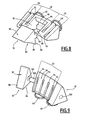
Figure 7 est une vue en perspective de l'ensemble d'étanchéité muni d'éléments de verrouillage et d'éléments anti-extrusion selon le deuxième mode de réalisation de l'invention ; - la
Figure 8 est une vue en perspective d'un élément anti-extrusion et d'un élément de verrouillage à l'état non assemblé de l'ensemble d'étanchéité de laFigure 7 ; - la
Figure 9 montre un élément anti-extrusion selon un troisième mode de réalisation ; et - les
Figures 10 et 11 montrent un élément anti-extrusion selon des quatrième et cinquième modes de réalisation. - La
Figure 1 montre une jonction tubulaire selon l'invention, désignée par la référence générale 2. - La jonction tubulaire 2 comporte un premier élément de canalisation muni d'un bout à emboîtement 4, un second élément de canalisation muni d'un bout uni 6, et un ensemble d'étanchéité 7. Cet ensemble d'étanchéité 7 comprend une garniture d'étanchéité 8 et des éléments anti-extrusion 10.
- La jonction tubulaire 2 définit un axe central X-X se confondant avec l'axe central du bout à emboîtement et de la garniture d'étanchéité 8. Dans ce qui suit les expressions « axialement », « radialement » et « circonférentiellement » seront utilisées par rapport à cet axe central X-X.
- Le bout à emboîtement 4 et le bout uni 6 sont fabriqués par exemple en fonte. De plus, ces éléments de canalisation peuvent être revêtus d'une couche protectrice non représentée.
- Le bout à emboîtement 4 comporte une bride de fixation 14 pour l'assemblage avec un élément de canalisation (non représenté) muni d'une bride correspondante, ainsi qu'une extrémité libre 16, tournée vers le bout uni 6 à l'état non assemblé. Le bout à emboîtement 4 comporte en outre une gorge annulaire intérieure 18 (voir
Figure 2 ). La gorge intérieure 18 forme une paroi de gorge 20 inclinée par rapport à l'axe central X-X. La paroi 20 a une forme tronconique et se rétrécit vers l'extrémité libre 16 du bout à emboîtement. Elle forme un angle α avec l'axe central X-X. - A l'état assemblé de la jonction tubulaire 2, la garniture d'étanchéité 8, munie des éléments anti-extrusion 10, est insérée dans la gorge intérieure 18 du bout à emboîtement. La garniture d'étanchéité 8 est disposée axialement du côté tourné vers la bride de fixation 14, tandis que les éléments anti-extrusion 10, fixés à la garniture 8, sont disposés axialement du côté de l'extrémité libre 16.
- Le bout à emboîtement 4 comporte une surface radialement intérieure 21 qui s'étend entre l'extrémité libre 16 et la paroi de gorge 20. Cette surface 21 est sensiblement cylindrique et est définie par un rayon R autour de l'axe X-X. Le bout uni 6 comporte une surface radialement extérieure 22 cylindrique et définie par un rayon r autour de l'axe X-X. Lors de la fabrication du bout à emboîtement 4 et du bout uni 6, les rayons R et r sont compris dans une gamme de tolérances de fabrication. En conséquence, la surface intérieure 21 et la surface extérieure 22 délimitent entre elles un jeu J = R-r. En fonction des tolérances de fabrication, ce jeu J est situé entre un jeu maximal qui est obtenu lorsque le rayon R est maximal et le rayon r est minimal, ainsi qu'un jeu minimal qui est obtenu lorsque le rayon R est minimal et le rayon r est maximal.
- Le plus couramment cependant, le jeu entre le bout uni et le bout à emboîtement est un jeu moyen qui est situé entre le jeu maximal et le jeu minimal (voir
Figure 2 ). - La garniture d'étanchéité 8 est par exemple fabriquée en caoutchouc. Elle comporte un corps de base 24 annulaire et une lèvre d'étanchéité annulaire 26.
- En se référant à la
Figure 2 , la section transversale de l'élément anti-extrusion 10 est sensiblement triangulaire. L'élément anti-extrusion 10 forme ainsi une face d'application 28 tronconique ayant une composante dirigée radialement vers l'extérieur, une face radialement intérieure 30 et une face de liaison 32 qui est adjacente à la garniture d'étanchéité 8 et qui assure la liaison de l'élément anti-extrusion 10 avec la garniture d'étanchéité 8. La face de liaison 32 s'étend à l'état non sollicité de la garniture 8 radialement par rapport à l'axe central X-X. - Dans la configuration montrée sur la
Figure 2 , la face d'application 28 est inclinée d'un angle β par rapport à l'axe X-X, angle qui est sensiblement identique à l'angle d'inclinaison α de la paroi de gorge 20. La face d'application 28 s'applique donc à plat sur la paroi 20. Par ailleurs, la face d'application 28 et la face de liaison 32 forment à leur jonction, en section radiale, un point de basculement 34 permettant de faire basculer l'élément anti-extrusion 10 autour de la paroi 20. - Les éléments anti-extrusion 10 ont une forme d'arc de cercle autour de l'axe central X-X. Ainsi, les éléments anti-extrusion 10 empêchent que l'élastomère de la garniture d'étanchéité 8 soit extrudé vers l'extérieur à travers l'espace annulaire délimité par la surface extérieure 22 du bout uni 6 et la surface intérieure 21 du bout à emboîtement 4 lors de la mise en pression des éléments de canalisation.
- Les éléments anti-extrusion 10 sont de préférence réalisés en une matière plastique plus dure que la matière de la garniture d'étanchéité, telle du polyamide, du polyéthylène ou du polypropylène.
- Les éléments anti-extrusion 10 sont fixés à la garniture d'étanchéité 8 par tout moyen approprié. Ils peuvent notamment être fixés par collage, surmoulage, encliquetage, vissage ou rivetage. A cette fin, les éléments anti-extrusion comprennent des tétons d'ancrage 40, qui font saillie sur la face de liaison 32. Chaque téton 40 est fixé à la garniture d'étanchéité 8 par surmoulage.
- Avantageusement et afin de garantir une mobilité relative de l'élément anti-extrusion 10, celui-ci est fixé uniquement par le téton d'ancrage 40 à la garniture d'étanchéité 8, la zone de contact entre la surface de liaison 32 et la garniture d'étanchéité 8 étant dépourvue de tout autre liant. La face de liaison 32 est à cet effet disposée librement sur la garniture d'étanchéité 8.
- De plus, l'élément anti-extrusion 10 est dépourvu de tout élément de verrouillage adapté pour verrouiller le bout uni par rapport au bout à emboîtement.
- Comme indiqué sur la
Figure 4 , chaque élément anti-extrusion 10 comporte un domaine circonférentiel dit rigide 50 et deux domaines circonférentiels dits flexibles 52. - Le domaine rigide 50 s'étend par exemple sur plus de 50% de l'étendue circonférentielle de l'élément anti-extrusion 10. En tout cas, le domaine rigide 50 s'étend de manière ininterrompue sur une plage circonférentielle qui est supérieure à une plage circonférentielle de l'un des domaines flexibles 52.
- Le domaine rigide 50 porte au moins en partie les tétons d'ancrage 40, ce qui facilite le montage de l'élément anti-extrusion 10 dans la garniture d'étanchéité 8.
- Chaque domaine flexible 52 forme une extrémité circonférentielle de l'élément anti-extrusion 10, tandis que le domaine rigide 50 forme une partie circonférentielle centrale de cet élément.
- Le domaine rigide 50 a une première rigidité en flexion radiale et chaque domaine flexible 52 a une deuxième rigidité en flexion radiale, qui est inférieure à la première rigidité en flexion radiale.
- A cet effet, chaque domaine flexible 52 comporte des fentes de flexion 54 radiales vides. Chaque fente de flexion 54 est axialement et radialement ouverte. De plus, chaque fente de flexion 54 est axialement traversante. Chaque fente de flexion 54 forme également un fond radial.
- Chaque fente de flexion 54 s'étend sur une zone circonférentielle flexible 56 et délimite une zone circonférentielle rigide 58.
- L'étendue circonférentielle de chaque zone circonférentielle flexible 56 est inférieure à l'étendue circonférentielle du domaine rigide 50. L'étendue circonférentielle de chaque zone circonférentielle rigide 58 est inférieure à l'étendue circonférentielle du domaine rigide 50. De plus, chaque zone circonférentielle rigide 58 a une section transversale qui est identique à la section transversale du domaine rigide 50.
- La rigidité en flexion radiale de chaque zone circonférentielle flexible est inférieure à 50% de la rigidité en flexion radiale de chaque zone circonférentiellement rigide et/ou du domaine rigide 50, notamment inférieure à 40%, 30%, 20% ou 10% de la rigidité en flexion radiale de chaque zone circonférentiellement rigide et/ou du domaine rigide 50. Aussi, la rigidité en flexion radiale de chaque zone circonférentiellement flexible 56 est cependant supérieure à 5% de la rigidité en flexion radiale de chaque zone circonférentiellement rigide 58 et/ou du domaine rigide 50.
- Les fentes de flexion 54 de chaque domaine flexible 52 forment un groupe circonférentiel 60 de fentes de flexion 54. La distance circonférentielle C1 entre deux fentes de flexion 54 adjacentes du même groupe 60 est inférieure à la distance circonférentielle C2 entre une fente de flexion 54 n'appartenant pas au groupe et la fente de flexion 54 la plus proche du même groupe 60.
- Dans chaque zone circonférentielle flexible 56 sont disposées deux fentes de flexion 54 radialement opposées qui forment une âme 64. En se référant à la
Figure 5 , l'âme 64 a une section transversale se rétrécissant vers l'extrémité axiale dirigée vers l'extrémité libre 16 du bout à emboîtement à l'état monté. En particulier, la section transversale de l'âme 64 a approximativement une forme en triangle. - Les fentes de flexion 54 adjacentes d'un même groupe 60 ont des profondeurs radiales P1, P2 différentes l'une de l'autre. Plus particulièrement, la fente de flexion 54 plus proche de l'extrémité circonférentielle a une profondeur P1 supérieure à la profondeur P2 de la fente de flexion 54 plus proche de la partie circonférentielle centrale de l'élément anti-extrusion 10. Ainsi, la flexibilité radiale du domaine flexible 52 varie sur son étendue circonférentielle. Aussi, la flexibilité radiale de chaque domaine flexible 52 augmente du côté circonférentiel central vers l'extrémité circonférentielle.
- Les éléments anti-extrusion 10 sont séparés entre eux par une entretoise circonférentielle 66 venue de matière avec la garniture d'étanchéité 8, cette entretoise 66 ayant une dimension circonférentielle inférieure à la dimension circonférentielle des éléments anti-extrusion 10 afin de ne pas favoriser l'extrusion du matériau constituant la garniture d'étanchéité sous l'effet de la pression intérieure. Ces entretoises 66 améliorent la souplesse de la garniture d'étanchéité 8 et facilitent ainsi sa déformation en vue de son introduction dans le bout à emboîtement.
- Le montage de la jonction tubulaire selon l'invention s'effectue de la manière décrite ci-après.
- Tout d'abord, les éléments anti-extrusion 10 sont fixés sur la garniture d'étanchéité 8. Ainsi, l'ensemble 7 comprenant la garniture d'étanchéité 8 et les éléments anti-extrusion 10 peut être manipulé d'un seul bloc. Ensuite, la garniture d'étanchéité 8, portant les éléments anti-extrusion 10, est légèrement déformée à la main de manière à pouvoir être introduite et disposée dans la gorge intérieure 18 du bout à emboîtement.
- Lors de l'insertion du bout uni 6 dans le bout à emboîtement 4, l'élément anti-extrusion 10 bascule dans le sens horaire sur la
Figure 2 et la lèvre d'étanchéité 26 est comprimée radialement vers l'extérieur, aboutissant ainsi, après emboîtage, à une configuration dans laquelle la face d'application 28 est d'autant plus écartée de la paroi de gorge 20 que le jeu J entre le bout uni et le bout à emboîtement est faible. - Enfin, lors du recul du bout uni 6 sous l'effet d'une pression intérieure élevée, l'élément anti-extrusion 10 pivote d'abord dans le sens anti-horaire jusqu'à ce que sa face d'application 28 vienne en appui contre la paroi de gorge 20. L'élément anti-extrusion 10 se déplace alors axialement vers l'extrémité libre 16 du bout à emboîtement 4 et radialement vers l'intérieur par glissement de la face d'application 28 sur la paroi de gorge 20. On aboutit ainsi à une configuration telle que par exemple celle représentée sur la
Figure 2 . - Dans l'exemple de réalisation décrit, l'angle entre les faces 32 et 28 formant le point de basculement 34 est un angle aigu qui favorise l'ancrage du point de basculement 34 dans la gorge 18 du bout à emboîtement 4 en vue de former un centre de rotation stable.
- Sur la
Figure 6 est représenté en coupe radiale un deuxième mode de réalisation de l'ensemble d'étanchéité selon l'invention, qui diffère de l'ensemble précédemment décrit par ce qui suit. - L'ensemble d'étanchéité 7 comporte des éléments de verrouillage 12. Chaque élément de verrouillage 12 a une section génératrice triangulaire qui s'étend sur une plage angulaire autour de l'axe central X-X.
- L'élément de verrouillage 12 comporte ainsi une face extérieure 80, une face intérieure 82 et une face de liaison 84.
- L'élément de verrouillage 12 comporte au niveau de la jonction entre sa face intérieure 82 et sa face de liaison 84 une dent d'accrochage 86 adaptée pour venir mordre dans la surface extérieure 22 du bout uni. Cette dent 86 comporte une surface d'accrochage dirigée à l'opposé de l'extrémité libre 16.
- L'élément anti-extrusion 10 comporte en outre un évidement de réception 88 axialement ouvert vers l'extrémité libre 16 et radialement traversant (cf.
Figure 8 ). L'élément de verrouillage 12 est inséré dans cet évidement 88 et est fixé à l'élément anti-extrusion 10 par tout moyen approprié, par exemple par surmoulage. L'évidement de réception 88 est ménagé dans le domaine rigide 50. Cet évidement de réception 88 est axialement fermé du côté de la face de liaison 32 par une paroi de base 90 et circonférentiellement fermé des deux côtés par des parois circonférentielles 92. La rigidité en flexion radiale du domaine rigide 50, même en présence de l'évidement de réception 88 et lorsque l'élément de verrouillage 12 est fixé dans cet évidement 88, est supérieure à la rigidité en flexion radiale dans les domaines circonférentiels flexibles 52. - Chaque élément de verrouillage 12 est fixé à un élément anti-extrusion 10. A cet effet, l'élément anti-extrusion 10 comporte une gorge 94, ménagée dans la paroi de base 90 et coopérant par complémentarité de formes avec une nervure 96 faisant saillie sur la face de liaison 84 de l'élément de verrouillage 12.
- Les éléments de verrouillage 12 étant rapportés sur les éléments anti-extrusion 10, il n'est pas nécessaire qu'ils épousent les profils du bout uni 6 et du bout à emboîtement. En conséquence, les éléments de verrouillage 12 ont des profils intérieurs et extérieurs rectilignes et notamment une dent d'accrochage 86 rectiligne. Ceci est avantageux car un même élément de verrouillage 12 peut alors être utilisé avec différents diamètres de tuyaux.
- Chaque élément de verrouillage 12 est un élément fabriqué en une matière ayant une dureté supérieure à celle de la surface du bout uni 6, telle que du métal.
- Le fonctionnement des éléments de verrouillage 12, lors de la mise en pression, diffère en fonction du jeu radial J subsistant entre la surface intérieure 21 et la surface extérieure 22. Ainsi, lorsque ce jeu J est élevé, le verrouillage est obtenu par coincement de l'élément de verrouillage 12 entre le bout uni et le bout à emboîtement, la dent 86 de l'élément de verrouillage mordant dans la surface extérieure 22 du bout uni et sa face extérieure 80 s'appliquant contre la paroi 20 du bout à emboîtement. En revanche, lorsque ce jeu est faible, le verrouillage est obtenu par arc-boutement de l'élément de verrouillage 12 entre la surface extérieure 22 du bout uni et la paroi 20 du bout à emboîtement.
- Il est à noter que l'ensemble d'étanchéité 7 de la
Figure 7 comporte également des éléments anti-extrusion 10 identiques à ceux du premier mode de réalisation, à savoir sans élément de verrouillage 12, les éléments anti-extrusion 10 munis d'un élément de verrouillage 12 et ceux dépourvus d'élément de verrouillage 12 étant disposés régulièrement et alternativement sur tout le pourtour de la garniture d'étanchéité. - Les éléments anti-extrusion 10 munis ou non d'élément de verrouillage 12 sont agencés sur la garniture d'étanchéité 8 en fonction de la force de verrouillage nécessaire.
- La
Figure 9 montre, à l'état non entièrement assemblé, un élément anti-extrusion 10 muni de deux éléments de verrouillage 12 selon une variante de l'invention. - Cette variante diffère de l'élément anti-extrusion 10 et élément de verrouillage 12 de la
Figure 8 par ce qui suit. - L'élément anti-extrusion 10 comporte un seul domaine flexible 52. Ce domaine 52 constitue un domaine circonférentiel central de l'élément anti-extrusion 10. Ainsi, la flexibilité radiale de l'élément anti-extrusion 10 est plus importante dans le domaine central que dans les domaines d'extrémité.
- Le domaine flexible 52 comporte quatre fentes de flexion 54 disposées selon la direction circonférentielle sur la face inférieure 30. Quatre fentes 54 supplémentaires sont disposées sur la face extérieure 28.
- Les fentes de flexion 54 ont toutes la même profondeur radiale, ce qui facilite la fabrication.
- En outre, l'élément anti-extrusion 10 comporte deux ergots de fixation 100 s'étendant du domaine flexible 52 circonférentiellement vers l'extérieur. Les ergots 100 forment les extrémités circonférentielles de l'élément anti-extrusion 10.
- Chaque élément de verrouillage 12 comporte un alésage circonférentiel 102 complémentaire de l'ergot 100. L'élément de verrouillage 12 est enfiché circonférentiellement sur l'ergot, la direction de montage étant donc sensiblement circonférentielle, ce qui rend particulièrement simple et facile le montage des éléments de verrouillage 12 sur l'élément anti-extrusion 10.
- De plus, les éléments de verrouillage 12 peuvent tourner librement sur l'ergot 100 autour de l'axe de l'ergot 100, ce qui leur confère une meilleure aptitude au verrouillage.
- Le fait que chaque élément anti-extrusion 10 porte deux éléments de verrouillage 12 permet également d'augmenter le nombre d'éléments de verrouillage 12 par ensemble 7 sans pour autant modifier le moule de la garniture d'étanchéité 8.
- Sur la
Figure 10 est représenté un élément anti-extrusion 10 et un élément de verrouillage 12. Ces éléments diffèrent des éléments de laFigure 9 par ce qui suit. - L'élément anti-extrusion 10 comporte un seul ergot 100 faisant saillie circonférentiellement.
- Une des extrémités circonférentielles de l'élément anti-extrusion 10 est dépourvue de moyen de fixation et constitue un domaine rigide 50.
- L'élément anti-extrusion 10 comporte en outre un organe de blocage 104 adapté pour s'opposer à une rotation de l'élément de verrouillage 12 autour de l'axe de l'ergot 100. Ainsi, lors de la mise en pression, le déplacement de l'élément de verrouillage 12 est limité. En l'occurrence, l'organe de blocage 104 est constitué par une paroi solidaire de l'élément anti-extrusion 10 s'étendant circonférentiellement.
- La
Figure 11 montre une variante consistant en une combinaison des caractéristiques desFigures 9 et10 . - Ainsi, l'élément anti-extrusion 10 comporte deux ergots 100, dont l'un est visible, et deux éléments de verrouillage 12.
- Pour chaque élément de verrouillage 12, l'élément anti-extrusion 10 comporte un organe de blocage 104.
- Il est à noter que toutes les caractéristiques structurelles et fonctionnelles décrites en liaison avec un mode de réalisation spécifique peuvent être appliquées d'une manière analogue et indépendamment les unes des autres aux autres modes de réalisation.
- En variante, les domaines flexibles 52 peuvent porter d'autres évidements de flexibilité que des fentes de flexion 54, par exemple des trous borgnes. En variante encore, les évidements des domaines flexibles 52 peuvent être radialement traversants.
- L'emplacement dépourvu d'évidement de flexion est la zone ayant la rigidité en flexion radiale la plus élevée de l'élément anti-extrusion. En d'autres termes, l'emplacement dépourvu d'évidement de flexion est la section radiale la plus rigide de cet élément anti-extrusion.
- Un autre aspect de l'invention porte sur un ensemble d'étanchéité et de verrouillage pour jonction tubulaire entre un bout uni 6 et un bout à emboîtement 4, du type comportant
- une garniture d'étanchéité 8 définissant un axe central X-X, et
- au moins un élément anti-extrusion 10 qui est adapté pour empêcher l'extrusion de la garniture d'étanchéité 8 entre le bout uni 6 et le bout à emboîtement 4, et sur lequel est fixé au moins un élément de verrouillage 12 adapté pour verrouiller le bout uni 6 par rapport au bout à emboîtement 4, dans lequel ensemble le ou chaque élément de verrouillage 12 est fixé sur une extrémité circonférentielle de l'élément anti-extrusion.
- Selon un aspect plus particulier de cet ensemble, chaque élément de verrouillage 12 est fixé à l'élément anti-extrusion 10 au moyen d'au moins un organe de fixation, notamment un ergot d'ancrage 100 coopérant avec un alésage 102.
- Selon un autre aspect particulier de cet ensemble, la direction de montage du ou de chaque élément de verrouillage 12 sur l'élément anti-extrusion 10 s'étend sensiblement circonférentiellement.
- Par ailleurs, cet ensemble peut comporter toutes les autres caractéristiques techniques des ensembles décrits précédemment.
Claims (18)
- Ensemble d'étanchéité pour jonction tubulaire entre un bout uni (6) et un bout à emboîtement (4), comportant- une garniture d'étanchéité (8) définissant un axe central (X-X), et- des éléments anti-extrusion (10) qui sont adaptés pour empêcher l'extrusion de la garniture d'étanchéité (8) entre le bout uni (6) et le bout à emboîtement (4),
les éléments anti-extrusion (10) étant fixés à la garniture d'étanchéité (8),
les éléments anti-extrusion (10) étant séparés entre eux par une entretoise circonférentielle (66) venue de matière avec la garniture d'étanchéité,
les éléments anti-extrusion (10) ayant une forme d'arc de cercle autour de l'axe central (X-X)
caractérisé en ce que chaque élément anti-extrusion comporte au moins un premier évidement de flexion (54) adapté pour permettre une flexion radiale de l'élément anti-extrusion, et en ce que la rigidité en flexion radiale de l'élément anti-extrusion (10), à l'emplacement circonférentiel du ou de chaque évidement de flexion (54), est inférieure à 50%, notamment inférieure à 40%, 30%, 20% ou 10%, de la rigidité en flexion radiale à au moins un emplacement circonférentiel dépourvu d'évidement de flexion. - Ensemble selon la revendication 1, caractérisé en ce que le ou chaque évidement de flexion (54) est axialement et/ou radialement ouvert.
- Ensemble selon la revendication 2, caractérisé en ce que le ou chaque évidement de flexion (54) est axialement et/ou radialement traversant.
- Ensemble selon l'une quelconque des revendications précédentes, caractérisé en ce que le ou chaque évidement de flexion est une fente radiale (54).
- Ensemble selon l'une quelconque des revendications précédentes, caractérisé en ce que les éléments anti-extrusion (10) comportent au moins un deuxième évidement de flexion (54).
- Ensemble selon la revendication 5, caractérisé en ce que les premier et deuxième évidements de flexion (54) au moins forment un groupe circonférentiel (60) d'évidements de flexion.
- Ensemble selon la revendication 6, caractérisé en ce que la profondeur radiale (P1 ; P2) varie d'un évidement de flexion à l'autre du groupe circonférentiel d'évidements de flexion.
- Ensemble selon la revendication 7, caractérisé en ce que les profondeurs radiales (P1, P2) de deux évidements de flexion (54) adjacentes décroissent vers la partie circonférentielle centrale de l'élément anti-extrusion (10).
- Ensemble selon la revendication 8, caractérisé en ce que la distance circonférentielle (C1) entre les évidements de flexion du groupe circonférentiel d'évidements est inférieure à la distance circonférentielle (C2) entre un autre évidement de flexion n'appartenant pas à ce groupe circonférentiel et l'évidement de flexion le plus proche de ce groupe circonférentiel.
- Ensemble selon l'une quelconque des revendications précédentes, caractérisé en ce que le ou chaque évidement de flexion (54) est disposé sur au moins un domaine (52) d'extrémité circonférentielle de l'élément anti-extrusion, de telle sorte que la flexibilité radiale de l'élément anti-extrusion (10) est plus importante dans ce domaine d'extrémité que dans un domaine (50) circonférentiellement central de l'élément anti-extrusion.
- Ensemble selon l'une quelconque des revendications 1 à 9, caractérisé en ce que le ou chaque évidement de flexion (54) est disposé sur un domaine (52) circonférentiellement central de l'élément anti-extrusion, de sorte que la flexibilité radiale de l'élément anti-extrusion est plus importante dans le domaine circonférentiellement central que dans des domaines d'extrémité circonférentielle de l'élément anti-extrusion.
- Ensemble selon l'une quelconque des revendications précédentes, caractérisé en ce que les évidements de flexion comportent au moins deux évidements de flexion radialement opposés et définissant une âme (64) entre eux, en particulier en ce que l'âme (64) a une section transversale se rétrécissant vers une extrémité axiale de l'élément anti-extrusion.
- Ensemble selon l'une quelconque des revendications précédentes, caractérisé en ce qu'il comporte au moins un élément de verrouillage (12) adapté pour verrouiller le bout uni (6) par rapport au bout à emboîtement (4).
- Ensemble selon la revendication 13, caractérisé en ce que le ou chaque élément de verrouillage (12) est fixé à un élément anti-extrusion (10) par tout moyen rapproprié.
- Ensemble selon l'une des revendications précédentes 13 ou 14, caractérisé en ce que le ou chaque élément de verrouillage (12) est fixé à l'élément anti-extrusion (10) au moyen d'au moins un organe de fixation, notamment un ergot d'ancrage (100).
- Ensemble selon la revendication 15, caractérisé en ce que le ou chaque élément de verrouillage (12) est fixé sur une extrémité circonférentielle de l'élément anti-extrusion.
- Ensemble selon la revendication 16, caractérisé en ce que la direction de montage du ou de chaque élément de verrouillage sur l'élément anti-extrusion s'étend sensiblement circonférentiellement.
- Jonction tubulaire, du type comprenant- un bout à emboîtement (4) d'un premier élément de canalisation, le bout à emboîtement (4) s'étendant selon un axe central (X-X), étant muni d'une gorge intérieure (18) et d'une extrémité libre (16) dans laquelle est inséré un bout uni (6) d'un deuxième élément de canalisation, la gorge intérieure (18) formant une paroi de gorge (20) qui est inclinée par rapport à l'axe central (X-X) et qui se rétrécit vers l'extrémité libre (16) du bout à emboîtement (4),
caractérisée en ce qu'elle comprend un ensemble d'étanchéité selon l'une quelconque des revendications précédentes disposé dans la gorge intérieure (18).
Applications Claiming Priority (2)
| Application Number | Priority Date | Filing Date | Title |
|---|---|---|---|
| FR0858170A FR2939177B1 (fr) | 2008-12-01 | 2008-12-01 | Ensemble d'etancheite et jonction tubulaire correspondante |
| PCT/FR2009/052338 WO2010063931A2 (fr) | 2008-12-01 | 2009-11-30 | Ensemble d'étanchéité et jonction tubulaire correspondante |
Publications (2)
| Publication Number | Publication Date |
|---|---|
| EP2359045A2 EP2359045A2 (fr) | 2011-08-24 |
| EP2359045B1 true EP2359045B1 (fr) | 2015-09-30 |
Family
ID=40668170
Family Applications (1)
| Application Number | Title | Priority Date | Filing Date |
|---|---|---|---|
| EP09821423.2A Not-in-force EP2359045B1 (fr) | 2008-12-01 | 2009-11-30 | Ensemble d'étanchéité et jonction tubulaire correspondante |
Country Status (4)
| Country | Link |
|---|---|
| EP (1) | EP2359045B1 (fr) |
| ES (1) | ES2553422T3 (fr) |
| FR (1) | FR2939177B1 (fr) |
| WO (1) | WO2010063931A2 (fr) |
Families Citing this family (3)
| Publication number | Priority date | Publication date | Assignee | Title |
|---|---|---|---|---|
| EP2664833B1 (fr) * | 2012-05-14 | 2016-04-27 | Trelleborg Pipe Seals Lelystad BV | Joint de retenue |
| FR2995651B1 (fr) * | 2012-09-19 | 2015-05-01 | Saint Gobain Pont A Mousson | Ensemble d'etancheite pour jonction tubulaire et jonction tubulaire correspondante |
| US9951869B2 (en) | 2015-02-04 | 2018-04-24 | Trelleborg Pipe Seals Lelystad BV | Seal for belled pipe |
Family Cites Families (5)
| Publication number | Priority date | Publication date | Assignee | Title |
|---|---|---|---|---|
| GB2043802B (en) * | 1979-03-14 | 1983-03-09 | Gustavsberg Ab | Seals |
| SE463664B (sv) * | 1986-04-17 | 1991-01-07 | Forsheda Ab | Formnings- och taetningsring |
| AT503187B1 (de) * | 2006-02-10 | 2008-02-15 | Semperit Ag Holding | Dichtring und dichtungsvorrichtung mit dem dichtring |
| AT504096B1 (de) * | 2006-07-17 | 2008-07-15 | Semperit Ag Holding | Dichtungsring und verbindungsvorrichtung für eine muffenverbindung |
| US7774915B2 (en) * | 2007-05-16 | 2010-08-17 | S & B Technical Products, Inc. | Ductile iron pressure fit gasket |
-
2008
- 2008-12-01 FR FR0858170A patent/FR2939177B1/fr not_active Expired - Fee Related
-
2009
- 2009-11-30 ES ES09821423.2T patent/ES2553422T3/es active Active
- 2009-11-30 WO PCT/FR2009/052338 patent/WO2010063931A2/fr not_active Ceased
- 2009-11-30 EP EP09821423.2A patent/EP2359045B1/fr not_active Not-in-force
Also Published As
| Publication number | Publication date |
|---|---|
| FR2939177A1 (fr) | 2010-06-04 |
| EP2359045A2 (fr) | 2011-08-24 |
| WO2010063931A3 (fr) | 2010-07-29 |
| ES2553422T3 (es) | 2015-12-09 |
| WO2010063931A2 (fr) | 2010-06-10 |
| FR2939177B1 (fr) | 2011-07-08 |
Similar Documents
| Publication | Publication Date | Title |
|---|---|---|
| EP2084446B1 (fr) | Jonction tubulaire | |
| EP0541472B1 (fr) | Joint verrouillé pour canalisations | |
| EP0893641B1 (fr) | Dispositif pour l'assemblage de deux éléments de canalisation, et assemblages d'éléments de canalisation en comportant application | |
| EP0310534B1 (fr) | Garniture d'étanchéité pour joints verrouillés télescopiques | |
| EP2878873B1 (fr) | Dispositif de raccordement rapide de type cartouche | |
| EP0870967A1 (fr) | Joint verrouillé entre éléments de canalisation et jonc fendu métallique utilisable dand un tel joint | |
| WO2014170590A1 (fr) | Verrou pour raccordement tubulaire | |
| EP2633218B1 (fr) | Assemblage avec garniture d'étanchéité avec insert de verrouillage. | |
| WO2006035141A1 (fr) | Garniture d'etancheite et assemblage correspondant | |
| EP2359045A2 (fr) | Ensemble d'étanchéité et jonction tubulaire correspondante | |
| EP1977152B1 (fr) | Jonction tubulaire | |
| EP1860362B1 (fr) | Raccord de liaison | |
| EP2923132B1 (fr) | Ensemble d'étanchéité pour jonction tubulaire et jonction tubulaire correspondante | |
| FR2995651A1 (fr) | Ensemble d'etancheite pour jonction tubulaire et jonction tubulaire correspondante | |
| EP1360436A1 (fr) | Garniture d'etancheite pour assemblage d'elements tubulaires de circuits de fluides | |
| EP1817520B1 (fr) | Douille de guidage a insertion facilitee dans un alesage d'un raccord et raccord correspondant | |
| EP4153894B1 (fr) | Assemblage etanche et verrouille | |
| FR3156181A1 (fr) | Jonction tubulaire comprenant une garniture d’étanchéité avec inserts de verrouillage fixés par complémentarité de forme | |
| EP1605195A1 (fr) | Système de raccordement de pièce(s) tubulaire(s) et son procédé de montage | |
| FR2640679A1 (fr) | Tube d'injection pour colonne articulee de forage a injection d'eau | |
| EP3346174B1 (fr) | Dispositif de raccord etanche destine a vehiculer un fluide | |
| FR3084119A1 (fr) | Moyens de fixation d'une piece rapportee contre l'extremite d'une proeminence cylindrique dans un sonar, sonar correspondant | |
| EP3969663A1 (fr) | Joint de dilatation carrossable |
Legal Events
| Date | Code | Title | Description |
|---|---|---|---|
| PUAI | Public reference made under article 153(3) epc to a published international application that has entered the european phase |
Free format text: ORIGINAL CODE: 0009012 |
|
| 17P | Request for examination filed |
Effective date: 20110531 |
|
| AK | Designated contracting states |
Kind code of ref document: A2 Designated state(s): AT BE BG CH CY CZ DE DK EE ES FI FR GB GR HR HU IE IS IT LI LT LU LV MC MK MT NL NO PL PT RO SE SI SK SM TR |
|
| RIN1 | Information on inventor provided before grant (corrected) |
Inventor name: GENELOT, PIERRE Inventor name: BRAHIMI, FRANCIS Inventor name: VITEL, JEAN-PIERRE |
|
| DAX | Request for extension of the european patent (deleted) | ||
| RAP1 | Party data changed (applicant data changed or rights of an application transferred) |
Owner name: SAINT-GOBAIN PAM |
|
| REG | Reference to a national code |
Ref country code: DE Ref legal event code: R079 Ref document number: 602009034151 Country of ref document: DE Free format text: PREVIOUS MAIN CLASS: F16L0021030000 Ipc: F16L0037084000 |
|
| GRAP | Despatch of communication of intention to grant a patent |
Free format text: ORIGINAL CODE: EPIDOSNIGR1 |
|
| GRAJ | Information related to disapproval of communication of intention to grant by the applicant or resumption of examination proceedings by the epo deleted |
Free format text: ORIGINAL CODE: EPIDOSDIGR1 |
|
| GRAP | Despatch of communication of intention to grant a patent |
Free format text: ORIGINAL CODE: EPIDOSNIGR1 |
|
| RIC1 | Information provided on ipc code assigned before grant |
Ipc: F16L 37/084 20060101AFI20150323BHEP Ipc: F16L 21/03 20060101ALI20150323BHEP |
|
| INTG | Intention to grant announced |
Effective date: 20150414 |
|
| INTG | Intention to grant announced |
Effective date: 20150424 |
|
| GRAS | Grant fee paid |
Free format text: ORIGINAL CODE: EPIDOSNIGR3 |
|
| GRAA | (expected) grant |
Free format text: ORIGINAL CODE: 0009210 |
|
| AK | Designated contracting states |
Kind code of ref document: B1 Designated state(s): AT BE BG CH CY CZ DE DK EE ES FI FR GB GR HR HU IE IS IT LI LT LU LV MC MK MT NL NO PL PT RO SE SI SK SM TR |
|
| REG | Reference to a national code |
Ref country code: CH Ref legal event code: EP Ref country code: GB Ref legal event code: FG4D Free format text: NOT ENGLISH |
|
| REG | Reference to a national code |
Ref country code: AT Ref legal event code: REF Ref document number: 752625 Country of ref document: AT Kind code of ref document: T Effective date: 20151015 |
|
| REG | Reference to a national code |
Ref country code: IE Ref legal event code: FG4D Free format text: LANGUAGE OF EP DOCUMENT: FRENCH |
|
| REG | Reference to a national code |
Ref country code: FR Ref legal event code: PLFP Year of fee payment: 7 |
|
| REG | Reference to a national code |
Ref country code: DE Ref legal event code: R096 Ref document number: 602009034151 Country of ref document: DE |
|
| REG | Reference to a national code |
Ref country code: ES Ref legal event code: FG2A Ref document number: 2553422 Country of ref document: ES Kind code of ref document: T3 Effective date: 20151209 |
|
| REG | Reference to a national code |
Ref country code: NL Ref legal event code: FP |
|
| PG25 | Lapsed in a contracting state [announced via postgrant information from national office to epo] |
Ref country code: GR Free format text: LAPSE BECAUSE OF FAILURE TO SUBMIT A TRANSLATION OF THE DESCRIPTION OR TO PAY THE FEE WITHIN THE PRESCRIBED TIME-LIMIT Effective date: 20151231 Ref country code: FI Free format text: LAPSE BECAUSE OF FAILURE TO SUBMIT A TRANSLATION OF THE DESCRIPTION OR TO PAY THE FEE WITHIN THE PRESCRIBED TIME-LIMIT Effective date: 20150930 Ref country code: LV Free format text: LAPSE BECAUSE OF FAILURE TO SUBMIT A TRANSLATION OF THE DESCRIPTION OR TO PAY THE FEE WITHIN THE PRESCRIBED TIME-LIMIT Effective date: 20150930 Ref country code: NO Free format text: LAPSE BECAUSE OF FAILURE TO SUBMIT A TRANSLATION OF THE DESCRIPTION OR TO PAY THE FEE WITHIN THE PRESCRIBED TIME-LIMIT Effective date: 20151230 Ref country code: LT Free format text: LAPSE BECAUSE OF FAILURE TO SUBMIT A TRANSLATION OF THE DESCRIPTION OR TO PAY THE FEE WITHIN THE PRESCRIBED TIME-LIMIT Effective date: 20150930 |
|
| REG | Reference to a national code |
Ref country code: LT Ref legal event code: MG4D |
|
| REG | Reference to a national code |
Ref country code: AT Ref legal event code: MK05 Ref document number: 752625 Country of ref document: AT Kind code of ref document: T Effective date: 20150930 |
|
| PG25 | Lapsed in a contracting state [announced via postgrant information from national office to epo] |
Ref country code: HR Free format text: LAPSE BECAUSE OF FAILURE TO SUBMIT A TRANSLATION OF THE DESCRIPTION OR TO PAY THE FEE WITHIN THE PRESCRIBED TIME-LIMIT Effective date: 20150930 Ref country code: SE Free format text: LAPSE BECAUSE OF FAILURE TO SUBMIT A TRANSLATION OF THE DESCRIPTION OR TO PAY THE FEE WITHIN THE PRESCRIBED TIME-LIMIT Effective date: 20150930 |
|
| PG25 | Lapsed in a contracting state [announced via postgrant information from national office to epo] |
Ref country code: CZ Free format text: LAPSE BECAUSE OF FAILURE TO SUBMIT A TRANSLATION OF THE DESCRIPTION OR TO PAY THE FEE WITHIN THE PRESCRIBED TIME-LIMIT Effective date: 20150930 Ref country code: SK Free format text: LAPSE BECAUSE OF FAILURE TO SUBMIT A TRANSLATION OF THE DESCRIPTION OR TO PAY THE FEE WITHIN THE PRESCRIBED TIME-LIMIT Effective date: 20150930 Ref country code: EE Free format text: LAPSE BECAUSE OF FAILURE TO SUBMIT A TRANSLATION OF THE DESCRIPTION OR TO PAY THE FEE WITHIN THE PRESCRIBED TIME-LIMIT Effective date: 20150930 Ref country code: IS Free format text: LAPSE BECAUSE OF FAILURE TO SUBMIT A TRANSLATION OF THE DESCRIPTION OR TO PAY THE FEE WITHIN THE PRESCRIBED TIME-LIMIT Effective date: 20160130 |
|
| PG25 | Lapsed in a contracting state [announced via postgrant information from national office to epo] |
Ref country code: AT Free format text: LAPSE BECAUSE OF FAILURE TO SUBMIT A TRANSLATION OF THE DESCRIPTION OR TO PAY THE FEE WITHIN THE PRESCRIBED TIME-LIMIT Effective date: 20150930 Ref country code: PL Free format text: LAPSE BECAUSE OF FAILURE TO SUBMIT A TRANSLATION OF THE DESCRIPTION OR TO PAY THE FEE WITHIN THE PRESCRIBED TIME-LIMIT Effective date: 20150930 Ref country code: PT Free format text: LAPSE BECAUSE OF FAILURE TO SUBMIT A TRANSLATION OF THE DESCRIPTION OR TO PAY THE FEE WITHIN THE PRESCRIBED TIME-LIMIT Effective date: 20160201 Ref country code: RO Free format text: LAPSE BECAUSE OF FAILURE TO SUBMIT A TRANSLATION OF THE DESCRIPTION OR TO PAY THE FEE WITHIN THE PRESCRIBED TIME-LIMIT Effective date: 20150930 |
|
| PG25 | Lapsed in a contracting state [announced via postgrant information from national office to epo] |
Ref country code: MC Free format text: LAPSE BECAUSE OF FAILURE TO SUBMIT A TRANSLATION OF THE DESCRIPTION OR TO PAY THE FEE WITHIN THE PRESCRIBED TIME-LIMIT Effective date: 20150930 |
|
| REG | Reference to a national code |
Ref country code: CH Ref legal event code: PL |
|
| REG | Reference to a national code |
Ref country code: DE Ref legal event code: R097 Ref document number: 602009034151 Country of ref document: DE |
|
| PG25 | Lapsed in a contracting state [announced via postgrant information from national office to epo] |
Ref country code: CH Free format text: LAPSE BECAUSE OF NON-PAYMENT OF DUE FEES Effective date: 20151130 Ref country code: LI Free format text: LAPSE BECAUSE OF NON-PAYMENT OF DUE FEES Effective date: 20151130 |
|
| PLBE | No opposition filed within time limit |
Free format text: ORIGINAL CODE: 0009261 |
|
| STAA | Information on the status of an ep patent application or granted ep patent |
Free format text: STATUS: NO OPPOSITION FILED WITHIN TIME LIMIT |
|
| REG | Reference to a national code |
Ref country code: IE Ref legal event code: MM4A |
|
| PG25 | Lapsed in a contracting state [announced via postgrant information from national office to epo] |
Ref country code: DK Free format text: LAPSE BECAUSE OF FAILURE TO SUBMIT A TRANSLATION OF THE DESCRIPTION OR TO PAY THE FEE WITHIN THE PRESCRIBED TIME-LIMIT Effective date: 20150930 |
|
| 26N | No opposition filed |
Effective date: 20160701 |
|
| REG | Reference to a national code |
Ref country code: FR Ref legal event code: PLFP Year of fee payment: 8 |
|
| PG25 | Lapsed in a contracting state [announced via postgrant information from national office to epo] |
Ref country code: IE Free format text: LAPSE BECAUSE OF NON-PAYMENT OF DUE FEES Effective date: 20151130 |
|
| PG25 | Lapsed in a contracting state [announced via postgrant information from national office to epo] |
Ref country code: SI Free format text: LAPSE BECAUSE OF FAILURE TO SUBMIT A TRANSLATION OF THE DESCRIPTION OR TO PAY THE FEE WITHIN THE PRESCRIBED TIME-LIMIT Effective date: 20150930 |
|
| PG25 | Lapsed in a contracting state [announced via postgrant information from national office to epo] |
Ref country code: HU Free format text: LAPSE BECAUSE OF FAILURE TO SUBMIT A TRANSLATION OF THE DESCRIPTION OR TO PAY THE FEE WITHIN THE PRESCRIBED TIME-LIMIT; INVALID AB INITIO Effective date: 20091130 Ref country code: BG Free format text: LAPSE BECAUSE OF FAILURE TO SUBMIT A TRANSLATION OF THE DESCRIPTION OR TO PAY THE FEE WITHIN THE PRESCRIBED TIME-LIMIT Effective date: 20150930 Ref country code: SM Free format text: LAPSE BECAUSE OF FAILURE TO SUBMIT A TRANSLATION OF THE DESCRIPTION OR TO PAY THE FEE WITHIN THE PRESCRIBED TIME-LIMIT Effective date: 20150930 |
|
| PG25 | Lapsed in a contracting state [announced via postgrant information from national office to epo] |
Ref country code: CY Free format text: LAPSE BECAUSE OF FAILURE TO SUBMIT A TRANSLATION OF THE DESCRIPTION OR TO PAY THE FEE WITHIN THE PRESCRIBED TIME-LIMIT Effective date: 20150930 |
|
| PG25 | Lapsed in a contracting state [announced via postgrant information from national office to epo] |
Ref country code: TR Free format text: LAPSE BECAUSE OF FAILURE TO SUBMIT A TRANSLATION OF THE DESCRIPTION OR TO PAY THE FEE WITHIN THE PRESCRIBED TIME-LIMIT Effective date: 20150930 Ref country code: MT Free format text: LAPSE BECAUSE OF FAILURE TO SUBMIT A TRANSLATION OF THE DESCRIPTION OR TO PAY THE FEE WITHIN THE PRESCRIBED TIME-LIMIT Effective date: 20150930 |
|
| REG | Reference to a national code |
Ref country code: FR Ref legal event code: PLFP Year of fee payment: 9 |
|
| PGFP | Annual fee paid to national office [announced via postgrant information from national office to epo] |
Ref country code: LU Payment date: 20171108 Year of fee payment: 9 |
|
| PGFP | Annual fee paid to national office [announced via postgrant information from national office to epo] |
Ref country code: DE Payment date: 20171121 Year of fee payment: 9 Ref country code: NL Payment date: 20171115 Year of fee payment: 9 |
|
| PGFP | Annual fee paid to national office [announced via postgrant information from national office to epo] |
Ref country code: IT Payment date: 20171123 Year of fee payment: 9 Ref country code: GB Payment date: 20171129 Year of fee payment: 9 Ref country code: ES Payment date: 20171201 Year of fee payment: 9 Ref country code: BE Payment date: 20170925 Year of fee payment: 9 |
|
| PG25 | Lapsed in a contracting state [announced via postgrant information from national office to epo] |
Ref country code: MK Free format text: LAPSE BECAUSE OF FAILURE TO SUBMIT A TRANSLATION OF THE DESCRIPTION OR TO PAY THE FEE WITHIN THE PRESCRIBED TIME-LIMIT Effective date: 20150930 |
|
| REG | Reference to a national code |
Ref country code: FR Ref legal event code: PLFP Year of fee payment: 10 |
|
| PGFP | Annual fee paid to national office [announced via postgrant information from national office to epo] |
Ref country code: FR Payment date: 20181011 Year of fee payment: 10 |
|
| REG | Reference to a national code |
Ref country code: DE Ref legal event code: R119 Ref document number: 602009034151 Country of ref document: DE |
|
| REG | Reference to a national code |
Ref country code: NL Ref legal event code: MM Effective date: 20181201 |
|
| GBPC | Gb: european patent ceased through non-payment of renewal fee |
Effective date: 20181130 |
|
| PG25 | Lapsed in a contracting state [announced via postgrant information from national office to epo] |
Ref country code: LU Free format text: LAPSE BECAUSE OF NON-PAYMENT OF DUE FEES Effective date: 20181130 |
|
| REG | Reference to a national code |
Ref country code: BE Ref legal event code: MM Effective date: 20181130 |
|
| PG25 | Lapsed in a contracting state [announced via postgrant information from national office to epo] |
Ref country code: NL Free format text: LAPSE BECAUSE OF NON-PAYMENT OF DUE FEES Effective date: 20181201 |
|
| PG25 | Lapsed in a contracting state [announced via postgrant information from national office to epo] |
Ref country code: IT Free format text: LAPSE BECAUSE OF NON-PAYMENT OF DUE FEES Effective date: 20181130 Ref country code: DE Free format text: LAPSE BECAUSE OF NON-PAYMENT OF DUE FEES Effective date: 20190601 |
|
| PG25 | Lapsed in a contracting state [announced via postgrant information from national office to epo] |
Ref country code: BE Free format text: LAPSE BECAUSE OF NON-PAYMENT OF DUE FEES Effective date: 20181130 |
|
| PG25 | Lapsed in a contracting state [announced via postgrant information from national office to epo] |
Ref country code: GB Free format text: LAPSE BECAUSE OF NON-PAYMENT OF DUE FEES Effective date: 20181130 |
|
| REG | Reference to a national code |
Ref country code: ES Ref legal event code: FD2A Effective date: 20200108 |
|
| PG25 | Lapsed in a contracting state [announced via postgrant information from national office to epo] |
Ref country code: ES Free format text: LAPSE BECAUSE OF NON-PAYMENT OF DUE FEES Effective date: 20181201 |
|
| PG25 | Lapsed in a contracting state [announced via postgrant information from national office to epo] |
Ref country code: FR Free format text: LAPSE BECAUSE OF NON-PAYMENT OF DUE FEES Effective date: 20191130 |