EP2358488B1 - Casting equipment for the casting of sheet ingot - Google Patents
Casting equipment for the casting of sheet ingot Download PDFInfo
- Publication number
- EP2358488B1 EP2358488B1 EP09827793.2A EP09827793A EP2358488B1 EP 2358488 B1 EP2358488 B1 EP 2358488B1 EP 09827793 A EP09827793 A EP 09827793A EP 2358488 B1 EP2358488 B1 EP 2358488B1
- Authority
- EP
- European Patent Office
- Prior art keywords
- long side
- casting
- mould
- side walls
- equipment
- Prior art date
- Legal status (The legal status is an assumption and is not a legal conclusion. Google has not performed a legal analysis and makes no representation as to the accuracy of the status listed.)
- Active
Links
Images




Classifications
-
- B—PERFORMING OPERATIONS; TRANSPORTING
- B22—CASTING; POWDER METALLURGY
- B22D—CASTING OF METALS; CASTING OF OTHER SUBSTANCES BY THE SAME PROCESSES OR DEVICES
- B22D11/00—Continuous casting of metals, i.e. casting in indefinite lengths
- B22D11/04—Continuous casting of metals, i.e. casting in indefinite lengths into open-ended moulds
- B22D11/05—Continuous casting of metals, i.e. casting in indefinite lengths into open-ended moulds into moulds having adjustable walls
-
- B—PERFORMING OPERATIONS; TRANSPORTING
- B22—CASTING; POWDER METALLURGY
- B22D—CASTING OF METALS; CASTING OF OTHER SUBSTANCES BY THE SAME PROCESSES OR DEVICES
- B22D11/00—Continuous casting of metals, i.e. casting in indefinite lengths
- B22D11/08—Accessories for starting the casting procedure
Definitions
- the casting speed is normally limited by the tendency of heat crack formation in the ingot being cast when the speed is too high.
- US patent No. 5,931,216 relates to adjustable continuous casting moulds for manufacturing continuously cast ingots of different dimensions where the object is to provide an adjustable mould which provides rapid change to the required ingot cross section based on the one and same mould.
- An important disadvantage with this solution is that the shape of the mould has no means to compensate for casting speed or change of dimension of the mould having in turn bad effect on ingot geometry.
- Document US4030536A discloses an apparatus for continuously casting a substantially rectangular ingot, having a rectangular mould for receiving and containing a supply of molten metal, said mould having an open outlet end and side walls formed of heat-conductive metal, at least the long side walls of the mould being curvable, for substantially their full extent in the direction of advance of metal through the mould to and including their margins at the outlet end of the mould, about an axis of curvature parallel to said last-mentioned direction; means for applying coolant liquid to the walls of the mould around its periphery; and means for progressively curving at least said long side walls convexly outwardly about said axis.
- Figs 1 and 2 shows, as stated above, an equipment 1 for the semi-continuous direct chill (DC) casting of sheet ingot or slabs of different dimensions, in particular for rolling, requiring large ingots with rectangular cross section of the above-mentioned kind.
- the equipment as shown in Figs. 1 and 2 comprises two moulds 7 provided in parallel in a mould frame 2, each mould 7 including a pair of facing side walls 3 and a pair of facing end walls 4.
- the walls defines a mould cavity 5 with an upwardly open inlet for the supply of metal and a downwardly facing outlet provided with a starter block 6 connected to a movable support (not shown in the figures) and which prior to each casting sequence closes the downwardly facing opening.
- the equipment further includes means for cooling the metal comprising supply means for water and water jet nozzles arranged in the lower part of the walls 3, 4 along the periphery of the mould 7 (not further shown).
- the beams 10 with the short end walls 4 may be adjusted (moved in direction x as denoted in the figure) by means of electric motors 13 provided on each side of the mould via a gear (not further shown) with worm screw driving means 14, 15.
- the motors 13 may preferably be controlled by a computer, and the short end walls 4 thereby adjusted, in accordance with a preset dimension scheme with (such as) 50 mm dimension steps as indicated above, or be freely operated to a desired dimension.
- the short end walls are held in position between the long side walls 3 by means of a securing arrangement 16 provided on the movable beam 10.
- the securing arrangement 16 may be a mechanical device or piston/cylinder device, preferably a pneumatic jack device 16 as shown in Fig. 4 pressing with a pre set force against the long side walls 3 from the outside in direction of the arrow F y as shown in the figure.
- Fig. 5 shows a horizontal view of the equipment shown in Fig. 1 and 2 , including the mechanism (means) for flexing the moulds, but for clarity reason excluding the mechanism (means) for adjusting the size of the mould of the casting equipment as shown in Fig. 3 .
- Fig. 6 shows in larger scale and in perspective part of the equipment in Fig. 5
- Each of the long side walls 3 for each mould 7 are at their respective ends as stated above fixed to the frame 2 by means of brackets 9, but at their middle part attached to adjusting beams 17 arranged in parallel with said side walls 3.
- the long side walls 3 are attached to the beams via an adjustable stiffening arrangement 33 (further explained below).
- the adjusting beams 17 are of greater length than the long side walls 3 and are each at their respective ends connected to pull/push bars 18, 19 via connectors in the form of friction grip clamping devices or the like 20 (not further shown).
- the pull/push bars are provided in parallel with the short end walls and are adapted for axial movement through holders 21 with slide bearings (not shown as such) by means of an actuating mechanism 22.
- the actuating mechanism includes two lever arms, one 23 rotatably provided on the left hand side of the frame 2 (as shown in the figure) and another 24 rotatably provided on the right hand side of the frame and being linked to one another through a link arm 25, and an actuator such as a cylinder/piston device 26 connected with the lever arm 24 provided to rotate the lever arm 24 as well as the lever arm 23 via the link arm 25.
- an actuator such as a cylinder/piston device 26 connected with the lever arm 24 provided to rotate the lever arm 24 as well as the lever arm 23 via the link arm 25.
- the lever arm 24 is directly connected to the actuator 26 via a link and the flexing of the long side walls 3 of mould is obtained by moving the adjusting beams 17 outwardly from or inwardly towards the centre of the mould 7 by means of the actuator through axial movement of the pull/push bars 18, 19, 25 via the lever arms 23, 24 respectively.
- the flexible middle part of the long side walls 3 are thereby adjusted inwardly or outwardly to adapt to the desired sheet ingot.
- the transmission ratio of the actuating mechanism and thereby the flexing of the side walls, is defined by the length of the arms of the levers 23, 24.
- the actuator 26 may suitably be in the form of hydraulic piston/cylinder device with an internal piston sensor, where the piston may be controlled by means of a PLC (Programmable Logic Control) via a servo valve (or proportional valve) on the basis of a predetermined pattern of flexing depending on the dimension of the sheet ingot to be cast, the alloy composition and the casting speed.
- PLC Programmable Logic Control
- servo valve or proportional valve
- the stiffening arrangement 33 in conjunction with the flexing long side walls 3 represents an important feature of the invention and enables adjustment of the stiffness of the middle part of the long side walls in relation to the size of the dimension of the ingot to be cast. Thus, if the dimension of the ingot is increased, the stiffness of the middle part of the long wall needs to be increased over a larger part of the wall as well.
- the stiffness is calculated on the basis of suitable algorithm which is not further explained herein.
- the stiffening arrangement 33 as such (design) is, however, further shown in details in Figs. 7 and 8 .
- Fig 7 a) shows the flexible long side wall 3 with an integrated stiffening part 32.
- the stiffening part 32 stretches over a length of the middle part of the long side wall 3 on the outside of the wall (relative to the mould cavity) and has an elevated shape from its ends towards the middle (triangular shape).
- a stiffening intermediate plate 28 is adapted to fit with the stiffening part 32 and is connected to the long side wall and stiffening part 32, as further shown in Figs. 7c ) and Fig 8 , by means of through going bolts 30.
- Fig. 8 shows in addition the long side wall 3 and stiffening arrangement 33 the adjusting beam 17 (described above) and which in turn is connected to the stiffening plate 28 by means of connecting bolts 31.
Landscapes
- Engineering & Computer Science (AREA)
- Mechanical Engineering (AREA)
- Continuous Casting (AREA)
Description
- The present invention relates to equipment for the semi-continuous direct chill (DC) casting of sheet ingot or slabs of different dimensions, in particular ingot or slabs for rolling thin sheet, including a mould frame with a pair of facing side walls and a pair of facing end walls, the walls defining a mould with an upwardly open inlet for the supply of metal and a downwardly facing outlet provided with a starter block on a movable support which prior to each casting closes the downwardly facing opening and where at least one side wall and/or one end wall can be displaced to enable casting of ingots with different dimensions, the equipment further including means for cooling the metal.
- When casting large rectangular-section ingots to be used in the production of rolled products It is customary to impart a small amount of convex curvature to the long side walls of the mould to counteract the greater metal shrinkage (pull-in) which takes place near the middle of the wide side faces of the ingot during solidification as compared with locations near the narrow end faces of the ingot. The shrinkage (pull-in) of the metal is proportional to the extension of the non-frozen metal in the ingot after casting conditions are stabilised. During the casting of large ingots the extension of melted metal in the lengthways direction of the ingot (the sump depth) may be up to 0,8 meter or more depending on the size of the ingot.
- It is primarily the casting speed that influences the extension of the marsh, because it is the thermal conductivity of the material that limits the cooling speed in the middle of the ingot. The amount of water that is jetted onto the ingot surface on the underside of the mould represents a cooling capacity that goes beyond the amount of heat that is transferred to the surface by heat conduction.
- With regard to both metallurgy and productivity it is desirable to apply the highest casting speed possible. The casting speed is normally limited by the tendency of heat crack formation in the ingot being cast when the speed is too high.
- In the initial stage of a casting operation the cooling will be slow and there will be a contraction in the ingot being cast caused by the difference in specific density between the melted and the frozen metal, together with the thermal coefficient of expansion. The metal that initially has frozen, will be of somewhat reduced shape in relation to the geometry of the casting mould. Because of the above-mentioned curvature of the widest faces of the casting mould, the ingot being cast will assume a convex shape in the initial stage of the casting operation. The convexity will gradually reduce until stable conditions with respect to the sump dept in the ingot being cast are stabilized.
- The operating manual of a rolling mill specifies that the rolling surfaces should be straight (without any concavity or convexity in the rolling surfaces). To meet this requirement the casting moulds have to be designed with a curvature (flexing) of the side walls corresponding to the estimated shrinkage/contraction of the ingot to be cast.
- The applicants own
EP 0 796 683 B1 relates to an equipment for the casting of sheet ingot of the above kind where the side walls that are adapted for flexing and are further provided with a stiffening part at their middle region to obtain controlled stiffness and thereby optimal flexure of the mould walls versus the casting speed. This known solution is, however, not designed for casting ingots with different dimensions (size). - When continuously casting ingots or slabs for rolling purposes, which are in the form of large metal blocks with rectangular cross sections, it is normal to employ a special mould for each ingot width and thickness. Mainly because of the close dimensional tolerances required, it is complicated and expensive to produce continuous casting moulds. As many different ingot formats are required, it is necessary but uneconomical to keep a corresponding large number of moulds in store. Besides, replacing a mould of one dimension with another mould with different dimension is demanding and time consuming.
-
US patent No. 5,931,216 relates to adjustable continuous casting moulds for manufacturing continuously cast ingots of different dimensions where the object is to provide an adjustable mould which provides rapid change to the required ingot cross section based on the one and same mould. An important disadvantage with this solution is that the shape of the mould has no means to compensate for casting speed or change of dimension of the mould having in turn bad effect on ingot geometry. - Document
US4030536A discloses an apparatus for continuously casting a substantially rectangular ingot, having a rectangular mould for receiving and containing a supply of molten metal, said mould having an open outlet end and side walls formed of heat-conductive metal, at least the long side walls of the mould being curvable, for substantially their full extent in the direction of advance of metal through the mould to and including their margins at the outlet end of the mould, about an axis of curvature parallel to said last-mentioned direction; means for applying coolant liquid to the walls of the mould around its periphery; and means for progressively curving at least said long side walls convexly outwardly about said axis. - Documents
JP H10 193043 A JP 2002 137045 A - With the present invention is provided a mould where the disadvantages with the above known solutions are avoided, i.e. where the walls of the mould can be easily adjusted from one dimension to another casting sheet ingots with different dimensions and where at the same time flexing of the walls is possible to compensate for different speed as well as dimension and alloy composition.
- The invention is characterized by the features as defined in the attached
independent claim 1. - Preferred embodiments of the invention are further defined in the attached dependent claims 2 - 8.
- The present invention will be described in further detail in the following by means of examples and with reference to the drawings, where:
- Fig. 1
- shows in perspective, partly from above and in the longitudinal direction, a schematic view of the casting equipment according to the present invention,
- Fig. 2
- shows a horizontal view of the equipment shown in
Fig. 1 , - Fig. 3
- shows a horizontal view of the equipment shown in
Fig. 1 and2 , including the mechanism for adjusting the mould of the casting equipment, but excluding the mechanism for flexing the moulds, - Fig. 4
- shows in larger scale and in perspective part of the equipment denoted A in
Fig. 3 . - Fig. 5
- shows a horizontal view of the equipment shown in
Fig. 1 and2 , including the mechanism for flexing the moulds, but excluding the mechanism for adjusting the mould of the casting equipment. - Fig. 6
- shows in larger scale and in perspective part of the equipment in
Fig. 5 . - Fig. 7
- a), b), c) shows in different views the long side wall as such in perspective with a stiffening arrangement according to the invention,
- Fig. 8
- shows the same as in
Fig. 7 , but including an adjusting beam according to the invention. - Prior to the development of the present invention it was agreed that certain minimum requirements should be defined with regard to the design and performance of the sheet ingot casting equipment:
- the new technical solution shall not increase the danger of explosions or worsen the HES situation of the cast house,
- the maximum dimension deviation on the cast ingot shall be within ± 2mm from 150 mm casting,
- casting speed may be changed still keeping the dimension deviation within the above-mentioned limits,
- changing the dimension of the ingot shall not represent extra work compared to change of dimension with conventional equipment using different moulds with different dimensions,
- the mould shall have continuous water jet cooling down to 4m3/h/m water amount (recommended start water amount).
- no leakage of water to the mould cavity should be possible,
- The design criteria and above requirements directed the inventors to a mould technology solution for sheet ingot which combines both flexing and dimension adjustments of the same mould. The flexible mould principle was invented to obtain the requirements on geometry, while at the same time the adjustable mould principle was chosen to reduce the cost of casting each dimension.
- The most common dimensions for sheet ingot for rolling are based on 600 mm standard thickness with varying width from 1550 - 1850 mm and with 50 mm steps. Other dimensions may also occur such as 1950 - 2200 mm and with 50 mm steps.
-
Figs 1 and2 shows, as stated above, anequipment 1 for the semi-continuous direct chill (DC) casting of sheet ingot or slabs of different dimensions, in particular for rolling, requiring large ingots with rectangular cross section of the above-mentioned kind. The equipment as shown inFigs. 1 and2 comprises twomoulds 7 provided in parallel in amould frame 2, eachmould 7 including a pair of facingside walls 3 and a pair of facingend walls 4. The walls defines amould cavity 5 with an upwardly open inlet for the supply of metal and a downwardly facing outlet provided with astarter block 6 connected to a movable support (not shown in the figures) and which prior to each casting sequence closes the downwardly facing opening. The equipment further includes means for cooling the metal comprising supply means for water and water jet nozzles arranged in the lower part of thewalls - The unique and inventive features of the present invention are the combination of means for adjusting one or more of the short end walls of the mould frame with means to provide flexing of the long side walls facing the mould cavity to enable casting of sheet ingots with different dimensions.
-
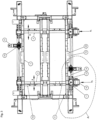
Fig. 3 shows a horizontal view (from above) andFig. 4 part (denoted A inFig. 3 ) of the equipment shown inFigs. 1 and2 with a mechanism for adjusting the end walls to adjust the size of themould cavity 5 and thereby the size of the cast ingot (the mechanism for flexing is excluded from this figure). Each of thelong side walls 3 are releasable fixed to theframe 2 at each end viabrackets 9, while theshort end walls 4 are provided on amovable beam 10 connected at each end to aholder 11 which is movably provided along aguide rail 12 on theframe 2. Thebeams 10 with theshort end walls 4 may be adjusted (moved in direction x as denoted in the figure) by means ofelectric motors 13 provided on each side of the mould via a gear (not further shown) with worm screw driving means 14, 15. Themotors 13 may preferably be controlled by a computer, and theshort end walls 4 thereby adjusted, in accordance with a preset dimension scheme with (such as) 50 mm dimension steps as indicated above, or be freely operated to a desired dimension. After being adjusted to the desired dimension, the short end walls are held in position between thelong side walls 3 by means of asecuring arrangement 16 provided on themovable beam 10. The securingarrangement 16 may be a mechanical device or piston/cylinder device, preferably apneumatic jack device 16 as shown inFig. 4 pressing with a pre set force against thelong side walls 3 from the outside in direction of the arrow Fy as shown in the figure. -
Fig. 5 shows a horizontal view of the equipment shown inFig. 1 and2 , including the mechanism (means) for flexing the moulds, but for clarity reason excluding the mechanism (means) for adjusting the size of the mould of the casting equipment as shown inFig. 3 .Fig. 6 shows in larger scale and in perspective part of the equipment inFig. 5 - Each of the
long side walls 3 for eachmould 7 are at their respective ends as stated above fixed to theframe 2 by means ofbrackets 9, but at their middle part attached to adjustingbeams 17 arranged in parallel with saidside walls 3. Thelong side walls 3 are attached to the beams via an adjustable stiffening arrangement 33 (further explained below). The adjusting beams 17 are of greater length than thelong side walls 3 and are each at their respective ends connected to pull/push bars 18, 19 via connectors in the form of friction grip clamping devices or the like 20 (not further shown). The pull/push bars are provided in parallel with the short end walls and are adapted for axial movement throughholders 21 with slide bearings (not shown as such) by means of anactuating mechanism 22. The actuating mechanism includes two lever arms, one 23 rotatably provided on the left hand side of the frame 2 (as shown in the figure) and another 24 rotatably provided on the right hand side of the frame and being linked to one another through alink arm 25, and an actuator such as a cylinder/piston device 26 connected with thelever arm 24 provided to rotate thelever arm 24 as well as thelever arm 23 via thelink arm 25. - The
lever arm 24 is directly connected to theactuator 26 via a link and the flexing of thelong side walls 3 of mould is obtained by moving the adjusting beams 17 outwardly from or inwardly towards the centre of themould 7 by means of the actuator through axial movement of the pull/push bars 18, 19, 25 via thelever arms long side walls 3 are thereby adjusted inwardly or outwardly to adapt to the desired sheet ingot. The transmission ratio of the actuating mechanism and thereby the flexing of the side walls, is defined by the length of the arms of thelevers - As stated above the
actuator 26 may suitably be in the form of hydraulic piston/cylinder device with an internal piston sensor, where the piston may be controlled by means of a PLC (Programmable Logic Control) via a servo valve (or proportional valve) on the basis of a predetermined pattern of flexing depending on the dimension of the sheet ingot to be cast, the alloy composition and the casting speed. - The stiffening
arrangement 33 in conjunction with the flexinglong side walls 3 represents an important feature of the invention and enables adjustment of the stiffness of the middle part of the long side walls in relation to the size of the dimension of the ingot to be cast. Thus, if the dimension of the ingot is increased, the stiffness of the middle part of the long wall needs to be increased over a larger part of the wall as well. The stiffness is calculated on the basis of suitable algorithm which is not further explained herein. The stiffeningarrangement 33 as such (design) is, however, further shown in details inFigs. 7 and8 . Hence,Fig 7 a) shows the flexiblelong side wall 3 with anintegrated stiffening part 32. The stiffeningpart 32 stretches over a length of the middle part of thelong side wall 3 on the outside of the wall (relative to the mould cavity) and has an elevated shape from its ends towards the middle (triangular shape). As is shown inFig. 7 b) , a stiffeningintermediate plate 28 is adapted to fit with the stiffeningpart 32 and is connected to the long side wall and stiffeningpart 32, as further shown inFigs. 7c ) andFig 8 , by means of through goingbolts 30.Fig. 8 shows in addition thelong side wall 3 and stiffeningarrangement 33 the adjusting beam 17 (described above) and which in turn is connected to thestiffening plate 28 by means of connectingbolts 31. The stiffness of the middle part of the long side walls can be increase or reduced by means of thebolts 30. If the two middle bolts are used, the stiffness is reduced. On the other hand if the outer bolts, one on each side, are used the stiffness increases over a larger length of the middle part of the long sides.3.
Claims (8)
- Equipment for the semi-continuous direct chill (DC) casting of sheet ingot or slabs of different dimensions, in particular for rolling purposes, including a mould frame (2) with a pair of facing long side walls (3) and a pair of facing short end walls (4), the walls defining an upwardly open inlet for the supply of metal and a downwardly facing outlet provided with a starter block (5) on a movable support which prior to each casting closes the opening and including means for changing the mould dimensions where at least one end wall can be displaced to enable casting of ingots with different sizes, the equipment further including means for indirect and direct cooling of the metal during casting,wherein the equipment, in addition to the means for changing the mould dimensions, includes means for flexing the long side walls (3) of the mould, thereby enabling adjustment of a flexible middle part of said long side walls (3) inwardly or outwardly to adapt to the desired sheet ingot size, the desired casting speed and/or alloy composition,wherein a stiffening arrangement (33) is provided in conjunction with the flexing long side walls (3) enabling adjustment of the stiffness of the middle part of the long side walls in relation to the size of the dimension of the ingot to be cast, and wherein the stiffening arrangement (33) consists of a flexible long side wall (3) with an integrated stiffening part (32) stretching over a length of the middle part of the long side wall (3) on the outside of the wall and having an elevated shape from its ends towards the middle.
- Equipment according to claim 1,
characterised in that
the short end walls (4) are each movably provided between the long side walls (3) on a beam (10). - Equipment according to claim 2,
characterised in that
each beam (10) are movably provided on the frame (2) along a guide (12) by means of a drive arrangement (13, 16). - Equipment according to claims 1 - 3,
characterised in that
the short end walls (4) for each mould dimension during casting are held in position between the long side walls (3) by means of a securing arrangement (16). - Equipment according to claim 4,
characterised in that
the securing arrangement (16) is a piston/cylinder device pressing against the long side walls (3) from the outside and towards the ends of the short end walls (4). - Equipment according to claim 5,
characterised in that
the piston/cylinder device is a pneumatic device. - Equipment according to claim 4,
characterised in that
the securing arrangement (16) is provided on the beam (10) and is movable with the beam. - Equipment according to claim 1 - 7,
characterised in that
it further includes a stiffening intermediate plate (28) adapted to fit with the stiffening part (32) and being connected to a long side wall (3) and stiffening part (32) by means of through going bolts (30).
Priority Applications (2)
| Application Number | Priority Date | Filing Date | Title |
|---|---|---|---|
| HRP20250578TT HRP20250578T1 (en) | 2008-11-21 | 2009-09-07 | Casting equipment for the casting of sheet ingot |
| SI200932212T SI2358488T1 (en) | 2008-11-21 | 2009-09-07 | Casting equipment for the casting of sheet ingot |
Applications Claiming Priority (2)
| Application Number | Priority Date | Filing Date | Title |
|---|---|---|---|
| NO20084917A NO347543B1 (en) | 2008-11-21 | 2008-11-21 | Støpeutstyr for støping av valseblokk |
| PCT/NO2009/000309 WO2010059058A1 (en) | 2008-11-21 | 2009-09-07 | Casting equipment for the casting of sheet ingot |
Publications (3)
| Publication Number | Publication Date |
|---|---|
| EP2358488A1 EP2358488A1 (en) | 2011-08-24 |
| EP2358488A4 EP2358488A4 (en) | 2018-04-04 |
| EP2358488B1 true EP2358488B1 (en) | 2025-04-16 |
Family
ID=42198327
Family Applications (1)
| Application Number | Title | Priority Date | Filing Date |
|---|---|---|---|
| EP09827793.2A Active EP2358488B1 (en) | 2008-11-21 | 2009-09-07 | Casting equipment for the casting of sheet ingot |
Country Status (13)
| Country | Link |
|---|---|
| US (1) | US8561669B2 (en) |
| EP (1) | EP2358488B1 (en) |
| CN (2) | CN104785736B (en) |
| CA (1) | CA2743498C (en) |
| ES (1) | ES3032484T3 (en) |
| HR (1) | HRP20250578T1 (en) |
| HU (1) | HUE071401T2 (en) |
| NO (1) | NO347543B1 (en) |
| PL (1) | PL2358488T3 (en) |
| PT (1) | PT2358488T (en) |
| RU (1) | RU2482937C2 (en) |
| SI (1) | SI2358488T1 (en) |
| WO (1) | WO2010059058A1 (en) |
Families Citing this family (12)
| Publication number | Priority date | Publication date | Assignee | Title |
|---|---|---|---|---|
| US8905119B2 (en) * | 2010-10-18 | 2014-12-09 | Norsk Hydro Asa | Casting equipment starter block |
| JP5944220B2 (en) * | 2012-04-27 | 2016-07-05 | スチールプランテック株式会社 | Mold clamp device and continuous casting equipment using the same |
| US11331715B2 (en) | 2017-06-12 | 2022-05-17 | Wagstaff, Inc. | Dynamic mold shape control for direct chill casting |
| US11883876B2 (en) | 2017-06-12 | 2024-01-30 | Wagstaff, Inc. | Dynamic mold shape control for direct chill casting |
| US10350674B2 (en) | 2017-06-12 | 2019-07-16 | Wagstaff, Inc. | Dynamic mold shape control for direct chill casting |
| NO345211B1 (en) * | 2018-09-10 | 2020-11-09 | Norsk Hydro As | Method to determining a presence or absence of water in a DC casting starter block and DC casting equipment |
| US10875087B1 (en) * | 2020-02-20 | 2020-12-29 | Wagstaff, Inc. | System, apparatus, and method for mold starter block alignment |
| KR20240138121A (en) | 2020-03-26 | 2024-09-20 | 노벨리스 인크. | Method of controlling the shape of an ingot head |
| CN113102698A (en) * | 2021-04-21 | 2021-07-13 | 重庆西南铝机电设备工程有限公司 | Aluminum alloy slab ingot dynamic deformation casting crystallization device |
| US11717882B1 (en) | 2022-02-18 | 2023-08-08 | Wagstaff, Inc. | Mold casting surface cooling |
| CN116274897A (en) * | 2023-03-07 | 2023-06-23 | 包头稀土研究院 | Rare earth metal ingot casting device |
| CN117399579A (en) * | 2023-11-07 | 2024-01-16 | 中铜华中铜业有限公司 | A copper and copper alloy crystallizer with adjustable width and thickness |
Family Cites Families (15)
| Publication number | Priority date | Publication date | Assignee | Title |
|---|---|---|---|---|
| CH508432A (en) * | 1970-03-25 | 1971-06-15 | Concast Ag | Adjustable plate mold for continuous casting |
| US4030536A (en) * | 1973-04-30 | 1977-06-21 | Alcan Research And Development Limited | Apparatus for continuous casting of metals |
| AT371388B (en) * | 1981-10-09 | 1983-06-27 | Voest Alpine Ag | PLATE CHOCOLATE FOR CONTINUOUS CASTING |
| CH658009A5 (en) * | 1982-02-12 | 1986-10-15 | Concast Service Union Ag | METHOD AND PLATE CHILL FOR COOLING AND SUPPORTING A STRAND IN A PLATE CHOCOLATE IN A STEEL MOLDING PLANT. |
| US4669526A (en) * | 1985-06-20 | 1987-06-02 | Sms Concast Inc. | Remotely adjustable continuous casting mold |
| US4660615A (en) * | 1986-03-14 | 1987-04-28 | Kabushiki Kaisha Kobe Seiko Sho | Continuous casting mold assembly |
| US5279354A (en) * | 1990-11-30 | 1994-01-18 | Acutus Industries, Inc. | Method of continuous casting with changing of slab width |
| NO302803B1 (en) * | 1996-03-20 | 1998-04-27 | Norsk Hydro As | Equipment for use in continuous casting of metal |
| EP0812638A1 (en) | 1996-06-14 | 1997-12-17 | Alusuisse Technology & Management AG | Adjustable continuous casting mould |
| JP3521667B2 (en) * | 1997-01-14 | 2004-04-19 | 日本軽金属株式会社 | Variable width casting machine for continuous casting of aluminum or its alloys |
| US6056040A (en) * | 1997-10-10 | 2000-05-02 | Alcan International Limited | Mould device with adjustable walls |
| RU2188388C2 (en) * | 1999-11-02 | 2002-08-27 | Российский Федеральный Ядерный Центр - Всероссийский Научно-Исследовательский Институт Экспериментальной Физики | Device for measurement of true parameters of inner surfaces and radii of spherical articles |
| JP2002137045A (en) | 2000-11-01 | 2002-05-14 | Nippon Light Metal Co Ltd | Variable width mold device |
| US6857464B2 (en) * | 2002-09-19 | 2005-02-22 | Hatch Associates Ltd. | Adjustable casting mold |
| DE102004021899A1 (en) * | 2004-05-04 | 2005-12-01 | Sms Demag Ag | Chilled continuous casting mold |
-
2008
- 2008-11-21 NO NO20084917A patent/NO347543B1/en unknown
-
2009
- 2009-09-07 HU HUE09827793A patent/HUE071401T2/en unknown
- 2009-09-07 PL PL09827793.2T patent/PL2358488T3/en unknown
- 2009-09-07 HR HRP20250578TT patent/HRP20250578T1/en unknown
- 2009-09-07 CN CN201510077111.7A patent/CN104785736B/en active Active
- 2009-09-07 RU RU2011125307/02A patent/RU2482937C2/en active
- 2009-09-07 CN CN2009801462151A patent/CN102223967A/en active Pending
- 2009-09-07 WO PCT/NO2009/000309 patent/WO2010059058A1/en not_active Ceased
- 2009-09-07 SI SI200932212T patent/SI2358488T1/en unknown
- 2009-09-07 EP EP09827793.2A patent/EP2358488B1/en active Active
- 2009-09-07 ES ES09827793T patent/ES3032484T3/en active Active
- 2009-09-07 CA CA2743498A patent/CA2743498C/en active Active
- 2009-09-07 PT PT98277932T patent/PT2358488T/en unknown
- 2009-09-07 US US13/128,291 patent/US8561669B2/en active Active
Also Published As
| Publication number | Publication date |
|---|---|
| SI2358488T1 (en) | 2025-07-31 |
| RU2011125307A (en) | 2012-12-27 |
| HUE071401T2 (en) | 2025-08-28 |
| US8561669B2 (en) | 2013-10-22 |
| PT2358488T (en) | 2025-06-05 |
| HRP20250578T1 (en) | 2025-07-04 |
| US20110315339A1 (en) | 2011-12-29 |
| CN102223967A (en) | 2011-10-19 |
| NO347543B1 (en) | 2023-12-27 |
| CN104785736B (en) | 2018-03-20 |
| NO20084917L (en) | 2010-05-25 |
| CN104785736A (en) | 2015-07-22 |
| EP2358488A4 (en) | 2018-04-04 |
| CA2743498A1 (en) | 2010-05-27 |
| PL2358488T3 (en) | 2025-08-18 |
| EP2358488A1 (en) | 2011-08-24 |
| WO2010059058A1 (en) | 2010-05-27 |
| ES3032484T3 (en) | 2025-07-21 |
| CA2743498C (en) | 2016-04-26 |
| RU2482937C2 (en) | 2013-05-27 |
Similar Documents
| Publication | Publication Date | Title |
|---|---|---|
| US8561669B2 (en) | Casting equipment for the casting of sheet ingot | |
| US7975752B2 (en) | Co-casting of metals by direct chill casting | |
| US11548061B2 (en) | Dynamic mold shape control for direct chill casting | |
| JP2024102068A (en) | Direct Chill Casting Mold System | |
| CA2200392C (en) | Equipment for continuous casting of metals | |
| EP2629908B1 (en) | Casting equipment starter block | |
| RU2289494C2 (en) | Regulated divider placed in standard chill mold for slabs | |
| JP2005095955A (en) | Method and apparatus for continuous casting of thin sheet of high thermal conductivity material | |
| JP4835804B2 (en) | Continuous casting mold, taper adjustment method and continuous casting method for continuous casting mold | |
| JP2794653B2 (en) | Driving device for nozzle stopper for casting | |
| CA3169621A1 (en) | Method of controlling the shape of an ingot head |
Legal Events
| Date | Code | Title | Description |
|---|---|---|---|
| REG | Reference to a national code |
Ref country code: HR Ref legal event code: TUEP Ref document number: P20250578T Country of ref document: HR |
|
| PUAI | Public reference made under article 153(3) epc to a published international application that has entered the european phase |
Free format text: ORIGINAL CODE: 0009012 |
|
| 17P | Request for examination filed |
Effective date: 20110621 |
|
| AK | Designated contracting states |
Kind code of ref document: A1 Designated state(s): AT BE BG CH CY CZ DE DK EE ES FI FR GB GR HR HU IE IS IT LI LT LU LV MC MK MT NL NO PL PT RO SE SI SK SM TR |
|
| DAX | Request for extension of the european patent (deleted) | ||
| RIC1 | Information provided on ipc code assigned before grant |
Ipc: B22D 11/05 20060101AFI20170921BHEP |
|
| RA4 | Supplementary search report drawn up and despatched (corrected) |
Effective date: 20180306 |
|
| RIC1 | Information provided on ipc code assigned before grant |
Ipc: B22D 11/05 20060101AFI20180228BHEP |
|
| STAA | Information on the status of an ep patent application or granted ep patent |
Free format text: STATUS: EXAMINATION IS IN PROGRESS |
|
| 17Q | First examination report despatched |
Effective date: 20190621 |
|
| P01 | Opt-out of the competence of the unified patent court (upc) registered |
Effective date: 20230607 |
|
| GRAP | Despatch of communication of intention to grant a patent |
Free format text: ORIGINAL CODE: EPIDOSNIGR1 |
|
| STAA | Information on the status of an ep patent application or granted ep patent |
Free format text: STATUS: GRANT OF PATENT IS INTENDED |
|
| GRAS | Grant fee paid |
Free format text: ORIGINAL CODE: EPIDOSNIGR3 |
|
| GRAA | (expected) grant |
Free format text: ORIGINAL CODE: 0009210 |
|
| STAA | Information on the status of an ep patent application or granted ep patent |
Free format text: STATUS: THE PATENT HAS BEEN GRANTED |
|
| INTG | Intention to grant announced |
Effective date: 20250212 |
|
| AK | Designated contracting states |
Kind code of ref document: B1 Designated state(s): AT BE BG CH CY CZ DE DK EE ES FI FR GB GR HR HU IE IS IT LI LT LU LV MC MK MT NL NO PL PT RO SE SI SK SM TR |
|
| REG | Reference to a national code |
Ref country code: GB Ref legal event code: FG4D |
|
| REG | Reference to a national code |
Ref country code: CH Ref legal event code: EP Ref country code: DE Ref legal event code: R096 Ref document number: 602009065501 Country of ref document: DE |
|
| REG | Reference to a national code |
Ref country code: IE Ref legal event code: FG4D |
|
| REG | Reference to a national code |
Ref country code: NL Ref legal event code: FP |
|
| REG | Reference to a national code |
Ref country code: PT Ref legal event code: SC4A Ref document number: 2358488 Country of ref document: PT Date of ref document: 20250605 Kind code of ref document: T Free format text: AVAILABILITY OF NATIONAL TRANSLATION Effective date: 20250530 |
|
| REG | Reference to a national code |
Ref country code: HR Ref legal event code: T1PR Ref document number: P20250578 Country of ref document: HR |
|
| REG | Reference to a national code |
Ref country code: ES Ref legal event code: FG2A Ref document number: 3032484 Country of ref document: ES Kind code of ref document: T3 Effective date: 20250721 |
|
| REG | Reference to a national code |
Ref country code: GR Ref legal event code: EP Ref document number: 20250401100 Country of ref document: GR Effective date: 20250707 |
|
| REG | Reference to a national code |
Ref country code: HU Ref legal event code: AG4A Ref document number: E071401 Country of ref document: HU |
|
| REG | Reference to a national code |
Ref country code: HR Ref legal event code: ODRP Ref document number: P20250578 Country of ref document: HR Payment date: 20250829 Year of fee payment: 17 |
|
| REG | Reference to a national code |
Ref country code: CH Ref legal event code: U11 Free format text: ST27 STATUS EVENT CODE: U-0-0-U10-U11 (AS PROVIDED BY THE NATIONAL OFFICE) Effective date: 20251001 |
|
| PG25 | Lapsed in a contracting state [announced via postgrant information from national office to epo] |
Ref country code: FI Free format text: LAPSE BECAUSE OF FAILURE TO SUBMIT A TRANSLATION OF THE DESCRIPTION OR TO PAY THE FEE WITHIN THE PRESCRIBED TIME-LIMIT Effective date: 20250416 |
|
| PGFP | Annual fee paid to national office [announced via postgrant information from national office to epo] |
Ref country code: PT Payment date: 20250828 Year of fee payment: 17 |
|
| PGFP | Annual fee paid to national office [announced via postgrant information from national office to epo] |
Ref country code: DE Payment date: 20250919 Year of fee payment: 17 |
|
| REG | Reference to a national code |
Ref country code: LT Ref legal event code: MG9D |
|
| PGFP | Annual fee paid to national office [announced via postgrant information from national office to epo] |
Ref country code: NO Payment date: 20250923 Year of fee payment: 17 Ref country code: GR Payment date: 20250922 Year of fee payment: 17 |
|
| PGFP | Annual fee paid to national office [announced via postgrant information from national office to epo] |
Ref country code: PL Payment date: 20250828 Year of fee payment: 17 Ref country code: IT Payment date: 20250923 Year of fee payment: 17 Ref country code: NL Payment date: 20250918 Year of fee payment: 17 Ref country code: TR Payment date: 20250901 Year of fee payment: 17 |
|
| PG25 | Lapsed in a contracting state [announced via postgrant information from national office to epo] |
Ref country code: BG Free format text: LAPSE BECAUSE OF FAILURE TO SUBMIT A TRANSLATION OF THE DESCRIPTION OR TO PAY THE FEE WITHIN THE PRESCRIBED TIME-LIMIT Effective date: 20250416 |
|
| PGFP | Annual fee paid to national office [announced via postgrant information from national office to epo] |
Ref country code: HU Payment date: 20250922 Year of fee payment: 17 Ref country code: BE Payment date: 20250918 Year of fee payment: 17 Ref country code: GB Payment date: 20250918 Year of fee payment: 17 |
|
| PGFP | Annual fee paid to national office [announced via postgrant information from national office to epo] |
Ref country code: HR Payment date: 20250829 Year of fee payment: 17 |
|
| PGFP | Annual fee paid to national office [announced via postgrant information from national office to epo] |
Ref country code: FR Payment date: 20250922 Year of fee payment: 17 Ref country code: AT Payment date: 20250919 Year of fee payment: 17 |
|
| PGFP | Annual fee paid to national office [announced via postgrant information from national office to epo] |
Ref country code: CZ Payment date: 20250903 Year of fee payment: 17 |
|
| PGFP | Annual fee paid to national office [announced via postgrant information from national office to epo] |
Ref country code: IS Payment date: 20250911 Year of fee payment: 17 |
|
| PG25 | Lapsed in a contracting state [announced via postgrant information from national office to epo] |
Ref country code: LV Free format text: LAPSE BECAUSE OF FAILURE TO SUBMIT A TRANSLATION OF THE DESCRIPTION OR TO PAY THE FEE WITHIN THE PRESCRIBED TIME-LIMIT Effective date: 20250416 |
|
| PGFP | Annual fee paid to national office [announced via postgrant information from national office to epo] |
Ref country code: SI Payment date: 20250828 Year of fee payment: 17 |
|
| PG25 | Lapsed in a contracting state [announced via postgrant information from national office to epo] |
Ref country code: DK Free format text: LAPSE BECAUSE OF FAILURE TO SUBMIT A TRANSLATION OF THE DESCRIPTION OR TO PAY THE FEE WITHIN THE PRESCRIBED TIME-LIMIT Effective date: 20250416 Ref country code: SM Free format text: LAPSE BECAUSE OF FAILURE TO SUBMIT A TRANSLATION OF THE DESCRIPTION OR TO PAY THE FEE WITHIN THE PRESCRIBED TIME-LIMIT Effective date: 20250416 |
|
| PGFP | Annual fee paid to national office [announced via postgrant information from national office to epo] |
Ref country code: CH Payment date: 20251001 Year of fee payment: 17 |
|
| REG | Reference to a national code |
Ref country code: DE Ref legal event code: R097 Ref document number: 602009065501 Country of ref document: DE |
|
| PG25 | Lapsed in a contracting state [announced via postgrant information from national office to epo] |
Ref country code: EE Free format text: LAPSE BECAUSE OF FAILURE TO SUBMIT A TRANSLATION OF THE DESCRIPTION OR TO PAY THE FEE WITHIN THE PRESCRIBED TIME-LIMIT Effective date: 20250416 |
|
| PG25 | Lapsed in a contracting state [announced via postgrant information from national office to epo] |
Ref country code: RO Free format text: LAPSE BECAUSE OF FAILURE TO SUBMIT A TRANSLATION OF THE DESCRIPTION OR TO PAY THE FEE WITHIN THE PRESCRIBED TIME-LIMIT Effective date: 20250416 Ref country code: SK Free format text: LAPSE BECAUSE OF FAILURE TO SUBMIT A TRANSLATION OF THE DESCRIPTION OR TO PAY THE FEE WITHIN THE PRESCRIBED TIME-LIMIT Effective date: 20250416 |
|
| PGFP | Annual fee paid to national office [announced via postgrant information from national office to epo] |
Ref country code: ES Payment date: 20251028 Year of fee payment: 17 |
|
| PLBE | No opposition filed within time limit |
Free format text: ORIGINAL CODE: 0009261 |
|
| STAA | Information on the status of an ep patent application or granted ep patent |
Free format text: STATUS: NO OPPOSITION FILED WITHIN TIME LIMIT |
|
| REG | Reference to a national code |
Ref country code: CH Ref legal event code: L10 Free format text: ST27 STATUS EVENT CODE: U-0-0-L10-L00 (AS PROVIDED BY THE NATIONAL OFFICE) Effective date: 20260225 |
|
| 26N | No opposition filed |
Effective date: 20260119 |