EP2357791A1 - Drive control apparatus, image pickup apparatus, and drive control method - Google Patents
Drive control apparatus, image pickup apparatus, and drive control method Download PDFInfo
- Publication number
- EP2357791A1 EP2357791A1 EP10194727A EP10194727A EP2357791A1 EP 2357791 A1 EP2357791 A1 EP 2357791A1 EP 10194727 A EP10194727 A EP 10194727A EP 10194727 A EP10194727 A EP 10194727A EP 2357791 A1 EP2357791 A1 EP 2357791A1
- Authority
- EP
- European Patent Office
- Prior art keywords
- drive
- stepping motor
- phase
- micro
- focus lens
- Prior art date
- Legal status (The legal status is an assumption and is not a legal conclusion. Google has not performed a legal analysis and makes no representation as to the accuracy of the status listed.)
- Granted
Links
- 238000000034 method Methods 0.000 title claims description 51
- 230000005284 excitation Effects 0.000 claims abstract description 24
- 230000007246 mechanism Effects 0.000 claims abstract description 10
- 230000005540 biological transmission Effects 0.000 claims abstract description 9
- 230000033001 locomotion Effects 0.000 claims description 35
- 238000012937 correction Methods 0.000 claims description 34
- 230000008569 process Effects 0.000 description 31
- 238000011156 evaluation Methods 0.000 description 23
- 230000003287 optical effect Effects 0.000 description 12
- 238000010586 diagram Methods 0.000 description 7
- 238000012545 processing Methods 0.000 description 5
- 230000004907 flux Effects 0.000 description 4
- 230000008859 change Effects 0.000 description 2
- 230000006866 deterioration Effects 0.000 description 2
- 230000010355 oscillation Effects 0.000 description 2
- 238000006243 chemical reaction Methods 0.000 description 1
- 238000001514 detection method Methods 0.000 description 1
- 239000000284 extract Substances 0.000 description 1
- 238000003384 imaging method Methods 0.000 description 1
- 238000012986 modification Methods 0.000 description 1
- 230000004048 modification Effects 0.000 description 1
- 239000004065 semiconductor Substances 0.000 description 1
- 230000003068 static effect Effects 0.000 description 1
Images




Classifications
-
- H—ELECTRICITY
- H04—ELECTRIC COMMUNICATION TECHNIQUE
- H04N—PICTORIAL COMMUNICATION, e.g. TELEVISION
- H04N23/00—Cameras or camera modules comprising electronic image sensors; Control thereof
- H04N23/60—Control of cameras or camera modules
- H04N23/67—Focus control based on electronic image sensor signals
- H04N23/672—Focus control based on electronic image sensor signals based on the phase difference signals
-
- G—PHYSICS
- G02—OPTICS
- G02B—OPTICAL ELEMENTS, SYSTEMS OR APPARATUS
- G02B7/00—Mountings, adjusting means, or light-tight connections, for optical elements
- G02B7/02—Mountings, adjusting means, or light-tight connections, for optical elements for lenses
- G02B7/04—Mountings, adjusting means, or light-tight connections, for optical elements for lenses with mechanism for focusing or varying magnification
- G02B7/08—Mountings, adjusting means, or light-tight connections, for optical elements for lenses with mechanism for focusing or varying magnification adapted to co-operate with a remote control mechanism
-
- H—ELECTRICITY
- H02—GENERATION; CONVERSION OR DISTRIBUTION OF ELECTRIC POWER
- H02P—CONTROL OR REGULATION OF ELECTRIC MOTORS, ELECTRIC GENERATORS OR DYNAMO-ELECTRIC CONVERTERS; CONTROLLING TRANSFORMERS, REACTORS OR CHOKE COILS
- H02P8/00—Arrangements for controlling dynamo-electric motors rotating step by step
- H02P8/22—Control of step size; Intermediate stepping, e.g. microstepping
Definitions
- the present invention relates to a drive control apparatus, an image pickup apparatus, and a drive control method, and more particularly to a technology of performing a micro step drive of a stepping motor.
- a stepping motor is widely adopted as a mechanism for driving a focus lens or a zoom lens.
- a rotation power of the stepping motor is transmitted to the lens via a transmission mechanism constituted of a screw shaft and a rack engaging with it, and it becomes a power source of the lens in an optical axis direction.
- a TV-AF method In an AF (autofocus) control of the video camera or the digital camera, a TV-AF method is widely adopted.
- the TV-AF method detects a signal obtained by extracting a high frequency component in a predetermined range of a taken image as an AF evaluation value to control a movement of the focus lens so that the AF evaluation value is maximized.
- a repeating motion of a minute movement in both directions of a telephoto side and a wide angle side of the focus lens hereinafter, referred to as a "wobbling" is repeated to detect a position of the focus lens where the AF evaluation value is maximized.
- micro step drive method uses an excitation current having a sinusoidal waveform to realize a drive with steps (micro steps) in which one step (the minimum rotation angle) of the stepping motor is finer.
- the rotation angle in each micro step varies in accordance with a phase of the excitation current (hereinafter, referred to as a "step phase").
- the cause of the variation is that a magnetic attractive force pulsates by a bias of a magnetic flux distribution of a permanent magnet that is a rotor of the stepping motor (hereinafter, referred to as "cogging").
- the variation of the rotation angle in each step phase by the cogging causes the variation of movement amplitude of the focus lens at the time of the wobbling operation. As a result, a problem described below may be generated.
- a wobbling width (the number of driven micros steps) is determined on the basis of a step phase where a rotation angle is small
- an amount of movement of the focus lens may be equal to or larger than a depth of field in the wobbling operation in a step phase where the rotation angle is large. This causes a float of an in-focus state.
- the wobbling width is determined on the basis of a step phase where the rotation angle is large, a so-called step-out may be generated since kinetic energy for a minute movement of the focus lens cannot be obtained in the wobbling operation in the step phase where the rotation angle is small.
- Japanese Patent Laid-Open No. 01-218393 proposes a correction of a waveform of an excitation current referring to a correction table so that a rotation angle in each step phase becomes constant.
- the proposal in Japanese Patent Laid-Open No. 01-218393 is not necessarily suitable for the image pickup apparatus such as a video camera or a digital camera.
- a bias of a magnetic flux distribution of a permanent magnet has a strong temperature dependency, but a static correction using a correction table effectively functions only at a specific temperature. Therefore, it is not suitable for the video camera or the digital camera that is used in an environment which dynamically changes.
- a waveform of an excitation current When a waveform of an excitation current is corrected, it causes the generation of a motor vibration sound at the time of inversing a rotation direction in a control which reverses the wobbling such as an AF control because a phase difference between stop positions in a positive direction and an inverse direction is generated.
- the proposal in Japanese Patent Laid-Open No. 01-218393 is not suitable for the video camera or the digital camera that stores a voice.
- the present invention eases a problem caused by a variation of the rotation angle of the stepping motor in each micro step in accordance with a step phase.
- the present invention in its first aspect provides a drive control apparatus as specified in claims 1 and 2.
- the present invention in its second aspect provides an image pickup apparatus as specified in claim 3.
- the present invention in its third aspect provides a drive control method as specified in claims 4 and 5.
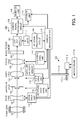
- Fig. 1 is a block diagram illustrating a configuration of an image pickup apparatus 100 in a first embodiment.
- Fig. 2 is a conceptual diagram of a TV-AF method.
- Fig. 3 is a flowchart illustrating the TV-AF method in the first embodiment.
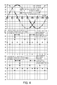
- Fig. 4 is a conceptual diagram illustrating a state in which a rotation angle of each micro step of a stepping motor varies in accordance with a step phase.
- Fig. 5 is a flowchart illustrating details of processes in Steps S310 and S316 of Fig. 3 in accordance with the first embodiment.
- Figs. 6A to 6D are conceptual diagrams illustrating a movement width of a focus lens after the number of micro steps in a wobbling operation is corrected.
- Fig. 7 is a flowchart illustrating details of processes in Steps S310 and S316 of Fig. 3 in accordance with a second embodiment.
- Fig. 1 is a block diagram illustrating a configuration of an image pickup apparatus 100 in a first embodiment.
- an image pickup optical system an imaging lens of the image pickup apparatus 100 includes a fixed lens 101, a zoom lens 102 that moves in an optical axis direction to perform zoom operation, and an aperture stop 103.
- the image pickup optical system also includes a shift lens 104 that moves in a direction perpendicular to an optical axis to deflect the optical axis to compensate the motion of an image caused by a shake.
- the image pickup apparatus 100 includes an angular velocity sensor 117 as a shake detector.
- the image pickup optical system includes a focus compensator lens (hereinafter, referred to as a "focus lens”) that has a function of correcting a movement of a focal plane caused by the zoom operation and a function of focusing operation.
- the image pickup optical system is integrally configured, but it may also be detachable.
- a control signal generated by a camera microcomputer 118 described below is communicated with a lens computer in the image pickup optical system to control the drive of the focus lens via the lens computer.
- the image pickup apparatus 100 also includes an image pickup element 106 as a photoelectric conversion element which is configured by a CCD sensor or a CMOS sensor, and a CDS/AGC circuit 107 which samples an output of the image pickup element 106 to perform a gain adjustment.
- an image pickup element 106 as a photoelectric conversion element which is configured by a CCD sensor or a CMOS sensor
- CDS/AGC circuit 107 which samples an output of the image pickup element 106 to perform a gain adjustment.
- a camera signal processing circuit 108 performs each kind of image processings for an output signal from the CDS/AGC circuit 107 to generate a video signal.
- a monitor unit 109 is constituted of a LCD or the like, and displays the video signal from the camera signal processing circuit 108.
- a storage unit 110 stores the video signal from the camera signal processing circuit 108 in a storage media such as a semiconductor memeory.
- a focusing drive unit 111, a shift drive unit 112, a zoom drive unit 113, and an aperture stop drive unit 114 drives the focus lens 105, the shift lens 104, the zoom lens 102, and the aperture stop 103, respectively.
- the focusing drive unit 111 includes a stepping motor 111-a and a motor driver 111-b (including a screw shaft (a feed screw) 111-c).
- the screw shaft 111-c engages with a rack 111-d which is provided on the focus lens 105.
- a power of the stepping motor 111-a (an energy generated by the drive) is transmitted as a power that moves the focus lens 105 via the screw shaft 111-c and the rack 111-d engaging with it, both of which function as a transmission mechanism.
- the other drive units are also constituted as similarly to the focusing drive unit 111.
- An AF gate 115 only passes a signal in a range that is used for focus detection of output signals of all pixels from the CDS/AGC circuit 107.
- An AF signal processing circuit 116 extracts a highfrequency component, a luminance difference component (a difference between the maximum value and the minimum value of a luminance level of a signal that passes through the AF gate 115), or the like from the signal that passes through the AF gate 115 to generate an AF evaluation value signal.
- the AF evaluation value signal represents sharpness (a contrast state) of a video that is generated based on the output signal from the image pickup element 106, but the sharpness is changed in accordance with an in-focus state of the image pickup optical system, and therefore as a result it is a signal that represents the in-focus state of the image pickup optical system.
- the camera microcomputer 118 controls the movements of the zoom lens 102, the shift lens 104, and the focus lens 105, and the opening and closing of the aperture stop 103.
- a drive control of the stepping motor in the present embodiment will be described using a case of an autofocus control which is performed by the camera microcomputer 118 (a drive control unit) and a focusing drive unit 111 as an example.
- a focus control by a TV-AF method hereafter, referred to as a "TV-AF"
- TV-AF TV-AF
- the focus lens 105 is moved so that the AF evaluation value becomes the maximum value while the focus lens is being wobbled to be able to focus on an object.
- Fig. 2 is a conceptual diagram of the TV-AF.
- a horizontal axis indicates a time in which a vertical synchronization signal of the image pickup element 106 is a unit time.
- a vertical axis indicates a position of the focus lens 105.
- Reference symbol "Mode” indicates a phase of the process at the time of performing the TV-AF. The following is a specific description.
- 'Mode 1: The focus lens 105 is moved from a close side to the infinite side in the wobbling. At this time, a center of the wobbling is also moved to the infinite side in some cases.
- 'Mode 2: The AF evaluation value (the close side evaluation value) based on electric charges accumulated in the image pickup element 106 when Mode is previously equal to 0 (at this time, the focus lens 105 is positioned at the close side in the wobbling) is obtained.
- the focus lens 105 is moved from the infinite side to the close side as a common wobbling operation, and is also moved to the closer side in order to move the center of the wobbling to the close side.
- the focus lens 105 moves from the close side to the infinite side as a common wobbling operation, but the center of the wobbling does not move. Repeating such operations, a position of the focus lens 105 where the AF evaluation value is peaked is detected.
- Fig. 3 is a flowchart illustrating the TV-AF in the first embodiment.
- the process of each step in the flowchart is realized by the camera microcomputer 118 performing a control program.
- the process in each Mode starts in synchronization with a vertical synchronization signal.
- Step S301 the camera microcomputer 118 determines whether a current Mode is 0. If the current Mode is 0, the process proceeds to Step S302. On the other hand, if not, the process proceeds to Step S306. In Step S302, the camera microcomputer 118 obtains the AF evaluation value at the infinite side. The AF evaluation value is based on the electric charges accumulated in the image pickup element 106 when Mode is previously equal to 2 (in this time, the focus lens 105 is positioned at the infinite side in the wobbling operation).
- Step S303, S304, and S305 the camera microcomputer 118 periodically changes "Mode” like 0, 1, 2, 3, 0, 1, 2, .... • Then, the process returns to Step S301.
- Step S306 the camera microcomputer 118 determines whether the current Mode is 1. If the current Mode is 1, the process proceeds to Step S307. On the other hand, if not, the process proceeds to Step S311. In Step S307, the camera microcomputer 118 determines whether the infinite side evaluation value obtained in Step S302 is greater than the close side evaluation value obtained when Mode is previously equal to 2 (Step S311 described below). If the value is greater, the process proceeds to Step S308. On the other hand, if not, the process proceeds to Step S309. When the close side evaluation value is not obtained, the process also proceeds to Step S309.
- Step S308 the camera microcomputer 118 sets a drive amplitude so as to be equal to a sum of a wobbling amplitude and a center moving amplitude, i.e. it increases an amount of movement to the infinite side to realize a movement of the center of the wobbling operation to the infinite side.
- the wobbling amplitude and the center moving amplitude may also be a fixed value which is previously set.
- Step S309 the camera microcomputer 118 sets the drive amplitude so as to be equal to the wobbling oscillation amplitude.
- the drive amplitude corresponds to the number of driven micro steps.
- Step S310 the camera microcomputer 118 controls the motor driver 111-b of the focusing drive unit 111 so as to generate an excitation waveform for performing the wobbling operation (details will be described below with reference to Fig. 5 ).
- Step S311 the camera microcomputer 118 determines whether the current Mode is 2. If the current Mode is 2, the process proceeds to Step S312. On the other hand, if not, the process proceeds to Step S313.
- Step S312 the camera microcomputer 118 obtains the AF evaluation value at the close side. The AF evaluation value is based on electric charges accumulated in the image pickup element 106 when Mode is previously equal to 0, i.e. the focus lens 105 is positioned at the close side in the wobbling operation.
- Step S313 the camera microcomputer 118 determines whether the close side evaluation value obtained in Step S312 is greater than the infinite side evaluation value obtained when Mode is previously equal to 0 (in Step S302 described above). If the value obtained in Step S312 is greater, the process proceeds to Step S314. On the other hand, if not, the process proceeds to Step S315.
- Step S314 the camera microcomputer 118 sets the drive amplitude so as to be equal to a sum of the wobbling amplitude and the center moving amplitude, i.e. it increases an amount of a movement to the close side to realize a movement of the center of the wobbling operation to the close side.
- Step S315 the camera microcomputer 118 sets the drive amplitude so as to be equal to the wobbling oscillation amplitude.
- Step S316 the camera microcomputer 118 controls the motor driver 111-b of the focusing drive unit 111 so as to generate an excitation waveform for performing the wobbling operation (details will be described below with reference to Fig. 5 ).
- Fig. 4 is a conceptual diagram illustrating a state in which a rotation angle of each micro step of the stepping motor varies in accordance with a step phase.
- the excitation of the stepping motor is performed by two phases of an A-phase and a B-phase.
- An excitation current of each phase has a sinusoidal waveform, and a phase difference between the A-phase and the B-phase is 90 degrees (when one period is expressed as 360 degrees).
- the phase of the excitation current is minimally changed to be able to perform a micro step drive in which one step of the stepping motor is divided into steps of a predetermined number (a micro step drive having a predetermined division number).
- a horizontal axis indicates a step phase (an excitation angle), and a vertical axis indicates an excitation current.
- one period is divided into 16 steps.
- a drive control which repeats the movement of the step phase centered around each step phase is performed.
- the change of the excitation waveform when the wobbling amplitude is set to ⁇ 1 step is illustrated.
- the state of the change of the excitation waveform in the wobbling operation in each step phase is different from each other.
- a rotation angle after the rotation of 1 step from each phase in each phase is different from each other. This is caused by cogging.
- a movement width of the focus lens 105 in a close and finite direction when the stepping motor 111-a performs the wobbling operation with an amplitude of two steps from each step phase is illustrated.
- a horizontal axis indicates a step phase (an excitation angle)
- a vertical axis indicates a movement width of the focus lens 105, which is represented by [%] regarding an ideal movement width as 100%.
- the movement width does not reach 100% because of a loss of the momentum which is generated in the transmission mechanism (the screw shaft 111-c and the rack 111-d) and a variation of the rotation angle of the stepping motor 111-a.
- a lens movement amount is small in the wobbling operation crossing a phase where the rotation angle of the stepping motor is small (a second phase).
- the lens movement amount is large in the wobbling operation crossing a phase where the rotation angle is large (a first phase).
- Fig. 5 is a flowchart illustrating details of the processes of Steps S310 and S316 in Fig. 3 .
- Step S501 the camera microcomputer 118 sets the current step phase (the excitation phase) to a variable n.
- Step S502 the camera microcomputer 118 determines whether the current Mode is 1. If the current Mode is 1, the process proceeds to Step S503. On the other hand, if not, i.e. if Mode is equal to 3, the process proceeds to Step S511.
- Step S503 or S511 the camera microcomputer 118 sets a value obtained by adding a correction (n) in the infinite or close direction to the drive amplitude (the number of micro steps) determined in Step S308, S309, S314, or S315 of Fig.
- the correction (n) is a correction value prepared for each phase n, which is for example stored in a ROM (not shown) of the camera microcomputer 118 as a table.
- the correction value is a value that is determined so that the variation of the movement amount of the focus lens in the wobbling operation from each step phase is reduced.
- the correction (n) is set so that an amount of the correction is large in the wobbling operation crossing a phase where the rotation angle of the stepping motor is small and the amount of the correction is small in the wobbling operation crossing a phase where the rotation angle is large.
- a correction table is defined as follows. Step phase
- Step S507 the camera microcomputer 118 drives the stepping motor 111-a in accordance with an excitation pattern of the A phase and the B phase corresponding to the step phase n that is the movement target.
- Step S508 the camera microcomputer 118 decrements the variable m.
- Step S509 the camera microcomputer 118 waits for a predetermined time in order to keep a rotation velocity of the stepping motor 111-a constant.
- the movement width of the focus lens 105 described with reference to Fig. 4 is corrected so as to be illustrated in Fig. 6A in the wobbling operation in the close direction, and Fig. 6B in the wobbling operation in the infinite direction. Because the correction is performed so that the movement width in a phase where the movement width is small increases, the focus lens 105 sufficiently moves in the wobbling operation. If the division number of the excitation waveform is increased to perform a finer micro step drive, "the variation of the movement width" can be further suppressed. For example, when the division number is set to 32, the correction table is defined as follows. Step phase
- the movement width of the focus lens 105 in this case is corrected as illustrated in Fig. 6C in the wobbling operation in the close direction, and in Fig. 6D in the wobbling operation in the infinite direction.
- the camera microcomputer 118 corrects the number of the micro steps corresponding to the movement width of the focus lens 105 at the time of the wobbling operation in accordance with the step phase.
- the focus lens 105 is sufficiently moved at the time of the wobbling operation.
- the method of the present embodiment does not induce the deterioration of the vibration of the stepping motor, it is suitably used for an image pickup apparatus provided with a microphone that inputs voice.
- an autofocus control using the focus lens 105 and the focusing drive unit 111 is described as an example, and the drive control of the stepping motor described above can also be applied to other usages.
- the drive control of the present embodiment can also be applied to a minute movement of the shift lens 104 in a direction perpendicular to the optical axis, which is performed to correct a shake.
- an auto blanket function that is widely provided in an image pickup apparatus such as a video camera or a digital camera
- a minute adjustment of an opening degree of the aperture stop is continuously performed.
- a fine exposure correction can be effectively performed.
- the number of the micro steps for the drive at the time of the wobbling operation is corrected in accordance with the step phase in the first embodiment.
- a rotation velocity of the stepping motor is corrected in accordance with the step phase in a second embodiment.
- a process illustrated in Fig. 7 is performed instead of the process illustrated in Fig. 5 .
- processes that are different from those of the first embodiment will be described.
- Step S701 the camera microcomputer 118 sets the drive amplitude (the number of the micro steps) which is determined in Step S308, S309, S314, or S315 of Fig. 3 to the variable m.
- the correction of the variable m is not performed (see Steps S503 and S511 in Fig. 5 ).
- the camera microcomputer 118 sets a value obtained by dividing a reference period of a wait period by a correction (n) in the infinite or close direction to a variable t.
- the correction (n) is a correction value prepared for each phase n, which is for example stored in a ROM (not shown) of the camera microcomputer 118 as a table.
- the correction value is a value that is determined so that the rotation velocity in a phase where the rotation angle is large is increased, i.e. the wait period is shortened.
- the correction (n) is set so that an amount of the correction is large in the wobbling operation crossing a phase where the rotation angle of the stepping motor is small and the amount of the correction is small in the wobbling operation crossing a phase where the rotation angle is large.
- a correction table is defined as follows. Step phase
- Step S704 the camera microcomputer 118 waits for the period indicated by the variable t.
- the variable t is, as described above, selected so that the wait period for each of the step phases "1, 5, 9, 13" in the wobbling operation in the close direction and "3, 7, 11, 15" in the wobbling operation in the infinite direction becomes half of the reference period. Accordingly, the rotation velocity of the stepping motor 111-a is twice as high as the normal rotation velocity. Thus, kinetic energy needed for the movement of the focus lens 105 is ensured.
- the camera microcomputer 118 corrects the rotation velocity of the stepping motor 111-a at the time of the wobbling operation in accordance with the step phase.
- the focus lens 105 is sufficiently moved at the wobbling operation.
- the method of the present embodiment does not induce the deterioration of the vibration of the stepping motor, it is suitably used for an image pickup apparatus provided with a microphone that inputs voice.
- the present invention is also realized by performing the following process.
- a software (a program) which realizes the function of each of the above embodiments is provided to a system or an apparatus via a network or each kind of storage media, and a computer (or a CPU, a MPU, or the like) of the system or the apparatus reads the program.
- a drive control apparatus (118) includes a stepping motor (111-a) capable of performing a micro step drive having a predetermined division number by using a sinusoidal excitation current, a transmission mechanism (111-c, 111-d) configured to transmit an energy generated by a drive of the stepping motor to a focus lens (105) to move the focus lens (105), and a controller (111-b) configured to control the stepping motor (111-a) so that the number of micro steps in a micro step drive having the predetermined division number in a drive crossing a first phase is smaller than the number of micro steps in a drive crossing a second phase where a rotation angle of the stepping motor (111-a) is smaller than a rotation angle in the first phase.
Landscapes
- Engineering & Computer Science (AREA)
- Multimedia (AREA)
- Signal Processing (AREA)
- Physics & Mathematics (AREA)
- Power Engineering (AREA)
- General Physics & Mathematics (AREA)
- Optics & Photonics (AREA)
- Automatic Focus Adjustment (AREA)
- Control Of Stepping Motors (AREA)
- Lens Barrels (AREA)
- Studio Devices (AREA)
Abstract
Description
- The present invention relates to a drive control apparatus, an image pickup apparatus, and a drive control method, and more particularly to a technology of performing a micro step drive of a stepping motor.
- In an image pickup apparatus such as a video camera or a digital camera, a stepping motor is widely adopted as a mechanism for driving a focus lens or a zoom lens. A rotation power of the stepping motor is transmitted to the lens via a transmission mechanism constituted of a screw shaft and a rack engaging with it, and it becomes a power source of the lens in an optical axis direction.
- In an AF (autofocus) control of the video camera or the digital camera, a TV-AF method is widely adopted. The TV-AF method detects a signal obtained by extracting a high frequency component in a predetermined range of a taken image as an AF evaluation value to control a movement of the focus lens so that the AF evaluation value is maximized. In the TV-AF method, a repeating motion of a minute movement in both directions of a telephoto side and a wide angle side of the focus lens (hereinafter, referred to as a "wobbling") is repeated to detect a position of the focus lens where the AF evaluation value is maximized.
- As a drive method of the stepping motor for the AF control of the TV-AF method, a micro step drive method is widely adopted. The micro step drive method uses an excitation current having a sinusoidal waveform to realize a drive with steps (micro steps) in which one step (the minimum rotation angle) of the stepping motor is finer.
- However, in the micro step drive method, the rotation angle in each micro step varies in accordance with a phase of the excitation current (hereinafter, referred to as a "step phase"). The cause of the variation is that a magnetic attractive force pulsates by a bias of a magnetic flux distribution of a permanent magnet that is a rotor of the stepping motor (hereinafter, referred to as "cogging"). The variation of the rotation angle in each step phase by the cogging causes the variation of movement amplitude of the focus lens at the time of the wobbling operation. As a result, a problem described below may be generated.
- When a wobbling width (the number of driven micros steps) is determined on the basis of a step phase where a rotation angle is small, an amount of movement of the focus lens may be equal to or larger than a depth of field in the wobbling operation in a step phase where the rotation angle is large. This causes a float of an in-focus state. On the other hand, the wobbling width is determined on the basis of a step phase where the rotation angle is large, a so-called step-out may be generated since kinetic energy for a minute movement of the focus lens cannot be obtained in the wobbling operation in the step phase where the rotation angle is small.
- Japanese Patent Laid-Open No.
01-218393 - However, for the reason below, the proposal in Japanese Patent Laid-Open No.
01-218393 01-218393 - The present invention eases a problem caused by a variation of the rotation angle of the stepping motor in each micro step in accordance with a step phase.
- The present invention in its first aspect provides a drive control apparatus as specified in
claims - The present invention in its second aspect provides an image pickup apparatus as specified in
claim 3. - The present invention in its third aspect provides a drive control method as specified in
claims - Further features and aspects of the present invention will become apparent from the following description of exemplary embodiments with reference to the attached drawings.
-
Fig. 1 is a block diagram illustrating a configuration of animage pickup apparatus 100 in a first embodiment. -
Fig. 2 is a conceptual diagram of a TV-AF method. -
Fig. 3 is a flowchart illustrating the TV-AF method in the first embodiment. -
Fig. 4 is a conceptual diagram illustrating a state in which a rotation angle of each micro step of a stepping motor varies in accordance with a step phase. -
Fig. 5 is a flowchart illustrating details of processes in Steps S310 and S316 ofFig. 3 in accordance with the first embodiment. -
Figs. 6A to 6D are conceptual diagrams illustrating a movement width of a focus lens after the number of micro steps in a wobbling operation is corrected. -
Fig. 7 is a flowchart illustrating details of processes in Steps S310 and S316 ofFig. 3 in accordance with a second embodiment. - Exemplary embodiments of the present invention will be described below with reference to the accompanied drawings.
-
Fig. 1 is a block diagram illustrating a configuration of animage pickup apparatus 100 in a first embodiment. InFig. 1 , an image pickup optical system (an imaging lens) of theimage pickup apparatus 100 includes afixed lens 101, azoom lens 102 that moves in an optical axis direction to perform zoom operation, and anaperture stop 103. The image pickup optical system also includes ashift lens 104 that moves in a direction perpendicular to an optical axis to deflect the optical axis to compensate the motion of an image caused by a shake. Theimage pickup apparatus 100 includes anangular velocity sensor 117 as a shake detector. Furthermore, the image pickup optical system includes a focus compensator lens (hereinafter, referred to as a "focus lens") that has a function of correcting a movement of a focal plane caused by the zoom operation and a function of focusing operation. In the present embodiment, the image pickup optical system is integrally configured, but it may also be detachable. In this case, a control signal generated by acamera microcomputer 118 described below is communicated with a lens computer in the image pickup optical system to control the drive of the focus lens via the lens computer. - The
image pickup apparatus 100 also includes animage pickup element 106 as a photoelectric conversion element which is configured by a CCD sensor or a CMOS sensor, and a CDS/AGC circuit 107 which samples an output of theimage pickup element 106 to perform a gain adjustment. - A camera
signal processing circuit 108 performs each kind of image processings for an output signal from the CDS/AGC circuit 107 to generate a video signal. Amonitor unit 109 is constituted of a LCD or the like, and displays the video signal from the camerasignal processing circuit 108. Astorage unit 110 stores the video signal from the camerasignal processing circuit 108 in a storage media such as a semiconductor memeory. - A focusing
drive unit 111, ashift drive unit 112, azoom drive unit 113, and an aperturestop drive unit 114 drives thefocus lens 105, theshift lens 104, thezoom lens 102, and theaperture stop 103, respectively. As illustrated in a lower side ofFig. 1 , the focusingdrive unit 111 includes a stepping motor 111-a and a motor driver 111-b (including a screw shaft (a feed screw) 111-c). The screw shaft 111-c engages with a rack 111-d which is provided on thefocus lens 105. A power of the stepping motor 111-a (an energy generated by the drive) is transmitted as a power that moves thefocus lens 105 via the screw shaft 111-c and the rack 111-d engaging with it, both of which function as a transmission mechanism. The other drive units are also constituted as similarly to the focusingdrive unit 111. - An
AF gate 115 only passes a signal in a range that is used for focus detection of output signals of all pixels from the CDS/AGC circuit 107. An AFsignal processing circuit 116 extracts a highfrequency component, a luminance difference component (a difference between the maximum value and the minimum value of a luminance level of a signal that passes through the AF gate 115), or the like from the signal that passes through theAF gate 115 to generate an AF evaluation value signal. The AF evaluation value signal represents sharpness (a contrast state) of a video that is generated based on the output signal from theimage pickup element 106, but the sharpness is changed in accordance with an in-focus state of the image pickup optical system, and therefore as a result it is a signal that represents the in-focus state of the image pickup optical system. Thecamera microcomputer 118 controls the movements of thezoom lens 102, theshift lens 104, and thefocus lens 105, and the opening and closing of theaperture stop 103. - Hereinafter, a drive control of the stepping motor in the present embodiment will be described using a case of an autofocus control which is performed by the camera microcomputer 118 (a drive control unit) and a focusing
drive unit 111 as an example. In the embodiment, as the autofocus control that is performed by moving thefocus lens 105, a focus control by a TV-AF method (hereafter, referred to as a "TV-AF") is adopted. In the TV-AF, thefocus lens 105 is moved so that the AF evaluation value becomes the maximum value while the focus lens is being wobbled to be able to focus on an object. -
Fig. 2 is a conceptual diagram of the TV-AF. InFig. 2 , a horizontal axis indicates a time in which a vertical synchronization signal of theimage pickup element 106 is a unit time. A vertical axis indicates a position of thefocus lens 105. Reference symbol "Mode" indicates a phase of the process at the time of performing the TV-AF. The following is a specific description. - 'Mode=0: The AF evaluation value (an infinite side evaluation value) based on electric charges accumulated in the
image pickup element 106 when Mode is previously equal to 2 (at this time, thefocus lens 105 is positioned at an infinite side in the wobbling) is obtained. - 'Mode=1: The
focus lens 105 is moved from a close side to the infinite side in the wobbling. At this time, a center of the wobbling is also moved to the infinite side in some cases. - 'Mode=2: The AF evaluation value (the close side evaluation value) based on electric charges accumulated in the
image pickup element 106 when Mode is previously equal to 0 (at this time, thefocus lens 105 is positioned at the close side in the wobbling) is obtained. - Mode=3: The
focus lens 105 is moved from the infinite side to the close side in the wobbling. At this time, the center of the wobbling is also moved to the close side in some cases. - In the example illustrated in
Fig. 2 , the electric charges accumulated in theimage pickup element 106 between times T0 and T1 (Mode=2) are read at a time T2, and an AF evaluation value EV2 at the infinite side is obtained based on the read electric charges. Furthermore, the electric charges accumulated in theimage pickup element 106 between times T2 and T3 (Mode=0) are read at a time T4, and an AF evaluation value EV4 at the close side is obtained based on the read electric charges. Because the condition of EV4>EV2 is met, there is a possibility that an in-focus position is at a closer side. Therefore, between times T5 and T6 (Mode=3), thefocus lens 105 is moved from the infinite side to the close side as a common wobbling operation, and is also moved to the closer side in order to move the center of the wobbling to the close side. Next, the electric charges accumulated in theimage pickup element 106 between times T4 and T5 (Mode=2) is read at a time T6, and an AF evaluation value EV6 at the infinite side is obtained based on the read electric charges. Because the condition of EV6≤ EV4 is met, there is no possibility that the in-focus position is at a position closer to the infinite side. Therefore, between times T7 and T8 (Mode=1), thefocus lens 105 moves from the close side to the infinite side as a common wobbling operation, but the center of the wobbling does not move. Repeating such operations, a position of thefocus lens 105 where the AF evaluation value is peaked is detected. -
Fig. 3 is a flowchart illustrating the TV-AF in the first embodiment. The process of each step in the flowchart is realized by thecamera microcomputer 118 performing a control program. The process in each Mode (seeFig. 2 ) starts in synchronization with a vertical synchronization signal. - In Step S301, the
camera microcomputer 118 determines whether a current Mode is 0. If the current Mode is 0, the process proceeds to Step S302. On the other hand, if not, the process proceeds to Step S306. In Step S302, thecamera microcomputer 118 obtains the AF evaluation value at the infinite side. The AF evaluation value is based on the electric charges accumulated in theimage pickup element 106 when Mode is previously equal to 2 (in this time, thefocus lens 105 is positioned at the infinite side in the wobbling operation). - In accordance with the processes in Steps S303, S304, and S305, the
camera microcomputer 118 periodically changes "Mode" like 0, 1, 2, 3, 0, 1, 2, .... • Then, the process returns to Step S301. - In Step S306, the
camera microcomputer 118 determines whether the current Mode is 1. If the current Mode is 1, the process proceeds to Step S307. On the other hand, if not, the process proceeds to Step S311. In Step S307, thecamera microcomputer 118 determines whether the infinite side evaluation value obtained in Step S302 is greater than the close side evaluation value obtained when Mode is previously equal to 2 (Step S311 described below). If the value is greater, the process proceeds to Step S308. On the other hand, if not, the process proceeds to Step S309. When the close side evaluation value is not obtained, the process also proceeds to Step S309. - In Step S308, the
camera microcomputer 118 sets a drive amplitude so as to be equal to a sum of a wobbling amplitude and a center moving amplitude, i.e. it increases an amount of movement to the infinite side to realize a movement of the center of the wobbling operation to the infinite side. In the embodiment, the wobbling amplitude and the center moving amplitude may also be a fixed value which is previously set. On the other hand, in Step S309, thecamera microcomputer 118 sets the drive amplitude so as to be equal to the wobbling oscillation amplitude. The drive amplitude corresponds to the number of driven micro steps. - In Step S310, the
camera microcomputer 118 controls the motor driver 111-b of the focusingdrive unit 111 so as to generate an excitation waveform for performing the wobbling operation (details will be described below with reference toFig. 5 ). - In Step S311, the
camera microcomputer 118 determines whether the current Mode is 2. If the current Mode is 2, the process proceeds to Step S312. On the other hand, if not, the process proceeds to Step S313. In Step S312, thecamera microcomputer 118 obtains the AF evaluation value at the close side. The AF evaluation value is based on electric charges accumulated in theimage pickup element 106 when Mode is previously equal to 0, i.e. thefocus lens 105 is positioned at the close side in the wobbling operation. - In Step S313, the
camera microcomputer 118 determines whether the close side evaluation value obtained in Step S312 is greater than the infinite side evaluation value obtained when Mode is previously equal to 0 (in Step S302 described above). If the value obtained in Step S312 is greater, the process proceeds to Step S314. On the other hand, if not, the process proceeds to Step S315. - In Step S314, the
camera microcomputer 118 sets the drive amplitude so as to be equal to a sum of the wobbling amplitude and the center moving amplitude, i.e. it increases an amount of a movement to the close side to realize a movement of the center of the wobbling operation to the close side. On the other hand, in Step S315, thecamera microcomputer 118 sets the drive amplitude so as to be equal to the wobbling oscillation amplitude. - In Step S316, the
camera microcomputer 118 controls the motor driver 111-b of the focusingdrive unit 111 so as to generate an excitation waveform for performing the wobbling operation (details will be described below with reference toFig. 5 ). - Next, an excitation waveform generating process in the present embodiment will be described.
Fig. 4 is a conceptual diagram illustrating a state in which a rotation angle of each micro step of the stepping motor varies in accordance with a step phase. The excitation of the stepping motor is performed by two phases of an A-phase and a B-phase. An excitation current of each phase has a sinusoidal waveform, and a phase difference between the A-phase and the B-phase is 90 degrees (when one period is expressed as 360 degrees). The phase of the excitation current is minimally changed to be able to perform a micro step drive in which one step of the stepping motor is divided into steps of a predetermined number (a micro step drive having a predetermined division number). - At the upper side of
Fig. 4 , a horizontal axis indicates a step phase (an excitation angle), and a vertical axis indicates an excitation current. In the example ofFig. 4 , one period is divided into 16 steps. At the time of the wobbling operation, a drive control which repeats the movement of the step phase centered around each step phase is performed. InFig. 4 , the change of the excitation waveform when the wobbling amplitude is set to ±1 step is illustrated. The state of the change of the excitation waveform in the wobbling operation in each step phase is different from each other. A rotation angle after the rotation of 1 step from each phase in each phase is different from each other. This is caused by cogging. It is also known that the variation of the rotation angle is generated with 1/4 period. InFig. 4 , since the phase that is to be excited is only one phase in the step phases of "0, 4, 8, 12" (0 degree, 90 degrees, 180 degrees, 270 degrees), a bias of a magnetic flux distribution acting on a rotor is reduced and the rotation angle is enlarged. On the contrary, since both two phases are strongly excited in the step phases of "2, 6, 10, 14" (45 degrees, 135 degrees, 225 degrees, 315 degrees), a bias of the magnetic flux distribution acting on the rotor is enlarged and the rotation angle is lowered. - At the middle side and the lower side of
Fig. 4 , a movement width of thefocus lens 105 in a close and finite direction when the stepping motor 111-a performs the wobbling operation with an amplitude of two steps from each step phase is illustrated. At the lower side ofFig. 4 , a horizontal axis indicates a step phase (an excitation angle), and a vertical axis indicates a movement width of thefocus lens 105, which is represented by [%] regarding an ideal movement width as 100%. The movement width does not reach 100% because of a loss of the momentum which is generated in the transmission mechanism (the screw shaft 111-c and the rack 111-d) and a variation of the rotation angle of the stepping motor 111-a. As understood inFig. 4 , a lens movement amount is small in the wobbling operation crossing a phase where the rotation angle of the stepping motor is small (a second phase). On the other hand, the lens movement amount is large in the wobbling operation crossing a phase where the rotation angle is large (a first phase). -
Fig. 5 is a flowchart illustrating details of the processes of Steps S310 and S316 inFig. 3 . In Step S501, thecamera microcomputer 118 sets the current step phase (the excitation phase) to a variable n. In Step S502, thecamera microcomputer 118 determines whether the current Mode is 1. If the current Mode is 1, the process proceeds to Step S503. On the other hand, if not, i.e. if Mode is equal to 3, the process proceeds to Step S511. In Step S503 or S511, thecamera microcomputer 118 sets a value obtained by adding a correction (n) in the infinite or close direction to the drive amplitude (the number of micro steps) determined in Step S308, S309, S314, or S315 ofFig. 3 to the variable m. The correction (n) is a correction value prepared for each phase n, which is for example stored in a ROM (not shown) of thecamera microcomputer 118 as a table. The correction value is a value that is determined so that the variation of the movement amount of the focus lens in the wobbling operation from each step phase is reduced. Specifically, the correction (n) is set so that an amount of the correction is large in the wobbling operation crossing a phase where the rotation angle of the stepping motor is small and the amount of the correction is small in the wobbling operation crossing a phase where the rotation angle is large. Accordingly, for example, a correction table is defined as follows.
Step phase - [0, 1, 2, 3, 4, 5, 6, 7, 8, 9, 10, 11, 12, 13, 14, 15]
- Correction value in the close direction
- [ 0, 1, 0, 0, 0, 1, 0, 0, 0, 1, 0, 0, 0, 1, 0, 0]
- Correction value in the infinite direction
- [ 0, 0, 0, 1, 0, 0, 0, 1, 0, 0, 0, 1, 0, 0, 0, 1]
- In
Steps 504 to S506, i.e. Mode=1, thecamera microcomputer 118 decrements the variable n so as to circulate in a range between zero and the division step number to set a movement target of thefocus lens 105 to the infinite side. On the other hand, in Steps S512 to S514, i.e. Mode=3, thecamera microcomputer 118 increments the variable n so as to circulate in a range between zero and the division step number to set the movement target of thefocus lens 105 to the close side. - In Step S507, the
camera microcomputer 118 drives the stepping motor 111-a in accordance with an excitation pattern of the A phase and the B phase corresponding to the step phase n that is the movement target. In Step S508, thecamera microcomputer 118 decrements the variable m. In Step S509, thecamera microcomputer 118 waits for a predetermined time in order to keep a rotation velocity of the stepping motor 111-a constant. In Step S510, thecamera microcomputer 118 determines whether the variable m is 0. If the variable m is 0, the process in the flowchart is finished and returns toFig. 3 since it means that the movement of thefocus lens 105 in a predetermined direction is completed. On the other hand, if the variable is not 0, the process returns to Step S504 (in case of Mode=1) or Step S512 (in case of Mode=3) to repeat the same processes. - Performing the above processes, for example, the movement width of the
focus lens 105 described with reference toFig. 4 is corrected so as to be illustrated inFig. 6A in the wobbling operation in the close direction, andFig. 6B in the wobbling operation in the infinite direction. Because the correction is performed so that the movement width in a phase where the movement width is small increases, thefocus lens 105 sufficiently moves in the wobbling operation. If the division number of the excitation waveform is increased to perform a finer micro step drive, "the variation of the movement width" can be further suppressed. For example, when the division number is set to 32, the correction table is defined as follows.
Step phase - [0, 2, 4, 6, 8, 10, 12, 14, 16, 18, 20, 22, 24, 26, 28, 30]
- Correction value in the close direction
- [ 1, 2, 1, 0, 1, 2, 1, 0, 1, 2, 1, 0, 1, 2, 1, 0]
- Correction value in the infinite direction
- [ 1, 0, 1, 2, 1, 0, 1, 2, 1, 0, 1, 2, 1, 0, 1, 2]
- For example, the movement width of the
focus lens 105 in this case is corrected as illustrated inFig. 6C in the wobbling operation in the close direction, and inFig. 6D in the wobbling operation in the infinite direction. - As described above, according to the present embodiment, the
camera microcomputer 118 corrects the number of the micro steps corresponding to the movement width of thefocus lens 105 at the time of the wobbling operation in accordance with the step phase. Thus, regardless of the phase, thefocus lens 105 is sufficiently moved at the time of the wobbling operation. Furthermore, because the method of the present embodiment does not induce the deterioration of the vibration of the stepping motor, it is suitably used for an image pickup apparatus provided with a microphone that inputs voice. - In the present embodiment, an autofocus control using the
focus lens 105 and the focusingdrive unit 111 is described as an example, and the drive control of the stepping motor described above can also be applied to other usages. For example, the drive control of the present embodiment can also be applied to a minute movement of theshift lens 104 in a direction perpendicular to the optical axis, which is performed to correct a shake. - In an auto blanket function that is widely provided in an image pickup apparatus such as a video camera or a digital camera, a minute adjustment of an opening degree of the aperture stop is continuously performed. Using the drive control described above, a fine exposure correction can be effectively performed.
- In an auto zoom function for keeping the size of an angle of field of an object constant, a minute zoom adjustment using a zoom lens is continuously performed. Using the drive control described above, a highly-accurate auto zoom can be performed.
- The number of the micro steps for the drive at the time of the wobbling operation is corrected in accordance with the step phase in the first embodiment. On the other hand, a rotation velocity of the stepping motor is corrected in accordance with the step phase in a second embodiment. In the present embodiment, instead of the process illustrated in
Fig. 5 , a process illustrated inFig. 7 is performed. Hereinafter, processes that are different from those of the first embodiment will be described. - In Step S701, the
camera microcomputer 118 sets the drive amplitude (the number of the micro steps) which is determined in Step S308, S309, S314, or S315 ofFig. 3 to the variable m. In the present embodiment, differing from the first embodiment, the correction of the variable m is not performed (see Steps S503 and S511 inFig. 5 ). - In Step S702 or S703, the
camera microcomputer 118 sets a value obtained by dividing a reference period of a wait period by a correction (n) in the infinite or close direction to a variable t. The correction (n) is a correction value prepared for each phase n, which is for example stored in a ROM (not shown) of thecamera microcomputer 118 as a table. The correction value is a value that is determined so that the rotation velocity in a phase where the rotation angle is large is increased, i.e. the wait period is shortened. Specifically, the correction (n) is set so that an amount of the correction is large in the wobbling operation crossing a phase where the rotation angle of the stepping motor is small and the amount of the correction is small in the wobbling operation crossing a phase where the rotation angle is large. Accordingly, for example, a correction table is defined as follows.
Step phase - [0, 1, 2, 3, 4, 5, 6, 7, 8, 9, 10, 11, 12, 13, 14, 15]
- Correction value in the close direction
- [1,2,1,1,1,2,1,1,1,2, 1, 1, 1, 2, 1, 1]
- Correction value in the infinite direction
- [1, 1, 1, 2, 1, 1, 1, 2, 1, 1, 1, 2, 1, 1, 1, 2]
- In Step S704, the
camera microcomputer 118 waits for the period indicated by the variable t. The variable t is, as described above, selected so that the wait period for each of the step phases "1, 5, 9, 13" in the wobbling operation in the close direction and "3, 7, 11, 15" in the wobbling operation in the infinite direction becomes half of the reference period. Accordingly, the rotation velocity of the stepping motor 111-a is twice as high as the normal rotation velocity. Thus, kinetic energy needed for the movement of thefocus lens 105 is ensured. - As described above, according to the present embodiment, the
camera microcomputer 118 corrects the rotation velocity of the stepping motor 111-a at the time of the wobbling operation in accordance with the step phase. Thus, regardless of the phase, thefocus lens 105 is sufficiently moved at the wobbling operation. Furthermore, because the method of the present embodiment does not induce the deterioration of the vibration of the stepping motor, it is suitably used for an image pickup apparatus provided with a microphone that inputs voice. - The present invention is also realized by performing the following process. In other words, in the process, a software (a program) which realizes the function of each of the above embodiments is provided to a system or an apparatus via a network or each kind of storage media, and a computer (or a CPU, a MPU, or the like) of the system or the apparatus reads the program.
- While the present invention has been described with reference to exemplary embodiments, it is to be understood that the invention is not limited to the disclosed exemplary embodiments. The scope of the following claims is to be accorded the broadest interpretation so as to encompass all such modifications and equivalent structures and functions.
A drive control apparatus (118) includes a stepping motor (111-a) capable of performing a micro step drive having a predetermined division number by using a sinusoidal excitation current, a transmission mechanism (111-c, 111-d) configured to transmit an energy generated by a drive of the stepping motor to a focus lens (105) to move the focus lens (105), and a controller (111-b) configured to control the stepping motor (111-a) so that the number of micro steps in a micro step drive having the predetermined division number in a drive crossing a first phase is smaller than the number of micro steps in a drive crossing a second phase where a rotation angle of the stepping motor (111-a) is smaller than a rotation angle in the first phase.
Claims (5)
- A drive control apparatus (118) comprising:a stepping motor (111-a) capable of performing a micro step drive having a predetermined division number by using a sinusoidal excitation current;a transmission mechanism (111-c, 111-d) configured to transmit an energy generated by a drive of the stepping motor to a focus lens (105) to move the focus lens (105); anda controller (111-b) configured to control the stepping motor (111-a) so that the number of micro steps in a micro step drive having the predetermined division number in a drive crossing a first phase is smaller than the number of micro steps in a drive crossing a second phase where a rotation angle of the stepping motor (111-a) is smaller than a rotation angle in the first phase.
- A drive control apparatus (118) comprising:a stepping motor (111-a) capable of performing a micro step drive having a predetermined division number by using a sinusoidal excitation current;a transmission mechanism (111-c, 111-d) configured to transmit an energy generated by a drive of the stepping motor (111-a) to a focus lens (105) to move the focus lens (105); anda controller (111-b) configured to control the stepping motor (111-a) in the micro step drive having the predetermined division number so that a rotation velocity of the stepping motor (111-a) in a drive crossing a first phase is slower than a rotation velocity in a drive crossing a second phase where a rotation angle of the stepping motor (111-a) is smaller than a rotation angle in the first phase.
- An image pickup apparatus (100) comprising:a drive control apparatus (118) according to claim 1 or 2; anda autofocus control unit (111) configured to control a movement of the focus lens (105) to perform an autofocus for an object.
- A drive control method of a drive control apparatus (118) including a stepping motor (111-a) capable of performing a micro step drive having a predetermined division number by using a sinusoidal excitation current and a transmission mechanism (111-c, 111-d) configured to transmit an energy generated by a drive of the stepping motor (111-a) to a focus lens (105) to move the focus lens (105), the drive control method comprising:a determination step in which a determination portion determines the number of micro steps in performing the micro step drive having the predetermined division number;a correction step in which a correction portion performs a correction so that the number of micro steps in a drive crossing a first phase determined in the determination step is smaller than the number of micro steps in a drive crossing a second phase where a rotation angle of the stepping motor (111-a) is smaller than a rotation angle in a drive crossing the first phase; anda control step in which a controller controls the stepping motor (111-a) so that the stepping motor (111-a) performs a drive by the number of the micro steps corrected in the correction step.
- A drive control method of a drive control apparatus including a stepping motor (111-a) capable of performing a micro step drive having a predetermined division number by using a sinusoidal excitation current and a transmission mechanism (111-c, 111-d) configured to transmit an energy generated by a drive of the stepping motor (111-a) to a focus lens (105) to move the focus lens (105), the drive control method comprising:a determination step in which a determination portion determines the number of micro steps in performing the micro step drive having the predetermined division number;a selection step in which a selection portion selects a rotation velocity of the stepping motor so that the rotation velocity in a drive crossing a first phase is slower than the rotation velocity in a drive crossing a second phase where a rotation angle of the stepping motor (111-a) is smaller than a rotation angle in the first phase; anda control step in which a controller controls the stepping motor (111-a) so that the stepping motor (111-a) performs a drive by the number of the micro steps determined in the determination step at the velocity selected in the selection step.
Applications Claiming Priority (1)
| Application Number | Priority Date | Filing Date | Title |
|---|---|---|---|
| JP2009293209A JP5637682B2 (en) | 2009-12-24 | 2009-12-24 | Drive control apparatus, imaging apparatus, and drive control method |
Publications (2)
| Publication Number | Publication Date |
|---|---|
| EP2357791A1 true EP2357791A1 (en) | 2011-08-17 |
| EP2357791B1 EP2357791B1 (en) | 2015-07-01 |
Family
ID=43828227
Family Applications (1)
| Application Number | Title | Priority Date | Filing Date |
|---|---|---|---|
| EP10194727.3A Not-in-force EP2357791B1 (en) | 2009-12-24 | 2010-12-13 | Drive control apparatus, image pickup apparatus, and drive control method |
Country Status (5)
| Country | Link |
|---|---|
| US (1) | US8588601B2 (en) |
| EP (1) | EP2357791B1 (en) |
| JP (1) | JP5637682B2 (en) |
| KR (1) | KR101413097B1 (en) |
| CN (1) | CN102111553B (en) |
Cited By (1)
| Publication number | Priority date | Publication date | Assignee | Title |
|---|---|---|---|---|
| CN110855885A (en) * | 2019-11-14 | 2020-02-28 | 浙江大华技术股份有限公司 | Lens rotation control method and device |
Families Citing this family (4)
| Publication number | Priority date | Publication date | Assignee | Title |
|---|---|---|---|---|
| KR101932715B1 (en) * | 2011-11-14 | 2018-12-27 | 삼성전자주식회사 | Apparatus and method for controlling stepping motor |
| JP6168841B2 (en) | 2013-05-20 | 2017-07-26 | キヤノン株式会社 | DRIVE CONTROL DEVICE, IMAGING DEVICE, DRIVE CONTROL METHOD, PROGRAM, AND STORAGE MEDIUM |
| JP6468707B2 (en) * | 2014-02-17 | 2019-02-13 | キヤノン株式会社 | Imaging apparatus and control method thereof |
| JP2017219766A (en) | 2016-06-09 | 2017-12-14 | オリンパス株式会社 | Lens control device and lens control method |
Citations (4)
| Publication number | Priority date | Publication date | Assignee | Title |
|---|---|---|---|---|
| JPH01218393A (en) | 1988-02-24 | 1989-08-31 | Mitsutoyo Corp | Miniature step driver for stepping motor |
| US6670783B2 (en) * | 2001-10-31 | 2003-12-30 | Pelco | Method and apparatus for improved motor control through current/velocity correction |
| US20080013972A1 (en) * | 2006-07-13 | 2008-01-17 | Hiromichi Matsuda | Image forming apparatus and image forming method |
| US20090218979A1 (en) * | 2008-02-29 | 2009-09-03 | Kabushiki Kaisha Toshiba | Optical head moving control apparatus and optical head moving control method |
Family Cites Families (9)
| Publication number | Priority date | Publication date | Assignee | Title |
|---|---|---|---|---|
| JPS63171197A (en) * | 1986-12-31 | 1988-07-14 | Ricoh Co Ltd | Step motor drive device |
| JPH03139197A (en) * | 1989-10-20 | 1991-06-13 | Toshiba Corp | Driving method and device for stepping motor |
| US5786853A (en) * | 1994-04-12 | 1998-07-28 | Canon Kabushiki Kaisha | Lens control device |
| JPH08275590A (en) * | 1995-03-27 | 1996-10-18 | Sony Corp | Portable video camera |
| JP3806985B2 (en) * | 1996-08-21 | 2006-08-09 | 株式会社ニコン | Stepping motor drive device |
| JPH11215894A (en) * | 1998-01-23 | 1999-08-06 | Matsushita Electric Ind Co Ltd | Stepping motor control device |
| JP3851027B2 (en) * | 1999-08-27 | 2006-11-29 | 株式会社リコー | Autofocus device and camera |
| KR100691245B1 (en) * | 2006-05-11 | 2007-03-12 | 삼성전자주식회사 | Lens position error correction method of mobile terminal |
| JP5100400B2 (en) * | 2008-01-08 | 2012-12-19 | キヤノン株式会社 | Focus adjustment device and optical equipment using the same |
-
2009
- 2009-12-24 JP JP2009293209A patent/JP5637682B2/en not_active Expired - Fee Related
-
2010
- 2010-12-10 KR KR1020100126093A patent/KR101413097B1/en not_active Expired - Fee Related
- 2010-12-13 EP EP10194727.3A patent/EP2357791B1/en not_active Not-in-force
- 2010-12-17 US US12/971,509 patent/US8588601B2/en not_active Expired - Fee Related
- 2010-12-24 CN CN2010106217911A patent/CN102111553B/en not_active Expired - Fee Related
Patent Citations (4)
| Publication number | Priority date | Publication date | Assignee | Title |
|---|---|---|---|---|
| JPH01218393A (en) | 1988-02-24 | 1989-08-31 | Mitsutoyo Corp | Miniature step driver for stepping motor |
| US6670783B2 (en) * | 2001-10-31 | 2003-12-30 | Pelco | Method and apparatus for improved motor control through current/velocity correction |
| US20080013972A1 (en) * | 2006-07-13 | 2008-01-17 | Hiromichi Matsuda | Image forming apparatus and image forming method |
| US20090218979A1 (en) * | 2008-02-29 | 2009-09-03 | Kabushiki Kaisha Toshiba | Optical head moving control apparatus and optical head moving control method |
Cited By (1)
| Publication number | Priority date | Publication date | Assignee | Title |
|---|---|---|---|---|
| CN110855885A (en) * | 2019-11-14 | 2020-02-28 | 浙江大华技术股份有限公司 | Lens rotation control method and device |
Also Published As
| Publication number | Publication date |
|---|---|
| KR101413097B1 (en) | 2014-07-01 |
| US20110158626A1 (en) | 2011-06-30 |
| CN102111553A (en) | 2011-06-29 |
| JP2011135700A (en) | 2011-07-07 |
| US8588601B2 (en) | 2013-11-19 |
| KR20110074439A (en) | 2011-06-30 |
| JP5637682B2 (en) | 2014-12-10 |
| CN102111553B (en) | 2013-06-26 |
| EP2357791B1 (en) | 2015-07-01 |
Similar Documents
| Publication | Publication Date | Title |
|---|---|---|
| US8278851B2 (en) | Drive apparatus having a stepping motor | |
| JP6278629B2 (en) | Stepping motor control device, optical apparatus, stepping motor control method, and program | |
| KR100999906B1 (en) | Focusing device and optical device using it | |
| JP5721404B2 (en) | Focus detection apparatus and control method thereof | |
| JP6899630B2 (en) | Interchangeable lenses and drive methods, as well as electronic devices | |
| EP2357791B1 (en) | Drive control apparatus, image pickup apparatus, and drive control method | |
| JP2015021840A (en) | Rotation detection device, motor control device, motor driven device and method and program for correcting rotation detection device | |
| JP4916457B2 (en) | Optical equipment | |
| JP2010044315A (en) | Driving device | |
| JP6066568B2 (en) | Drive device | |
| JP6168841B2 (en) | DRIVE CONTROL DEVICE, IMAGING DEVICE, DRIVE CONTROL METHOD, PROGRAM, AND STORAGE MEDIUM | |
| JP6679218B2 (en) | Optical equipment and actuator processing program | |
| JP2011133700A (en) | Focusing method, focusing device, and imaging apparatus | |
| JP5451146B2 (en) | Motor drive device and optical control device | |
| JP2015023700A (en) | Control apparatus and control method of actuator | |
| JP2006301455A (en) | Optical equipment | |
| JP6581472B2 (en) | Lens apparatus and imaging apparatus having the same | |
| JP2020123861A (en) | Imaging apparatus | |
| JP5489738B2 (en) | Motor control device and optical apparatus | |
| JP6508937B2 (en) | Stepping motor control device, interchangeable lens, stepping motor control method, program and storage medium | |
| JP6587534B2 (en) | Angle of view control device, imaging device, and angle of view control program | |
| JP4603809B2 (en) | Detection device and optical device | |
| JP2017005812A (en) | Motor control device, motor control method, and motor control program | |
| JP2018098897A (en) | Motor control device, motor control method, and imaging device |
Legal Events
| Date | Code | Title | Description |
|---|---|---|---|
| PUAI | Public reference made under article 153(3) epc to a published international application that has entered the european phase |
Free format text: ORIGINAL CODE: 0009012 |
|
| AK | Designated contracting states |
Kind code of ref document: A1 Designated state(s): AL AT BE BG CH CY CZ DE DK EE ES FI FR GB GR HR HU IE IS IT LI LT LU LV MC MK MT NL NO PL PT RO RS SE SI SK SM TR |
|
| AX | Request for extension of the european patent |
Extension state: BA ME |
|
| 17P | Request for examination filed |
Effective date: 20120217 |
|
| 17Q | First examination report despatched |
Effective date: 20120727 |
|
| GRAP | Despatch of communication of intention to grant a patent |
Free format text: ORIGINAL CODE: EPIDOSNIGR1 |
|
| INTG | Intention to grant announced |
Effective date: 20150121 |
|
| GRAS | Grant fee paid |
Free format text: ORIGINAL CODE: EPIDOSNIGR3 |
|
| GRAA | (expected) grant |
Free format text: ORIGINAL CODE: 0009210 |
|
| AK | Designated contracting states |
Kind code of ref document: B1 Designated state(s): AL AT BE BG CH CY CZ DE DK EE ES FI FR GB GR HR HU IE IS IT LI LT LU LV MC MK MT NL NO PL PT RO RS SE SI SK SM TR |
|
| REG | Reference to a national code |
Ref country code: GB Ref legal event code: FG4D |
|
| REG | Reference to a national code |
Ref country code: AT Ref legal event code: REF Ref document number: 734551 Country of ref document: AT Kind code of ref document: T Effective date: 20150715 Ref country code: CH Ref legal event code: EP |
|
| REG | Reference to a national code |
Ref country code: IE Ref legal event code: FG4D |
|
| REG | Reference to a national code |
Ref country code: DE Ref legal event code: R096 Ref document number: 602010025521 Country of ref document: DE |
|
| REG | Reference to a national code |
Ref country code: AT Ref legal event code: MK05 Ref document number: 734551 Country of ref document: AT Kind code of ref document: T Effective date: 20150701 |
|
| REG | Reference to a national code |
Ref country code: NL Ref legal event code: MP Effective date: 20150701 |
|
| REG | Reference to a national code |
Ref country code: LT Ref legal event code: MG4D |
|
| PG25 | Lapsed in a contracting state [announced via postgrant information from national office to epo] |
Ref country code: NO Free format text: LAPSE BECAUSE OF FAILURE TO SUBMIT A TRANSLATION OF THE DESCRIPTION OR TO PAY THE FEE WITHIN THE PRESCRIBED TIME-LIMIT Effective date: 20151001 Ref country code: FI Free format text: LAPSE BECAUSE OF FAILURE TO SUBMIT A TRANSLATION OF THE DESCRIPTION OR TO PAY THE FEE WITHIN THE PRESCRIBED TIME-LIMIT Effective date: 20150701 Ref country code: LV Free format text: LAPSE BECAUSE OF FAILURE TO SUBMIT A TRANSLATION OF THE DESCRIPTION OR TO PAY THE FEE WITHIN THE PRESCRIBED TIME-LIMIT Effective date: 20150701 Ref country code: LT Free format text: LAPSE BECAUSE OF FAILURE TO SUBMIT A TRANSLATION OF THE DESCRIPTION OR TO PAY THE FEE WITHIN THE PRESCRIBED TIME-LIMIT Effective date: 20150701 Ref country code: GR Free format text: LAPSE BECAUSE OF FAILURE TO SUBMIT A TRANSLATION OF THE DESCRIPTION OR TO PAY THE FEE WITHIN THE PRESCRIBED TIME-LIMIT Effective date: 20151002 |
|
| PG25 | Lapsed in a contracting state [announced via postgrant information from national office to epo] |
Ref country code: RS Free format text: LAPSE BECAUSE OF FAILURE TO SUBMIT A TRANSLATION OF THE DESCRIPTION OR TO PAY THE FEE WITHIN THE PRESCRIBED TIME-LIMIT Effective date: 20150701 Ref country code: SE Free format text: LAPSE BECAUSE OF FAILURE TO SUBMIT A TRANSLATION OF THE DESCRIPTION OR TO PAY THE FEE WITHIN THE PRESCRIBED TIME-LIMIT Effective date: 20150701 Ref country code: PT Free format text: LAPSE BECAUSE OF FAILURE TO SUBMIT A TRANSLATION OF THE DESCRIPTION OR TO PAY THE FEE WITHIN THE PRESCRIBED TIME-LIMIT Effective date: 20151102 Ref country code: ES Free format text: LAPSE BECAUSE OF FAILURE TO SUBMIT A TRANSLATION OF THE DESCRIPTION OR TO PAY THE FEE WITHIN THE PRESCRIBED TIME-LIMIT Effective date: 20150701 Ref country code: AT Free format text: LAPSE BECAUSE OF FAILURE TO SUBMIT A TRANSLATION OF THE DESCRIPTION OR TO PAY THE FEE WITHIN THE PRESCRIBED TIME-LIMIT Effective date: 20150701 Ref country code: IS Free format text: LAPSE BECAUSE OF FAILURE TO SUBMIT A TRANSLATION OF THE DESCRIPTION OR TO PAY THE FEE WITHIN THE PRESCRIBED TIME-LIMIT Effective date: 20151101 Ref country code: HR Free format text: LAPSE BECAUSE OF FAILURE TO SUBMIT A TRANSLATION OF THE DESCRIPTION OR TO PAY THE FEE WITHIN THE PRESCRIBED TIME-LIMIT Effective date: 20150701 Ref country code: PL Free format text: LAPSE BECAUSE OF FAILURE TO SUBMIT A TRANSLATION OF THE DESCRIPTION OR TO PAY THE FEE WITHIN THE PRESCRIBED TIME-LIMIT Effective date: 20150701 |
|
| REG | Reference to a national code |
Ref country code: DE Ref legal event code: R097 Ref document number: 602010025521 Country of ref document: DE |
|
| PG25 | Lapsed in a contracting state [announced via postgrant information from national office to epo] |
Ref country code: CZ Free format text: LAPSE BECAUSE OF FAILURE TO SUBMIT A TRANSLATION OF THE DESCRIPTION OR TO PAY THE FEE WITHIN THE PRESCRIBED TIME-LIMIT Effective date: 20150701 Ref country code: EE Free format text: LAPSE BECAUSE OF FAILURE TO SUBMIT A TRANSLATION OF THE DESCRIPTION OR TO PAY THE FEE WITHIN THE PRESCRIBED TIME-LIMIT Effective date: 20150701 Ref country code: SK Free format text: LAPSE BECAUSE OF FAILURE TO SUBMIT A TRANSLATION OF THE DESCRIPTION OR TO PAY THE FEE WITHIN THE PRESCRIBED TIME-LIMIT Effective date: 20150701 Ref country code: IT Free format text: LAPSE BECAUSE OF FAILURE TO SUBMIT A TRANSLATION OF THE DESCRIPTION OR TO PAY THE FEE WITHIN THE PRESCRIBED TIME-LIMIT Effective date: 20150701 Ref country code: DK Free format text: LAPSE BECAUSE OF FAILURE TO SUBMIT A TRANSLATION OF THE DESCRIPTION OR TO PAY THE FEE WITHIN THE PRESCRIBED TIME-LIMIT Effective date: 20150701 |
|
| PLBE | No opposition filed within time limit |
Free format text: ORIGINAL CODE: 0009261 |
|
| STAA | Information on the status of an ep patent application or granted ep patent |
Free format text: STATUS: NO OPPOSITION FILED WITHIN TIME LIMIT |
|
| PG25 | Lapsed in a contracting state [announced via postgrant information from national office to epo] |
Ref country code: RO Free format text: LAPSE BECAUSE OF FAILURE TO SUBMIT A TRANSLATION OF THE DESCRIPTION OR TO PAY THE FEE WITHIN THE PRESCRIBED TIME-LIMIT Effective date: 20150701 Ref country code: BE Free format text: LAPSE BECAUSE OF NON-PAYMENT OF DUE FEES Effective date: 20151231 |
|
| 26N | No opposition filed |
Effective date: 20160404 |
|
| PG25 | Lapsed in a contracting state [announced via postgrant information from national office to epo] |
Ref country code: MC Free format text: LAPSE BECAUSE OF FAILURE TO SUBMIT A TRANSLATION OF THE DESCRIPTION OR TO PAY THE FEE WITHIN THE PRESCRIBED TIME-LIMIT Effective date: 20150701 Ref country code: LU Free format text: LAPSE BECAUSE OF FAILURE TO SUBMIT A TRANSLATION OF THE DESCRIPTION OR TO PAY THE FEE WITHIN THE PRESCRIBED TIME-LIMIT Effective date: 20151213 |
|
| REG | Reference to a national code |
Ref country code: CH Ref legal event code: PL |
|
| PG25 | Lapsed in a contracting state [announced via postgrant information from national office to epo] |
Ref country code: SI Free format text: LAPSE BECAUSE OF FAILURE TO SUBMIT A TRANSLATION OF THE DESCRIPTION OR TO PAY THE FEE WITHIN THE PRESCRIBED TIME-LIMIT Effective date: 20150701 |
|
| REG | Reference to a national code |
Ref country code: IE Ref legal event code: MM4A |
|
| PG25 | Lapsed in a contracting state [announced via postgrant information from national office to epo] |
Ref country code: IE Free format text: LAPSE BECAUSE OF NON-PAYMENT OF DUE FEES Effective date: 20151213 Ref country code: CH Free format text: LAPSE BECAUSE OF NON-PAYMENT OF DUE FEES Effective date: 20151231 Ref country code: LI Free format text: LAPSE BECAUSE OF NON-PAYMENT OF DUE FEES Effective date: 20151231 |
|
| REG | Reference to a national code |
Ref country code: FR Ref legal event code: PLFP Year of fee payment: 7 |
|
| PG25 | Lapsed in a contracting state [announced via postgrant information from national office to epo] |
Ref country code: BE Free format text: LAPSE BECAUSE OF FAILURE TO SUBMIT A TRANSLATION OF THE DESCRIPTION OR TO PAY THE FEE WITHIN THE PRESCRIBED TIME-LIMIT Effective date: 20150701 |
|
| PG25 | Lapsed in a contracting state [announced via postgrant information from national office to epo] |
Ref country code: SM Free format text: LAPSE BECAUSE OF FAILURE TO SUBMIT A TRANSLATION OF THE DESCRIPTION OR TO PAY THE FEE WITHIN THE PRESCRIBED TIME-LIMIT Effective date: 20150701 Ref country code: BG Free format text: LAPSE BECAUSE OF FAILURE TO SUBMIT A TRANSLATION OF THE DESCRIPTION OR TO PAY THE FEE WITHIN THE PRESCRIBED TIME-LIMIT Effective date: 20150701 Ref country code: HU Free format text: LAPSE BECAUSE OF FAILURE TO SUBMIT A TRANSLATION OF THE DESCRIPTION OR TO PAY THE FEE WITHIN THE PRESCRIBED TIME-LIMIT; INVALID AB INITIO Effective date: 20101213 |
|
| PG25 | Lapsed in a contracting state [announced via postgrant information from national office to epo] |
Ref country code: CY Free format text: LAPSE BECAUSE OF FAILURE TO SUBMIT A TRANSLATION OF THE DESCRIPTION OR TO PAY THE FEE WITHIN THE PRESCRIBED TIME-LIMIT Effective date: 20150701 Ref country code: NL Free format text: LAPSE BECAUSE OF FAILURE TO SUBMIT A TRANSLATION OF THE DESCRIPTION OR TO PAY THE FEE WITHIN THE PRESCRIBED TIME-LIMIT Effective date: 20150701 |
|
| PG25 | Lapsed in a contracting state [announced via postgrant information from national office to epo] |
Ref country code: TR Free format text: LAPSE BECAUSE OF FAILURE TO SUBMIT A TRANSLATION OF THE DESCRIPTION OR TO PAY THE FEE WITHIN THE PRESCRIBED TIME-LIMIT Effective date: 20150701 Ref country code: MT Free format text: LAPSE BECAUSE OF FAILURE TO SUBMIT A TRANSLATION OF THE DESCRIPTION OR TO PAY THE FEE WITHIN THE PRESCRIBED TIME-LIMIT Effective date: 20150701 |
|
| REG | Reference to a national code |
Ref country code: FR Ref legal event code: PLFP Year of fee payment: 8 |
|
| PG25 | Lapsed in a contracting state [announced via postgrant information from national office to epo] |
Ref country code: MK Free format text: LAPSE BECAUSE OF FAILURE TO SUBMIT A TRANSLATION OF THE DESCRIPTION OR TO PAY THE FEE WITHIN THE PRESCRIBED TIME-LIMIT Effective date: 20150701 |
|
| PG25 | Lapsed in a contracting state [announced via postgrant information from national office to epo] |
Ref country code: AL Free format text: LAPSE BECAUSE OF FAILURE TO SUBMIT A TRANSLATION OF THE DESCRIPTION OR TO PAY THE FEE WITHIN THE PRESCRIBED TIME-LIMIT Effective date: 20150701 |
|
| PGFP | Annual fee paid to national office [announced via postgrant information from national office to epo] |
Ref country code: FR Payment date: 20191223 Year of fee payment: 10 |
|
| PGFP | Annual fee paid to national office [announced via postgrant information from national office to epo] |
Ref country code: DE Payment date: 20200227 Year of fee payment: 10 Ref country code: GB Payment date: 20191226 Year of fee payment: 10 |
|
| REG | Reference to a national code |
Ref country code: DE Ref legal event code: R119 Ref document number: 602010025521 Country of ref document: DE |
|
| GBPC | Gb: european patent ceased through non-payment of renewal fee |
Effective date: 20201213 |
|
| PG25 | Lapsed in a contracting state [announced via postgrant information from national office to epo] |
Ref country code: FR Free format text: LAPSE BECAUSE OF NON-PAYMENT OF DUE FEES Effective date: 20201231 |
|
| PG25 | Lapsed in a contracting state [announced via postgrant information from national office to epo] |
Ref country code: DE Free format text: LAPSE BECAUSE OF NON-PAYMENT OF DUE FEES Effective date: 20210701 Ref country code: GB Free format text: LAPSE BECAUSE OF NON-PAYMENT OF DUE FEES Effective date: 20201213 |