EP2357700A1 - Fuel cell device - Google Patents
Fuel cell device Download PDFInfo
- Publication number
- EP2357700A1 EP2357700A1 EP11150971A EP11150971A EP2357700A1 EP 2357700 A1 EP2357700 A1 EP 2357700A1 EP 11150971 A EP11150971 A EP 11150971A EP 11150971 A EP11150971 A EP 11150971A EP 2357700 A1 EP2357700 A1 EP 2357700A1
- Authority
- EP
- European Patent Office
- Prior art keywords
- fuel cell
- cell stack
- control
- current
- gas
- Prior art date
- Legal status (The legal status is an assumption and is not a legal conclusion. Google has not performed a legal analysis and makes no representation as to the accuracy of the status listed.)
- Granted
Links
- 239000000446 fuel Substances 0.000 title claims abstract description 113
- 239000007789 gas Substances 0.000 claims abstract description 28
- 239000002737 fuel gas Substances 0.000 claims abstract description 20
- 239000007800 oxidant agent Substances 0.000 claims abstract description 13
- 230000001590 oxidative effect Effects 0.000 claims abstract description 13
- 238000000034 method Methods 0.000 claims description 19
- 239000012528 membrane Substances 0.000 claims description 14
- 238000010248 power generation Methods 0.000 claims description 14
- 239000003792 electrolyte Substances 0.000 claims description 13
- 230000008014 freezing Effects 0.000 claims description 10
- 238000007710 freezing Methods 0.000 claims description 10
- 230000000712 assembly Effects 0.000 claims description 2
- 238000000429 assembly Methods 0.000 claims description 2
- 239000001257 hydrogen Substances 0.000 abstract description 25
- 229910052739 hydrogen Inorganic materials 0.000 abstract description 25
- UFHFLCQGNIYNRP-UHFFFAOYSA-N Hydrogen Chemical compound [H][H] UFHFLCQGNIYNRP-UHFFFAOYSA-N 0.000 abstract description 21
- 238000010926 purge Methods 0.000 description 15
- 230000006866 deterioration Effects 0.000 description 9
- BASFCYQUMIYNBI-UHFFFAOYSA-N platinum Chemical compound [Pt] BASFCYQUMIYNBI-UHFFFAOYSA-N 0.000 description 6
- 238000002360 preparation method Methods 0.000 description 4
- 238000006479 redox reaction Methods 0.000 description 4
- 150000002431 hydrogen Chemical group 0.000 description 3
- 229910052697 platinum Inorganic materials 0.000 description 3
- QVGXLLKOCUKJST-UHFFFAOYSA-N atomic oxygen Chemical compound [O] QVGXLLKOCUKJST-UHFFFAOYSA-N 0.000 description 2
- 239000003054 catalyst Substances 0.000 description 2
- 238000001514 detection method Methods 0.000 description 2
- 230000000694 effects Effects 0.000 description 2
- 239000001301 oxygen Substances 0.000 description 2
- 229910052760 oxygen Inorganic materials 0.000 description 2
- 230000003213 activating effect Effects 0.000 description 1
- 230000005611 electricity Effects 0.000 description 1
- 238000010828 elution Methods 0.000 description 1
- 230000001747 exhibiting effect Effects 0.000 description 1
- 230000006870 function Effects 0.000 description 1
- 125000004435 hydrogen atom Chemical group [H]* 0.000 description 1
- 239000005518 polymer electrolyte Substances 0.000 description 1
- 239000007787 solid Substances 0.000 description 1
- 230000007704 transition Effects 0.000 description 1
- XLYOFNOQVPJJNP-UHFFFAOYSA-N water Substances O XLYOFNOQVPJJNP-UHFFFAOYSA-N 0.000 description 1
Images

Classifications
-
- H—ELECTRICITY
- H01—ELECTRIC ELEMENTS
- H01M—PROCESSES OR MEANS, e.g. BATTERIES, FOR THE DIRECT CONVERSION OF CHEMICAL ENERGY INTO ELECTRICAL ENERGY
- H01M8/00—Fuel cells; Manufacture thereof
- H01M8/04—Auxiliary arrangements, e.g. for control of pressure or for circulation of fluids
- H01M8/04298—Processes for controlling fuel cells or fuel cell systems
- H01M8/04694—Processes for controlling fuel cells or fuel cell systems characterised by variables to be controlled
- H01M8/04858—Electric variables
- H01M8/04895—Current
- H01M8/0491—Current of fuel cell stacks
-
- H—ELECTRICITY
- H01—ELECTRIC ELEMENTS
- H01M—PROCESSES OR MEANS, e.g. BATTERIES, FOR THE DIRECT CONVERSION OF CHEMICAL ENERGY INTO ELECTRICAL ENERGY
- H01M8/00—Fuel cells; Manufacture thereof
- H01M8/04—Auxiliary arrangements, e.g. for control of pressure or for circulation of fluids
- H01M8/04223—Auxiliary arrangements, e.g. for control of pressure or for circulation of fluids during start-up or shut-down; Depolarisation or activation, e.g. purging; Means for short-circuiting defective fuel cells
- H01M8/04231—Purging of the reactants
-
- Y—GENERAL TAGGING OF NEW TECHNOLOGICAL DEVELOPMENTS; GENERAL TAGGING OF CROSS-SECTIONAL TECHNOLOGIES SPANNING OVER SEVERAL SECTIONS OF THE IPC; TECHNICAL SUBJECTS COVERED BY FORMER USPC CROSS-REFERENCE ART COLLECTIONS [XRACs] AND DIGESTS
- Y02—TECHNOLOGIES OR APPLICATIONS FOR MITIGATION OR ADAPTATION AGAINST CLIMATE CHANGE
- Y02E—REDUCTION OF GREENHOUSE GAS [GHG] EMISSIONS, RELATED TO ENERGY GENERATION, TRANSMISSION OR DISTRIBUTION
- Y02E60/00—Enabling technologies; Technologies with a potential or indirect contribution to GHG emissions mitigation
- Y02E60/30—Hydrogen technology
- Y02E60/50—Fuel cells
Definitions
- the present invention relates to a fuel cell device which carries out a process for suppressing deterioration of the fuel cell during start-up.
- a fuel cell using hydrogen and oxygen is attracting attention as a power source.
- supply of hydrogen to an anode channel is started, and air inside the anode channel is substituted with hydrogen.
- an oxidation-reduction reaction is carried out at a region A at the inlet side of the anode channel which is filled with hydrogen and at a region B at the outlet side thereof which is filled with air.
- filling of hydrogen inside the anode channel during start-up of the fuel cell is determined by whether or not a cell voltage of the fuel cell exceeded 0.9V. Therefore, there is a fear that deterioration of the electrolyte membrane had already begun when the cell voltage raised to the vicinity of 0.9V. Further, there is a fear that an output current of the fuel cell become unstable, in the case where the potential of the cathode is maintained at 0.6V or less after the anode channel is filled with hydrogen.
- the present invention had been made in view of the above-mentioned background, and aims to provide a fuel cell device capable of restricting the deterioration of electrolyte membrane from occurring during start-up of the fuel cell, and the output current of the fuel cell from becoming unstable.
- the present invention provides a fuel cell device, comprising: a fuel cell stack configured from a plurality of membrane electrode assemblies, each of which is formed by arranging an anode electrode and a cathode electrode having a gas channel with an electrolyte membrane sandwiched in-between; a fuel gas adjustment unit which adjusts a supply flow rate of a fuel gas to the anode electrode; an oxidant gas adjustment unit which adjusts a supply flow rate of an oxidant gas to the cathode electrode; a current adjustment unit which adjusts a supply current from the fuel cell stack to an electric load connected to the fuel cell stack; and a control unit which carries out a start-up control of the fuel cell stack, and which executes a normal electric distribution control, after completion of the start-up control, for controlling the supply flow rate of the fuel gas to the anode electrode and the supply flow rate of the oxidant gas to the cathode electrode, so that a predetermined target current is supplied from the fuel cell stack to the electric load.
- the control unit makes the current adjustment unit supply to be in a state where a current larger than a minimum current, which is the current necessary for power generation operation by the fuel cell stack in the normal electric distribution control, is supplied from the fuel cell stack to the electric load, during the period from the start of supply of the fuel gas to the anode electrode until a gas channel of the anode electrode is filled with the fuel gas (a first aspect of the invention).
- the control unit makes the fuel cell stack to be in a state in which the current larger than the minimum current supplied to the electric load during execution of the normal electric distribution control is supplied to the electric load, in the start-up control, during the time until the gas channel of the anode electrode is filled with the fuel gas.
- the control unit terminates the process of making the current adjustment unit to be in a state where a current larger than the minimum current is supplied from the fuel cell stack to the electric load, and transits to the normal electric distribution control, when a wait time, which is determined assuming the time from the point in time the gas channel of the anode electrode is filled with the fuel gas to the point in time an anode outlet channel connecting the outlet and the inlet of the gas channel of the anode electrode is filled with the fuel gas, lapses (a second aspect of the invention).
- the second aspect of the invention by maintaining the state in which the current larger than the minimum current is supplied from the fuel cell stack to the electric load, until the anode outlet channel is filled with the fuel gas, it becomes possible to surely prevent the oxidation-reduction reaction of the fuel gas and the oxidant gas from occurring in the anode electrode, and to prevent deterioration of the electrolyte membrane.
- the fuel cell device further comprises a stack temperature recognition unit which recognizes the temperature of the fuel cell stack, wherein, in the start-up control, the control unit makes the current adjustment unit to be in a state where a current larger than the minimum current necessary for the power generation operation of the fuel cell stack in the normal electric distribution control is supplied from the fuel cell stack to the electric load, only when the temperature of the fuel cell stack is higher than the freezing point (a third aspect of the invention).
- the third aspect of the invention when starting-up the fuel cell stack in the case where the temperature of the fuel cell stack is equal to or lower than the freezing point, there is a possibility that it is difficult to exercise an inherent power generation ability of the fuel cell stack, from the water inside the fuel cell stack being frozen. In such situation, it becomes difficult to secure the power generation stability when a large current is supplied from the fuel cell stack to the electric load.
- the control unit makes the fuel cell stack to be in a state where a current larger than the minimum current necessary for the power generation operation of the fuel cell stack during the normal electric distribution control is supplied to the electric load. By doing so, it becomes possible to secure the power generation stability during starting-up of the fuel cell stack in a below freezing point situation.
- control unit maintains the flow rate of the oxidant gas supplied to the cathode electrode to a constant flow rate, during execution of the start-up control (a fourth aspect of the invention).
- the fourth aspect of the invention it becomes possible to suppress the output voltage of the fuel cell stack from being unstable, by maintaining the flow rate of the oxidant gas supplied to the cathode electrode to a constant flow rate.
- a fuel cell device of the present embodiment is equipped with a fuel cell stack 20, an anode inlet channel 40 which supplies hydrogen as a fuel gas to the fuel cell stack 20, a cathode inlet channel 51 which supplies air as an oxidant gas to the fuel cell stack 20, a current adjustment element (a transistor, FET and the like.
- a current adjustment unit of the present invention which is connected to an anode electrode 22 and a cathode electrode 23 of the fuel cell stack 20, and which adjusts current supplied from the fuel cell stack 20 to an electric load 31, and an ECU (Electronic Control Unit, corresponds to a control unit of the present invention) 60 which carries out overall control of the fuel cell device.
- ECU Electronic Control Unit
- the fuel cell stack 20 is provided with an electrolyte membrane-electrode assembly (a membrane electrode assembly) which sandwiches a solid polymer electrolyte membrane 21 with the anode electrode 22 and the cathode electrode 23, and the stack is configured by stacking the electrolyte membrane-electrode assembly and a separator not shown alternately. In this case, a gas channel is formed between the electrolyte membrane-electrode assembly and the separator.
- a membrane electrode assembly a membrane electrode assembly
- the anode inlet channel 40 is connected to a hydrogen tank not shown, and is provided with a shutoff valve 43, a regulator 44, and an ejector 45.
- the supply flow rate of the hydrogen to the anode electrode 22 is adjusted by controlling the operation of the shutoff valve 43 and the regulator 44 with a control signal output from the ECU 60.
- the outlet of the anode electrode 22 and the ejector 45 is connected with an anode outlet channel 41, so that the hydrogen ejected from the anode electrode 22 without being used is supplied again from the ejector 45 to the anode electrode 22.
- the anode outlet channel 41 is connected with a purge valve 46.
- An anode exhaust temperature sensor 42 which detects the temperature of a gas emitted to the anode outlet channel 41 (anode exhaust gas) is provided to the anode outlet channel 41 at the vicinity of connection with the anode electrode 22.
- the temperature of the anode exhaust gas is approximately equal to the temperature of the fuel cell stack 20, and the two temperatures bear a proportional relationship. Therefore, the ECU 60 may recognize the temperature of the fuel cell stack 20 from the temperature detection signal of the anode exhaust temperature sensor 42.
- the configuration of the ECU 60 recognizing the temperature of the fuel cell stack 20 from the detected temperature of the anode exhaust temperature sensor 42 corresponds to a stack temperature recognition unit of the present invention.
- the stack temperature recognition unit may be configured to provide a temperature sensor inside the fuel cell stack 20 and to directly detect the temperature of the fuel cell stack 20.
- the stack temperature recognition unit may be configured to estimate the temperature of a specific group of cells from the power generation status of a plurality of the cells constituting the fuel cell stack 20, and to recognize the temperature of the fuel cell stack 20 from the estimated temperature.
- An air pump 50 is connected to the cathode inlet channel 51. And the flow rate of the air supplied from the cathode inlet channel 51 to the cathode electrode 23 is adjusted by controlling the number of revolutions of the air pump 50 by a control signal output from the ECU 60.
- the ECU 60 is an electronic unit configured from a CPU (Central Processing Unit), a memory and the like, and the ECU 60 functions as a control unit of the present invention by making the CPU execute a control program of the fuel cell device.
- the ECU 60 executes a start-up control to be explained later at a start-up (beginning of power generation operation) of the fuel cell stack 20, and after completing the start-up control, transits to a normal electric distribution control of controlling the supply flow rate of hydrogen to the anode electrode 22 and the supply flow rate of air to the cathode electrode 23 so that a target current set in accordance with a required current from the electric load 31 is supplied from the fuel cell stack 20 to the electric load 31.
- a normal electric distribution control of controlling the supply flow rate of hydrogen to the anode electrode 22 and the supply flow rate of air to the cathode electrode 23 so that a target current set in accordance with a required current from the electric load 31 is supplied from the fuel cell stack 20 to the electric load 31.
- the ECU 60 opens the shutoff valve 43 in STEP 1 and at the same time adjusts the supply pressure of hydrogen with the regulator 44, and starts start-up purge of supplying hydrogen to the anode electrode 22.
- the ECU 60 determines whether or not the start-up purge is completed, that is, whether or not the interior of the anode electrode 22 is filled with hydrogen.
- the completion of the start-up purge is determined by the lapsed time from the beginning of supply of hydrogen, the change of the cell voltage of the fuel cell stack 20 or the like. Then, the process proceeds to STEP 3 when the start-up purge is completed, and proceeds to STEP 4 after timing the lapsed time after completion of the start-up purge. On the other hand, the process does not proceed to STEP 3 when the start-up purge is not completed, and branches to STEP 4.
- the ECU 60 recognizes the temperature of the fuel cell stack 20 on the basis of the temperature detection signal of the anode exhaust temperature sensor 42. In subsequent STEP 5, the ECU 60 determines whether or not the temperature of the fuel cell stack 20 is higher than freezing point. The process proceeds to STEP 6 in the case where the temperature of the fuel cell stack 20 is higher than freezing point, and branches to STEP 20 in the case where the temperature of the fuel cell stack 20 is below freezing point.
- the ECU 60 executes a low temperature start-up process, and proceeds to STEP 9.
- the low temperature start-up process is a process of activating the fuel cell stack 20 while giving priority to power generation stability.
- the ECU 60 determines whether or not the lapsed time from the completion of the start-up purge is equal to or more than a predetermined time (which is set assuming the time necessary from the completion of the start-up purge to the time the interior of the anode outlet channel 41 is filled with hydrogen).
- the process branches to STEP 30, and the ECU 60 executes the normal electric distribution control of determining the supply flow rate of hydrogen and oxygen, by a power generation command which is set according to the current command value.
- the process branches to STEP 40, and the ECU 60 sets the current command value with respect to the current adjustment element 30 to zero (stop current supply), and sets the supply flow rate of air to the cathode electrode 23 to a predetermined air flow rate (constant flow rate).
- the process proceeds to STEP 8, and the ECU 60 sets the current command value with respect to the current adjustment element 30 to a predetermined current value, and sets the supply flow rate of air to the cathode electrode 23 to a predetermined air flow rate (constant flow rate).
- the predetermined current value is set to a current value which is larger than the current value during idling of the fuel cell stack 20, that is, the current value supplied from the fuel cell stack 20 to the electric load 31 when the fuel cell stack 20 is in an idling state (a minimum current value necessary for power generation operation of the fuel cell stack 20, for example, a current value necessary for operating electrical accessories used for power generation operation of the fuel cell stack 20).
- FIG. 3 is a timing chart which represents the transition of the cell voltage of the fuel cell stack 20, the supply current from the fuel cell stack 20 to the electric load 31, and the supply flow rate of air to the cathode electrode 23, during execution of the start-up control, with the axis of abscissas representing time (t).
- t 0 is a point in time when the start-up command is made
- t 1 is a point in time when the electric distribution preparation is completed and the current supply from the fuel cell stack 20 to the electric load 31 is started
- t 2 is a point in time when the interior of the anode electrode 22 and the anode outlet channel 41 is filled with hydrogen, and the control transited from the start-up control to the normal electric distribution control.
- the control is transited from the start-up control to the normal electric distribution control when the predetermined time lapsed from the completion of the start-up purge in STEPS 3 through 6 in FIG. 2 .
- it may be set so that the control transits from the start-up control to the normal electric distribution control at the time of completion of the start-up purge.
- the supply flow rate of air to the cathode electrode is made constant during execution of the start-up control, however, the effect of the present invention may be obtained even in the case where the supply flow rate is changed.
- the process of supplying current larger than that during idling from the fuel cell stack 20 to the electric load 31 is carried out in STEP 8 only when the temperature Tfc of the fuel cell stack 20 is higher than freezing point.
- the effect of the present invention may be obtained even in the case where the process of STEP 8 is carried out without carrying out the determination.
- a fuel cell device is equipped with an ECU 60 which executes a start-up control of a fuel cell stack 20, and executes a normal electric distribution control, after completion of the start-up control, for controlling a supply flow rate of a fuel gas to an anode electrode and a supply flow rate of an oxidant gas to a cathode electrode, so that a predetermined target current is supplied from the fuel cell stack 20 to an electric load 31.
- the ECU 60 makes a current adjustment element 30 to be in a state where a current larger than a minimum current necessary for the fuel cell stack 20 in the normal electric distribution control is supplied from the fuel cell stack 20 to the electric load 31, in the start-up control, during the period from starting of the supply of hydrogen to the anode electrode 22 until a gas channel of the anode electrode 22 is filled with hydrogen.
Landscapes
- Life Sciences & Earth Sciences (AREA)
- Engineering & Computer Science (AREA)
- Manufacturing & Machinery (AREA)
- Sustainable Development (AREA)
- Sustainable Energy (AREA)
- Chemical & Material Sciences (AREA)
- Chemical Kinetics & Catalysis (AREA)
- Electrochemistry (AREA)
- General Chemical & Material Sciences (AREA)
- Fuel Cell (AREA)
Abstract
Description
- The present invention relates to a fuel cell device which carries out a process for suppressing deterioration of the fuel cell during start-up.
- Recently, a fuel cell using hydrogen and oxygen is attracting attention as a power source. During start-up of the fuel cell, supply of hydrogen to an anode channel is started, and air inside the anode channel is substituted with hydrogen. During this process of the air inside the anode channel being substituted with hydrogen, an oxidation-reduction reaction is carried out at a region A at the inlet side of the anode channel which is filled with hydrogen and at a region B at the outlet side thereof which is filled with air.
- With this oxidation-reduction reaction, electromotive force is generated at the region A and the region B, platinum in a catalyst layer of the cathode exhibits high potential by the potential difference between the region A and region B, which encourages elution of the platinum, so that electrolyte membrane becomes deteriorated.
- Therefore, there is proposed a technique of suppressing deterioration of the electrolyte membrane by reprecipitating platinum flowing out from the catalyst layer of the cathode, by maintaining potential of the cathode at 0.6V or less for a predetermine time or more, when it is determined during start-up of the fuel cell that the interior of the anode channel is filled with hydrogen (for example, refer to Japanese Patent Laid-Open
2009-64681 - In the technique disclosed in the above-identified patent document, filling of hydrogen inside the anode channel during start-up of the fuel cell is determined by whether or not a cell voltage of the fuel cell exceeded 0.9V. Therefore, there is a fear that deterioration of the electrolyte membrane had already begun when the cell voltage raised to the vicinity of 0.9V. Further, there is a fear that an output current of the fuel cell become unstable, in the case where the potential of the cathode is maintained at 0.6V or less after the anode channel is filled with hydrogen.
- The present invention had been made in view of the above-mentioned background, and aims to provide a fuel cell device capable of restricting the deterioration of electrolyte membrane from occurring during start-up of the fuel cell, and the output current of the fuel cell from becoming unstable.
- To fulfill the object, the present invention provides a fuel cell device, comprising: a fuel cell stack configured from a plurality of membrane electrode assemblies, each of which is formed by arranging an anode electrode and a cathode electrode having a gas channel with an electrolyte membrane sandwiched in-between; a fuel gas adjustment unit which adjusts a supply flow rate of a fuel gas to the anode electrode; an oxidant gas adjustment unit which adjusts a supply flow rate of an oxidant gas to the cathode electrode; a current adjustment unit which adjusts a supply current from the fuel cell stack to an electric load connected to the fuel cell stack; and a control unit which carries out a start-up control of the fuel cell stack, and which executes a normal electric distribution control, after completion of the start-up control, for controlling the supply flow rate of the fuel gas to the anode electrode and the supply flow rate of the oxidant gas to the cathode electrode, so that a predetermined target current is supplied from the fuel cell stack to the electric load.
- And, in the start-up control, the control unit makes the current adjustment unit supply to be in a state where a current larger than a minimum current, which is the current necessary for power generation operation by the fuel cell stack in the normal electric distribution control, is supplied from the fuel cell stack to the electric load, during the period from the start of supply of the fuel gas to the anode electrode until a gas channel of the anode electrode is filled with the fuel gas (a first aspect of the invention).
- According to the first aspect of the invention, the control unit makes the fuel cell stack to be in a state in which the current larger than the minimum current supplied to the electric load during execution of the normal electric distribution control is supplied to the electric load, in the start-up control, during the time until the gas channel of the anode electrode is filled with the fuel gas. By making the fuel stack to be in a state in which the current larger than the minimum current supplied to the electric load during execution of the normal electric distribution control is supplied to the electric load, it becomes possible to prevent the cell voltage of the fuel cell stack from becoming high voltage, and to suppress deterioration of the fuel cell stack during start-up.
- Further, in the first aspect of the invention, in the start-up control, the control unit terminates the process of making the current adjustment unit to be in a state where a current larger than the minimum current is supplied from the fuel cell stack to the electric load, and transits to the normal electric distribution control, when a wait time, which is determined assuming the time from the point in time the gas channel of the anode electrode is filled with the fuel gas to the point in time an anode outlet channel connecting the outlet and the inlet of the gas channel of the anode electrode is filled with the fuel gas, lapses (a second aspect of the invention).
- According to the second aspect of the invention, by maintaining the state in which the current larger than the minimum current is supplied from the fuel cell stack to the electric load, until the anode outlet channel is filled with the fuel gas, it becomes possible to surely prevent the oxidation-reduction reaction of the fuel gas and the oxidant gas from occurring in the anode electrode, and to prevent deterioration of the electrolyte membrane.
- Further, in the first aspect of the invention, the fuel cell device further comprises a stack temperature recognition unit which recognizes the temperature of the fuel cell stack, wherein, in the start-up control, the control unit makes the current adjustment unit to be in a state where a current larger than the minimum current necessary for the power generation operation of the fuel cell stack in the normal electric distribution control is supplied from the fuel cell stack to the electric load, only when the temperature of the fuel cell stack is higher than the freezing point (a third aspect of the invention).
- In the third aspect of the invention, when starting-up the fuel cell stack in the case where the temperature of the fuel cell stack is equal to or lower than the freezing point, there is a possibility that it is difficult to exercise an inherent power generation ability of the fuel cell stack, from the water inside the fuel cell stack being frozen. In such situation, it becomes difficult to secure the power generation stability when a large current is supplied from the fuel cell stack to the electric load.
- Therefore, during the start-up control, and limited to the case where the temperature of the fuel cell stack is higher than the freezing point, the control unit makes the fuel cell stack to be in a state where a current larger than the minimum current necessary for the power generation operation of the fuel cell stack during the normal electric distribution control is supplied to the electric load. By doing so, it becomes possible to secure the power generation stability during starting-up of the fuel cell stack in a below freezing point situation.
- Further, in any one of the first to the third aspects of the invention, the control unit maintains the flow rate of the oxidant gas supplied to the cathode electrode to a constant flow rate, during execution of the start-up control (a fourth aspect of the invention).
- According to the fourth aspect of the invention, it becomes possible to suppress the output voltage of the fuel cell stack from being unstable, by maintaining the flow rate of the oxidant gas supplied to the cathode electrode to a constant flow rate.
-
-
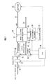
FIG. 1 is a view showing an overall configuration of a fuel cell device of the present invention; -
FIG. 2 is a flow chart indicating a start-up control and a normal electric distribution control of a fuel cell stack; and -
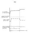
FIG. 3 is a timing chart during start-up of the fuel cell stack. - An example of an embodiment of the present invention will be explained with reference to
FIGS. 1 through 3 . With reference toFIG. 1 , a fuel cell device of the present embodiment is equipped with afuel cell stack 20, ananode inlet channel 40 which supplies hydrogen as a fuel gas to thefuel cell stack 20, acathode inlet channel 51 which supplies air as an oxidant gas to thefuel cell stack 20, a current adjustment element (a transistor, FET and the like. Corresponds to a current adjustment unit of the present invention) 30 which is connected to ananode electrode 22 and acathode electrode 23 of thefuel cell stack 20, and which adjusts current supplied from thefuel cell stack 20 to anelectric load 31, and an ECU (Electronic Control Unit, corresponds to a control unit of the present invention) 60 which carries out overall control of the fuel cell device. - The
fuel cell stack 20 is provided with an electrolyte membrane-electrode assembly (a membrane electrode assembly) which sandwiches a solidpolymer electrolyte membrane 21 with theanode electrode 22 and thecathode electrode 23, and the stack is configured by stacking the electrolyte membrane-electrode assembly and a separator not shown alternately. In this case, a gas channel is formed between the electrolyte membrane-electrode assembly and the separator. - The
anode inlet channel 40 is connected to a hydrogen tank not shown, and is provided with ashutoff valve 43, a regulator 44, and anejector 45. The supply flow rate of the hydrogen to theanode electrode 22 is adjusted by controlling the operation of theshutoff valve 43 and the regulator 44 with a control signal output from theECU 60. - Further, the outlet of the
anode electrode 22 and theejector 45 is connected with ananode outlet channel 41, so that the hydrogen ejected from theanode electrode 22 without being used is supplied again from theejector 45 to theanode electrode 22. Moreover, theanode outlet channel 41 is connected with apurge valve 46. - An anode
exhaust temperature sensor 42 which detects the temperature of a gas emitted to the anode outlet channel 41 (anode exhaust gas) is provided to theanode outlet channel 41 at the vicinity of connection with theanode electrode 22. The temperature of the anode exhaust gas is approximately equal to the temperature of thefuel cell stack 20, and the two temperatures bear a proportional relationship. Therefore, the ECU 60 may recognize the temperature of thefuel cell stack 20 from the temperature detection signal of the anodeexhaust temperature sensor 42. - The configuration of the
ECU 60 recognizing the temperature of thefuel cell stack 20 from the detected temperature of the anodeexhaust temperature sensor 42 corresponds to a stack temperature recognition unit of the present invention. Further, the stack temperature recognition unit may be configured to provide a temperature sensor inside thefuel cell stack 20 and to directly detect the temperature of thefuel cell stack 20. Moreover, the stack temperature recognition unit may be configured to estimate the temperature of a specific group of cells from the power generation status of a plurality of the cells constituting thefuel cell stack 20, and to recognize the temperature of thefuel cell stack 20 from the estimated temperature. - An
air pump 50 is connected to thecathode inlet channel 51. And the flow rate of the air supplied from thecathode inlet channel 51 to thecathode electrode 23 is adjusted by controlling the number of revolutions of theair pump 50 by a control signal output from theECU 60. - The ECU 60 is an electronic unit configured from a CPU (Central Processing Unit), a memory and the like, and the
ECU 60 functions as a control unit of the present invention by making the CPU execute a control program of the fuel cell device. The ECU 60 executes a start-up control to be explained later at a start-up (beginning of power generation operation) of thefuel cell stack 20, and after completing the start-up control, transits to a normal electric distribution control of controlling the supply flow rate of hydrogen to theanode electrode 22 and the supply flow rate of air to thecathode electrode 23 so that a target current set in accordance with a required current from theelectric load 31 is supplied from thefuel cell stack 20 to theelectric load 31. - Next, the process of the start-up control and the normal electric distribution control of the
fuel cell stack 20 by theECU 60 will be explained with reference to the flow chart shown inFIG. 2 . - When a start-up operation of the fuel cell stack 20 (in the case where the fuel cell device is mounted on a fuel cell vehicle, the operation of a starting switch by a driver, and the like) is carried out, the
ECU 60 opens theshutoff valve 43 inSTEP 1 and at the same time adjusts the supply pressure of hydrogen with the regulator 44, and starts start-up purge of supplying hydrogen to theanode electrode 22. - In subsequent STEP 2, the ECU 60 determines whether or not the start-up purge is completed, that is, whether or not the interior of the
anode electrode 22 is filled with hydrogen. The completion of the start-up purge is determined by the lapsed time from the beginning of supply of hydrogen, the change of the cell voltage of thefuel cell stack 20 or the like. Then, the process proceeds to STEP 3 when the start-up purge is completed, and proceeds to STEP 4 after timing the lapsed time after completion of the start-up purge. On the other hand, the process does not proceed to STEP 3 when the start-up purge is not completed, and branches to STEP 4. - In STEP 4, the ECU 60 recognizes the temperature of the
fuel cell stack 20 on the basis of the temperature detection signal of the anodeexhaust temperature sensor 42. In subsequent STEP 5, the ECU 60 determines whether or not the temperature of thefuel cell stack 20 is higher than freezing point. The process proceeds to STEP 6 in the case where the temperature of thefuel cell stack 20 is higher than freezing point, and branches toSTEP 20 in the case where the temperature of thefuel cell stack 20 is below freezing point. - In
STEP 20, the ECU 60 executes a low temperature start-up process, and proceeds to STEP 9. The low temperature start-up process is a process of activating thefuel cell stack 20 while giving priority to power generation stability. Further, in STEP 6, theECU 60 determines whether or not the lapsed time from the completion of the start-up purge is equal to or more than a predetermined time (which is set assuming the time necessary from the completion of the start-up purge to the time the interior of theanode outlet channel 41 is filled with hydrogen). - Thereafter, after the lapsed time from the completion of the start-up purge becomes equal to or more than the predetermined time, there is no fear of the occurrence of the deterioration of the
electrolyte membrane 21 which is caused by an oxidation-reduction reaction carried out by the presence of the layer of hydrogen and layer of air inside theanode electrode 22. Therefore, in this case, the process branches toSTEP 30, and theECU 60 executes the normal electric distribution control of determining the supply flow rate of hydrogen and oxygen, by a power generation command which is set according to the current command value. - On the other hand, in STEP 6, when the lapsed time from the completion of the start-up purge did not reach the predetermined time, the process proceeds to STEP 7. Thereafter, the ECU 60 determines whether or not an electric distribution preparation to the
electric load 31 is completed (whether or not theelectric load 31 is capable of receiving electricity). - If the electric distribution preparation is not completed in STEP 7, the process branches to STEP 40, and the
ECU 60 sets the current command value with respect to thecurrent adjustment element 30 to zero (stop current supply), and sets the supply flow rate of air to thecathode electrode 23 to a predetermined air flow rate (constant flow rate). - Further, when the electric distribution preparation is completed in STEP 7, the process proceeds to STEP 8, and the
ECU 60 sets the current command value with respect to thecurrent adjustment element 30 to a predetermined current value, and sets the supply flow rate of air to thecathode electrode 23 to a predetermined air flow rate (constant flow rate). - The predetermined current value is set to a current value which is larger than the current value during idling of the
fuel cell stack 20, that is, the current value supplied from thefuel cell stack 20 to theelectric load 31 when thefuel cell stack 20 is in an idling state (a minimum current value necessary for power generation operation of thefuel cell stack 20, for example, a current value necessary for operating electrical accessories used for power generation operation of the fuel cell stack 20). - By supplying current larger than that during idling from the
fuel cell stack 20 to theelectric load 31, during execution of the start-up purge and during the completion of the start-up purge to the lapse of the predetermined time, it becomes possible to suppress the deterioration of theelectrolyte membrane 21, which occurs from thecathode electrode 23 exhibiting high potential. - Next,
FIG. 3 is a timing chart which represents the transition of the cell voltage of thefuel cell stack 20, the supply current from thefuel cell stack 20 to theelectric load 31, and the supply flow rate of air to thecathode electrode 23, during execution of the start-up control, with the axis of abscissas representing time (t). InFIG. 3 , t0 is a point in time when the start-up command is made, t1 is a point in time when the electric distribution preparation is completed and the current supply from thefuel cell stack 20 to theelectric load 31 is started, and t2 is a point in time when the interior of theanode electrode 22 and theanode outlet channel 41 is filled with hydrogen, and the control transited from the start-up control to the normal electric distribution control. - From
FIG. 3 , it becomes apparent that the rise of the cell voltage of thefuel cell stack 20 is suppressed and the deterioration of theelectrolyte membrane 21 is suppressed, by the current supply from thefuel cell stack 20 to theelectric load 31 in the time period of t1 to t2. Further, by making the supply flow rate of air to thecathode electrode 23 constant, the current supplied from thefuel cell stack 20 to theelectric load 31 is constant at equal to or lower than a stability OK current threshold value. - In the present embodiment, the control is transited from the start-up control to the normal electric distribution control when the predetermined time lapsed from the completion of the start-up purge in STEPS 3 through 6 in
FIG. 2 . However, it may be set so that the control transits from the start-up control to the normal electric distribution control at the time of completion of the start-up purge. - Further, the supply flow rate of air to the cathode electrode is made constant during execution of the start-up control, however, the effect of the present invention may be obtained even in the case where the supply flow rate is changed.
- Further, in the present embodiment, it is determined whether or not the temperature Tfc of the
fuel cell stack 20 is higher than freezing point in STEP 5, and the process of supplying current larger than that during idling from thefuel cell stack 20 to theelectric load 31 is carried out in STEP 8 only when the temperature Tfc of thefuel cell stack 20 is higher than freezing point. However, the effect of the present invention may be obtained even in the case where the process of STEP 8 is carried out without carrying out the determination. - A fuel cell device is equipped with an
ECU 60 which executes a start-up control of afuel cell stack 20, and executes a normal electric distribution control, after completion of the start-up control, for controlling a supply flow rate of a fuel gas to an anode electrode and a supply flow rate of an oxidant gas to a cathode electrode, so that a predetermined target current is supplied from thefuel cell stack 20 to anelectric load 31. TheECU 60 makes acurrent adjustment element 30 to be in a state where a current larger than a minimum current necessary for thefuel cell stack 20 in the normal electric distribution control is supplied from thefuel cell stack 20 to theelectric load 31, in the start-up control, during the period from starting of the supply of hydrogen to theanode electrode 22 until a gas channel of theanode electrode 22 is filled with hydrogen.
Claims (4)
- A fuel cell device, comprising:a fuel cell stack configured from a plurality of membrane electrode assemblies, each of which is formed by arranging an anode electrode and a cathode electrode having a gas channel with an electrolyte membrane sandwiched in-between;a fuel gas adjustment unit which adjusts a supply flow rate of a fuel gas to the anode electrode;an oxidant gas adjustment unit which adjusts a supply flow rate of an oxidant gas to the cathode electrode;a current adjustment unit which adjusts a supply current from the fuel cell stack to an electric load connected to the fuel cell stack; anda control unit which carries out a start-up control of the fuel cell stack, and which executes a normal electric distribution control, after completion of the start-up control, for controlling the supply flow rate of the fuel gas to the anode electrode and the supply flow rate of the oxidant gas to the cathode electrode, so that a predetermined target current is supplied from the fuel cell stack to the electric load;wherein, in the start-up control, the control unit makes the current adjustment unit supply to be in a state where a current larger than a minimum current, which is the current necessary for power generation operation by the fuel cell stack in the normal electric distribution control, is supplied from the fuel cell stack to the electric load, during the period from the start of supply of the fuel gas to the anode electrode until a gas channel of the anode electrode is filled with the fuel gas.
- The fuel cell device according to Claim 1,
wherein, in the start-up control, the control unit terminates the process of making the current adjustment unit to be in a state where a current larger than the minimum current is supplied from the fuel cell stack to the electric load, and transits to the normal electric distribution control, when a wait time, which is determined assuming the time from the point in time the gas channel of the anode electrode is filled with the fuel gas to the point in time an anode outlet channel connecting the outlet and the inlet of the gas channel of the anode electrode is filled with the fuel gas, lapses. - The fuel cell device according to Claim 1,
further comprising a stack temperature recognition unit which recognizes the temperature of the fuel cell stack,
wherein, in the start-up control, the control unit makes the current adjustment unit to be in a state where a current larger than the minimum current necessary for the power generation operation of the fuel cell stack in the normal electric distribution control is supplied from the fuel cell stack to the electric load, only when the temperature of the fuel cell stack is higher than the freezing point. - The fuel cell device according to any one of Claims 1 to 3,
wherein the control unit maintains the flow rate of the oxidant gas supplied to the cathode electrode to a constant flow rate, during execution of the start-up control.
Applications Claiming Priority (2)
| Application Number | Priority Date | Filing Date | Title |
|---|---|---|---|
| JP2010005931 | 2010-01-14 | ||
| JP2010276306A JP5469047B2 (en) | 2010-01-14 | 2010-12-10 | Fuel cell device |
Publications (2)
| Publication Number | Publication Date |
|---|---|
| EP2357700A1 true EP2357700A1 (en) | 2011-08-17 |
| EP2357700B1 EP2357700B1 (en) | 2013-04-24 |
Family
ID=43821809
Family Applications (1)
| Application Number | Title | Priority Date | Filing Date |
|---|---|---|---|
| EP11150971.7A Not-in-force EP2357700B1 (en) | 2010-01-14 | 2011-01-14 | Fuel cell device |
Country Status (3)
| Country | Link |
|---|---|
| US (1) | US9166239B2 (en) |
| EP (1) | EP2357700B1 (en) |
| JP (1) | JP5469047B2 (en) |
Families Citing this family (4)
| Publication number | Priority date | Publication date | Assignee | Title |
|---|---|---|---|---|
| JP5438745B2 (en) * | 2011-11-28 | 2014-03-12 | 本田技研工業株式会社 | Fluid supply system |
| CN111969229B (en) * | 2019-01-07 | 2021-08-31 | 中氢新能技术有限公司 | Control system for exhaust valve angle of methanol fuel cell |
| AT522847B1 (en) * | 2019-06-13 | 2022-01-15 | Avl List Gmbh | Fuel cell system and method for setting an operating mode of a fuel cell system |
| JP7152373B2 (en) * | 2019-09-20 | 2022-10-12 | 本田技研工業株式会社 | Low temperature startup method for fuel cell system and fuel cell system |
Citations (6)
| Publication number | Priority date | Publication date | Assignee | Title |
|---|---|---|---|---|
| EP1513209A2 (en) * | 2003-09-08 | 2005-03-09 | HONDA MOTOR CO., Ltd. | Method and system for starting up fuel cell stack at subzero temperatures, and method of designing fuel cell stack |
| JP2006100093A (en) * | 2004-09-29 | 2006-04-13 | Honda Motor Co Ltd | Starting the fuel cell |
| WO2006117969A1 (en) * | 2005-04-26 | 2006-11-09 | Nissan Motor Co., Ltd. | Fuel cell system |
| JP2009064681A (en) | 2007-09-06 | 2009-03-26 | Nissan Motor Co Ltd | Fuel cell starting method, fuel cell starting device and vehicle equipped with the starting device |
| US20090104489A1 (en) * | 2007-10-17 | 2009-04-23 | Samsung Sdi Co., Ltd. | Air breathing type polymer electrolyte membrane fuel cell and operating method thereof |
| US20090176135A1 (en) * | 2006-04-07 | 2009-07-09 | Kazuo Saito | Operating Fuel Cell During Down Time on Cryogenic Hydrogen Boil-Off |
Family Cites Families (12)
| Publication number | Priority date | Publication date | Assignee | Title |
|---|---|---|---|---|
| JPH044761A (en) | 1990-04-19 | 1992-01-09 | Fuji Electric Co Ltd | Fuel-cell generator |
| JP3111787B2 (en) | 1994-01-20 | 2000-11-27 | 富士電機株式会社 | Fuel cell power generator and start-up method thereof |
| US5798186A (en) | 1996-06-07 | 1998-08-25 | Ballard Power Systems Inc. | Method and apparatus for commencing operation of a fuel cell electric power generation system below the freezing temperature of water |
| DE10297626B4 (en) | 2002-01-04 | 2013-04-18 | Utc Fuel Cells, Llc | A method of starting up a fuel cell system having an anode exhaust gas recycle loop |
| JP3916150B2 (en) * | 2002-11-28 | 2007-05-16 | 本田技研工業株式会社 | Fuel cell system |
| US7282286B2 (en) * | 2002-11-28 | 2007-10-16 | Honda Motor Co., Ltd. | Start-up method for fuel cell |
| JP4959106B2 (en) * | 2002-11-29 | 2012-06-20 | 本田技研工業株式会社 | Starting method of fuel cell system |
| JP4309323B2 (en) * | 2004-09-29 | 2009-08-05 | 本田技研工業株式会社 | Starting the fuel cell |
| JP5034160B2 (en) * | 2004-11-26 | 2012-09-26 | 日産自動車株式会社 | Fuel cell system |
| JP2007027078A (en) * | 2005-06-13 | 2007-02-01 | Nissan Motor Co Ltd | Fuel cell system |
| CA2597119C (en) | 2005-06-13 | 2013-04-02 | Nissan Motor Co., Ltd. | Fuel cell start-up control system |
| JP2009259481A (en) * | 2008-04-14 | 2009-11-05 | Toyota Motor Corp | Fuel cell system and operation method of fuel cell |
-
2010
- 2010-12-10 JP JP2010276306A patent/JP5469047B2/en not_active Expired - Fee Related
-
2011
- 2011-01-13 US US13/006,150 patent/US9166239B2/en not_active Expired - Fee Related
- 2011-01-14 EP EP11150971.7A patent/EP2357700B1/en not_active Not-in-force
Patent Citations (6)
| Publication number | Priority date | Publication date | Assignee | Title |
|---|---|---|---|---|
| EP1513209A2 (en) * | 2003-09-08 | 2005-03-09 | HONDA MOTOR CO., Ltd. | Method and system for starting up fuel cell stack at subzero temperatures, and method of designing fuel cell stack |
| JP2006100093A (en) * | 2004-09-29 | 2006-04-13 | Honda Motor Co Ltd | Starting the fuel cell |
| WO2006117969A1 (en) * | 2005-04-26 | 2006-11-09 | Nissan Motor Co., Ltd. | Fuel cell system |
| US20090176135A1 (en) * | 2006-04-07 | 2009-07-09 | Kazuo Saito | Operating Fuel Cell During Down Time on Cryogenic Hydrogen Boil-Off |
| JP2009064681A (en) | 2007-09-06 | 2009-03-26 | Nissan Motor Co Ltd | Fuel cell starting method, fuel cell starting device and vehicle equipped with the starting device |
| US20090104489A1 (en) * | 2007-10-17 | 2009-04-23 | Samsung Sdi Co., Ltd. | Air breathing type polymer electrolyte membrane fuel cell and operating method thereof |
Also Published As
| Publication number | Publication date |
|---|---|
| JP5469047B2 (en) | 2014-04-09 |
| US9166239B2 (en) | 2015-10-20 |
| US20110171548A1 (en) | 2011-07-14 |
| EP2357700B1 (en) | 2013-04-24 |
| JP2011165655A (en) | 2011-08-25 |
Similar Documents
| Publication | Publication Date | Title |
|---|---|---|
| US8435686B2 (en) | Fuel cell system | |
| US8263278B2 (en) | Fuel cell system and its operation method | |
| CN102800884B (en) | Fuel cell system and control method thereof | |
| JP5391226B2 (en) | Fuel cell system and control method thereof | |
| JP5215583B2 (en) | Fuel cell system | |
| EP3392948B1 (en) | Fuel cell system and control method for fuel cell system | |
| CN105609831B (en) | The method for controlling of operation of fuel cell system and fuel cell system | |
| CN102918694A (en) | Fuel cell system and control method therefor | |
| CN101322272A (en) | fuel cell system | |
| US9166239B2 (en) | Fuel cell device | |
| JP2013206625A (en) | Fuel cell system | |
| EP3483969B1 (en) | Fuel cell system and method of controlling the same | |
| CN101467295B (en) | Fuel cell system | |
| CN105609830B (en) | Fuel cell system and its control method | |
| EP3121890B1 (en) | Fuel cell system | |
| JP3698101B2 (en) | Control device for fuel reforming fuel cell system | |
| JP6322925B2 (en) | Fuel cell system | |
| JP5144152B2 (en) | Discharge system | |
| JP4739938B2 (en) | Fuel cell system | |
| JP4904719B2 (en) | Fuel cell system, control method thereof, and vehicle equipped with the same | |
| JP5172488B2 (en) | Fuel cell system | |
| JP2016122548A (en) | Fuel cell system | |
| JP2008140642A (en) | Fuel cell system | |
| JP2009048974A (en) | Fuel cell system | |
| JP2009238640A (en) | Fuel cell system |
Legal Events
| Date | Code | Title | Description |
|---|---|---|---|
| PUAI | Public reference made under article 153(3) epc to a published international application that has entered the european phase |
Free format text: ORIGINAL CODE: 0009012 |
|
| 17P | Request for examination filed |
Effective date: 20110114 |
|
| AK | Designated contracting states |
Kind code of ref document: A1 Designated state(s): AL AT BE BG CH CY CZ DE DK EE ES FI FR GB GR HR HU IE IS IT LI LT LU LV MC MK MT NL NO PL PT RO RS SE SI SK SM TR |
|
| AX | Request for extension of the european patent |
Extension state: BA ME |
|
| GRAP | Despatch of communication of intention to grant a patent |
Free format text: ORIGINAL CODE: EPIDOSNIGR1 |
|
| GRAS | Grant fee paid |
Free format text: ORIGINAL CODE: EPIDOSNIGR3 |
|
| GRAA | (expected) grant |
Free format text: ORIGINAL CODE: 0009210 |
|
| RIN1 | Information on inventor provided before grant (corrected) |
Inventor name: MATSUMOTO, YUJI Inventor name: MIYATA, KOICHIRO Inventor name: SHIRASAKA, TAKUYA |
|
| AK | Designated contracting states |
Kind code of ref document: B1 Designated state(s): AL AT BE BG CH CY CZ DE DK EE ES FI FR GB GR HR HU IE IS IT LI LT LU LV MC MK MT NL NO PL PT RO RS SE SI SK SM TR |
|
| REG | Reference to a national code |
Ref country code: GB Ref legal event code: FG4D |
|
| REG | Reference to a national code |
Ref country code: CH Ref legal event code: EP |
|
| REG | Reference to a national code |
Ref country code: AT Ref legal event code: REF Ref document number: 609097 Country of ref document: AT Kind code of ref document: T Effective date: 20130515 |
|
| REG | Reference to a national code |
Ref country code: IE Ref legal event code: FG4D |
|
| REG | Reference to a national code |
Ref country code: DE Ref legal event code: R096 Ref document number: 602011001411 Country of ref document: DE Effective date: 20130620 |
|
| REG | Reference to a national code |
Ref country code: AT Ref legal event code: MK05 Ref document number: 609097 Country of ref document: AT Kind code of ref document: T Effective date: 20130424 |
|
| REG | Reference to a national code |
Ref country code: LT Ref legal event code: MG4D |
|
| REG | Reference to a national code |
Ref country code: NL Ref legal event code: VDEP Effective date: 20130424 |
|
| PG25 | Lapsed in a contracting state [announced via postgrant information from national office to epo] |
Ref country code: SI Free format text: LAPSE BECAUSE OF FAILURE TO SUBMIT A TRANSLATION OF THE DESCRIPTION OR TO PAY THE FEE WITHIN THE PRESCRIBED TIME-LIMIT Effective date: 20130424 Ref country code: BE Free format text: LAPSE BECAUSE OF FAILURE TO SUBMIT A TRANSLATION OF THE DESCRIPTION OR TO PAY THE FEE WITHIN THE PRESCRIBED TIME-LIMIT Effective date: 20130424 Ref country code: ES Free format text: LAPSE BECAUSE OF FAILURE TO SUBMIT A TRANSLATION OF THE DESCRIPTION OR TO PAY THE FEE WITHIN THE PRESCRIBED TIME-LIMIT Effective date: 20130804 Ref country code: FI Free format text: LAPSE BECAUSE OF FAILURE TO SUBMIT A TRANSLATION OF THE DESCRIPTION OR TO PAY THE FEE WITHIN THE PRESCRIBED TIME-LIMIT Effective date: 20130424 Ref country code: AT Free format text: LAPSE BECAUSE OF FAILURE TO SUBMIT A TRANSLATION OF THE DESCRIPTION OR TO PAY THE FEE WITHIN THE PRESCRIBED TIME-LIMIT Effective date: 20130424 Ref country code: LT Free format text: LAPSE BECAUSE OF FAILURE TO SUBMIT A TRANSLATION OF THE DESCRIPTION OR TO PAY THE FEE WITHIN THE PRESCRIBED TIME-LIMIT Effective date: 20130424 Ref country code: GR Free format text: LAPSE BECAUSE OF FAILURE TO SUBMIT A TRANSLATION OF THE DESCRIPTION OR TO PAY THE FEE WITHIN THE PRESCRIBED TIME-LIMIT Effective date: 20130725 Ref country code: PT Free format text: LAPSE BECAUSE OF FAILURE TO SUBMIT A TRANSLATION OF THE DESCRIPTION OR TO PAY THE FEE WITHIN THE PRESCRIBED TIME-LIMIT Effective date: 20130826 Ref country code: SE Free format text: LAPSE BECAUSE OF FAILURE TO SUBMIT A TRANSLATION OF THE DESCRIPTION OR TO PAY THE FEE WITHIN THE PRESCRIBED TIME-LIMIT Effective date: 20130424 Ref country code: IS Free format text: LAPSE BECAUSE OF FAILURE TO SUBMIT A TRANSLATION OF THE DESCRIPTION OR TO PAY THE FEE WITHIN THE PRESCRIBED TIME-LIMIT Effective date: 20130824 Ref country code: NO Free format text: LAPSE BECAUSE OF FAILURE TO SUBMIT A TRANSLATION OF THE DESCRIPTION OR TO PAY THE FEE WITHIN THE PRESCRIBED TIME-LIMIT Effective date: 20130724 |
|
| PG25 | Lapsed in a contracting state [announced via postgrant information from national office to epo] |
Ref country code: RS Free format text: LAPSE BECAUSE OF FAILURE TO SUBMIT A TRANSLATION OF THE DESCRIPTION OR TO PAY THE FEE WITHIN THE PRESCRIBED TIME-LIMIT Effective date: 20130424 Ref country code: LV Free format text: LAPSE BECAUSE OF FAILURE TO SUBMIT A TRANSLATION OF THE DESCRIPTION OR TO PAY THE FEE WITHIN THE PRESCRIBED TIME-LIMIT Effective date: 20130424 Ref country code: CY Free format text: LAPSE BECAUSE OF FAILURE TO SUBMIT A TRANSLATION OF THE DESCRIPTION OR TO PAY THE FEE WITHIN THE PRESCRIBED TIME-LIMIT Effective date: 20130424 Ref country code: HR Free format text: LAPSE BECAUSE OF FAILURE TO SUBMIT A TRANSLATION OF THE DESCRIPTION OR TO PAY THE FEE WITHIN THE PRESCRIBED TIME-LIMIT Effective date: 20130424 Ref country code: PL Free format text: LAPSE BECAUSE OF FAILURE TO SUBMIT A TRANSLATION OF THE DESCRIPTION OR TO PAY THE FEE WITHIN THE PRESCRIBED TIME-LIMIT Effective date: 20130424 Ref country code: BG Free format text: LAPSE BECAUSE OF FAILURE TO SUBMIT A TRANSLATION OF THE DESCRIPTION OR TO PAY THE FEE WITHIN THE PRESCRIBED TIME-LIMIT Effective date: 20130724 |
|
| PG25 | Lapsed in a contracting state [announced via postgrant information from national office to epo] |
Ref country code: SK Free format text: LAPSE BECAUSE OF FAILURE TO SUBMIT A TRANSLATION OF THE DESCRIPTION OR TO PAY THE FEE WITHIN THE PRESCRIBED TIME-LIMIT Effective date: 20130424 Ref country code: CZ Free format text: LAPSE BECAUSE OF FAILURE TO SUBMIT A TRANSLATION OF THE DESCRIPTION OR TO PAY THE FEE WITHIN THE PRESCRIBED TIME-LIMIT Effective date: 20130424 Ref country code: DK Free format text: LAPSE BECAUSE OF FAILURE TO SUBMIT A TRANSLATION OF THE DESCRIPTION OR TO PAY THE FEE WITHIN THE PRESCRIBED TIME-LIMIT Effective date: 20130424 Ref country code: EE Free format text: LAPSE BECAUSE OF FAILURE TO SUBMIT A TRANSLATION OF THE DESCRIPTION OR TO PAY THE FEE WITHIN THE PRESCRIBED TIME-LIMIT Effective date: 20130424 |
|
| PG25 | Lapsed in a contracting state [announced via postgrant information from national office to epo] |
Ref country code: NL Free format text: LAPSE BECAUSE OF FAILURE TO SUBMIT A TRANSLATION OF THE DESCRIPTION OR TO PAY THE FEE WITHIN THE PRESCRIBED TIME-LIMIT Effective date: 20130424 Ref country code: IT Free format text: LAPSE BECAUSE OF FAILURE TO SUBMIT A TRANSLATION OF THE DESCRIPTION OR TO PAY THE FEE WITHIN THE PRESCRIBED TIME-LIMIT Effective date: 20130424 Ref country code: RO Free format text: LAPSE BECAUSE OF FAILURE TO SUBMIT A TRANSLATION OF THE DESCRIPTION OR TO PAY THE FEE WITHIN THE PRESCRIBED TIME-LIMIT Effective date: 20130424 |
|
| PLBE | No opposition filed within time limit |
Free format text: ORIGINAL CODE: 0009261 |
|
| STAA | Information on the status of an ep patent application or granted ep patent |
Free format text: STATUS: NO OPPOSITION FILED WITHIN TIME LIMIT |
|
| 26N | No opposition filed |
Effective date: 20140127 |
|
| REG | Reference to a national code |
Ref country code: DE Ref legal event code: R097 Ref document number: 602011001411 Country of ref document: DE Effective date: 20140127 |
|
| PG25 | Lapsed in a contracting state [announced via postgrant information from national office to epo] |
Ref country code: LU Free format text: LAPSE BECAUSE OF FAILURE TO SUBMIT A TRANSLATION OF THE DESCRIPTION OR TO PAY THE FEE WITHIN THE PRESCRIBED TIME-LIMIT Effective date: 20140114 |
|
| REG | Reference to a national code |
Ref country code: CH Ref legal event code: PL |
|
| PG25 | Lapsed in a contracting state [announced via postgrant information from national office to epo] |
Ref country code: CH Free format text: LAPSE BECAUSE OF NON-PAYMENT OF DUE FEES Effective date: 20140131 Ref country code: LI Free format text: LAPSE BECAUSE OF NON-PAYMENT OF DUE FEES Effective date: 20140131 |
|
| REG | Reference to a national code |
Ref country code: FR Ref legal event code: ST Effective date: 20140930 |
|
| REG | Reference to a national code |
Ref country code: IE Ref legal event code: MM4A |
|
| PG25 | Lapsed in a contracting state [announced via postgrant information from national office to epo] |
Ref country code: FR Free format text: LAPSE BECAUSE OF NON-PAYMENT OF DUE FEES Effective date: 20140131 |
|
| PG25 | Lapsed in a contracting state [announced via postgrant information from national office to epo] |
Ref country code: IE Free format text: LAPSE BECAUSE OF NON-PAYMENT OF DUE FEES Effective date: 20140114 |
|
| PG25 | Lapsed in a contracting state [announced via postgrant information from national office to epo] |
Ref country code: MC Free format text: LAPSE BECAUSE OF FAILURE TO SUBMIT A TRANSLATION OF THE DESCRIPTION OR TO PAY THE FEE WITHIN THE PRESCRIBED TIME-LIMIT Effective date: 20130424 |
|
| PGFP | Annual fee paid to national office [announced via postgrant information from national office to epo] |
Ref country code: DE Payment date: 20150106 Year of fee payment: 5 |
|
| PGFP | Annual fee paid to national office [announced via postgrant information from national office to epo] |
Ref country code: GB Payment date: 20150114 Year of fee payment: 5 |
|
| PG25 | Lapsed in a contracting state [announced via postgrant information from national office to epo] |
Ref country code: MT Free format text: LAPSE BECAUSE OF FAILURE TO SUBMIT A TRANSLATION OF THE DESCRIPTION OR TO PAY THE FEE WITHIN THE PRESCRIBED TIME-LIMIT Effective date: 20130424 |
|
| PG25 | Lapsed in a contracting state [announced via postgrant information from national office to epo] |
Ref country code: SM Free format text: LAPSE BECAUSE OF FAILURE TO SUBMIT A TRANSLATION OF THE DESCRIPTION OR TO PAY THE FEE WITHIN THE PRESCRIBED TIME-LIMIT Effective date: 20130424 |
|
| PG25 | Lapsed in a contracting state [announced via postgrant information from national office to epo] |
Ref country code: TR Free format text: LAPSE BECAUSE OF FAILURE TO SUBMIT A TRANSLATION OF THE DESCRIPTION OR TO PAY THE FEE WITHIN THE PRESCRIBED TIME-LIMIT Effective date: 20130424 Ref country code: HU Free format text: LAPSE BECAUSE OF FAILURE TO SUBMIT A TRANSLATION OF THE DESCRIPTION OR TO PAY THE FEE WITHIN THE PRESCRIBED TIME-LIMIT; INVALID AB INITIO Effective date: 20110114 |
|
| REG | Reference to a national code |
Ref country code: DE Ref legal event code: R119 Ref document number: 602011001411 Country of ref document: DE |
|
| GBPC | Gb: european patent ceased through non-payment of renewal fee |
Effective date: 20160114 |
|
| PG25 | Lapsed in a contracting state [announced via postgrant information from national office to epo] |
Ref country code: DE Free format text: LAPSE BECAUSE OF NON-PAYMENT OF DUE FEES Effective date: 20160802 Ref country code: GB Free format text: LAPSE BECAUSE OF NON-PAYMENT OF DUE FEES Effective date: 20160114 |
|
| PG25 | Lapsed in a contracting state [announced via postgrant information from national office to epo] |
Ref country code: MK Free format text: LAPSE BECAUSE OF FAILURE TO SUBMIT A TRANSLATION OF THE DESCRIPTION OR TO PAY THE FEE WITHIN THE PRESCRIBED TIME-LIMIT Effective date: 20130424 |
|
| PG25 | Lapsed in a contracting state [announced via postgrant information from national office to epo] |
Ref country code: AL Free format text: LAPSE BECAUSE OF FAILURE TO SUBMIT A TRANSLATION OF THE DESCRIPTION OR TO PAY THE FEE WITHIN THE PRESCRIBED TIME-LIMIT Effective date: 20130424 |