EP2357511A1 - Bezel attachment structure and liquid crystal module - Google Patents
Bezel attachment structure and liquid crystal module Download PDFInfo
- Publication number
- EP2357511A1 EP2357511A1 EP10196251A EP10196251A EP2357511A1 EP 2357511 A1 EP2357511 A1 EP 2357511A1 EP 10196251 A EP10196251 A EP 10196251A EP 10196251 A EP10196251 A EP 10196251A EP 2357511 A1 EP2357511 A1 EP 2357511A1
- Authority
- EP
- European Patent Office
- Prior art keywords
- frame
- bezel
- component
- components
- engaging
- Prior art date
- Legal status (The legal status is an assumption and is not a legal conclusion. Google has not performed a legal analysis and makes no representation as to the accuracy of the status listed.)
- Granted
Links
Images


Classifications
-
- G—PHYSICS
- G02—OPTICS
- G02F—OPTICAL DEVICES OR ARRANGEMENTS FOR THE CONTROL OF LIGHT BY MODIFICATION OF THE OPTICAL PROPERTIES OF THE MEDIA OF THE ELEMENTS INVOLVED THEREIN; NON-LINEAR OPTICS; FREQUENCY-CHANGING OF LIGHT; OPTICAL LOGIC ELEMENTS; OPTICAL ANALOGUE/DIGITAL CONVERTERS
- G02F1/00—Devices or arrangements for the control of the intensity, colour, phase, polarisation or direction of light arriving from an independent light source, e.g. switching, gating or modulating; Non-linear optics
- G02F1/01—Devices or arrangements for the control of the intensity, colour, phase, polarisation or direction of light arriving from an independent light source, e.g. switching, gating or modulating; Non-linear optics for the control of the intensity, phase, polarisation or colour
- G02F1/13—Devices or arrangements for the control of the intensity, colour, phase, polarisation or direction of light arriving from an independent light source, e.g. switching, gating or modulating; Non-linear optics for the control of the intensity, phase, polarisation or colour based on liquid crystals, e.g. single liquid crystal display cells
- G02F1/133—Constructional arrangements; Operation of liquid crystal cells; Circuit arrangements
- G02F1/1333—Constructional arrangements; Manufacturing methods
- G02F1/133308—Support structures for LCD panels, e.g. frames or bezels
-
- G—PHYSICS
- G02—OPTICS
- G02F—OPTICAL DEVICES OR ARRANGEMENTS FOR THE CONTROL OF LIGHT BY MODIFICATION OF THE OPTICAL PROPERTIES OF THE MEDIA OF THE ELEMENTS INVOLVED THEREIN; NON-LINEAR OPTICS; FREQUENCY-CHANGING OF LIGHT; OPTICAL LOGIC ELEMENTS; OPTICAL ANALOGUE/DIGITAL CONVERTERS
- G02F1/00—Devices or arrangements for the control of the intensity, colour, phase, polarisation or direction of light arriving from an independent light source, e.g. switching, gating or modulating; Non-linear optics
- G02F1/01—Devices or arrangements for the control of the intensity, colour, phase, polarisation or direction of light arriving from an independent light source, e.g. switching, gating or modulating; Non-linear optics for the control of the intensity, phase, polarisation or colour
- G02F1/13—Devices or arrangements for the control of the intensity, colour, phase, polarisation or direction of light arriving from an independent light source, e.g. switching, gating or modulating; Non-linear optics for the control of the intensity, phase, polarisation or colour based on liquid crystals, e.g. single liquid crystal display cells
- G02F1/133—Constructional arrangements; Operation of liquid crystal cells; Circuit arrangements
- G02F1/1333—Constructional arrangements; Manufacturing methods
- G02F1/133308—Support structures for LCD panels, e.g. frames or bezels
- G02F1/133317—Intermediate frames, e.g. between backlight housing and front frame
-
- G—PHYSICS
- G02—OPTICS
- G02F—OPTICAL DEVICES OR ARRANGEMENTS FOR THE CONTROL OF LIGHT BY MODIFICATION OF THE OPTICAL PROPERTIES OF THE MEDIA OF THE ELEMENTS INVOLVED THEREIN; NON-LINEAR OPTICS; FREQUENCY-CHANGING OF LIGHT; OPTICAL LOGIC ELEMENTS; OPTICAL ANALOGUE/DIGITAL CONVERTERS
- G02F1/00—Devices or arrangements for the control of the intensity, colour, phase, polarisation or direction of light arriving from an independent light source, e.g. switching, gating or modulating; Non-linear optics
- G02F1/01—Devices or arrangements for the control of the intensity, colour, phase, polarisation or direction of light arriving from an independent light source, e.g. switching, gating or modulating; Non-linear optics for the control of the intensity, phase, polarisation or colour
- G02F1/13—Devices or arrangements for the control of the intensity, colour, phase, polarisation or direction of light arriving from an independent light source, e.g. switching, gating or modulating; Non-linear optics for the control of the intensity, phase, polarisation or colour based on liquid crystals, e.g. single liquid crystal display cells
- G02F1/133—Constructional arrangements; Operation of liquid crystal cells; Circuit arrangements
- G02F1/1333—Constructional arrangements; Manufacturing methods
- G02F1/133308—Support structures for LCD panels, e.g. frames or bezels
- G02F1/13332—Front frames
-
- G—PHYSICS
- G02—OPTICS
- G02F—OPTICAL DEVICES OR ARRANGEMENTS FOR THE CONTROL OF LIGHT BY MODIFICATION OF THE OPTICAL PROPERTIES OF THE MEDIA OF THE ELEMENTS INVOLVED THEREIN; NON-LINEAR OPTICS; FREQUENCY-CHANGING OF LIGHT; OPTICAL LOGIC ELEMENTS; OPTICAL ANALOGUE/DIGITAL CONVERTERS
- G02F1/00—Devices or arrangements for the control of the intensity, colour, phase, polarisation or direction of light arriving from an independent light source, e.g. switching, gating or modulating; Non-linear optics
- G02F1/01—Devices or arrangements for the control of the intensity, colour, phase, polarisation or direction of light arriving from an independent light source, e.g. switching, gating or modulating; Non-linear optics for the control of the intensity, phase, polarisation or colour
- G02F1/13—Devices or arrangements for the control of the intensity, colour, phase, polarisation or direction of light arriving from an independent light source, e.g. switching, gating or modulating; Non-linear optics for the control of the intensity, phase, polarisation or colour based on liquid crystals, e.g. single liquid crystal display cells
- G02F1/133—Constructional arrangements; Operation of liquid crystal cells; Circuit arrangements
- G02F1/1333—Constructional arrangements; Manufacturing methods
- G02F1/133308—Support structures for LCD panels, e.g. frames or bezels
- G02F1/133325—Assembling processes
-
- G—PHYSICS
- G02—OPTICS
- G02F—OPTICAL DEVICES OR ARRANGEMENTS FOR THE CONTROL OF LIGHT BY MODIFICATION OF THE OPTICAL PROPERTIES OF THE MEDIA OF THE ELEMENTS INVOLVED THEREIN; NON-LINEAR OPTICS; FREQUENCY-CHANGING OF LIGHT; OPTICAL LOGIC ELEMENTS; OPTICAL ANALOGUE/DIGITAL CONVERTERS
- G02F1/00—Devices or arrangements for the control of the intensity, colour, phase, polarisation or direction of light arriving from an independent light source, e.g. switching, gating or modulating; Non-linear optics
- G02F1/01—Devices or arrangements for the control of the intensity, colour, phase, polarisation or direction of light arriving from an independent light source, e.g. switching, gating or modulating; Non-linear optics for the control of the intensity, phase, polarisation or colour
- G02F1/13—Devices or arrangements for the control of the intensity, colour, phase, polarisation or direction of light arriving from an independent light source, e.g. switching, gating or modulating; Non-linear optics for the control of the intensity, phase, polarisation or colour based on liquid crystals, e.g. single liquid crystal display cells
- G02F1/133—Constructional arrangements; Operation of liquid crystal cells; Circuit arrangements
- G02F1/1333—Constructional arrangements; Manufacturing methods
- G02F1/133308—Support structures for LCD panels, e.g. frames or bezels
- G02F1/133328—Segmented frames
Definitions
- the present invention generally relates to a bezel attachment structure. More specifically, the present invention relates to a bezel attachment structure for a liquid crystal module.
- the bezel is typically fitted to a frame for a backlight, and then the bezel is fixed to the frame with screws.
- An improved bezel attachment structure was conceived in light of the above-mentioned problem.
- One object of the present disclosure is to provide a bezel attachment structure with which a bezel component is securely attached to a frame without the use of screws.
- a bezel attachment structure for a liquid crystal module includes a frame and a bezel.
- the frame includes a side face, a plurality of first engaging components, and a second engaging component.
- the first engaging components are formed on the side face.
- the second engaging component is formed at one end portion of the side face.
- the bezel component is attached to the side face of the frame.
- the bezel component includes a side plate, a plurality of first engaged components, a plurality of contact components, and a second engaged component.
- the side plate is disposed on the side face of the frame.
- the first engaged components are formed on the side plate.
- the first engaged components engage the first engaging components of the frame, respectively, such that the bezel component is prevented from moving relative to the side face of the frame both in upward and downward directions of the frame and in inward and outward directions of the frame with the inward and outward directions being perpendicular to the upward and downward directions of the frame.
- the contact components are formed on the side plate.
- the contact components engage the first engaging components of the frame, respectively, such that the bezel component is prevented from moving relative to the side face of the frame in a first lengthwise direction of the frame with the first lengthwise direction being perpendicular to both the upward and down directions and the inward and outward directions.
- the second engaged component is formed at one end portion of the side plate.
- the second engaged component engages the second engaging component such that the bezel component is prevented from moving relative to the side face of the frame in a second lengthwise direction of the frame.
- the second lengthwise direction is opposite to the first lengthwise direction of the frame.
- the second lengthwise direction directs from the one end portion of the side face of the frame toward the other end portion of the side face of the frame.
- FIG. 1 is a front elevational view of a liquid crystal module in accordance with one embodiment
- FIG. 2 is a bottom plan view of the liquid crystal module illustrated in FIG. 1 with an enlarged, partial bottom view of an attachment structure of the liquid crystal module in a circle C in FIG. 1 ;
- FIG. 3 is a partial cross sectional view of the liquid crystal module taken along III-III line in FIG. 2 ;
- FIG. 4 is an enlarged, partial exploded perspective view of the liquid crystal module illustrated in FIG. 1 ;
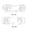
- FIG. 5A is a partial plan view of the liquid crystal module illustrating an initial state of an attachment of a bezel component of the liquid crystal module relative to a frame of the liquid crystal module;
- FIG. 5B is a partial plan view of the liquid crystal module illustrating a final state of the attachment of the bezel component relative to the frame.
- a liquid crystal module has a plurality of bezel components (e.g., two long bezel components and two short bezel components) 1, a liquid crystal panel 2, a backlight device (e.g., backlight unit) 3 and a synthetic resin frame 4.
- the backlight device 3 has a rear frame 3a, a light reflecting sheet 3b, a plurality of U-shaped cold cathode tubes 3c, and a plurality of light diffusing sheets 3d.
- the bezel components 1 form a rectangular four-piece divisible bezel that holds down an edge portion of the liquid crystal panel 2 when the bezel components 1 are coupled to the frame 4.
- Each of the bezel components 1 includes a front plate with an inner end edge portion 1a and a side plate 1b.
- the bezel components 1 are attached to four side faces 4c of the frame 4 that surrounds the backlight device 3 without the use of screws.
- Four edge portions around the liquid crystal panel 2 are surrounded by the bezel components 1.
- the liquid crystal module includes a bezel attachment structure for attaching the bezel components 1 to the frame 4.
- the rear frame 3a is made of sheet metal, and formed in a shallow box shape.
- the light reflecting sheet 3b is provided inside the rear frame 3a.
- the U-shaped cold cathode tubes 3c are installed above the light reflecting sheet 3b as a light source.
- Four edge portions around the light diffusing sheets 3d are superposed as optical sheets.
- the frame 4 is attached to four side faces of the rear frame 3a.
- the frame 4 includes panel supports 4a, a plurality of positioning ribs 4b, the side faces 4c, and a plurality of support ribs 4d. The edge portions of the light diffusing sheets 3d are held down by inner end edge portions of the frame 4.
- the four edge portions around the liquid crystal panel 2 are disposed on the panel supports 4a formed on the inner end edge portions of the frame 4.
- the edge portions of the liquid crystal panel 2 are held down by the inner end edge portions 1a of the front plate of the bezel components 1 attached to the four side faces 4c of the frame 4.
- the liquid crystal panel 2 is positioned by the positioning ribs 4b formed on an upper face of the frame 4.
- the support ribs 4d support the side plates 1b of the bezel components 1 from inside of the liquid crystal module (i.e., rear side of the side plates 1b).
- the support ribs 4d are formed spaced apart locations on the side faces 4c of the frame 4.
- a flexible wiring board 5 is connected to the liquid crystal panel 2, and is taken out through the spaces between the support ribs 4d to a lower side of the rear frame 3a.
- the flexible wiring board 5 is connected to a substrate 6 attached to a lower face (i.e., rear face) of the rear frame 3a.
- the side faces 4c of the frame 4 and the side plates 1b of the bezel components 1 include a plurality of sets of a first engaging component 7 and a first engaged component 8.
- the first engaging component 7 and the first engaged component 8 engage with each other in up and down directions (e.g., upward and downward directions of the frame 4) and forward and backward directions (e.g., inward and outward directions of the frame 4) as seen in FIG. 5B .
- the up and down directions are perpendicular to the forward and backward directions.
- the bezel components 1 are prevented from moving in the up and down directions and the forward and backward directions relative to the frame 4 when the bezel components 1 are superposed over the frame 4 as seen in FIG. 5A and slid to the left (a direction indicated by an arrow A in FIG. 5A , e.g., first lengthwise direction of the side faces 4 of the frame 4) along a lengthwise direction of the bezel components 1.
- the lengthwise direction is perpendicular to both the up and down directions and the forward and backward directions.
- the sets of the first engaging component 7 and the first engaged component 8 are formed spaced apart locations on the side plates 1b of the bezel components 1 and the side faces 4c of the frame 4, respectively.
- the side plates 1b of the bezel components 1 further include a plurality of contact components 9 at locations near the first engaged components 8.
- the contact components 9 hit the first engaging components 7 and halt the slide of the bezel components 1 when the bezel components 1 are slid to the left as described above.
- the first engaging components 7 are laterally T-shaped engaging components formed on the side faces 4c of the frame 4.
- each of the side faces 4c has four first engaging components 7.
- Each of the first engaging components 7 has a supporting base 7a and a hold-down (e.g., retainer plate) 7b.
- the supporting bases 7a are formed on the four side faces 4c of the frame 4, respectively.
- the supporting bases 7a protrude from the side faces 4c of the frame 4, respectively.
- the hold-downs 7b extend in the up and down directions from front end portions (e.g., distal end portions) of the supporting bases 7a, respectively.
- each of the side plates 1b of the bezel components 1 has a plurality of concave components (e.g., stepped portion) 1c at spaced apart locations on each of outer faces of the side plates 1b that correspond to the first engaging components 7, respectively.
- Each of the concave components 1c has a bottom portion with an opening (e.g., wide opening portion) 1d and a cut-out groove (e.g., narrow opening portion) 1e.
- the opening 1d and the cut-out groove 1e are formed as one hole.
- the bottom portions are located inward of the liquid crystal module relative to the outer faces of the side plates 1b, respectively.
- the openings 1d allow the first engaging components 7 to pass through.
- the cut-out grooves 1e extend from the openings 1d in the opposite direction (e.g., second lengthwise direction) to the right from the sliding direction (e.g., first lengthwise direction) of the bezel components 1 and are used to guide the supporting bases 7a.
- Upper and lower end edge parts of each of the cut-out grooves 1e e form each of the first engaged components 8 that are engaged in the up and down direction and the forward and backward direction with the supporting bases 7a and the hold-downs 7b of the first engaging components 7.
- the inner end portions (e.g., side end faces or right ends) of the cut-out grooves 1e form the contact components 9 that hit the supporting bases 7a of the first engaging components 7 and halt the slide of the bezel components 1.
- each of the side faces 4c of the frame 4 includes a second engaging component 10 at a left end portion (e.g., one end portion) of each of the side faces 4c.
- each of the side plates 1b of the bezel components 1 includes a second engaged component 11 at a left end portion (e.g., one end portion) of each of the side plates 1b.
- the second engaging component 10 and the second engaged component 11 engage with each other, and prevent the bezel components 1 from being slid in the opposite direction (e.g., second lengthwise direction) to the right when the bezel components 1 have been slide to the left along their lengthwise direction.
- Each of the second engaging components 10 has a flattered convex rib 10b with an inclined face 10a.
- the inclined faces 10a are formed as right side faces of the flattened convex ribs 10b, respectively.
- each of the second engaged components 11 has a bridge 11 b.
- the bridges 11b bulge from and are lifted up slightly at the left side edge portions (e.g., side edge part) of the openings 1d formed at the left end portions of the side plates 1b of the bezel components 1, respectively.
- Convex rib guide slopes e.g., upper and lower guide slope parts
- that spread out in the sliding direction to the left of the bezel components 1 are provided to upper and lower end portions (e.g., upper and lower ends) 1 1a of the bridges 11b.
- width in the upper or lower direction between the convex rib guide slopes increases as approaching in the sliding direction.
- the bezel components 1 are attached to the four side faces 4c of the frame 4 in the following manner.
- Each of the bezel components 1 is attached to the frame 4 in the same manner one by one.
- one of the bezel components 1 is superposed with one of the side faces 4c of the frame 4, being shifted more to the right side than the convex rib (e.g., second engaging component 10) 10b at the left end portion of the one of the side faces 4c of the frame 4.
- the side plate 1b of the bezel component 1 is pressed against the support ribs 4d of the side face 4c so that the hold-downs 7b of the first engaging components 7 stick out forward (outward) through the openings 1d in the bezel component 1, respectively.
- the bezel component 1 is slid to the left along the lengthwise direction of the bezel component 1.
- the supporting bases 7a of the first engaging components 7 are relatively guided into the cut-out grooves 1e of the bezel component 1, respectively.
- the supporting bases 7a of the first engaging components 7 engage in the up and down directions with the upper and lower edge parts of the cut-out grooves 1e (e.g., first engaged components 8), respectively.
- the hold-downs 7b of the first engaging components 7 engage in the forward and backward directions with the first engaged components 8.
- the bezel component 1 is prevented from moving in the up and down directions and in the forward and backward directions relative to the frame 4.
- the inner end portions of the cut-out grooves 1e (e.g., the contact components 9) of the bezel component 1 contact with the supporting bases 7a of the first engaging components 7, respectively, which halts the slide of the bezel component 1 to the left.
- the convex rib 10b (e.g., second engaging component 10) and the bridge 1 1b (e.g., second engaged component 11) that has ridden up and over the convex rib 10b are engaged with each other, which reliably prevents the bezel component 1 from sliding in the opposite direction to the right.
- one of the bezel components 1 is attached to one of the side faces 4c of the frame 4 in a state of being fixed so as not to move in the up and down directions, the forward and backward directions, and the left and right directions relative to the frame 4.
- the other three bezel components 1 are attached to the other three side faces 4c of the frame 4 in the same manner as above.
- the four-piece divisible bezel can be securely attached and fixed to the four side faces 4c of the frame 4 by an extremely simple operation involving just sliding the bezel components 1 to the left, without the use of screws.
- assembly work is much easier.
- not having to use screws means that there are fewer parts and assembly steps, which affords a lower cost.
- the bezel attachment structure is such that the first engaging components 7 have the hold-downs 7b that extend up and down from the front end portions of the supporting bases 7a, and the first engaged components 8 have the upper and lower edge parts of the cut-out grooves 1 e used for guiding the supporting bases 7a.
- the first engaging components 7 and the first engaged components 8 are engaged in the up and down directions and the forward and backward directions without any looseness in the up and down directions and the forward and backward directions. Therefore, an advantage is that this improves the attachment stability of the bezel components 1 relative to the frame 4.
- the convex rib guide slopes are provided to the upper and lower end portions 11a of the bridges 11b (e.g., second engaged components 11), respectively, and the side faces of the convex ribs 10b (e.g., second engaging components 10) are inclined, the bridges 1 1b can ride smoothly up and over the convex ribs 10b, which means that the bezel components 1 are even easier to slide, and wear or damage to the convex ribs 10b can also be prevented. Also, since the first engaged components 8 and the second engaged components 11 are formed in the concave components 1c of the side plates 1b of the bezel components 1, the first engaging components 7 and the second engaging components 10 do not stick out from the side plates 1b of the bezel components 1.
- the configuration can also be reversed, so that when the bezel components 1 are slid to the right along their lengthwise direction, the first engaging components 7 and the first engaged components 8 engage in the up and down directions and the forward and backward directions, the contact components 9 hit the first engaging components 7, and the second engaging components 10 and the second engaged components 11 engage with each other.
- the configuration can be such that the engagement and contact are as mentioned above when the bezel components 1 are slid in one direction (left or right) along their lengthwise direction.
Landscapes
- Physics & Mathematics (AREA)
- Nonlinear Science (AREA)
- Mathematical Physics (AREA)
- Chemical & Material Sciences (AREA)
- Crystallography & Structural Chemistry (AREA)
- General Physics & Mathematics (AREA)
- Optics & Photonics (AREA)
- Liquid Crystal (AREA)
- Devices For Indicating Variable Information By Combining Individual Elements (AREA)
Abstract
Description
- This application claims priority to Japanese Patent Application No.
2009-290588 filed on December 22, 2009 2009-290588 - The present invention generally relates to a bezel attachment structure. More specifically, the present invention relates to a bezel attachment structure for a liquid crystal module.
- With a conventional four-piece divisible bezel for a liquid crystal module, the bezel is typically fitted to a frame for a backlight, and then the bezel is fixed to the frame with screws.
- There is a known conventional display device. With the conventional display device, protrusions in the form of right triangles are formed on an outer peripheral face of a stage where a backlight unit is fixed. Engagement holes corresponding to the protrusions are formed in side faces of a one-piece bezel with a rectangular shape. The protrusions of the stage are engaged with the engagement holes in the bezel so that the bezel is attached to the stage without the use of screws (see Japanese Laid-Open Patent Application Publication No.
H8-5998 - There is also a known conventional wall-hung apparatus. With the conventional wall-hung apparatus, a plurality of latching holes formed in a rear face of a device housing is latched from above onto a plurality of upward-facing hooks formed in a wall-hung apparatus main body. Engagement concave components and protrusions are provided to a lower part of the device housing and to a lower part of the wall-hung apparatus main body as locking means for preventing upward movement of the device housing so that the latching holes will not move away from the hooks. The engagement concave components and the protrusions are engaged with each other so that the device housing is attached to the wall-hung apparatus main body without the use of screws (see Japanese Laid-Open Patent Application Publication No.
H10-215076 - It has been discovered that, with a conventional liquid crystal module, since the four-piece divisible bezel is fitted to the frame of the backlight and attached with screws, threading in the screws takes extra time and more parts and assembly steps are required, which drives up the cost.
- Furthermore, it has been discovered that, even if a structure of the conventional display device is employed for the four-piece divisible bezel of the conventional liquid crystal module, the four-piece divisible bezel cannot be fixed to the frame in inside and outside directions of the frame. Thus, the four-piece divisible bezel cannot be attached so that the bezel will not fall off.
- Moreover, it has also been discovered that, even if an attachment structure of the wall-hung apparatus is employed for the four-piece divisible bezel of the conventional liquid crystal module, the lower part of the four-piece divisible bezel tends to lift up. Furthermore, since the engagement concave components of the locking means tends to move away from the protrusions, there is the risk that the four-piece divisible bezel will separate from the frame if subjected to an impact. Moreover, there is the risk that engagement looseness between the protrusions and the engagement concave components of the locking means will cause chatter.
- An improved bezel attachment structure was conceived in light of the above-mentioned problem. One object of the present disclosure is to provide a bezel attachment structure with which a bezel component is securely attached to a frame without the use of screws.
- In accordance with one aspect of the present disclosure, a bezel attachment structure for a liquid crystal module includes a frame and a bezel. The frame includes a side face, a plurality of first engaging components, and a second engaging component. The first engaging components are formed on the side face. The second engaging component is formed at one end portion of the side face. The bezel component is attached to the side face of the frame. The bezel component includes a side plate, a plurality of first engaged components, a plurality of contact components, and a second engaged component. The side plate is disposed on the side face of the frame. The first engaged components are formed on the side plate. The first engaged components engage the first engaging components of the frame, respectively, such that the bezel component is prevented from moving relative to the side face of the frame both in upward and downward directions of the frame and in inward and outward directions of the frame with the inward and outward directions being perpendicular to the upward and downward directions of the frame. The contact components are formed on the side plate. The contact components engage the first engaging components of the frame, respectively, such that the bezel component is prevented from moving relative to the side face of the frame in a first lengthwise direction of the frame with the first lengthwise direction being perpendicular to both the upward and down directions and the inward and outward directions. The second engaged component is formed at one end portion of the side plate. The second engaged component engages the second engaging component such that the bezel component is prevented from moving relative to the side face of the frame in a second lengthwise direction of the frame. The second lengthwise direction is opposite to the first lengthwise direction of the frame. The second lengthwise direction directs from the one end portion of the side face of the frame toward the other end portion of the side face of the frame.
- With the bezel attachment structure, it is possible to provide a bezel attachment structure with which a bezel component is securely attached to a frame without the use of screws.
- These and other objects, features, aspects and advantages will become apparent to those skilled in the art from the following detailed description, which, taken in conjunction with the annexed drawings, discloses a preferred embodiment.
- Referring now to the attached drawings which form a part of this original disclosure:
-
FIG. 1 is a front elevational view of a liquid crystal module in accordance with one embodiment; -
FIG. 2 is a bottom plan view of the liquid crystal module illustrated inFIG. 1 with an enlarged, partial bottom view of an attachment structure of the liquid crystal module in a circle C inFIG. 1 ; -
FIG. 3 is a partial cross sectional view of the liquid crystal module taken along III-III line inFIG. 2 ; -
FIG. 4 is an enlarged, partial exploded perspective view of the liquid crystal module illustrated inFIG. 1 ; -
FIG. 5A is a partial plan view of the liquid crystal module illustrating an initial state of an attachment of a bezel component of the liquid crystal module relative to a frame of the liquid crystal module; and -
FIG. 5B is a partial plan view of the liquid crystal module illustrating a final state of the attachment of the bezel component relative to the frame. - A preferred embodiment will now be explained with reference to the drawings. It will be apparent to those skilled in the art from these disclosures that the following descriptions of the preferred embodiment are provided for illustration only and not for the purpose of limiting the invention as defined by the appended claims and their equivalents.
- As seen in
FIGS. 1 and3 , a liquid crystal module has a plurality of bezel components (e.g., two long bezel components and two short bezel components) 1, aliquid crystal panel 2, a backlight device (e.g., backlight unit) 3 and asynthetic resin frame 4. Thebacklight device 3 has arear frame 3a, alight reflecting sheet 3b, a plurality of U-shapedcold cathode tubes 3c, and a plurality of light diffusingsheets 3d. Thebezel components 1 form a rectangular four-piece divisible bezel that holds down an edge portion of theliquid crystal panel 2 when thebezel components 1 are coupled to theframe 4. Each of thebezel components 1 includes a front plate with an innerend edge portion 1a and aside plate 1b. Thebezel components 1 are attached to four side faces 4c of theframe 4 that surrounds thebacklight device 3 without the use of screws. Four edge portions around theliquid crystal panel 2 are surrounded by thebezel components 1. The liquid crystal module includes a bezel attachment structure for attaching thebezel components 1 to theframe 4. - As seen in
FIG. 3 , with thebacklight device 3, therear frame 3a is made of sheet metal, and formed in a shallow box shape. Thelight reflecting sheet 3b is provided inside therear frame 3a. The U-shapedcold cathode tubes 3c are installed above thelight reflecting sheet 3b as a light source. Four edge portions around thelight diffusing sheets 3d are superposed as optical sheets. Theframe 4 is attached to four side faces of therear frame 3a. Theframe 4 includes panel supports 4a, a plurality ofpositioning ribs 4b, the side faces 4c, and a plurality ofsupport ribs 4d. The edge portions of thelight diffusing sheets 3d are held down by inner end edge portions of theframe 4. The four edge portions around theliquid crystal panel 2 are disposed on the panel supports 4a formed on the inner end edge portions of theframe 4. The edge portions of theliquid crystal panel 2 are held down by the innerend edge portions 1a of the front plate of thebezel components 1 attached to the four side faces 4c of theframe 4. As seen inFIG. 4 , theliquid crystal panel 2 is positioned by thepositioning ribs 4b formed on an upper face of theframe 4. - As seen in
FIGS. 3 and4 , thesupport ribs 4d support theside plates 1b of thebezel components 1 from inside of the liquid crystal module (i.e., rear side of theside plates 1b). Thesupport ribs 4d are formed spaced apart locations on the side faces 4c of theframe 4. Aflexible wiring board 5 is connected to theliquid crystal panel 2, and is taken out through the spaces between thesupport ribs 4d to a lower side of therear frame 3a. Furthermore, as seen inFIG. 3 , theflexible wiring board 5 is connected to asubstrate 6 attached to a lower face (i.e., rear face) of therear frame 3a. - As seen in
FIGS. 2 ,4 ,5A and 5B , the side faces 4c of theframe 4 and theside plates 1b of thebezel components 1 include a plurality of sets of a firstengaging component 7 and a firstengaged component 8. The firstengaging component 7 and the firstengaged component 8 engage with each other in up and down directions (e.g., upward and downward directions of the frame 4) and forward and backward directions (e.g., inward and outward directions of the frame 4) as seen inFIG. 5B . The up and down directions are perpendicular to the forward and backward directions. As a result, thebezel components 1 are prevented from moving in the up and down directions and the forward and backward directions relative to theframe 4 when thebezel components 1 are superposed over theframe 4 as seen inFIG. 5A and slid to the left (a direction indicated by an arrow A inFIG. 5A , e.g., first lengthwise direction of the side faces 4 of the frame 4) along a lengthwise direction of thebezel components 1. The lengthwise direction is perpendicular to both the up and down directions and the forward and backward directions. The sets of the first engagingcomponent 7 and the firstengaged component 8 are formed spaced apart locations on theside plates 1b of thebezel components 1 and the side faces 4c of theframe 4, respectively. Theside plates 1b of thebezel components 1 further include a plurality ofcontact components 9 at locations near the firstengaged components 8. Thecontact components 9 hit the firstengaging components 7 and halt the slide of thebezel components 1 when thebezel components 1 are slid to the left as described above. - As seen in
FIGS. 3 and4 , the firstengaging components 7 are laterally T-shaped engaging components formed on the side faces 4c of theframe 4. As seen inFIG. 2 , each of the side faces 4c has four firstengaging components 7. Each of the firstengaging components 7 has a supportingbase 7a and a hold-down (e.g., retainer plate) 7b. The supportingbases 7a are formed on the four side faces 4c of theframe 4, respectively. The supportingbases 7a protrude from the side faces 4c of theframe 4, respectively. The hold-downs 7b extend in the up and down directions from front end portions (e.g., distal end portions) of the supportingbases 7a, respectively. Meanwhile, each of theside plates 1b of thebezel components 1 has a plurality of concave components (e.g., stepped portion) 1c at spaced apart locations on each of outer faces of theside plates 1b that correspond to the firstengaging components 7, respectively. Each of theconcave components 1c has a bottom portion with an opening (e.g., wide opening portion) 1d and a cut-out groove (e.g., narrow opening portion) 1e. Theopening 1d and the cut-outgroove 1e are formed as one hole. The bottom portions are located inward of the liquid crystal module relative to the outer faces of theside plates 1b, respectively. Theopenings 1d allow the firstengaging components 7 to pass through. The cut-outgrooves 1e extend from theopenings 1d in the opposite direction (e.g., second lengthwise direction) to the right from the sliding direction (e.g., first lengthwise direction) of thebezel components 1 and are used to guide the supportingbases 7a. Upper and lower end edge parts of each of the cut-outgrooves 1e e form each of the firstengaged components 8 that are engaged in the up and down direction and the forward and backward direction with the supportingbases 7a and the hold-downs 7b of the firstengaging components 7. The inner end portions (e.g., side end faces or right ends) of the cut-outgrooves 1e form thecontact components 9 that hit the supportingbases 7a of the firstengaging components 7 and halt the slide of thebezel components 1. - As seen in
FIGS. 2 ,4 ,5A and 5B , each of the side faces 4c of theframe 4 includes a second engagingcomponent 10 at a left end portion (e.g., one end portion) of each of the side faces 4c. Furthermore, each of theside plates 1b of thebezel components 1 includes a secondengaged component 11 at a left end portion (e.g., one end portion) of each of theside plates 1b. The second engagingcomponent 10 and the second engagedcomponent 11 engage with each other, and prevent thebezel components 1 from being slid in the opposite direction (e.g., second lengthwise direction) to the right when thebezel components 1 have been slide to the left along their lengthwise direction. Each of the secondengaging components 10 has a flatteredconvex rib 10b with aninclined face 10a. The inclined faces 10a are formed as right side faces of the flattenedconvex ribs 10b, respectively. Meanwhile, each of the secondengaged components 11 has abridge 11 b. Thebridges 11b bulge from and are lifted up slightly at the left side edge portions (e.g., side edge part) of theopenings 1d formed at the left end portions of theside plates 1b of thebezel components 1, respectively. Convex rib guide slopes (e.g., upper and lower guide slope parts) that spread out in the sliding direction to the left of thebezel components 1 are provided to upper and lower end portions (e.g., upper and lower ends) 1 1a of thebridges 11b. In other words, width in the upper or lower direction between the convex rib guide slopes increases as approaching in the sliding direction. - The
bezel components 1 are attached to the four side faces 4c of theframe 4 in the following manner. - Each of the
bezel components 1 is attached to theframe 4 in the same manner one by one. First, as seen inFIG. 5A , one of thebezel components 1 is superposed with one of the side faces 4c of theframe 4, being shifted more to the right side than the convex rib (e.g., second engaging component 10) 10b at the left end portion of the one of the side faces 4c of theframe 4. Theside plate 1b of thebezel component 1 is pressed against thesupport ribs 4d of theside face 4c so that the hold-downs 7b of the firstengaging components 7 stick out forward (outward) through theopenings 1d in thebezel component 1, respectively. - Then, the
bezel component 1 is slid to the left along the lengthwise direction of thebezel component 1. As a result, as seen inFIG. 5B , the supportingbases 7a of the firstengaging components 7 are relatively guided into the cut-outgrooves 1e of thebezel component 1, respectively. The supportingbases 7a of the firstengaging components 7 engage in the up and down directions with the upper and lower edge parts of the cut-outgrooves 1e (e.g., first engaged components 8), respectively. The hold-downs 7b of the firstengaging components 7 engage in the forward and backward directions with the firstengaged components 8. Thebezel component 1 is prevented from moving in the up and down directions and in the forward and backward directions relative to theframe 4. Furthermore, the inner end portions of the cut-outgrooves 1e (e.g., the contact components 9) of thebezel component 1 contact with the supportingbases 7a of the firstengaging components 7, respectively, which halts the slide of thebezel component 1 to the left. Theconvex rib 10b (e.g., second engaging component 10) and thebridge 1 1b (e.g., second engaged component 11) that has ridden up and over theconvex rib 10b are engaged with each other, which reliably prevents thebezel component 1 from sliding in the opposite direction to the right. - Thus, one of the
bezel components 1 is attached to one of the side faces 4c of theframe 4 in a state of being fixed so as not to move in the up and down directions, the forward and backward directions, and the left and right directions relative to theframe 4. The other threebezel components 1 are attached to the other three side faces 4c of theframe 4 in the same manner as above. - With the bezel attachment structure, the four-piece divisible bezel can be securely attached and fixed to the four side faces 4c of the
frame 4 by an extremely simple operation involving just sliding thebezel components 1 to the left, without the use of screws. Thus, assembly work is much easier. Furthermore, not having to use screws means that there are fewer parts and assembly steps, which affords a lower cost. Moreover, the bezel attachment structure is such that the firstengaging components 7 have the hold-downs 7b that extend up and down from the front end portions of the supportingbases 7a, and the firstengaged components 8 have the upper and lower edge parts of the cut-outgrooves 1 e used for guiding the supportingbases 7a. Thus, the firstengaging components 7 and the firstengaged components 8 are engaged in the up and down directions and the forward and backward directions without any looseness in the up and down directions and the forward and backward directions. Therefore, an advantage is that this improves the attachment stability of thebezel components 1 relative to theframe 4. Also, since the convex rib guide slopes are provided to the upper andlower end portions 11a of thebridges 11b (e.g., second engaged components 11), respectively, and the side faces of theconvex ribs 10b (e.g., second engaging components 10) are inclined, thebridges 1 1b can ride smoothly up and over theconvex ribs 10b, which means that thebezel components 1 are even easier to slide, and wear or damage to theconvex ribs 10b can also be prevented. Also, since the firstengaged components 8 and the secondengaged components 11 are formed in theconcave components 1c of theside plates 1b of thebezel components 1, the firstengaging components 7 and the secondengaging components 10 do not stick out from theside plates 1b of thebezel components 1. - With the liquid crystal module, when the
bezel components 1 are slid to the left along their lengthwise direction, the firstengaging components 7 and the firstengaged components 8 engage in the up and down directions and the forward and backward directions, thecontact components 9 hit the firstengaging components 7, and the secondengaging components 10 and the secondengaged components 1 1 engage with each other. However, the configuration can also be reversed, so that when thebezel components 1 are slid to the right along their lengthwise direction, the firstengaging components 7 and the firstengaged components 8 engage in the up and down directions and the forward and backward directions, thecontact components 9 hit the firstengaging components 7, and the secondengaging components 10 and the secondengaged components 11 engage with each other. In other words, the configuration can be such that the engagement and contact are as mentioned above when thebezel components 1 are slid in one direction (left or right) along their lengthwise direction. - In understanding the scope of the present invention, the term "comprising" and its derivatives, as used herein, are intended to be open ended terms that specify the presence of the stated features, elements, components and groups, but do not exclude the presence of other unstated features, elements, components and groups. The foregoing also applies to words having similar meanings such as the terms. "including", "having" and their derivatives. Also, the terms "part," "section," "portion," "member" or "element" when used in the singular can have the dual meaning of a single part or a plurality of parts. As used herein to describe the present invention, the following directional terms "forward, rearward, above, downward, vertical, horizontal, below and transverse" as well as any other similar directional terms refer to those directions of a liquid crystal module equipped with the present invention. Accordingly, these terms, as utilized to describe the present invention should be interpreted relative to a liquid crystal module equipped with the present invention as used in the normal operating position.
- While a preferred embodiment have been chosen to illustrate the present invention, it will be apparent to those skilled in the art from these disclosures that various changes and modifications can be made herein without departing from the scope of the invention as defined in the appended claims. Furthermore, the foregoing descriptions of the preferred embodiment according to the present invention are provided for illustration only, and not for the purpose of limiting the invention as defined by the appended claims and their equivalents.
Claims (14)
- A bezel attachment structure for a liquid crystal module, the bezel attachment structure comprising:a frame includinga side face,a plurality of first engaging components formed on the side face, anda second engaging component formed at one end portion of the side face; anda bezel component attached to the side face of the frame, the bezel component includinga side plate disposed on the side face of the frame,a plurality of first engaged components formed on the side plate the first engaged components engaging the first engaging components of the frame, respectively, such that the bezel component is prevented from moving relative to the side face of the frame both in upward and downward directions of the frame and in inward and outward directions of the frame, the inward and outward directions being perpendicular to the upward and downward directions of the frame,a plurality of contact components formed on the side plate, the contact components engaging the first engaging components of the frame, respectively, such that the bezel component is prevented from moving relative to the side face of the frame in a first lengthwise direction of the frame, the first lengthwise direction being perpendicular to both the upward and downward directions and the inward and outward directions, anda second engaged component formed at one end portion of the side plate, the second engaged component engaging the second engaging component such that the bezel component is prevented from moving relative to the side face of the frame in a second lengthwise direction of the frame, the second lengthwise direction being opposite to the first lengthwise direction of the frame, the second lengthwise direction directing from the one end portion of the side face of the frame toward the other end portion of the side face of the frame.
- The bezel attachment structure according to claim 1, wherein
the side plate of the bezel component includes a plurality of openings, each of the openings having a wide opening portion and a narrow opening portion that is narrower than the wide opening portion, the narrow opening portion extending from the wide opening portion in the second lengthwise direction,
each of the first engaging components of the frame includes a supporting base that protrudes from the side face of the frame with the supporting base disposed through the narrow opening portion of the side face, and a retainer plate that extends in the upward and downward directions from a distal end portion of the supporting base,
each of the first engaged components of the bezel component includes upper and lower edge parts of the narrow opening portion of the side face, and
each of the contact components of the bezel component includes a side end face of the narrow opening portion of the side face. - The bezel attachment structure according to claim 2, wherein
the supporting base engages upper and lower side faces of the narrow opening portion, the supporting base further engaging the side end face of the narrow opening portion, and
the retainer plate engages the upper and lower edge parts of the narrow opening portion. - The bezel attachment structure according to claim 1, wherein
the second engaging component of the frame includes a convex rib that is formed at the one end portion of the side face of the frame, and
the second engaged component of the bezel component includes a bridge part that bulges from a side edge part of the wide opening portion in the outward direction of the frame relative to the side edge part of the wide opening portion. - The bezel attachment structure according to claim 4, wherein
the convex rib engages the bridge part. - The bezel attachment structure according to claim 4, wherein
the second engaged component of the bezel component further includes upper and lower guide slope parts that are formed at upper and lower ends of the bridge part, width between the upper and lower guide slope part increasing as approaching in the first lengthwise direction of the frame. - The bezel attachment structure according to claim 2, wherein
the side plate of the bezel component further includes an outer face and a plurality of stepped portions that is formed in the outer face, the stepped portions having bottoms with the openings, respectively, the bottoms being located inward of the frame relative to the outer face. - A liquid crystal module comprising:a backlight unit;a frame attached to the backlight unit, the frame includinga side face,a plurality of first engaging components formed on the side face, anda second engaging component formed at one end portion of the side face;a liquid crystal panel disposed on the frame; anda bezel component attached to the side face of the frame and holding down a edge portion of the liquid crystal panel from above, the bezel component includinga side plate disposed on the side face of the frame,a plurality of first engaged components formed on the side plate, the first engaged components engaging the first engaging components of the frame, respectively, such that the bezel component is prevented from moving relative to the side face of the frame both in upward and downward directions of the frame and in inward and outward directions of the frame, the inward and outward directions being perpendicular to the upward and downward directions of the frame,a plurality of contact components formed on the side plate, the contact components engaging the first engaging components of the frame, respectively, such that the bezel component is prevented from moving relative to the side face of the frame in a first lengthwise direction of the frame, the first lengthwise direction being perpendicular to both the upward and downward directions and the inward and outward directions, anda second engaged component formed at one end portion of the side plate, the second engaged component engaging the second engaging component such that the bezel component is prevented from moving relative to the side face of the frame in a second lengthwise direction of the frame, the second lengthwise direction being opposite to the first lengthwise direction of the frame, the second lengthwise direction directing from the one end portion of the side face of the frame toward the other end portion of the side face of the frame.
- The liquid crystal module according to claim 8, wherein
the side plate of the bezel component includes a plurality of openings, each of the openings having a wide opening portion and a narrow opening portion that is narrower than the wide opening portion, the narrow opening portion extending from the wide opening portion in the second lengthwise direction,
each of the first engaging components of the frame includes a supporting base that protrudes from the side face of the frame with the supporting base disposed through the narrow opening portion of the side face, and a retainer plate that extends in the upward and downward directions from a distal end portion of the supporting base,
each of the first engaged components of the bezel component includes upper and lower edge parts of the narrow opening portion of the side face, and
each of the contact components of the bezel component includes a side end face of the narrow opening portion of the side face. - The liquid crystal module according to claim 9, wherein
the supporting base engages upper and lower side faces of the narrow opening portion, the supporting base further engaging the side end face of the narrow opening portion, and
the retainer plate engages the upper and lower edge parts of the narrow opening portion. - The liquid crystal module according to claim 8, wherein
the second engaging component of the frame includes a convex rib that is formed at the one end portion of the side face of the frame, and
the second engaged component of the bezel component includes a bridge part that bulges from a side edge part of the wide opening portion in the outward direction of the frame relative to the side edge part of the wide opening portion. - The liquid crystal module according to claim 11, wherein the convex rib engages the bridge part.
- The liquid crystal module according to claim 11, wherein
the second engaged component of the bezel component further includes upper and lower guide slope parts that are formed at upper and lower ends of the bridge part, width between the upper and lower guide slope part increasing as approaching in the first lengthwise direction of the frame. - The liquid crystal module according to claim 9, wherein
the side plate of the bezel component further includes an outer face and a plurality of stepped portions that is formed in the outer face, the stepped portions having bottoms with the openings, respectively, the bottoms being located inward of the frame relative to the outer face.
Applications Claiming Priority (1)
| Application Number | Priority Date | Filing Date | Title |
|---|---|---|---|
| JP2009290588A JP5493825B2 (en) | 2009-12-22 | 2009-12-22 | LCD module bezel mounting structure |
Publications (2)
| Publication Number | Publication Date |
|---|---|
| EP2357511A1 true EP2357511A1 (en) | 2011-08-17 |
| EP2357511B1 EP2357511B1 (en) | 2012-09-26 |
Family
ID=43858373
Family Applications (1)
| Application Number | Title | Priority Date | Filing Date |
|---|---|---|---|
| EP10196251A Not-in-force EP2357511B1 (en) | 2009-12-22 | 2010-12-21 | Bezel attachment structure and liquid crystal module |
Country Status (3)
| Country | Link |
|---|---|
| US (1) | US8692951B2 (en) |
| EP (1) | EP2357511B1 (en) |
| JP (1) | JP5493825B2 (en) |
Cited By (3)
| Publication number | Priority date | Publication date | Assignee | Title |
|---|---|---|---|---|
| EP2808728A1 (en) * | 2013-05-29 | 2014-12-03 | Top Victory Investments Ltd. | Frame structure, display device with the frame structure, and method of fabricating the display device |
| CN106125405A (en) * | 2016-09-07 | 2016-11-16 | 青岛海信电器股份有限公司 | A kind of backlight module and liquid crystal indicator |
| CN108594503A (en) * | 2015-06-29 | 2018-09-28 | 青岛海信电器股份有限公司 | A kind of display device and glue frame and backboard for display device |
Families Citing this family (18)
| Publication number | Priority date | Publication date | Assignee | Title |
|---|---|---|---|---|
| KR101834941B1 (en) * | 2011-07-07 | 2018-03-06 | 삼성전자 주식회사 | Liquid crystal display back-light device |
| TWI460495B (en) * | 2011-11-07 | 2014-11-11 | Au Optronics Corp | Display module |
| CN102411223B (en) * | 2011-11-29 | 2015-09-30 | 深圳市华星光电技术有限公司 | Liquid crystal indicator and fixed sturcture thereof |
| WO2013115135A1 (en) * | 2012-02-02 | 2013-08-08 | シャープ株式会社 | Display apparatus |
| TWI528133B (en) * | 2012-02-13 | 2016-04-01 | 達運精密工業股份有限公司 | Display device with frame configuration |
| JP5536833B2 (en) * | 2012-06-25 | 2014-07-02 | シャープ株式会社 | Display device and television receiver |
| CN102767802B (en) * | 2012-07-17 | 2014-11-05 | 深圳市华星光电技术有限公司 | Liquid crystal display device as well as backlight module and backplane assembly of liquid crystal display device |
| CN102809837B (en) * | 2012-08-21 | 2015-09-23 | 深圳市华星光电技术有限公司 | Liquid crystal module and front frame structure thereof |
| KR101989001B1 (en) | 2012-09-07 | 2019-06-14 | 삼성디스플레이 주식회사 | Display device |
| JP6043980B2 (en) * | 2012-10-17 | 2016-12-14 | 株式会社オリンピア | Display unit and gaming machine equipped with this display unit |
| JP5938333B2 (en) * | 2012-11-06 | 2016-06-22 | アルパイン株式会社 | Display device |
| CN103889181A (en) * | 2012-12-21 | 2014-06-25 | 冠捷投资有限公司 | Engagement structure and display device using same |
| JP2015098195A (en) * | 2013-11-18 | 2015-05-28 | ヤマハ発動機株式会社 | Saddle-type vehicle information display device and saddle-type vehicle |
| KR102313366B1 (en) * | 2015-06-17 | 2021-10-18 | 삼성디스플레이 주식회사 | Flexible display device and the fabrication method thereof |
| JP2018120060A (en) * | 2017-01-24 | 2018-08-02 | Necパーソナルコンピュータ株式会社 | Display and electronic apparatus |
| WO2018147272A1 (en) * | 2017-02-09 | 2018-08-16 | パナソニックIpマネジメント株式会社 | Image display device and support pin |
| CN109656413A (en) * | 2018-12-18 | 2019-04-19 | 上海朗绿建筑科技股份有限公司 | A kind of novel touch screen all-in-one machine frame and preparation method thereof |
| WO2024259778A1 (en) * | 2023-06-20 | 2024-12-26 | 瑞仪光电(苏州)有限公司 | Frame structure, backlight module and display device |
Citations (5)
| Publication number | Priority date | Publication date | Assignee | Title |
|---|---|---|---|---|
| JPH01185998A (en) | 1988-01-20 | 1989-07-25 | Toshiba Corp | High-frequency circuit substrate device |
| JPH10215076A (en) | 1997-01-29 | 1998-08-11 | Matsushita Electric Ind Co Ltd | Equipment housing wall hanging device |
| US6654078B1 (en) * | 1999-02-18 | 2003-11-25 | Nec Lcd Technologies, Ltd. | Liquid crystal module mounting structure and mobile terminal mounted with the same |
| US20060072299A1 (en) * | 2004-10-01 | 2006-04-06 | Au Optronics Corp. | Direct type backlight module |
| US20070008452A1 (en) * | 2001-09-27 | 2007-01-11 | Kim Dong-Cheol | Liquid crystal display apparatus |
Family Cites Families (10)
| Publication number | Priority date | Publication date | Assignee | Title |
|---|---|---|---|---|
| JPH085998A (en) | 1994-06-21 | 1996-01-12 | Fujitsu Ltd | Display device |
| JP3194920B1 (en) * | 2000-10-19 | 2001-08-06 | エレコム株式会社 | Optical filter for display device |
| JP3920761B2 (en) * | 2002-11-11 | 2007-05-30 | 三洋電機株式会社 | Liquid crystal display |
| TW572220U (en) * | 2003-01-08 | 2004-01-11 | Hannstar Display Corp | Liquid crystal display module and its fixing structure |
| JP3879852B2 (en) * | 2003-10-03 | 2007-02-14 | 船井電機株式会社 | Liquid crystal module and liquid crystal display device |
| KR101073037B1 (en) * | 2004-01-07 | 2011-10-12 | 삼성전자주식회사 | Chassis frame and liquid crystal display having the same |
| TWI349140B (en) * | 2007-01-16 | 2011-09-21 | Au Optronics Corp | Optical film and backlight module?isplay device?ptic-electronic apparatus including thereof |
| CN101765803B (en) * | 2007-09-14 | 2012-01-25 | 夏普株式会社 | Frame structure and display device including the frame structure |
| JP2009103979A (en) * | 2007-10-24 | 2009-05-14 | Sharp Corp | Display device |
| US20100061120A1 (en) * | 2008-09-08 | 2010-03-11 | Cheng Uei Precision Industry Co., Ltd. | Frame For Back Light Module |
-
2009
- 2009-12-22 JP JP2009290588A patent/JP5493825B2/en not_active Expired - Fee Related
-
2010
- 2010-12-17 US US12/971,047 patent/US8692951B2/en not_active Expired - Fee Related
- 2010-12-21 EP EP10196251A patent/EP2357511B1/en not_active Not-in-force
Patent Citations (5)
| Publication number | Priority date | Publication date | Assignee | Title |
|---|---|---|---|---|
| JPH01185998A (en) | 1988-01-20 | 1989-07-25 | Toshiba Corp | High-frequency circuit substrate device |
| JPH10215076A (en) | 1997-01-29 | 1998-08-11 | Matsushita Electric Ind Co Ltd | Equipment housing wall hanging device |
| US6654078B1 (en) * | 1999-02-18 | 2003-11-25 | Nec Lcd Technologies, Ltd. | Liquid crystal module mounting structure and mobile terminal mounted with the same |
| US20070008452A1 (en) * | 2001-09-27 | 2007-01-11 | Kim Dong-Cheol | Liquid crystal display apparatus |
| US20060072299A1 (en) * | 2004-10-01 | 2006-04-06 | Au Optronics Corp. | Direct type backlight module |
Cited By (4)
| Publication number | Priority date | Publication date | Assignee | Title |
|---|---|---|---|---|
| EP2808728A1 (en) * | 2013-05-29 | 2014-12-03 | Top Victory Investments Ltd. | Frame structure, display device with the frame structure, and method of fabricating the display device |
| CN108594503A (en) * | 2015-06-29 | 2018-09-28 | 青岛海信电器股份有限公司 | A kind of display device and glue frame and backboard for display device |
| CN106125405A (en) * | 2016-09-07 | 2016-11-16 | 青岛海信电器股份有限公司 | A kind of backlight module and liquid crystal indicator |
| CN106125405B (en) * | 2016-09-07 | 2020-11-03 | 海信视像科技股份有限公司 | Backlight module and liquid crystal display device |
Also Published As
| Publication number | Publication date |
|---|---|
| JP5493825B2 (en) | 2014-05-14 |
| JP2011133546A (en) | 2011-07-07 |
| EP2357511B1 (en) | 2012-09-26 |
| US8692951B2 (en) | 2014-04-08 |
| US20110149196A1 (en) | 2011-06-23 |
Similar Documents
| Publication | Publication Date | Title |
|---|---|---|
| EP2357511B1 (en) | Bezel attachment structure and liquid crystal module | |
| EP2006729B1 (en) | Liquid crystal module | |
| US7940353B2 (en) | Liquid crystal display device | |
| US9268172B2 (en) | Positioning device for positioning an optical film set, backlight module, and liquid crystal display | |
| JP4179982B2 (en) | Planar illumination device and liquid crystal display device using the same | |
| US20100188597A1 (en) | Frame structure and display equipped with the same | |
| JP5104770B2 (en) | Backlight device | |
| US7594746B2 (en) | Backlight assembly and display device having the same | |
| EP2345923A1 (en) | Narrow bezel for a display device having a backlight unit | |
| EP1566688B1 (en) | Backlight assembly for liquid crystal display device | |
| US20110317415A1 (en) | Electronic device | |
| JP2008112663A (en) | Backlight unit and liquid crystal display device having the same | |
| US8292244B2 (en) | Display device having stand | |
| EP2006730B1 (en) | Liquid crystal display device with improved backlight assembly | |
| EP3502772B1 (en) | Display device | |
| JP4650446B2 (en) | Backlight device | |
| JP4605401B2 (en) | Backlight device | |
| JP2009031480A (en) | Panel guide and liquid crystal module | |
| US7965346B2 (en) | Liquid crystal module having a pair of lamp frames | |
| JP4840129B2 (en) | BACKLIGHT DEVICE AND DISPLAY DEVICE HAVING BACKLIGHT DEVICE | |
| EP2762960A1 (en) | Backlit display device | |
| JP2008257954A (en) | Backlight device | |
| CN113299186A (en) | Display device | |
| JP2009199886A (en) | Backlight device | |
| JP4397377B2 (en) | Light source device and display device including the same |
Legal Events
| Date | Code | Title | Description |
|---|---|---|---|
| PUAI | Public reference made under article 153(3) epc to a published international application that has entered the european phase |
Free format text: ORIGINAL CODE: 0009012 |
|
| AK | Designated contracting states |
Kind code of ref document: A1 Designated state(s): AL AT BE BG CH CY CZ DE DK EE ES FI FR GB GR HR HU IE IS IT LI LT LU LV MC MK MT NL NO PL PT RO RS SE SI SK SM TR |
|
| AX | Request for extension of the european patent |
Extension state: BA ME |
|
| 17P | Request for examination filed |
Effective date: 20120201 |
|
| GRAP | Despatch of communication of intention to grant a patent |
Free format text: ORIGINAL CODE: EPIDOSNIGR1 |
|
| RIC1 | Information provided on ipc code assigned before grant |
Ipc: G02F 1/13 20060101AFI20120313BHEP |
|
| RIN1 | Information on inventor provided before grant (corrected) |
Inventor name: TANAKA, KAZUYA |
|
| GRAS | Grant fee paid |
Free format text: ORIGINAL CODE: EPIDOSNIGR3 |
|
| GRAA | (expected) grant |
Free format text: ORIGINAL CODE: 0009210 |
|
| AK | Designated contracting states |
Kind code of ref document: B1 Designated state(s): AL AT BE BG CH CY CZ DE DK EE ES FI FR GB GR HR HU IE IS IT LI LT LU LV MC MK MT NL NO PL PT RO RS SE SI SK SM TR |
|
| REG | Reference to a national code |
Ref country code: GB Ref legal event code: FG4D |
|
| REG | Reference to a national code |
Ref country code: CH Ref legal event code: EP |
|
| REG | Reference to a national code |
Ref country code: AT Ref legal event code: REF Ref document number: 577307 Country of ref document: AT Kind code of ref document: T Effective date: 20121015 |
|
| REG | Reference to a national code |
Ref country code: IE Ref legal event code: FG4D |
|
| REG | Reference to a national code |
Ref country code: DE Ref legal event code: R096 Ref document number: 602010002977 Country of ref document: DE Effective date: 20121115 |
|
| PG25 | Lapsed in a contracting state [announced via postgrant information from national office to epo] |
Ref country code: LT Free format text: LAPSE BECAUSE OF FAILURE TO SUBMIT A TRANSLATION OF THE DESCRIPTION OR TO PAY THE FEE WITHIN THE PRESCRIBED TIME-LIMIT Effective date: 20120926 Ref country code: NO Free format text: LAPSE BECAUSE OF FAILURE TO SUBMIT A TRANSLATION OF THE DESCRIPTION OR TO PAY THE FEE WITHIN THE PRESCRIBED TIME-LIMIT Effective date: 20121226 Ref country code: HR Free format text: LAPSE BECAUSE OF FAILURE TO SUBMIT A TRANSLATION OF THE DESCRIPTION OR TO PAY THE FEE WITHIN THE PRESCRIBED TIME-LIMIT Effective date: 20120926 Ref country code: FI Free format text: LAPSE BECAUSE OF FAILURE TO SUBMIT A TRANSLATION OF THE DESCRIPTION OR TO PAY THE FEE WITHIN THE PRESCRIBED TIME-LIMIT Effective date: 20120926 |
|
| REG | Reference to a national code |
Ref country code: AT Ref legal event code: MK05 Ref document number: 577307 Country of ref document: AT Kind code of ref document: T Effective date: 20120926 |
|
| REG | Reference to a national code |
Ref country code: LT Ref legal event code: MG4D Effective date: 20120926 |
|
| REG | Reference to a national code |
Ref country code: NL Ref legal event code: VDEP Effective date: 20120926 |
|
| PG25 | Lapsed in a contracting state [announced via postgrant information from national office to epo] |
Ref country code: SE Free format text: LAPSE BECAUSE OF FAILURE TO SUBMIT A TRANSLATION OF THE DESCRIPTION OR TO PAY THE FEE WITHIN THE PRESCRIBED TIME-LIMIT Effective date: 20120926 Ref country code: SI Free format text: LAPSE BECAUSE OF FAILURE TO SUBMIT A TRANSLATION OF THE DESCRIPTION OR TO PAY THE FEE WITHIN THE PRESCRIBED TIME-LIMIT Effective date: 20120926 Ref country code: GR Free format text: LAPSE BECAUSE OF FAILURE TO SUBMIT A TRANSLATION OF THE DESCRIPTION OR TO PAY THE FEE WITHIN THE PRESCRIBED TIME-LIMIT Effective date: 20121227 Ref country code: LV Free format text: LAPSE BECAUSE OF FAILURE TO SUBMIT A TRANSLATION OF THE DESCRIPTION OR TO PAY THE FEE WITHIN THE PRESCRIBED TIME-LIMIT Effective date: 20120926 |
|
| PG25 | Lapsed in a contracting state [announced via postgrant information from national office to epo] |
Ref country code: CZ Free format text: LAPSE BECAUSE OF FAILURE TO SUBMIT A TRANSLATION OF THE DESCRIPTION OR TO PAY THE FEE WITHIN THE PRESCRIBED TIME-LIMIT Effective date: 20120926 Ref country code: IS Free format text: LAPSE BECAUSE OF FAILURE TO SUBMIT A TRANSLATION OF THE DESCRIPTION OR TO PAY THE FEE WITHIN THE PRESCRIBED TIME-LIMIT Effective date: 20130126 Ref country code: EE Free format text: LAPSE BECAUSE OF FAILURE TO SUBMIT A TRANSLATION OF THE DESCRIPTION OR TO PAY THE FEE WITHIN THE PRESCRIBED TIME-LIMIT Effective date: 20120926 Ref country code: BE Free format text: LAPSE BECAUSE OF FAILURE TO SUBMIT A TRANSLATION OF THE DESCRIPTION OR TO PAY THE FEE WITHIN THE PRESCRIBED TIME-LIMIT Effective date: 20120926 Ref country code: RO Free format text: LAPSE BECAUSE OF FAILURE TO SUBMIT A TRANSLATION OF THE DESCRIPTION OR TO PAY THE FEE WITHIN THE PRESCRIBED TIME-LIMIT Effective date: 20120926 Ref country code: NL Free format text: LAPSE BECAUSE OF FAILURE TO SUBMIT A TRANSLATION OF THE DESCRIPTION OR TO PAY THE FEE WITHIN THE PRESCRIBED TIME-LIMIT Effective date: 20120926 |
|
| PG25 | Lapsed in a contracting state [announced via postgrant information from national office to epo] |
Ref country code: PL Free format text: LAPSE BECAUSE OF FAILURE TO SUBMIT A TRANSLATION OF THE DESCRIPTION OR TO PAY THE FEE WITHIN THE PRESCRIBED TIME-LIMIT Effective date: 20120926 Ref country code: PT Free format text: LAPSE BECAUSE OF FAILURE TO SUBMIT A TRANSLATION OF THE DESCRIPTION OR TO PAY THE FEE WITHIN THE PRESCRIBED TIME-LIMIT Effective date: 20130128 Ref country code: SK Free format text: LAPSE BECAUSE OF FAILURE TO SUBMIT A TRANSLATION OF THE DESCRIPTION OR TO PAY THE FEE WITHIN THE PRESCRIBED TIME-LIMIT Effective date: 20120926 |
|
| PG25 | Lapsed in a contracting state [announced via postgrant information from national office to epo] |
Ref country code: AT Free format text: LAPSE BECAUSE OF FAILURE TO SUBMIT A TRANSLATION OF THE DESCRIPTION OR TO PAY THE FEE WITHIN THE PRESCRIBED TIME-LIMIT Effective date: 20120926 |
|
| PG25 | Lapsed in a contracting state [announced via postgrant information from national office to epo] |
Ref country code: RS Free format text: LAPSE BECAUSE OF FAILURE TO SUBMIT A TRANSLATION OF THE DESCRIPTION OR TO PAY THE FEE WITHIN THE PRESCRIBED TIME-LIMIT Effective date: 20120926 Ref country code: MC Free format text: LAPSE BECAUSE OF NON-PAYMENT OF DUE FEES Effective date: 20121231 Ref country code: DK Free format text: LAPSE BECAUSE OF FAILURE TO SUBMIT A TRANSLATION OF THE DESCRIPTION OR TO PAY THE FEE WITHIN THE PRESCRIBED TIME-LIMIT Effective date: 20120926 Ref country code: BG Free format text: LAPSE BECAUSE OF FAILURE TO SUBMIT A TRANSLATION OF THE DESCRIPTION OR TO PAY THE FEE WITHIN THE PRESCRIBED TIME-LIMIT Effective date: 20121226 |
|
| PLBE | No opposition filed within time limit |
Free format text: ORIGINAL CODE: 0009261 |
|
| STAA | Information on the status of an ep patent application or granted ep patent |
Free format text: STATUS: NO OPPOSITION FILED WITHIN TIME LIMIT |
|
| PG25 | Lapsed in a contracting state [announced via postgrant information from national office to epo] |
Ref country code: IT Free format text: LAPSE BECAUSE OF FAILURE TO SUBMIT A TRANSLATION OF THE DESCRIPTION OR TO PAY THE FEE WITHIN THE PRESCRIBED TIME-LIMIT Effective date: 20120926 |
|
| 26N | No opposition filed |
Effective date: 20130627 |
|
| REG | Reference to a national code |
Ref country code: IE Ref legal event code: MM4A |
|
| REG | Reference to a national code |
Ref country code: DE Ref legal event code: R097 Ref document number: 602010002977 Country of ref document: DE Effective date: 20130627 |
|
| PG25 | Lapsed in a contracting state [announced via postgrant information from national office to epo] |
Ref country code: IE Free format text: LAPSE BECAUSE OF NON-PAYMENT OF DUE FEES Effective date: 20121221 Ref country code: ES Free format text: LAPSE BECAUSE OF FAILURE TO SUBMIT A TRANSLATION OF THE DESCRIPTION OR TO PAY THE FEE WITHIN THE PRESCRIBED TIME-LIMIT Effective date: 20130106 |
|
| PG25 | Lapsed in a contracting state [announced via postgrant information from national office to epo] |
Ref country code: CY Free format text: LAPSE BECAUSE OF FAILURE TO SUBMIT A TRANSLATION OF THE DESCRIPTION OR TO PAY THE FEE WITHIN THE PRESCRIBED TIME-LIMIT Effective date: 20120926 Ref country code: MT Free format text: LAPSE BECAUSE OF FAILURE TO SUBMIT A TRANSLATION OF THE DESCRIPTION OR TO PAY THE FEE WITHIN THE PRESCRIBED TIME-LIMIT Effective date: 20120926 Ref country code: AL Free format text: LAPSE BECAUSE OF FAILURE TO SUBMIT A TRANSLATION OF THE DESCRIPTION OR TO PAY THE FEE WITHIN THE PRESCRIBED TIME-LIMIT Effective date: 20120926 |
|
| PG25 | Lapsed in a contracting state [announced via postgrant information from national office to epo] |
Ref country code: TR Free format text: LAPSE BECAUSE OF FAILURE TO SUBMIT A TRANSLATION OF THE DESCRIPTION OR TO PAY THE FEE WITHIN THE PRESCRIBED TIME-LIMIT Effective date: 20120926 |
|
| PG25 | Lapsed in a contracting state [announced via postgrant information from national office to epo] |
Ref country code: LU Free format text: LAPSE BECAUSE OF NON-PAYMENT OF DUE FEES Effective date: 20121221 Ref country code: SM Free format text: LAPSE BECAUSE OF FAILURE TO SUBMIT A TRANSLATION OF THE DESCRIPTION OR TO PAY THE FEE WITHIN THE PRESCRIBED TIME-LIMIT Effective date: 20120926 |
|
| PG25 | Lapsed in a contracting state [announced via postgrant information from national office to epo] |
Ref country code: HU Free format text: LAPSE BECAUSE OF FAILURE TO SUBMIT A TRANSLATION OF THE DESCRIPTION OR TO PAY THE FEE WITHIN THE PRESCRIBED TIME-LIMIT Effective date: 20101221 |
|
| PG25 | Lapsed in a contracting state [announced via postgrant information from national office to epo] |
Ref country code: MK Free format text: LAPSE BECAUSE OF FAILURE TO SUBMIT A TRANSLATION OF THE DESCRIPTION OR TO PAY THE FEE WITHIN THE PRESCRIBED TIME-LIMIT Effective date: 20120926 |
|
| REG | Reference to a national code |
Ref country code: CH Ref legal event code: PL |
|
| PG25 | Lapsed in a contracting state [announced via postgrant information from national office to epo] |
Ref country code: LI Free format text: LAPSE BECAUSE OF NON-PAYMENT OF DUE FEES Effective date: 20141231 Ref country code: CH Free format text: LAPSE BECAUSE OF NON-PAYMENT OF DUE FEES Effective date: 20141231 |
|
| REG | Reference to a national code |
Ref country code: FR Ref legal event code: PLFP Year of fee payment: 6 |
|
| PGFP | Annual fee paid to national office [announced via postgrant information from national office to epo] |
Ref country code: GB Payment date: 20151216 Year of fee payment: 6 |
|
| PGFP | Annual fee paid to national office [announced via postgrant information from national office to epo] |
Ref country code: FR Payment date: 20151110 Year of fee payment: 6 |
|
| REG | Reference to a national code |
Ref country code: DE Ref legal event code: R084 Ref document number: 602010002977 Country of ref document: DE |
|
| GBPC | Gb: european patent ceased through non-payment of renewal fee |
Effective date: 20161221 |
|
| REG | Reference to a national code |
Ref country code: FR Ref legal event code: ST Effective date: 20170831 |
|
| PG25 | Lapsed in a contracting state [announced via postgrant information from national office to epo] |
Ref country code: FR Free format text: LAPSE BECAUSE OF NON-PAYMENT OF DUE FEES Effective date: 20170102 |
|
| PG25 | Lapsed in a contracting state [announced via postgrant information from national office to epo] |
Ref country code: GB Free format text: LAPSE BECAUSE OF NON-PAYMENT OF DUE FEES Effective date: 20161221 |
|
| PGFP | Annual fee paid to national office [announced via postgrant information from national office to epo] |
Ref country code: DE Payment date: 20171212 Year of fee payment: 8 |
|
| REG | Reference to a national code |
Ref country code: DE Ref legal event code: R119 Ref document number: 602010002977 Country of ref document: DE |
|
| PG25 | Lapsed in a contracting state [announced via postgrant information from national office to epo] |
Ref country code: DE Free format text: LAPSE BECAUSE OF NON-PAYMENT OF DUE FEES Effective date: 20190702 |