EP2357438A1 - Drawer for refrigerating apparatuses - Google Patents
Drawer for refrigerating apparatuses Download PDFInfo
- Publication number
- EP2357438A1 EP2357438A1 EP11154573A EP11154573A EP2357438A1 EP 2357438 A1 EP2357438 A1 EP 2357438A1 EP 11154573 A EP11154573 A EP 11154573A EP 11154573 A EP11154573 A EP 11154573A EP 2357438 A1 EP2357438 A1 EP 2357438A1
- Authority
- EP
- European Patent Office
- Prior art keywords
- drawer
- walls
- skirt walls
- bottom wall
- wall
- Prior art date
- Legal status (The legal status is an assumption and is not a legal conclusion. Google has not performed a legal analysis and makes no representation as to the accuracy of the status listed.)
- Withdrawn
Links
- 238000000605 extraction Methods 0.000 claims abstract description 3
- 238000003780 insertion Methods 0.000 claims abstract description 3
- 230000037431 insertion Effects 0.000 claims abstract description 3
- 238000000465 moulding Methods 0.000 description 6
- 238000005452 bending Methods 0.000 description 5
- 210000004027 cell Anatomy 0.000 description 4
- 238000004519 manufacturing process Methods 0.000 description 4
- 239000000463 material Substances 0.000 description 4
- 238000000034 method Methods 0.000 description 3
- 239000004033 plastic Substances 0.000 description 2
- 229920003023 plastic Polymers 0.000 description 2
- -1 polypropylene Polymers 0.000 description 2
- 239000004698 Polyethylene Substances 0.000 description 1
- 239000004743 Polypropylene Substances 0.000 description 1
- 210000002421 cell wall Anatomy 0.000 description 1
- 235000013399 edible fruits Nutrition 0.000 description 1
- 235000013305 food Nutrition 0.000 description 1
- 238000009434 installation Methods 0.000 description 1
- 238000012423 maintenance Methods 0.000 description 1
- 239000002184 metal Substances 0.000 description 1
- 229920000573 polyethylene Polymers 0.000 description 1
- 229920001155 polypropylene Polymers 0.000 description 1
- 235000013311 vegetables Nutrition 0.000 description 1
Images
Classifications
-
- F—MECHANICAL ENGINEERING; LIGHTING; HEATING; WEAPONS; BLASTING
- F25—REFRIGERATION OR COOLING; COMBINED HEATING AND REFRIGERATION SYSTEMS; HEAT PUMP SYSTEMS; MANUFACTURE OR STORAGE OF ICE; LIQUEFACTION SOLIDIFICATION OF GASES
- F25D—REFRIGERATORS; COLD ROOMS; ICE-BOXES; COOLING OR FREEZING APPARATUS NOT OTHERWISE PROVIDED FOR
- F25D25/00—Charging, supporting, and discharging the articles to be cooled
- F25D25/02—Charging, supporting, and discharging the articles to be cooled by shelves
- F25D25/024—Slidable shelves
- F25D25/025—Drawers
-
- A—HUMAN NECESSITIES
- A47—FURNITURE; DOMESTIC ARTICLES OR APPLIANCES; COFFEE MILLS; SPICE MILLS; SUCTION CLEANERS IN GENERAL
- A47B—TABLES; DESKS; OFFICE FURNITURE; CABINETS; DRAWERS; GENERAL DETAILS OF FURNITURE
- A47B88/00—Drawers for tables, cabinets or like furniture; Guides for drawers
- A47B88/90—Constructional details of drawers
- A47B88/906—Drawers being made of one piece of material, e.g. formed from folded sheet material or moulded
-
- F—MECHANICAL ENGINEERING; LIGHTING; HEATING; WEAPONS; BLASTING
- F25—REFRIGERATION OR COOLING; COMBINED HEATING AND REFRIGERATION SYSTEMS; HEAT PUMP SYSTEMS; MANUFACTURE OR STORAGE OF ICE; LIQUEFACTION SOLIDIFICATION OF GASES
- F25D—REFRIGERATORS; COLD ROOMS; ICE-BOXES; COOLING OR FREEZING APPARATUS NOT OTHERWISE PROVIDED FOR
- F25D2400/00—General features of, or devices for refrigerators, cold rooms, ice-boxes, or for cooling or freezing apparatus not covered by any other subclass
- F25D2400/32—Removal, transportation or shipping of refrigerating devices from one location to another
Definitions
- the present invention relates to a drawer for a refrigerating apparatus, such as a refrigerator, a freezer or a refrigerator-freezer.
- the drawer of the present invention is one of those suitable for storing fresh foods, e.g. vegetables, fruits or the like, within a refrigerated cell of a refrigerator.
- Such drawers are normally located in the lower portion of the refrigerated cell, under a shelf secured to the cell walls and acting as a cover for the drawer itself.
- drawers are typically made of plastic, and their container part is manufactured as one piece by moulding the plastic material into suitable moulds.
- a first drawback of this solution relates to the room taken by such drawers, the transportation of which requires adequate volumes.
- one possible solution is to make first the container part of the drawer (i.e. the bottom wall with the side walls) and then mount to the container part all necessary details, e.g. handle or guides.
- the present invention aims at overcoming these and other drawbacks by providing a drawer for refrigerating apparatuses and a process for manufacturing such a drawer.
- the present invention relates to a drawer for refrigerating apparatuses according to claim 1.
- Another object of the present invention is a household refrigerating apparatus comprising such a drawer according to one or more of the appended claims.
- the idea at the basis of the present invention is to provide a drawer wherein the skirt walls thereof can be overturned relative to the bottom wall and a drawer grip handle is preferably made in one piece with one of said skirt walls.
- the slide guides are made in one piece with the respective walls.
- skirt walls i.e. the front wall, the back wall and the two side walls
- the skirt walls can be overturned relative to the bottom wall
- the drawer parts to be moulded have no undercuts (so that moulds with no movable parts can be used) and it is not necessary to mount afterwards details such as guides and grip handle.
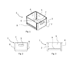
- FIG. 1, 2 and 3 there is shown a drawer 1 according to the present invention.
- It comprises a bottom wall 7 and skirt walls 2,4,5 and 6 extending in a manner substantially perpendicular to the bottom wall 7 and connected thereto and to each other to form a parallelepipedon lacking the top wall, thus creating an access aperture leading to the inner volume of the drawer 1.
- a front wall 2 fitted with a grip handle 3
- a back wall 4 facing the front wall 2
- the two walls 2 and 4 being connected to two side walls 5 and 6 on which the guides 8 and 9 are provided as one piece, which allow the drawer 1 to slide within the refrigerated cell, thus guiding the insertion/extraction motion thereof into/from the recess of the refrigerated cell.
- the bottom wall 7 extends horizontally and can therefore be moulded in an extremely simple and inexpensive manner.
- skirt walls 2,4,5 and 6 extend with no undercuts, so that they can be moulded without requiring the use of presses or moulds with moving parts, thus solving the problems suffered by the prior art.
- all the walls i.e. the bottom wall 7 as well as the skirt walls 2,4,5 and 6, are advantageously made as one piece and can be obtained in the same moulding step, so that the manufacturing process turns out to be extremely economical and fast.
- the front wall 2 comprises the handle 3 made as one piece, e.g. in the form of a recess obtained in the front wall 2 when moulding it.
- the side walls 5 and 6 are made in one piece with the guides 9 and 8, which comprise each two parallel tabs jutting out from the respective wall in a direction substantially perpendicular to the latter.
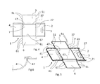
- the drawer 1 is subdivided into the various walls 2, 4, 5, 6 and 7, which can be turned upwards for the purpose of switching from the non-assembled configuration of Figs. 4 and 5 to the assembled configuration of Figs. 1, 2 e 3 .
- each skirt wall 2, 4, 5 and 6 can be bent with respect to the bottom wall 7 along one of its edges, so as to be overturned relative to the latter from a first position in which it lies substantially in the same plane (as in Figs. 4 and 5 ) to a second position in which it is perpendicular thereto (as in Figs. 1, 2 and 3 ).
- hinge edges 27, 47, 57 and 67 are provided which extend along the bottom wall 7 and, respectively, the front wall 2, the back wall 4 and the side walls 5 and 6.
- the hinge edges are advantageously obtained simply by reducing the section thickness at the bend, as shown in the sectional view of Fig. 6 that illustrates the hinge edge 47 between the wall 4 and the bottom 7.
- the edges of the skirt walls include fixing joints which advantageously eliminate the need to prearrange connection means such as screws, bolts, metal clips or the like, thus ensuring an extremely simple installation.
- the fixing joints comprise a plurality of engaging teeth 51, 61 and respective seats 21, 41 adapted to house the engaging teeth 51, 61 through mutual interference fit.
- the side walls 5 and 6 comprise engaging teeth 51, 61 that jut out from the free edge of the respective wall 5, 6 and extend substantially in the same plane as the latter, thus being complanate thereto.
- the seats 21, 41 are provided on the edges of the front wall 2 and of the back wall 4, so that a user wanting to assemble the drawer 1 starting from the situation of Fig. 4 will first have to rotate (by bending them) the two side walls 5 and 6 to bring them perpendicular to the bottom wall 7 and then rotate (by bending them) the front wall 2 and the back wall 7 to bring them also perpendicular to the bottom 7 and thus fit by interference the engaging teeth 51,61 into the respective seats 21,41.
- Fig. 5 there is shown an extremely advantageous feature of the drawer 1 according to the present invention.
- the side walls 5 and 6, the front wall 2 and the back wall 4 have the lower edge, i.e. the one hinged to the bottom wall 7, bent by approximately 90°, so that the edge between them and the bottom 7 becomes round.
- the front wall 2 and the back wall 4 In order to make round those edges which when the drawer 1 is in the assembled condition (as in Fig. 1 ) are vertical, the front wall 2 and the back wall 4 have their side edges (i.e. those facing the side walls 5 and 6) bent by approximately 90°.
- the material of the drawer 1 is preferably a material characterised by sufficient elasticity to allow the side walls to be bent with respect to the bottom wall while at the same time ensuring sufficient strength to avoid any damage during the bending step; said material may be, for example, polypropylene or even polyethylene.
- the rounded side edges may be provided only on the side walls 5,6 and be absent on the front wall 2 and back wall 4.
Landscapes
- Engineering & Computer Science (AREA)
- Chemical & Material Sciences (AREA)
- Combustion & Propulsion (AREA)
- Physics & Mathematics (AREA)
- Mechanical Engineering (AREA)
- Thermal Sciences (AREA)
- General Engineering & Computer Science (AREA)
- Drawers Of Furniture (AREA)
Abstract
The present invention relates to a drawer (1) for a refrigerating apparatus, comprising at least one bottom wall (7) and skirt walls (2,4,5,6) which can be positioned perpendicularly to said bottom wall (7), a grip handle (3) and at least two slide guides (8,9) for guiding said drawer into a recess of said refrigerating apparatus during an insertion/extraction step, wherein said skirt walls (2,4,5,6) can be overturned relative to said bottom wall (7), and wherein said grip handle (3) and said slide guides (8,9) are provided in one piece with the respective skirt walls (2,5,6).
Description
- The present invention relates to a drawer for a refrigerating apparatus, such as a refrigerator, a freezer or a refrigerator-freezer.
- In particular, the drawer of the present invention is one of those suitable for storing fresh foods, e.g. vegetables, fruits or the like, within a refrigerated cell of a refrigerator.
- Such drawers are normally located in the lower portion of the refrigerated cell, under a shelf secured to the cell walls and acting as a cover for the drawer itself.
- These drawers are typically made of plastic, and their container part is manufactured as one piece by moulding the plastic material into suitable moulds.
- A first drawback of this solution relates to the room taken by such drawers, the transportation of which requires adequate volumes.
- This implies a second drawback, mainly due to the fact that the drawer has normally such shapes that the moulding process requires the use of moulds fitted with punches and movable parts (often referred to as "mould movements") in order to make, in one moulding step, also the undercuts present in the container part, which constitute, for example, handles, guides or the like.
- The use of such moulds in the production process however involves the use of relatively complex moulding presses suitable for moving the various components of the mould. Moreover, compared to a traditional mould with no movable parts, this solution is more expensive and requires frequent maintenance and checks to avoid problems that would be reflected in the finished part.
- If one wants to use simple moulds with no movable parts, one possible solution is to make first the container part of the drawer (i.e. the bottom wall with the side walls) and then mount to the container part all necessary details, e.g. handle or guides.
- Although this solution solves the aforementioned problems, it is not optimal because requires additional assembly steps that are somewhat time-consuming.
- The present invention aims at overcoming these and other drawbacks by providing a drawer for refrigerating apparatuses and a process for manufacturing such a drawer.
- The present invention relates to a drawer for refrigerating apparatuses according to
claim 1. Another object of the present invention is a household refrigerating apparatus comprising such a drawer according to one or more of the appended claims. - The idea at the basis of the present invention is to provide a drawer wherein the skirt walls thereof can be overturned relative to the bottom wall and a drawer grip handle is preferably made in one piece with one of said skirt walls.
- According to an extremely advantageous feature, also the slide guides are made in one piece with the respective walls.
- The fact that the skirt walls (i.e. the front wall, the back wall and the two side walls) can be overturned relative to the bottom wall allows for a simplified manufacturing process, because in this case the drawer parts to be moulded have no undercuts (so that moulds with no movable parts can be used) and it is not necessary to mount afterwards details such as guides and grip handle.
- Further advantageous features will be set out in the appended claims.
- These features as well as further advantages of the present invention will become apparent from the following description of an embodiment thereof as shown in the annexed drawings, which are supplied by way of non-limiting example, wherein:
-
Fig. 1 shows a perspective view of the drawer according to the present invention in the assembled condition; -
Fig. 2 shows a front view of the drawer ofFig. 1 ; -
Fig. 3 shows a side view of the drawer ofFig. 1 ; -
Fig. 4 shows a plan view of the drawer ofFig. 1 in the non-assembled condition; -
Fig. 5 shows a perspective view of the drawer ofFig. 4 ; -
Fig. 6 shows a cross-section of a portion of the walls of the drawer ofFig. 1 . - Referring now to
Figs. 1, 2 and 3 , there is shown adrawer 1 according to the present invention. - It comprises a
bottom wall 7 andskirt walls bottom wall 7 and connected thereto and to each other to form a parallelepipedon lacking the top wall, thus creating an access aperture leading to the inner volume of thedrawer 1. - Between the
skirt walls front wall 2 fitted with agrip handle 3, aback wall 4 facing thefront wall 2, the twowalls side walls guides drawer 1 to slide within the refrigerated cell, thus guiding the insertion/extraction motion thereof into/from the recess of the refrigerated cell. - The
bottom wall 7 extends horizontally and can therefore be moulded in an extremely simple and inexpensive manner. - The
skirt walls - In this way, all the walls, i.e. the
bottom wall 7 as well as theskirt walls - The
front wall 2 comprises thehandle 3 made as one piece, e.g. in the form of a recess obtained in thefront wall 2 when moulding it. - The
side walls guides - Of course, it must be pointed out right away that different shapes of the
handle 3 andguides - In addition to handles and guides, it is also possible to provide on the
walls drawer 1. Such holes also ensure that the foodstuffs stored in thedrawer 1 are preserved at the proper temperature. - As can be seen in
Figs. 4 and 5 , thedrawer 1 is subdivided into thevarious walls Figs. 4 and 5 to the assembled configuration ofFigs. 1, 2 e 3 . - More specifically, each
skirt wall bottom wall 7 along one of its edges, so as to be overturned relative to the latter from a first position in which it lies substantially in the same plane (as inFigs. 4 and 5 ) to a second position in which it is perpendicular thereto (as inFigs. 1, 2 and 3 ). - To this end,
hinge edges bottom wall 7 and, respectively, thefront wall 2, theback wall 4 and theside walls - The hinge edges are advantageously obtained simply by reducing the section thickness at the bend, as shown in the sectional view of
Fig. 6 that illustrates thehinge edge 47 between thewall 4 and thebottom 7. - Furthermore, in order to facilitate the assembly, the edges of the skirt walls include fixing joints which advantageously eliminate the need to prearrange connection means such as screws, bolts, metal clips or the like, thus ensuring an extremely simple installation.
- The fixing joints comprise a plurality of
engaging teeth respective seats engaging teeth - More in detail, with reference to
Fig. 5 , it can be noted that theside walls engaging teeth respective wall - The
seats front wall 2 and of theback wall 4, so that a user wanting to assemble thedrawer 1 starting from the situation ofFig. 4 will first have to rotate (by bending them) the twoside walls bottom wall 7 and then rotate (by bending them) thefront wall 2 and theback wall 7 to bring them also perpendicular to thebottom 7 and thus fit by interference theengaging teeth respective seats - This extreme simplicity of assembly also brings about a further advantage inherent to the fact that it is possible to transport a large number of
drawers 1 without these taking up much space: in fact, it is sufficient to transport thedrawers 1 piled up in the non-assembled condition (as shown inFigs. 4 and 5 ), which may then be assembled only when necessary; this process, as described above, is so simple and fast that it may even be left up to the final user, who will need no special technical skills or tools. - Referring now more in detail to
Fig. 5 , there is shown an extremely advantageous feature of thedrawer 1 according to the present invention. - For the purpose of avoiding the presence of sharp edges, in fact, the latter have a rounded shape that makes them stronger and less dangerous in the event of an impact.
- To this end, the
side walls front wall 2 and theback wall 4 have the lower edge, i.e. the one hinged to thebottom wall 7, bent by approximately 90°, so that the edge between them and thebottom 7 becomes round. - In order to make round those edges which when the
drawer 1 is in the assembled condition (as inFig. 1 ) are vertical, thefront wall 2 and theback wall 4 have their side edges (i.e. those facing theside walls 5 and 6) bent by approximately 90°. - This provides two advantages: firstly, the vertical edges become round, and secondly, the
seats engaging teeth respective walls - Many changes may of course be made in the light of the teachings provided herein, which changes will nonetheless fall within the scope of the present invention.
- The material of the
drawer 1 is preferably a material characterised by sufficient elasticity to allow the side walls to be bent with respect to the bottom wall while at the same time ensuring sufficient strength to avoid any damage during the bending step; said material may be, for example, polypropylene or even polyethylene. - For example, the rounded side edges may be provided only on the
side walls front wall 2 andback wall 4. - Likewise, it is conceivable that the positions of the
seats engaging teeth side walls front wall 2 andback wall 4; in such a case, the bending of the side walls will take place following the bending of the front and back walls.
Claims (12)
- Drawer (1) for a refrigerating apparatus, comprising at least one bottom wall (7) and skirt walls (2,4,5,6) which can be positioned perpendicularly to said bottom wall (7), and a grip handle (3),
characterised in that
said skirt walls (2,4,5,6) can be overturned relative to said bottom wall (7), and wherein said grip handle (3) is provided in one piece with at least one of the skirt walls (2,5,6). - Drawer (1) according to claim 1, further comprising at least two slide guides (8,9) associated with as many skirt walls for guiding said drawer into a recess of said refrigerating apparatus during an insertion/extraction step, said slide guides (8,9) being provided in one piece with the respective skirt walls.
- Drawer (1) according to claim 1 or 2, wherein the skirt walls (2,4,5,6) and the bottom wall (7) are manufactured as one piece.
- Drawer (1) according to claim 1 or 2 or 3, wherein said bottom wall (7) and said skirt walls (2,4,5,6) have no undercuts.
- Drawer (1) according to any of the of the preceding claims, wherein said skirt walls (2,4,5,6) comprise a front wall (2) which incorporates said handle (3) in the form of a recess obtained in said front wall (2).
- Drawer (1) according to any one of the preceding claims, wherein said skirt walls (2,4,5,6) comprise two side walls (5,6) incorporating said guides (9,8), which jut out from the respective wall in a direction substantially perpendicular thereto.
- Drawer (1) according to one or more of the preceding claims, wherein said skirt walls (2,4,5,6) can be turned about hinge edges (27,47,57,67) relative to said bottom wall (7), so as to switch from a first configuration in which they are complanate to the latter to a second configuration in which they are perpendicular thereto.
- Drawer (1) according to one or more of the preceding claims, wherein said hinge edges (27,47,57,67) are obtained through a reduction in thickness of the respective wall.
- Drawer (1) according to one or more of the preceding claims, wherein said skirt walls (2,4,5,6) include fixing joints (21,41,51,61) for mutually securing said skirt walls (2,4,5,6), and wherein said fixing joints comprise a plurality of engaging teeth (51,61) and of respective seats (21,41) adapted to house said engaging teeth (51,61) through mutual interference fit, said engaging teeth (51,61) jutting out from the free edges of two side walls (5,6) and being complanate to the respective side walls (5,6).
- Drawer (1) according to one or more of the preceding claims, wherein said skirt walls (2,4,5,6) have the edge hinged to the bottom wall (7) and bent by approximately 90°, and wherein the side edges of said front wall (2) and back wall (4) are bent by approximately 90°.
- Drawer (1) according to one or more of the preceding claims, comprising one or more holes provided in said skirt walls (2,4,5,6) and/or in said bottom wall (7).
- Household refrigerating apparatus comprising a drawer (1) according to one or more of the preceding claims.
Applications Claiming Priority (1)
| Application Number | Priority Date | Filing Date | Title |
|---|---|---|---|
| IT000120A ITTO20100120A1 (en) | 2010-02-17 | 2010-02-17 | DRAWER FOR REFRIGERATION EQUIPMENT |
Publications (1)
| Publication Number | Publication Date |
|---|---|
| EP2357438A1 true EP2357438A1 (en) | 2011-08-17 |
Family
ID=43569314
Family Applications (1)
| Application Number | Title | Priority Date | Filing Date |
|---|---|---|---|
| EP11154573A Withdrawn EP2357438A1 (en) | 2010-02-17 | 2011-02-15 | Drawer for refrigerating apparatuses |
Country Status (2)
| Country | Link |
|---|---|
| EP (1) | EP2357438A1 (en) |
| IT (1) | ITTO20100120A1 (en) |
Cited By (3)
| Publication number | Priority date | Publication date | Assignee | Title |
|---|---|---|---|---|
| CN102609011A (en) * | 2012-03-21 | 2012-07-25 | 山东理工大学 | Gas regulation control method of spontaneous modified atmosphere storage for fruit and vegetable preservation |
| CN102967115A (en) * | 2012-12-17 | 2013-03-13 | 合肥美的荣事达电冰箱有限公司 | Automatic sliding-in structure of refrigerator drawer |
| DE102014211332A1 (en) * | 2014-06-13 | 2015-12-17 | BSH Hausgeräte GmbH | Refrigerating appliance and drawer with pivoting wall elements for it |
Citations (8)
| Publication number | Priority date | Publication date | Assignee | Title |
|---|---|---|---|---|
| GB321420A (en) * | 1928-05-08 | 1929-11-08 | Doehler Die Casting Co | Improvements in collapsible drawers |
| US2276374A (en) * | 1939-07-14 | 1942-03-17 | Derman Harry | Collapsible drawer |
| JPS61175883U (en) * | 1985-04-23 | 1986-11-01 | ||
| DE3721372A1 (en) * | 1987-06-29 | 1987-10-29 | Frohmut Menze | Variable, collapsible and folded filing system with a press stud mechanism which is riveted in |
| JP2000130923A (en) * | 1998-10-23 | 2000-05-12 | Chiyoda Integre Co Ltd | Opening / cooling box |
| JP2002062033A (en) * | 2000-08-11 | 2002-02-28 | Fujitsu General Ltd | Assembling cold storage |
| US20080245802A1 (en) * | 2007-04-04 | 2008-10-09 | Gray William R | Drain pan assembly |
| WO2009046570A1 (en) * | 2007-10-10 | 2009-04-16 | Luhao Leng | Foldable drawer |
-
2010
- 2010-02-17 IT IT000120A patent/ITTO20100120A1/en unknown
-
2011
- 2011-02-15 EP EP11154573A patent/EP2357438A1/en not_active Withdrawn
Patent Citations (8)
| Publication number | Priority date | Publication date | Assignee | Title |
|---|---|---|---|---|
| GB321420A (en) * | 1928-05-08 | 1929-11-08 | Doehler Die Casting Co | Improvements in collapsible drawers |
| US2276374A (en) * | 1939-07-14 | 1942-03-17 | Derman Harry | Collapsible drawer |
| JPS61175883U (en) * | 1985-04-23 | 1986-11-01 | ||
| DE3721372A1 (en) * | 1987-06-29 | 1987-10-29 | Frohmut Menze | Variable, collapsible and folded filing system with a press stud mechanism which is riveted in |
| JP2000130923A (en) * | 1998-10-23 | 2000-05-12 | Chiyoda Integre Co Ltd | Opening / cooling box |
| JP2002062033A (en) * | 2000-08-11 | 2002-02-28 | Fujitsu General Ltd | Assembling cold storage |
| US20080245802A1 (en) * | 2007-04-04 | 2008-10-09 | Gray William R | Drain pan assembly |
| WO2009046570A1 (en) * | 2007-10-10 | 2009-04-16 | Luhao Leng | Foldable drawer |
Cited By (4)
| Publication number | Priority date | Publication date | Assignee | Title |
|---|---|---|---|---|
| CN102609011A (en) * | 2012-03-21 | 2012-07-25 | 山东理工大学 | Gas regulation control method of spontaneous modified atmosphere storage for fruit and vegetable preservation |
| CN102609011B (en) * | 2012-03-21 | 2014-08-06 | 山东理工大学 | Gas regulation control method of spontaneous modified atmosphere storage for fruit and vegetable preservation |
| CN102967115A (en) * | 2012-12-17 | 2013-03-13 | 合肥美的荣事达电冰箱有限公司 | Automatic sliding-in structure of refrigerator drawer |
| DE102014211332A1 (en) * | 2014-06-13 | 2015-12-17 | BSH Hausgeräte GmbH | Refrigerating appliance and drawer with pivoting wall elements for it |
Also Published As
| Publication number | Publication date |
|---|---|
| ITTO20100120A1 (en) | 2011-08-18 |
Similar Documents
| Publication | Publication Date | Title |
|---|---|---|
| US5486046A (en) | Cantilever slide out refrigerator shelf | |
| US8616665B2 (en) | Door bin for a domestic refrigerator | |
| EP2549212B1 (en) | Refrigerator | |
| US9574820B2 (en) | Variable shelf apparatus and refrigerator having the same | |
| US8328302B2 (en) | Refrigerator drawer and refrigerator having the same | |
| US9702614B2 (en) | Refrigerator | |
| EP2581694B1 (en) | Refrigerator | |
| US8511767B2 (en) | Multi-piece basket assembly for a consumer appliance | |
| US9207011B2 (en) | Food container and refrigerator having the same | |
| US8794722B2 (en) | Drawer assembly for an appliance | |
| US10495373B2 (en) | Refrigerator | |
| US20170066566A1 (en) | Container and Storage System | |
| USD947256S1 (en) | Door for entryway with refrigerator and delivery storage box | |
| US20080054772A1 (en) | Support assembly for an appliance storage bin or storage shelf | |
| US7665814B2 (en) | Cold goods container for a cooling apparatus | |
| US20210401174A1 (en) | Trim assembly for an appliance shelf | |
| US9554648B2 (en) | Sliding system for drawer | |
| EP2933405A1 (en) | Door handle and refrigerator having the same | |
| US20120146480A1 (en) | Multi-material basket for refrigerator or freezer | |
| US9513047B2 (en) | Door module assembly for a refrigerator appliance | |
| EP2401569B1 (en) | Basket kick-out | |
| US10240858B2 (en) | Home appliance having drawer-type movable container with a handle | |
| KR102860950B1 (en) | Refrigerator | |
| US9823012B2 (en) | Storage assembly for an appliance | |
| WO2016134987A1 (en) | Refrigerating apparatus comprising a support panel |
Legal Events
| Date | Code | Title | Description |
|---|---|---|---|
| PUAI | Public reference made under article 153(3) epc to a published international application that has entered the european phase |
Free format text: ORIGINAL CODE: 0009012 |
|
| AK | Designated contracting states |
Kind code of ref document: A1 Designated state(s): AL AT BE BG CH CY CZ DE DK EE ES FI FR GB GR HR HU IE IS IT LI LT LU LV MC MK MT NL NO PL PT RO RS SE SI SK SM TR |
|
| AX | Request for extension of the european patent |
Extension state: BA ME |
|
| 17P | Request for examination filed |
Effective date: 20120215 |
|
| STAA | Information on the status of an ep patent application or granted ep patent |
Free format text: STATUS: THE APPLICATION IS DEEMED TO BE WITHDRAWN |
|
| 18D | Application deemed to be withdrawn |
Effective date: 20130829 |