EP2357372A1 - bearing with rolling elements with different diameter - Google Patents
bearing with rolling elements with different diameter Download PDFInfo
- Publication number
- EP2357372A1 EP2357372A1 EP11151499A EP11151499A EP2357372A1 EP 2357372 A1 EP2357372 A1 EP 2357372A1 EP 11151499 A EP11151499 A EP 11151499A EP 11151499 A EP11151499 A EP 11151499A EP 2357372 A1 EP2357372 A1 EP 2357372A1
- Authority
- EP
- European Patent Office
- Prior art keywords
- race
- control element
- rolling elements
- elements
- remaining
- Prior art date
- Legal status (The legal status is an assumption and is not a legal conclusion. Google has not performed a legal analysis and makes no representation as to the accuracy of the status listed.)
- Granted
Links
- 238000005096 rolling process Methods 0.000 title claims abstract description 101
- 230000002829 reductive effect Effects 0.000 claims description 4
- 238000006073 displacement reaction Methods 0.000 claims description 3
- 239000004519 grease Substances 0.000 description 5
- 230000006866 deterioration Effects 0.000 description 3
- 238000000926 separation method Methods 0.000 description 3
- 239000000919 ceramic Substances 0.000 description 2
- 230000007797 corrosion Effects 0.000 description 2
- 238000005260 corrosion Methods 0.000 description 2
- 230000003247 decreasing effect Effects 0.000 description 2
- 230000000694 effects Effects 0.000 description 2
- 239000000463 material Substances 0.000 description 2
- 229910000831 Steel Inorganic materials 0.000 description 1
- 239000002199 base oil Substances 0.000 description 1
- 230000001351 cycling effect Effects 0.000 description 1
- 230000001419 dependent effect Effects 0.000 description 1
- 239000000975 dye Substances 0.000 description 1
- 230000002401 inhibitory effect Effects 0.000 description 1
- 230000001788 irregular Effects 0.000 description 1
- 238000004519 manufacturing process Methods 0.000 description 1
- 239000002184 metal Substances 0.000 description 1
- 230000003647 oxidation Effects 0.000 description 1
- 238000007254 oxidation reaction Methods 0.000 description 1
- 230000036961 partial effect Effects 0.000 description 1
- 150000003839 salts Chemical class 0.000 description 1
- 239000010959 steel Substances 0.000 description 1
Images

Classifications
-
- F—MECHANICAL ENGINEERING; LIGHTING; HEATING; WEAPONS; BLASTING
- F16—ENGINEERING ELEMENTS AND UNITS; GENERAL MEASURES FOR PRODUCING AND MAINTAINING EFFECTIVE FUNCTIONING OF MACHINES OR INSTALLATIONS; THERMAL INSULATION IN GENERAL
- F16C—SHAFTS; FLEXIBLE SHAFTS; ELEMENTS OR CRANKSHAFT MECHANISMS; ROTARY BODIES OTHER THAN GEARING ELEMENTS; BEARINGS
- F16C19/00—Bearings with rolling contact, for exclusively rotary movement
- F16C19/02—Bearings with rolling contact, for exclusively rotary movement with bearing balls essentially of the same size in one or more circular rows
- F16C19/20—Bearings with rolling contact, for exclusively rotary movement with bearing balls essentially of the same size in one or more circular rows with loose spacing bodies, e.g. balls, between the bearing balls
-
- F—MECHANICAL ENGINEERING; LIGHTING; HEATING; WEAPONS; BLASTING
- F01—MACHINES OR ENGINES IN GENERAL; ENGINE PLANTS IN GENERAL; STEAM ENGINES
- F01D—NON-POSITIVE DISPLACEMENT MACHINES OR ENGINES, e.g. STEAM TURBINES
- F01D25/00—Component parts, details, or accessories, not provided for in, or of interest apart from, other groups
- F01D25/16—Arrangement of bearings; Supporting or mounting bearings in casings
-
- F—MECHANICAL ENGINEERING; LIGHTING; HEATING; WEAPONS; BLASTING
- F02—COMBUSTION ENGINES; HOT-GAS OR COMBUSTION-PRODUCT ENGINE PLANTS
- F02C—GAS-TURBINE PLANTS; AIR INTAKES FOR JET-PROPULSION PLANTS; CONTROLLING FUEL SUPPLY IN AIR-BREATHING JET-PROPULSION PLANTS
- F02C7/00—Features, components parts, details or accessories, not provided for in, or of interest apart form groups F02C1/00 - F02C6/00; Air intakes for jet-propulsion plants
- F02C7/06—Arrangements of bearings; Lubricating
-
- F—MECHANICAL ENGINEERING; LIGHTING; HEATING; WEAPONS; BLASTING
- F16—ENGINEERING ELEMENTS AND UNITS; GENERAL MEASURES FOR PRODUCING AND MAINTAINING EFFECTIVE FUNCTIONING OF MACHINES OR INSTALLATIONS; THERMAL INSULATION IN GENERAL
- F16C—SHAFTS; FLEXIBLE SHAFTS; ELEMENTS OR CRANKSHAFT MECHANISMS; ROTARY BODIES OTHER THAN GEARING ELEMENTS; BEARINGS
- F16C19/00—Bearings with rolling contact, for exclusively rotary movement
- F16C19/02—Bearings with rolling contact, for exclusively rotary movement with bearing balls essentially of the same size in one or more circular rows
-
- F—MECHANICAL ENGINEERING; LIGHTING; HEATING; WEAPONS; BLASTING
- F16—ENGINEERING ELEMENTS AND UNITS; GENERAL MEASURES FOR PRODUCING AND MAINTAINING EFFECTIVE FUNCTIONING OF MACHINES OR INSTALLATIONS; THERMAL INSULATION IN GENERAL
- F16C—SHAFTS; FLEXIBLE SHAFTS; ELEMENTS OR CRANKSHAFT MECHANISMS; ROTARY BODIES OTHER THAN GEARING ELEMENTS; BEARINGS
- F16C19/00—Bearings with rolling contact, for exclusively rotary movement
- F16C19/22—Bearings with rolling contact, for exclusively rotary movement with bearing rollers essentially of the same size in one or more circular rows, e.g. needle bearings
-
- F—MECHANICAL ENGINEERING; LIGHTING; HEATING; WEAPONS; BLASTING
- F16—ENGINEERING ELEMENTS AND UNITS; GENERAL MEASURES FOR PRODUCING AND MAINTAINING EFFECTIVE FUNCTIONING OF MACHINES OR INSTALLATIONS; THERMAL INSULATION IN GENERAL
- F16C—SHAFTS; FLEXIBLE SHAFTS; ELEMENTS OR CRANKSHAFT MECHANISMS; ROTARY BODIES OTHER THAN GEARING ELEMENTS; BEARINGS
- F16C19/00—Bearings with rolling contact, for exclusively rotary movement
- F16C19/50—Other types of ball or roller bearings
- F16C19/505—Other types of ball or roller bearings with the diameter of the rolling elements of one row differing from the diameter of those of another row
-
- F—MECHANICAL ENGINEERING; LIGHTING; HEATING; WEAPONS; BLASTING
- F16—ENGINEERING ELEMENTS AND UNITS; GENERAL MEASURES FOR PRODUCING AND MAINTAINING EFFECTIVE FUNCTIONING OF MACHINES OR INSTALLATIONS; THERMAL INSULATION IN GENERAL
- F16C—SHAFTS; FLEXIBLE SHAFTS; ELEMENTS OR CRANKSHAFT MECHANISMS; ROTARY BODIES OTHER THAN GEARING ELEMENTS; BEARINGS
- F16C33/00—Parts of bearings; Special methods for making bearings or parts thereof
- F16C33/30—Parts of ball or roller bearings
- F16C33/306—Means to synchronise movements
-
- F—MECHANICAL ENGINEERING; LIGHTING; HEATING; WEAPONS; BLASTING
- F16—ENGINEERING ELEMENTS AND UNITS; GENERAL MEASURES FOR PRODUCING AND MAINTAINING EFFECTIVE FUNCTIONING OF MACHINES OR INSTALLATIONS; THERMAL INSULATION IN GENERAL
- F16C—SHAFTS; FLEXIBLE SHAFTS; ELEMENTS OR CRANKSHAFT MECHANISMS; ROTARY BODIES OTHER THAN GEARING ELEMENTS; BEARINGS
- F16C33/00—Parts of bearings; Special methods for making bearings or parts thereof
- F16C33/30—Parts of ball or roller bearings
- F16C33/32—Balls
-
- F—MECHANICAL ENGINEERING; LIGHTING; HEATING; WEAPONS; BLASTING
- F16—ENGINEERING ELEMENTS AND UNITS; GENERAL MEASURES FOR PRODUCING AND MAINTAINING EFFECTIVE FUNCTIONING OF MACHINES OR INSTALLATIONS; THERMAL INSULATION IN GENERAL
- F16C—SHAFTS; FLEXIBLE SHAFTS; ELEMENTS OR CRANKSHAFT MECHANISMS; ROTARY BODIES OTHER THAN GEARING ELEMENTS; BEARINGS
- F16C33/00—Parts of bearings; Special methods for making bearings or parts thereof
- F16C33/30—Parts of ball or roller bearings
- F16C33/34—Rollers; Needles
-
- F—MECHANICAL ENGINEERING; LIGHTING; HEATING; WEAPONS; BLASTING
- F16—ENGINEERING ELEMENTS AND UNITS; GENERAL MEASURES FOR PRODUCING AND MAINTAINING EFFECTIVE FUNCTIONING OF MACHINES OR INSTALLATIONS; THERMAL INSULATION IN GENERAL
- F16C—SHAFTS; FLEXIBLE SHAFTS; ELEMENTS OR CRANKSHAFT MECHANISMS; ROTARY BODIES OTHER THAN GEARING ELEMENTS; BEARINGS
- F16C41/00—Other accessories, e.g. devices integrated in the bearing not relating to the bearing function as such
- F16C41/008—Identification means, e.g. markings, RFID-tags; Data transfer means
-
- F—MECHANICAL ENGINEERING; LIGHTING; HEATING; WEAPONS; BLASTING
- F16—ENGINEERING ELEMENTS AND UNITS; GENERAL MEASURES FOR PRODUCING AND MAINTAINING EFFECTIVE FUNCTIONING OF MACHINES OR INSTALLATIONS; THERMAL INSULATION IN GENERAL
- F16C—SHAFTS; FLEXIBLE SHAFTS; ELEMENTS OR CRANKSHAFT MECHANISMS; ROTARY BODIES OTHER THAN GEARING ELEMENTS; BEARINGS
- F16C2300/00—Application independent of particular apparatuses
- F16C2300/10—Application independent of particular apparatuses related to size
- F16C2300/14—Large applications, e.g. bearings having an inner diameter exceeding 500 mm
-
- F—MECHANICAL ENGINEERING; LIGHTING; HEATING; WEAPONS; BLASTING
- F16—ENGINEERING ELEMENTS AND UNITS; GENERAL MEASURES FOR PRODUCING AND MAINTAINING EFFECTIVE FUNCTIONING OF MACHINES OR INSTALLATIONS; THERMAL INSULATION IN GENERAL
- F16C—SHAFTS; FLEXIBLE SHAFTS; ELEMENTS OR CRANKSHAFT MECHANISMS; ROTARY BODIES OTHER THAN GEARING ELEMENTS; BEARINGS
- F16C2360/00—Engines or pumps
- F16C2360/23—Gas turbine engines
Definitions
- This invention relates to a bearing, and is particularly, but not exclusively, concerned with a bearing for a rotatable nozzle of a gas turbine engine.
- large bearings such as slewing bearings used on rotatable nozzles for gas turbine engines, are typically of a deep groove design to ensure that the rolling elements remain in contact with the races of the bearing when subjected to loads at various angles during operation. These characteristics mean that it is often not practical to use a cage arrangement to maintain spacing between the rolling elements. Separation of the rolling elements is therefore maintained using individual separator elements disposed between the rolling elements so that the separator elements are free to move with the rolling elements about the bearing.
- the increased friction between the rolling elements and the separator elements can cause local and instantaneous flash temperatures which, in the case of greased bearings, lead to deterioration of the grease.
- Gross deterioration of the grease can lead to separation of the base-oil, oxidation of the grease or a change in consistency making the bearing more sensitive to friction.
- Deterioration of the grease can also reduce the corrosion inhibiting properties of the grease, leaving the bearing exposed to corrosion.
- a bearing comprising a plurality of rolling elements disposed between a first race and a second race, in which at least one of the rolling elements is a control element having characteristics which differ from the remaining rolling elements such that rotation of the first race with respect to the second race causes the control element to travel at a precessional speed which is greater than or less than the precessional speed of the remaining rolling elements.
- the precessional speed of the rolling element is the speed at which the centre of a rolling element is driven in a circumferential direction around the bearing.
- the control element may have a characteristic which causes the control element to rotate faster or slower than the remaining rolling elements when the first race is rotated with respect to the second race.
- the control element may have a different rolling radius from the remaining rolling elements.
- the control element may be of a different shape or size from the remaining rolling elements.
- the control element may have a non-circular profile.
- the control element may, for example, have a polygonal profile.
- the control element may have an elliptical profile.
- the control element has an irregular profile.
- the control element may be one of a plurality of identical control elements. There may be 1, 2 or more than 2 control elements.
- the ratio of control elements to remaining elements may be not greater than 1:1 and not less than 1:10. Preferably the ratio of control elements to remaining elements may be not less than 1:100.
- the number of control elements may therefore equal the number of remaining rolling elements. It will be appreciated, however, that the ratio of control elements to the remaining elements may be determined based on the loading requirements of the bearing and the number of control elements required to maintain separation of the rolling elements.
- the remaining rolling elements may be support elements.
- the rolling elements may be spherical.
- the raceways of the first race and the second race may have raceway curvatures which correspond to the curvature of the rolling elements.
- the raceway curvatures may be curved to correspond to the curvature of the rolling elements such that the distance between the first race and the second race in the region of contact with the control element is reduced.
- the diameter of the support elements may be greater than the diameter of the control elements such that the distance between the first race and the second race in the region of contact with the control element is increased.
- the contact angle of the control element may be greater than the contact angle of the remaining rolling elements, or the contact angle of the control element may be less than the contact angle of the remaining rolling elements.
- the first race may be an inner race and the second race may be an outer race and in one embodiment displacement of the first race towards the second race causes the control element to contact the inner race at a position which is radially outward of the position at which the remaining elements contact the inner race, and for the control element to contact the outer race at a position which is radially inward of the position at which the remaining elements contact the outer race.
- displacement of the first race towards the second race causes the control element to contact the inner race at a position which is radially inward of the position at which the remaining elements contact the inner race, and for the control element to contact the outer race at a position which is radially outward of the position at which the remaining elements contact the outer race.
- the stiffness of the control element may be less than the stiffness of the remaining rolling elements.
- stiffness is taken to mean resistance to deflection of the rolling element normal to the raceway surface.
- the stiffness of the control element may be greater than the stiffness of the remaining rolling elements.
- the coefficient of thermal expansion of the control element may be different from the coefficient of thermal expansion of the remaining rolling elements.
- the coefficient of thermal expansion of the control element may be less than that of the remaining rolling elements.
- the frictional resistance of the control element to precessional speed may be different to the frictional resistance of the remaining rolling elements to precessional speed.
- a rotatable nozzle for a gas turbine engine may be provided with a bearing according to the above.
- the bearing 2, shown in Figures 1 and 2 comprises a plurality of spherical rolling elements 8, 10 disposed between an inner race 4 and an outer race 6. Separator element elements 12 are provided between adjacent rolling elements 8, 10.
- the rolling elements 8,10 consist of support elements 8 and control elements 10.
- Each control element 10 is disposed between two adjacent support elements 8.
- the control elements 10 are substantially the same size and are smaller than the support elements 8.
- the races 4, 6 are thus predominantly supported by the larger support elements 8.
- the ratio of control elements 10 to support elements 8 may, for example, be 1:7.
- the inner and outer races 4, 6 have respective raceways 14, 16 which are curved to accommodate the rolling elements 8, 10.
- the curvature of the raceways 14, 16 corresponds to the curvature of the rolling elements 8, 10 and together, the raceways 14, 16 extend almost completely about the rolling elements 8, 10. The curvature of the raceways 14, 16 thus ensures that the rolling elements 8, 10 remain in contact with the raceways 14, 16 over a range of operating conditions.
- Figure 4 shows a sectional view of the bearing 2 through the support element 8 in which the bearing is subjected to axial and radial loading.
- the support element 8 is in contact with both the inner raceway 14 and the outer raceway 16.
- the point of contact with the inner raceway 14 is diametrically opposite, with respect to the support element 8, the point of contact with the outer raceway 16.
- the radial position at which the support element 8 contacts the inner raceway 14 and the outer raceway 16 is dependent on the interference load acting on the support element 8, where the interference load is the amount of load transmitted from the raceways 4,6 to the rolling elements 8,10.
- the angle formed by a line intersecting the contact points with the radial direction of the bearing 2 is the contact angle of the support element 8.
- Figure 5 shows a sectional view of the bearing 2 through the control element 10 in which the bearing is subjected to the same axial and radial loading shown in Figure 4 .
- the interference load which acts on the control element 10 is smaller than that which acts on the support element 8. Consequently, the control element 10 contacts the outer raceway at a point which is radially inward of the corresponding contact point of the support element 8 and contacts the inner raceway 14 at a point which is radially outward of the corresponding contact point of the support element 8.
- the contact angle of the control element 10 is thus greater than the contact angle of the support element 8.
- Rotation of the inner race 4 with respect to the outer race 6 drives the rolling elements 8, 10 about outer raceway 16 of the bearing 2.
- the speed at which the centre of a rolling element 8, 10 is driven in a circumferential direction around the bearing is the precessional speed of the rolling element 8, 10.
- the control element 10 which is driven by the inner raceway 14 at a distance which is radially outward from the point of contact between the support elements 8 and the inner raceway 14, is driven at a higher precessional speed than the support element 8. Furthermore, the control element 10 is driven about the outer raceway 16 at a distance that is radially inward from the support elements 8 and the outer raceway 16. The control element 10 thus travels over a shorter distance about the outer raceway 16 than a corresponding support element 8.
- the control element 10 is therefore driven at a higher rotational speed over a shorter distance than a corresponding support element 8 which translates into a higher precessional speed.
- control element 10 is thus driven up behind an adjacent support element 8 and creates a gap between the control element 10 and a following support element 8.
- the rolling elements 8, 10 are thus divided up into trains of support elements 8 disposed between control elements 10.
- the interference load which acts on the control element 10 may be arranged such that it is greater than that which acts on the support element 8, for example where the control element 10 has a larger rolling diameter than the support elements 8. Consequently, the control element 10 contacts the outer raceway at a point which is radially outward of the corresponding contact point of the support element 8 and contacts the inner raceway 14 at a point which is radially inward of the corresponding contact point of the support element 8.
- the contact angle of the control element 10 is thus smaller than the contact angle of the support element 8.
- the control element 10 is driven at a lower rotational speed over a shorter distance than a corresponding support element 8 which translates into a lower precessional speed.
- the control element 10 is slowed down in front of an adjacent support element 8 and creates a gap between the control element 10 and a leading support element 8.
- the rolling elements 8, 10 are thus divided up into trains of support elements 8 disposed between control elements 10.
- the control elements 10 may be a different colour from the support elements 8 which enables the control elements 10 to be visibly distinguished from the support elements 8.
- the rolling elements 8, 10 are ceramic
- different coloured dyes e.g comprising a trace level of metal salt
- the control elements 10 may, however, be made from a material which is visibly different from the material from which the support elements 8 are made.
- either the support elements 8 or the control elements10 could be made from steel and the other made from ceramic.
- control element is made the same size as the support element, but has a lower stiffness.
- the control element when the bearing is loaded, the control element is compressed to a smaller rolling diameter than the support element. The rolling diameter of the control element is thus reduced when the bearing is placed under a load which is large enough to deform the control element.
- the relative youngs modulus of the control element and raceway is chosen such that the profile of the control element is altered as the load upon the bearing is varied.
- the contact area between the rolling element and raceway is altered to vary the stiffness of the control element. For example, as the load is increased, contact area between the rolling element and raceway is increased, the stiffness of the control element is increased. As the load is decreased, contact area between the rolling element and raceway is decreased, the stiffness of the control element is reduced.
- the rolling radius will be a function of the non-deformed element radius 20 and a radius 22 from the centre of the element to the deformed surface 24 of the element.
- the maximum rolling radius is the radius of the element 20 and the minimum rolling radius is the element radius 20 minus the element deflection (i.e. the deformed radius 22)
- control element is provided with a lower thermal expansion.
- the control element therefore acts as a control element when the temperature of the bearing is raised to expand the control elements and the support elements. This may be particularly suitable for bearings operating over large temperature ranges such as engine nozzle bearings.
- the frictional resistance of the control element to precessional speed may be different to the frictional resistance of the remaining rolling elements to precessional speed.
- the effective rolling diameter of the control element is changed (i.e. the control element is elastically deformed) at a contact region between the control element and raceway by the frictional resistance to precessional speed.
- a control element with a lower frictional resistance than the remaining rolling elements would have a greater precessional speed than the rolling elements.
- a control element with a higher frictional resistance than the remaining rolling elements would have a lower precessional speed than the rolling elements.
- Figures 8b, 8c and 8d each with a different geometric profile on the element rolling surface, as indicated in Figure 8a.
- Figure 8b shows a semi-crowned profile, which will minimise the maximum Hertzian stresses at the contact region. It comprises central cylindrical section flanked by two large radii sides to minimise the stress at the edges of the roller.
- a variation of this is a fully crowned profile shown in Figure 8c and a barrelled profile in Figure 8d , which will produce the same effect.
- the variation in radius along the length of rolling element i.e. from left to right in Figures 8b, 8c and 8d ) which forms the semi-crowned or crowned profile may be a small percentage of the total diameter.
- Such geometric profiles will result in a different deflection into the raceway, thus a different rolling radius and a different precession speed.
- bearings comprising other types of rolling elements. These include, but are not limited to, roller bearings, taper bearings and needle bearings.
- the invention may be applied to caged bearings to change the distribution of the net load exerted on the cage by the rolling elements. This may allow use of a cage which is lower weight or smaller than would otherwise be required, or reduce cycling loading and enhance the durability of the cage.
Landscapes
- Engineering & Computer Science (AREA)
- General Engineering & Computer Science (AREA)
- Mechanical Engineering (AREA)
- Chemical & Material Sciences (AREA)
- Combustion & Propulsion (AREA)
- Rolling Contact Bearings (AREA)
Abstract
Description
- This invention relates to a bearing, and is particularly, but not exclusively, concerned with a bearing for a rotatable nozzle of a gas turbine engine.
- Bearings which have a large track diameter in relation to the diameter of the rolling elements, require a large number of rolling elements. In addition, large bearings, such as slewing bearings used on rotatable nozzles for gas turbine engines, are typically of a deep groove design to ensure that the rolling elements remain in contact with the races of the bearing when subjected to loads at various angles during operation. These characteristics mean that it is often not practical to use a cage arrangement to maintain spacing between the rolling elements. Separation of the rolling elements is therefore maintained using individual separator elements disposed between the rolling elements so that the separator elements are free to move with the rolling elements about the bearing.
- For large diameter bearings it is necessary to ensure effective distribution of the load applied to the bearing across the rolling elements to avoid exposing individual elements to excessive loads. The rolling elements are therefore manufactured to extremely tight tolerances. A consequence of manufacturing the rolling elements to tight tolerances is that the performance of the rolling elements in the bearing is extremely consistent. A phenomenon associated with this consistent performance is the tendency for the rolling elements, and associated separator element elements, to group together into a continuous train with only a single gap in the train between the rolling elements and the separator elements.
- Large uninterrupted trains of rolling elements and separator elements increase the compressive loads between rolling elements and separator elements and drive friction forces between the rolling elements and the separator elements higher. This, in turn, increases the amount of torque required to rotate the bearing.
- In addition, the increased friction between the rolling elements and the separator elements can cause local and instantaneous flash temperatures which, in the case of greased bearings, lead to deterioration of the grease. Gross deterioration of the grease can lead to separation of the base-oil, oxidation of the grease or a change in consistency making the bearing more sensitive to friction. Deterioration of the grease can also reduce the corrosion inhibiting properties of the grease, leaving the bearing exposed to corrosion.
- High levels of friction can also give rise to an increase in bearing noise.
- In this specification, the terms "radial" and "axial" are defined with respect to the radius of the bearing and the rotational axis of the bearing unless otherwise specified.
- According to the invention there is provided a bearing comprising a plurality of rolling elements disposed between a first race and a second race, in which at least one of the rolling elements is a control element having characteristics which differ from the remaining rolling elements such that rotation of the first race with respect to the second race causes the control element to travel at a precessional speed which is greater than or less than the precessional speed of the remaining rolling elements.
- The precessional speed of the rolling element is the speed at which the centre of a rolling element is driven in a circumferential direction around the bearing.
- The control element may have a characteristic which causes the control element to rotate faster or slower than the remaining rolling elements when the first race is rotated with respect to the second race.
- The control element may have a different rolling radius from the remaining rolling elements.
- The control element may be of a different shape or size from the remaining rolling elements. For example, the control element may have a non-circular profile. The control element may, for example, have a polygonal profile. Alternatively the control element may have an elliptical profile. Alternatively the control element has an irregular profile.
- The control element may be one of a plurality of identical control elements. There may be 1, 2 or more than 2 control elements. The ratio of control elements to remaining elements may be not greater than 1:1 and not less than 1:10. Preferably the ratio of control elements to remaining elements may be not less than 1:100. The number of control elements may therefore equal the number of remaining rolling elements. It will be appreciated, however, that the ratio of control elements to the remaining elements may be determined based on the loading requirements of the bearing and the number of control elements required to maintain separation of the rolling elements.
- The remaining rolling elements may be support elements.
- The rolling elements may be spherical. The raceways of the first race and the second race may have raceway curvatures which correspond to the curvature of the rolling elements. The raceway curvatures may be curved to correspond to the curvature of the rolling elements such that the distance between the first race and the second race in the region of contact with the control element is reduced. Alternatively the diameter of the support elements may be greater than the diameter of the control elements such that the distance between the first race and the second race in the region of contact with the control element is increased. The contact angle of the control element may be greater than the contact angle of the remaining rolling elements, or the contact angle of the control element may be less than the contact angle of the remaining rolling elements.
- The first race may be an inner race and the second race may be an outer race and in one embodiment displacement of the first race towards the second race causes the control element to contact the inner race at a position which is radially outward of the position at which the remaining elements contact the inner race, and for the control element to contact the outer race at a position which is radially inward of the position at which the remaining elements contact the outer race.
- In an alternative embodiment, displacement of the first race towards the second race causes the control element to contact the inner race at a position which is radially inward of the position at which the remaining elements contact the inner race, and for the control element to contact the outer race at a position which is radially outward of the position at which the remaining elements contact the outer race.
- The stiffness of the control element may be less than the stiffness of the remaining rolling elements. In this context, "stiffness" is taken to mean resistance to deflection of the rolling element normal to the raceway surface.
- The stiffness of the control element may be greater than the stiffness of the remaining rolling elements.
- The coefficient of thermal expansion of the control element may be different from the coefficient of thermal expansion of the remaining rolling elements. For example, the coefficient of thermal expansion of the control element may be less than that of the remaining rolling elements.
- The frictional resistance of the control element to precessional speed may be different to the frictional resistance of the remaining rolling elements to precessional speed.
- A rotatable nozzle for a gas turbine engine may be provided with a bearing according to the above.
- For a better understanding of the present invention, and to show more clearly how it may be carried into effect, reference will now be made, by way of example, to the accompanying drawings, in which:-
-
Figure 1 shows a schematic view of a large diameter bearing in accordance with the invention; -
Figure 2 shows an enlarged schematic partial view of the bearing shown inFigure 1 ; -
Figure 3 shows an enlarged sectional view along the line A-A of the bearing shown inFigures 1 and 2 ; -
Figure 4 shows a sectional view of the bearing through a support element of the bearing; -
Figure 5 shows a sectional view of the bearing through a control element of the bearing; -
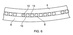
Figure 6 shows a schematic representation of an embodiment of the invention, -
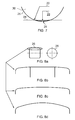
Figure 7 shows a schematic representation of an embodiment of the invention as it deforms in use; and -
Figure 8 shows a number of variations to the geometry of the rolling element of the present invention. - The
bearing 2, shown inFigures 1 and 2 , comprises a plurality of sphericalrolling elements inner race 4 and anouter race 6.Separator element elements 12 are provided between adjacentrolling elements rolling elements support elements 8 andcontrol elements 10. Eachcontrol element 10 is disposed between twoadjacent support elements 8. Thecontrol elements 10 are substantially the same size and are smaller than thesupport elements 8. Theraces larger support elements 8. There are significantlymore support elements 8 thancontrol elements 10. The ratio ofcontrol elements 10 to supportelements 8 may, for example, be 1:7. - As shown in
Figure 3 , the inner andouter races respective raceways rolling elements raceways rolling elements raceways rolling elements raceways elements raceways -
Figure 4 shows a sectional view of thebearing 2 through thesupport element 8 in which the bearing is subjected to axial and radial loading. Thesupport element 8 is in contact with both theinner raceway 14 and theouter raceway 16. The point of contact with theinner raceway 14 is diametrically opposite, with respect to thesupport element 8, the point of contact with theouter raceway 16. - The radial position at which the
support element 8 contacts theinner raceway 14 and theouter raceway 16 is dependent on the interference load acting on thesupport element 8, where the interference load is the amount of load transmitted from theraceways elements support element 8 with theouter raceway 16 and the further inward the contact point of thesupport element 8 with theinner raceway 14. The angle formed by a line intersecting the contact points with the radial direction of thebearing 2 is the contact angle of thesupport element 8. Thus, the greater the interference load, the smaller the contact angle. - When a radial load is applied to the
races support elements 8. However, in the vicinity of the control elements 10 a greater proportion of the load must be resisted by theraces control elements 10 are subjected to a lower interference load. Consequently, theraces control elements 10 than in the vicinity of thesupport elements 8. It is this further deflection which leads to the control elements having the higher contact angle. -
Figure 5 shows a sectional view of thebearing 2 through thecontrol element 10 in which the bearing is subjected to the same axial and radial loading shown inFigure 4 . The interference load which acts on thecontrol element 10 is smaller than that which acts on thesupport element 8. Consequently, thecontrol element 10 contacts the outer raceway at a point which is radially inward of the corresponding contact point of thesupport element 8 and contacts theinner raceway 14 at a point which is radially outward of the corresponding contact point of thesupport element 8. The contact angle of thecontrol element 10 is thus greater than the contact angle of thesupport element 8. - Rotation of the
inner race 4 with respect to theouter race 6 drives the rollingelements outer raceway 16 of thebearing 2. The speed at which the centre of a rollingelement element - The
control element 10, which is driven by theinner raceway 14 at a distance which is radially outward from the point of contact between thesupport elements 8 and theinner raceway 14, is driven at a higher precessional speed than thesupport element 8. Furthermore, thecontrol element 10 is driven about theouter raceway 16 at a distance that is radially inward from thesupport elements 8 and theouter raceway 16. Thecontrol element 10 thus travels over a shorter distance about theouter raceway 16 than acorresponding support element 8. - The
control element 10 is therefore driven at a higher rotational speed over a shorter distance than acorresponding support element 8 which translates into a higher precessional speed. - As shown in
Figure 6 , thecontrol element 10 is thus driven up behind anadjacent support element 8 and creates a gap between thecontrol element 10 and a followingsupport element 8. The rollingelements support elements 8 disposed betweencontrol elements 10. - Alternatively the interference load which acts on the
control element 10 may be arranged such that it is greater than that which acts on thesupport element 8, for example where thecontrol element 10 has a larger rolling diameter than thesupport elements 8. Consequently, thecontrol element 10 contacts the outer raceway at a point which is radially outward of the corresponding contact point of thesupport element 8 and contacts theinner raceway 14 at a point which is radially inward of the corresponding contact point of thesupport element 8. The contact angle of thecontrol element 10 is thus smaller than the contact angle of thesupport element 8. In such an embodiment thecontrol element 10 is driven at a lower rotational speed over a shorter distance than acorresponding support element 8 which translates into a lower precessional speed. Thus thecontrol element 10 is slowed down in front of anadjacent support element 8 and creates a gap between thecontrol element 10 and a leadingsupport element 8. The rollingelements support elements 8 disposed betweencontrol elements 10. - The
control elements 10 may be a different colour from thesupport elements 8 which enables thecontrol elements 10 to be visibly distinguished from thesupport elements 8. For example, where the rollingelements element control elements 10 may, however, be made from a material which is visibly different from the material from which thesupport elements 8 are made. For example, either thesupport elements 8 or the control elements10 could be made from steel and the other made from ceramic. - In an alternative embodiment, the control element is made the same size as the support element, but has a lower stiffness. Thus, when the bearing is loaded, the control element is compressed to a smaller rolling diameter than the support element. The rolling diameter of the control element is thus reduced when the bearing is placed under a load which is large enough to deform the control element.
- In a further embodiment the relative youngs modulus of the control element and raceway is chosen such that the profile of the control element is altered as the load upon the bearing is varied. Thus as load is varied, the contact area between the rolling element and raceway is altered to vary the stiffness of the control element. For example, as the load is increased, contact area between the rolling element and raceway is increased, the stiffness of the control element is increased. As the load is decreased, contact area between the rolling element and raceway is decreased, the stiffness of the control element is reduced.
- Since the rolling element and raceway are both elastic bodies, the
raceway 28 and the rollingelement 30 will deflect as shown inFigure 7 . The rolling radius will be a function of thenon-deformed element radius 20 and aradius 22 from the centre of the element to thedeformed surface 24 of the element. The larger the amount of deformation of theelement surface 26 into theraceway 28, the larger the reduction in rolling radius. Infigure 7 the maximum rolling radius is the radius of theelement 20 and the minimum rolling radius is theelement radius 20 minus the element deflection (i.e. the deformed radius 22) - In a further embodiment, the control element is provided with a lower thermal expansion. Thus, when the bearing is heated the control element is expanded less than the support element. The control element therefore acts as a control element when the temperature of the bearing is raised to expand the control elements and the support elements. This may be particularly suitable for bearings operating over large temperature ranges such as engine nozzle bearings.
- In an alternative embodiment, the frictional resistance of the control element to precessional speed may be different to the frictional resistance of the remaining rolling elements to precessional speed. The effective rolling diameter of the control element is changed (i.e. the control element is elastically deformed) at a contact region between the control element and raceway by the frictional resistance to precessional speed. A control element with a lower frictional resistance than the remaining rolling elements would have a greater precessional speed than the rolling elements. Conversely, a control element with a higher frictional resistance than the remaining rolling elements would have a lower precessional speed than the rolling elements.
- Further embodiments are shown in
Figures 8b, 8c and 8d , each with a different geometric profile on the element rolling surface, as indicated inFigure 8a. Figure 8b shows a semi-crowned profile, which will minimise the maximum Hertzian stresses at the contact region. It comprises central cylindrical section flanked by two large radii sides to minimise the stress at the edges of the roller. A variation of this is a fully crowned profile shown inFigure 8c and a barrelled profile inFigure 8d , which will produce the same effect. The variation in radius along the length of rolling element (i.e. from left to right inFigures 8b, 8c and 8d ) which forms the semi-crowned or crowned profile may be a small percentage of the total diameter. Such geometric profiles will result in a different deflection into the raceway, thus a different rolling radius and a different precession speed. - It will be appreciated that the invention could be applied to bearings comprising other types of rolling elements. These include, but are not limited to, roller bearings, taper bearings and needle bearings.
- The invention may be applied to caged bearings to change the distribution of the net load exerted on the cage by the rolling elements. This may allow use of a cage which is lower weight or smaller than would otherwise be required, or reduce cycling loading and enhance the durability of the cage.
- It will be appreciated that the present invention may be applied to many applications and is not limited to use in a gas turbine engine.
Claims (15)
- A bearing comprising a plurality of rolling elements disposed between a first race and a second race, in which at least one of the rolling elements is a control element having characteristics which differ from the remaining rolling elements such that rotation of the first race with respect to the second race causes the control element to travel at a precessional speed which is greater than or less than the precessional speed of the remaining rolling elements.
- A bearing according to claim 1, in which a characteristic of the control element causes the control element to rotate faster or slower than the remaining rolling elements when the first race is rotated with respect to the second race.
- A bearing according to claim 2, in which the control element has a different rolling radius from the remaining rolling elements.
- A bearing according to claim 3, in which the control element is of a different size from the remaining rolling elements.
- A bearing according to any one of the preceding claims, in which the control element is one of a plurality of identical control elements.
- A bearing according to claim 5, in which the number of control elements equals the number of remaining rolling elements.
- A bearing according to any one of the preceding claims, in which the remaining rolling elements are support elements.
- A bearing according to any one of the preceding claims, in which the rolling elements are spherical.
- A bearing according to claim 8, in which the raceways of the first race and the second race have raceway curvatures which correspond to the curvature of the rolling elements.
- A bearing according to claim 9, in which the raceway curvatures correspond to the curvature of rolling elements such that, when the distance between the first race and the second race in the region of contact with the control element is reduced, the contact angle of the control element is greater than the contact angle of the remaining rolling elements.
- A bearing according to any one of the preceding claims, in which the first race is an inner race and the second race is an outer race and displacement of the first race towards the second race causes the control element to contact the inner race at a position which is radially outward of the position at which the remaining elements contact the inner race and for the control element to contact the outer race at a position which is radially inward of the position at which the remaining elements contact the outer race.
- A bearing according to any one of the preceding claims, in which the stiffness of the control element is less than the stiffness of the remaining rolling elements.
- A bearing according to any one of the preceding claims, in which the coefficient of thermal expansion of the control element is different from the coefficient of thermal expansion of the remaining rolling elements.
- A bearing according to any one of the preceding claims, in which the frictional resistance of the control element to precessional speed is different to the frictional resistance of the remaining rolling elements to precessional speed.
- A bearing according to any one of the preceding claims, in which the control element has a non-circular profile.
Applications Claiming Priority (1)
| Application Number | Priority Date | Filing Date | Title |
|---|---|---|---|
| GB1002013.9A GB2477556B (en) | 2010-02-09 | 2010-02-09 | A bearing |
Publications (2)
| Publication Number | Publication Date |
|---|---|
| EP2357372A1 true EP2357372A1 (en) | 2011-08-17 |
| EP2357372B1 EP2357372B1 (en) | 2014-01-01 |
Family
ID=42082634
Family Applications (1)
| Application Number | Title | Priority Date | Filing Date |
|---|---|---|---|
| EP11151499.8A Not-in-force EP2357372B1 (en) | 2010-02-09 | 2011-01-20 | bearing with rolling elements with different diameter |
Country Status (3)
| Country | Link |
|---|---|
| US (1) | US20110194799A1 (en) |
| EP (1) | EP2357372B1 (en) |
| GB (1) | GB2477556B (en) |
Cited By (1)
| Publication number | Priority date | Publication date | Assignee | Title |
|---|---|---|---|---|
| US20180340569A1 (en) * | 2015-11-26 | 2018-11-29 | Thk Co., Ltd. | Rotation ring |
Families Citing this family (2)
| Publication number | Priority date | Publication date | Assignee | Title |
|---|---|---|---|---|
| JP2015206457A (en) * | 2014-04-10 | 2015-11-19 | 日本精工株式会社 | Linear motion guide device |
| US20250377022A1 (en) * | 2024-06-07 | 2025-12-11 | Pratt & Whitney Canada Corp. | Aircraft engine hybrid roller bearing |
Citations (6)
| Publication number | Priority date | Publication date | Assignee | Title |
|---|---|---|---|---|
| US975616A (en) * | 1907-10-19 | 1910-11-15 | Henry Hess | Ball-bearing. |
| US4795279A (en) * | 1987-08-14 | 1989-01-03 | Honeywell, Inc. | Rolling ball separator |
| JPH07145820A (en) * | 1993-09-30 | 1995-06-06 | Ntn Corp | Rolling bearing for vacuum apparatus |
| EP1022476A1 (en) * | 1999-01-19 | 2000-07-26 | Skf Japan Ltd. | Rolling bearing |
| US20030138173A1 (en) * | 2001-12-19 | 2003-07-24 | Fag Kugelfischer Georg Schafer Ag | Roller bearing in a deep-drilling apparatus |
| JP2006200571A (en) * | 2005-01-18 | 2006-08-03 | Nsk Ltd | Total rolling element bearing |
Family Cites Families (22)
| Publication number | Priority date | Publication date | Assignee | Title |
|---|---|---|---|---|
| US956588A (en) * | 1910-05-03 | Hyatt Roller Bearing Co | Combined roll and ball bearing. | |
| US580994A (en) * | 1897-04-20 | Bearing | ||
| US854877A (en) * | 1906-10-24 | 1907-05-28 | Joseph Dove-Smith | Antifriction-bearing. |
| US986871A (en) * | 1909-09-01 | 1911-03-14 | Henry Stuebner | Antifriction-bearing. |
| US1091830A (en) * | 1910-02-14 | 1914-03-31 | Isaac A George | Bearing. |
| US997921A (en) * | 1910-08-08 | 1911-07-11 | Henry B Keiper | Antifriction-bearing. |
| US2074182A (en) * | 1930-12-03 | 1937-03-16 | Lewis R Heim | Bearing construction |
| US4557613A (en) * | 1978-09-01 | 1985-12-10 | Skf Industries, Inc. | Spherical roller bearing having reciprocal crowning for skew control |
| IT1162535B (en) * | 1978-09-01 | 1987-04-01 | Skf Ab | SPHERICAL ROLLER BEARING EQUIPPED WITH SYMMETRIC CROWNING FOR OBLIQUITY CONTROL |
| FR2480878A1 (en) * | 1980-04-21 | 1981-10-23 | Nadella | PRE-STRESSED BEARING DEVICE |
| IT8453261U1 (en) * | 1984-04-13 | 1985-10-13 | Riv Skf Officine Spa | BALL BEARING |
| JPH0719248A (en) * | 1993-06-29 | 1995-01-20 | Nippon Seiko Kk | Rolling bearing |
| JP2000120707A (en) * | 1998-10-21 | 2000-04-25 | Nsk Ltd | Rolling bearing |
| US6354745B1 (en) * | 1999-09-16 | 2002-03-12 | The Timken Company | Fully self-aligning roller bearing |
| DE20019969U1 (en) * | 2000-11-23 | 2001-03-08 | Skf Gmbh, 97421 Schweinfurt | roller bearing |
| JP2002310164A (en) * | 2001-04-12 | 2002-10-23 | Nsk Ltd | Tapered roller bearing |
| DE10225572B4 (en) * | 2002-06-10 | 2010-10-14 | Schaeffler Technologies Gmbh & Co. Kg | Radial spherical roller bearings |
| DE10233938B4 (en) * | 2002-07-25 | 2007-09-13 | Lucas Automotive Gmbh | Electromechanical brake system with a machine element with arranged between movable components rolling elements |
| JP2004218790A (en) * | 2003-01-17 | 2004-08-05 | Koyo Seiko Co Ltd | Bearing device for steering column |
| US6969235B2 (en) * | 2003-05-19 | 2005-11-29 | Honeywell International, Inc. | Air turbine starter with angular contact thrust bearing |
| JP2006138447A (en) * | 2004-11-15 | 2006-06-01 | Nsk Ltd | Rolling bearing |
| US8065867B2 (en) * | 2008-06-20 | 2011-11-29 | United Technologies Corporation | Radial ball bearing |
-
2010
- 2010-02-09 GB GB1002013.9A patent/GB2477556B/en not_active Expired - Fee Related
-
2011
- 2011-01-20 US US13/010,378 patent/US20110194799A1/en not_active Abandoned
- 2011-01-20 EP EP11151499.8A patent/EP2357372B1/en not_active Not-in-force
Patent Citations (6)
| Publication number | Priority date | Publication date | Assignee | Title |
|---|---|---|---|---|
| US975616A (en) * | 1907-10-19 | 1910-11-15 | Henry Hess | Ball-bearing. |
| US4795279A (en) * | 1987-08-14 | 1989-01-03 | Honeywell, Inc. | Rolling ball separator |
| JPH07145820A (en) * | 1993-09-30 | 1995-06-06 | Ntn Corp | Rolling bearing for vacuum apparatus |
| EP1022476A1 (en) * | 1999-01-19 | 2000-07-26 | Skf Japan Ltd. | Rolling bearing |
| US20030138173A1 (en) * | 2001-12-19 | 2003-07-24 | Fag Kugelfischer Georg Schafer Ag | Roller bearing in a deep-drilling apparatus |
| JP2006200571A (en) * | 2005-01-18 | 2006-08-03 | Nsk Ltd | Total rolling element bearing |
Cited By (3)
| Publication number | Priority date | Publication date | Assignee | Title |
|---|---|---|---|---|
| US20180340569A1 (en) * | 2015-11-26 | 2018-11-29 | Thk Co., Ltd. | Rotation ring |
| EP3382222A4 (en) * | 2015-11-26 | 2019-07-31 | Thk Co., Ltd. | ROTATION RING |
| US10570954B2 (en) | 2015-11-26 | 2020-02-25 | Thk Co., Ltd. | Rotation ring |
Also Published As
| Publication number | Publication date |
|---|---|
| GB2477556B (en) | 2012-03-21 |
| US20110194799A1 (en) | 2011-08-11 |
| GB2477556A (en) | 2011-08-10 |
| GB201002013D0 (en) | 2010-03-24 |
| EP2357372B1 (en) | 2014-01-01 |
Similar Documents
| Publication | Publication Date | Title |
|---|---|---|
| CN102472317B (en) | rolling bearing | |
| RU2570240C1 (en) | Large rolling bearing | |
| EP1705392A1 (en) | Double-row self-aligning roller bearing and device for supporting wind turbine generator main shaft | |
| US8057104B2 (en) | Angular contact roller bearings, in particular multi-row ball roller bearings | |
| EP2042758A2 (en) | Rolling bearing device and turbocharger incorporating same | |
| EP2503168A1 (en) | Rotation support device for pinion shaft | |
| CN101568735A (en) | A bearing and method for transferring forces through a bearing of a wind turbine | |
| US6082906A (en) | Rolling bearing | |
| CN102239340A (en) | Radial rolling bearings, especially single row spherical roller bearings | |
| EP2357372B1 (en) | bearing with rolling elements with different diameter | |
| WO2015057137A1 (en) | Bearing for combined loads | |
| EP3409962A1 (en) | Roller bearing | |
| US20090067768A1 (en) | Rolling Bearing and Supercharger Using Same | |
| US20130259414A1 (en) | Tandem ball roller bearing and assembly method | |
| JP2006112556A (en) | Conical roller bearing | |
| JP2009162300A (en) | Thrust bearing | |
| CA2635971C (en) | A deformable bearing race | |
| US20100014797A1 (en) | Radial roller bearing, in particular for storing shafts in wind turbine transmissions | |
| JP2009162299A (en) | Thrust bearing | |
| JP6610871B2 (en) | Pulley structure using double-row six-point contact ball bearings | |
| CN111749983A (en) | Bearings and bearing systems for wind turbines | |
| US10844903B2 (en) | Spherical roller bearing | |
| JP2007239929A (en) | Roller bearing | |
| JP2025151834A (en) | ball bearing | |
| JP2008111505A (en) | Thrust needle roller bearing |
Legal Events
| Date | Code | Title | Description |
|---|---|---|---|
| PUAI | Public reference made under article 153(3) epc to a published international application that has entered the european phase |
Free format text: ORIGINAL CODE: 0009012 |
|
| AK | Designated contracting states |
Kind code of ref document: A1 Designated state(s): AL AT BE BG CH CY CZ DE DK EE ES FI FR GB GR HR HU IE IS IT LI LT LU LV MC MK MT NL NO PL PT RO RS SE SI SK SM TR |
|
| AX | Request for extension of the european patent |
Extension state: BA ME |
|
| 17P | Request for examination filed |
Effective date: 20111114 |
|
| 17Q | First examination report despatched |
Effective date: 20120402 |
|
| GRAP | Despatch of communication of intention to grant a patent |
Free format text: ORIGINAL CODE: EPIDOSNIGR1 |
|
| INTG | Intention to grant announced |
Effective date: 20131004 |
|
| GRAS | Grant fee paid |
Free format text: ORIGINAL CODE: EPIDOSNIGR3 |
|
| GRAA | (expected) grant |
Free format text: ORIGINAL CODE: 0009210 |
|
| AK | Designated contracting states |
Kind code of ref document: B1 Designated state(s): AL AT BE BG CH CY CZ DE DK EE ES FI FR GB GR HR HU IE IS IT LI LT LU LV MC MK MT NL NO PL PT RO RS SE SI SK SM TR |
|
| REG | Reference to a national code |
Ref country code: GB Ref legal event code: FG4D |
|
| REG | Reference to a national code |
Ref country code: CH Ref legal event code: EP |
|
| REG | Reference to a national code |
Ref country code: IE Ref legal event code: FG4D |
|
| REG | Reference to a national code |
Ref country code: AT Ref legal event code: REF Ref document number: 647731 Country of ref document: AT Kind code of ref document: T Effective date: 20140215 |
|
| REG | Reference to a national code |
Ref country code: DE Ref legal event code: R096 Ref document number: 602011004407 Country of ref document: DE Effective date: 20140220 |
|
| REG | Reference to a national code |
Ref country code: NL Ref legal event code: VDEP Effective date: 20140101 |
|
| REG | Reference to a national code |
Ref country code: AT Ref legal event code: MK05 Ref document number: 647731 Country of ref document: AT Kind code of ref document: T Effective date: 20140101 |
|
| REG | Reference to a national code |
Ref country code: LT Ref legal event code: MG4D |
|
| PG25 | Lapsed in a contracting state [announced via postgrant information from national office to epo] |
Ref country code: IS Free format text: LAPSE BECAUSE OF FAILURE TO SUBMIT A TRANSLATION OF THE DESCRIPTION OR TO PAY THE FEE WITHIN THE PRESCRIBED TIME-LIMIT Effective date: 20140501 Ref country code: LT Free format text: LAPSE BECAUSE OF FAILURE TO SUBMIT A TRANSLATION OF THE DESCRIPTION OR TO PAY THE FEE WITHIN THE PRESCRIBED TIME-LIMIT Effective date: 20140101 |
|
| PG25 | Lapsed in a contracting state [announced via postgrant information from national office to epo] |
Ref country code: AT Free format text: LAPSE BECAUSE OF FAILURE TO SUBMIT A TRANSLATION OF THE DESCRIPTION OR TO PAY THE FEE WITHIN THE PRESCRIBED TIME-LIMIT Effective date: 20140101 Ref country code: CY Free format text: LAPSE BECAUSE OF FAILURE TO SUBMIT A TRANSLATION OF THE DESCRIPTION OR TO PAY THE FEE WITHIN THE PRESCRIBED TIME-LIMIT Effective date: 20140101 Ref country code: SE Free format text: LAPSE BECAUSE OF FAILURE TO SUBMIT A TRANSLATION OF THE DESCRIPTION OR TO PAY THE FEE WITHIN THE PRESCRIBED TIME-LIMIT Effective date: 20140101 Ref country code: NL Free format text: LAPSE BECAUSE OF FAILURE TO SUBMIT A TRANSLATION OF THE DESCRIPTION OR TO PAY THE FEE WITHIN THE PRESCRIBED TIME-LIMIT Effective date: 20140101 Ref country code: PT Free format text: LAPSE BECAUSE OF FAILURE TO SUBMIT A TRANSLATION OF THE DESCRIPTION OR TO PAY THE FEE WITHIN THE PRESCRIBED TIME-LIMIT Effective date: 20140502 Ref country code: ES Free format text: LAPSE BECAUSE OF FAILURE TO SUBMIT A TRANSLATION OF THE DESCRIPTION OR TO PAY THE FEE WITHIN THE PRESCRIBED TIME-LIMIT Effective date: 20140101 Ref country code: FI Free format text: LAPSE BECAUSE OF FAILURE TO SUBMIT A TRANSLATION OF THE DESCRIPTION OR TO PAY THE FEE WITHIN THE PRESCRIBED TIME-LIMIT Effective date: 20140101 |
|
| REG | Reference to a national code |
Ref country code: CH Ref legal event code: PL |
|
| PG25 | Lapsed in a contracting state [announced via postgrant information from national office to epo] |
Ref country code: BE Free format text: LAPSE BECAUSE OF FAILURE TO SUBMIT A TRANSLATION OF THE DESCRIPTION OR TO PAY THE FEE WITHIN THE PRESCRIBED TIME-LIMIT Effective date: 20140101 Ref country code: RS Free format text: LAPSE BECAUSE OF FAILURE TO SUBMIT A TRANSLATION OF THE DESCRIPTION OR TO PAY THE FEE WITHIN THE PRESCRIBED TIME-LIMIT Effective date: 20140101 Ref country code: HR Free format text: LAPSE BECAUSE OF FAILURE TO SUBMIT A TRANSLATION OF THE DESCRIPTION OR TO PAY THE FEE WITHIN THE PRESCRIBED TIME-LIMIT Effective date: 20140101 Ref country code: LV Free format text: LAPSE BECAUSE OF FAILURE TO SUBMIT A TRANSLATION OF THE DESCRIPTION OR TO PAY THE FEE WITHIN THE PRESCRIBED TIME-LIMIT Effective date: 20140101 |
|
| REG | Reference to a national code |
Ref country code: DE Ref legal event code: R097 Ref document number: 602011004407 Country of ref document: DE |
|
| PG25 | Lapsed in a contracting state [announced via postgrant information from national office to epo] |
Ref country code: DK Free format text: LAPSE BECAUSE OF FAILURE TO SUBMIT A TRANSLATION OF THE DESCRIPTION OR TO PAY THE FEE WITHIN THE PRESCRIBED TIME-LIMIT Effective date: 20140101 Ref country code: CH Free format text: LAPSE BECAUSE OF NON-PAYMENT OF DUE FEES Effective date: 20140131 Ref country code: CZ Free format text: LAPSE BECAUSE OF FAILURE TO SUBMIT A TRANSLATION OF THE DESCRIPTION OR TO PAY THE FEE WITHIN THE PRESCRIBED TIME-LIMIT Effective date: 20140101 Ref country code: MC Free format text: LAPSE BECAUSE OF FAILURE TO SUBMIT A TRANSLATION OF THE DESCRIPTION OR TO PAY THE FEE WITHIN THE PRESCRIBED TIME-LIMIT Effective date: 20140101 Ref country code: RO Free format text: LAPSE BECAUSE OF FAILURE TO SUBMIT A TRANSLATION OF THE DESCRIPTION OR TO PAY THE FEE WITHIN THE PRESCRIBED TIME-LIMIT Effective date: 20140101 Ref country code: LI Free format text: LAPSE BECAUSE OF NON-PAYMENT OF DUE FEES Effective date: 20140131 Ref country code: EE Free format text: LAPSE BECAUSE OF FAILURE TO SUBMIT A TRANSLATION OF THE DESCRIPTION OR TO PAY THE FEE WITHIN THE PRESCRIBED TIME-LIMIT Effective date: 20140101 |
|
| REG | Reference to a national code |
Ref country code: IE Ref legal event code: MM4A |
|
| PLBE | No opposition filed within time limit |
Free format text: ORIGINAL CODE: 0009261 |
|
| STAA | Information on the status of an ep patent application or granted ep patent |
Free format text: STATUS: NO OPPOSITION FILED WITHIN TIME LIMIT |
|
| PG25 | Lapsed in a contracting state [announced via postgrant information from national office to epo] |
Ref country code: PL Free format text: LAPSE BECAUSE OF FAILURE TO SUBMIT A TRANSLATION OF THE DESCRIPTION OR TO PAY THE FEE WITHIN THE PRESCRIBED TIME-LIMIT Effective date: 20140101 Ref country code: SK Free format text: LAPSE BECAUSE OF FAILURE TO SUBMIT A TRANSLATION OF THE DESCRIPTION OR TO PAY THE FEE WITHIN THE PRESCRIBED TIME-LIMIT Effective date: 20140101 |
|
| 26N | No opposition filed |
Effective date: 20141002 |
|
| REG | Reference to a national code |
Ref country code: DE Ref legal event code: R097 Ref document number: 602011004407 Country of ref document: DE Effective date: 20141002 |
|
| REG | Reference to a national code |
Ref country code: FR Ref legal event code: PLFP Year of fee payment: 5 |
|
| PG25 | Lapsed in a contracting state [announced via postgrant information from national office to epo] |
Ref country code: IE Free format text: LAPSE BECAUSE OF NON-PAYMENT OF DUE FEES Effective date: 20140120 |
|
| PGFP | Annual fee paid to national office [announced via postgrant information from national office to epo] |
Ref country code: DE Payment date: 20150128 Year of fee payment: 5 |
|
| PG25 | Lapsed in a contracting state [announced via postgrant information from national office to epo] |
Ref country code: SI Free format text: LAPSE BECAUSE OF FAILURE TO SUBMIT A TRANSLATION OF THE DESCRIPTION OR TO PAY THE FEE WITHIN THE PRESCRIBED TIME-LIMIT Effective date: 20140101 |
|
| PGFP | Annual fee paid to national office [announced via postgrant information from national office to epo] |
Ref country code: FR Payment date: 20150119 Year of fee payment: 5 Ref country code: GB Payment date: 20150127 Year of fee payment: 5 |
|
| PG25 | Lapsed in a contracting state [announced via postgrant information from national office to epo] |
Ref country code: MT Free format text: LAPSE BECAUSE OF FAILURE TO SUBMIT A TRANSLATION OF THE DESCRIPTION OR TO PAY THE FEE WITHIN THE PRESCRIBED TIME-LIMIT Effective date: 20140101 |
|
| PG25 | Lapsed in a contracting state [announced via postgrant information from national office to epo] |
Ref country code: NO Free format text: LAPSE BECAUSE OF FAILURE TO SUBMIT A TRANSLATION OF THE DESCRIPTION OR TO PAY THE FEE WITHIN THE PRESCRIBED TIME-LIMIT Effective date: 20140401 Ref country code: SM Free format text: LAPSE BECAUSE OF FAILURE TO SUBMIT A TRANSLATION OF THE DESCRIPTION OR TO PAY THE FEE WITHIN THE PRESCRIBED TIME-LIMIT Effective date: 20140101 |
|
| PG25 | Lapsed in a contracting state [announced via postgrant information from national office to epo] |
Ref country code: GR Free format text: LAPSE BECAUSE OF FAILURE TO SUBMIT A TRANSLATION OF THE DESCRIPTION OR TO PAY THE FEE WITHIN THE PRESCRIBED TIME-LIMIT Effective date: 20140402 Ref country code: IT Free format text: LAPSE BECAUSE OF FAILURE TO SUBMIT A TRANSLATION OF THE DESCRIPTION OR TO PAY THE FEE WITHIN THE PRESCRIBED TIME-LIMIT Effective date: 20140101 Ref country code: BG Free format text: LAPSE BECAUSE OF FAILURE TO SUBMIT A TRANSLATION OF THE DESCRIPTION OR TO PAY THE FEE WITHIN THE PRESCRIBED TIME-LIMIT Effective date: 20140101 |
|
| PG25 | Lapsed in a contracting state [announced via postgrant information from national office to epo] |
Ref country code: HU Free format text: LAPSE BECAUSE OF FAILURE TO SUBMIT A TRANSLATION OF THE DESCRIPTION OR TO PAY THE FEE WITHIN THE PRESCRIBED TIME-LIMIT; INVALID AB INITIO Effective date: 20110120 Ref country code: LU Free format text: LAPSE BECAUSE OF NON-PAYMENT OF DUE FEES Effective date: 20140120 Ref country code: TR Free format text: LAPSE BECAUSE OF FAILURE TO SUBMIT A TRANSLATION OF THE DESCRIPTION OR TO PAY THE FEE WITHIN THE PRESCRIBED TIME-LIMIT Effective date: 20140101 |
|
| REG | Reference to a national code |
Ref country code: DE Ref legal event code: R119 Ref document number: 602011004407 Country of ref document: DE |
|
| GBPC | Gb: european patent ceased through non-payment of renewal fee |
Effective date: 20160120 |
|
| REG | Reference to a national code |
Ref country code: FR Ref legal event code: ST Effective date: 20160930 |
|
| PG25 | Lapsed in a contracting state [announced via postgrant information from national office to epo] |
Ref country code: DE Free format text: LAPSE BECAUSE OF NON-PAYMENT OF DUE FEES Effective date: 20160802 Ref country code: GB Free format text: LAPSE BECAUSE OF NON-PAYMENT OF DUE FEES Effective date: 20160120 |
|
| PG25 | Lapsed in a contracting state [announced via postgrant information from national office to epo] |
Ref country code: FR Free format text: LAPSE BECAUSE OF NON-PAYMENT OF DUE FEES Effective date: 20160201 |
|
| PG25 | Lapsed in a contracting state [announced via postgrant information from national office to epo] |
Ref country code: MK Free format text: LAPSE BECAUSE OF FAILURE TO SUBMIT A TRANSLATION OF THE DESCRIPTION OR TO PAY THE FEE WITHIN THE PRESCRIBED TIME-LIMIT Effective date: 20140101 |
|
| PG25 | Lapsed in a contracting state [announced via postgrant information from national office to epo] |
Ref country code: AL Free format text: LAPSE BECAUSE OF FAILURE TO SUBMIT A TRANSLATION OF THE DESCRIPTION OR TO PAY THE FEE WITHIN THE PRESCRIBED TIME-LIMIT Effective date: 20140101 |