EP2355889B1 - Cochlear implant systems including magnetic flux redirection means - Google Patents
Cochlear implant systems including magnetic flux redirection means Download PDFInfo
- Publication number
- EP2355889B1 EP2355889B1 EP09826674.5A EP09826674A EP2355889B1 EP 2355889 B1 EP2355889 B1 EP 2355889B1 EP 09826674 A EP09826674 A EP 09826674A EP 2355889 B1 EP2355889 B1 EP 2355889B1
- Authority
- EP
- European Patent Office
- Prior art keywords
- telemetry
- retention
- induction coil
- flux guide
- implantable
- Prior art date
- Legal status (The legal status is an assumption and is not a legal conclusion. Google has not performed a legal analysis and makes no representation as to the accuracy of the status listed.)
- Active
Links
- 230000004907 flux Effects 0.000 title claims abstract description 122
- 239000007943 implant Substances 0.000 title claims abstract description 39
- 230000006698 induction Effects 0.000 claims abstract description 91
- 230000000638 stimulation Effects 0.000 claims abstract description 46
- 230000014759 maintenance of location Effects 0.000 claims description 84
- 210000003477 cochlea Anatomy 0.000 claims description 22
- 230000006854 communication Effects 0.000 claims description 19
- 238000004891 communication Methods 0.000 claims description 19
- 210000003128 head Anatomy 0.000 claims description 14
- 230000035699 permeability Effects 0.000 claims description 13
- 239000002184 metal Substances 0.000 claims 1
- 230000005236 sound signal Effects 0.000 description 12
- 210000000860 cochlear nerve Anatomy 0.000 description 10
- XEEYBQQBJWHFJM-UHFFFAOYSA-N Iron Chemical compound [Fe] XEEYBQQBJWHFJM-UHFFFAOYSA-N 0.000 description 8
- 239000000463 material Substances 0.000 description 8
- PXHVJJICTQNCMI-UHFFFAOYSA-N Nickel Chemical compound [Ni] PXHVJJICTQNCMI-UHFFFAOYSA-N 0.000 description 6
- 230000013707 sensory perception of sound Effects 0.000 description 6
- 210000001519 tissue Anatomy 0.000 description 6
- 238000012546 transfer Methods 0.000 description 6
- 229910045601 alloy Inorganic materials 0.000 description 5
- 239000000956 alloy Substances 0.000 description 5
- 230000006870 function Effects 0.000 description 5
- 210000002768 hair cell Anatomy 0.000 description 5
- 239000007769 metal material Substances 0.000 description 5
- 206010011891 Deafness neurosensory Diseases 0.000 description 4
- 208000009966 Sensorineural Hearing Loss Diseases 0.000 description 4
- 238000001514 detection method Methods 0.000 description 4
- 230000001939 inductive effect Effects 0.000 description 4
- 229910052742 iron Inorganic materials 0.000 description 4
- 238000000034 method Methods 0.000 description 4
- 229910000595 mu-metal Inorganic materials 0.000 description 4
- 231100000879 sensorineural hearing loss Toxicity 0.000 description 4
- 208000023573 sensorineural hearing loss disease Diseases 0.000 description 4
- 208000000781 Conductive Hearing Loss Diseases 0.000 description 3
- 206010010280 Conductive deafness Diseases 0.000 description 3
- 241000282414 Homo sapiens Species 0.000 description 3
- 208000023563 conductive hearing loss disease Diseases 0.000 description 3
- 229910052759 nickel Inorganic materials 0.000 description 3
- 210000004761 scalp Anatomy 0.000 description 3
- 239000004020 conductor Substances 0.000 description 2
- 230000006378 damage Effects 0.000 description 2
- 238000010586 diagram Methods 0.000 description 2
- 230000005672 electromagnetic field Effects 0.000 description 2
- 239000000835 fiber Substances 0.000 description 2
- 238000013507 mapping Methods 0.000 description 2
- 239000002245 particle Substances 0.000 description 2
- 230000037361 pathway Effects 0.000 description 2
- 239000012254 powdered material Substances 0.000 description 2
- 238000012545 processing Methods 0.000 description 2
- 206010011878 Deafness Diseases 0.000 description 1
- 230000008901 benefit Effects 0.000 description 1
- 230000007175 bidirectional communication Effects 0.000 description 1
- 210000004556 brain Anatomy 0.000 description 1
- 210000003094 ear ossicle Anatomy 0.000 description 1
- -1 for example Chemical compound 0.000 description 1
- 231100000888 hearing loss Toxicity 0.000 description 1
- 230000010370 hearing loss Effects 0.000 description 1
- 208000016354 hearing loss disease Diseases 0.000 description 1
- 238000012986 modification Methods 0.000 description 1
- 230000004048 modification Effects 0.000 description 1
- 239000002861 polymer material Substances 0.000 description 1
- 230000008569 process Effects 0.000 description 1
- 238000009738 saturating Methods 0.000 description 1
- 230000035807 sensation Effects 0.000 description 1
- 239000007787 solid Substances 0.000 description 1
- 230000003595 spectral effect Effects 0.000 description 1
- 238000001356 surgical procedure Methods 0.000 description 1
- 229910000859 α-Fe Inorganic materials 0.000 description 1
Images


Classifications
-
- A—HUMAN NECESSITIES
- A61—MEDICAL OR VETERINARY SCIENCE; HYGIENE
- A61N—ELECTROTHERAPY; MAGNETOTHERAPY; RADIATION THERAPY; ULTRASOUND THERAPY
- A61N1/00—Electrotherapy; Circuits therefor
- A61N1/18—Applying electric currents by contact electrodes
- A61N1/32—Applying electric currents by contact electrodes alternating or intermittent currents
- A61N1/36—Applying electric currents by contact electrodes alternating or intermittent currents for stimulation
- A61N1/372—Arrangements in connection with the implantation of stimulators
- A61N1/37211—Means for communicating with stimulators
- A61N1/37217—Means for communicating with stimulators characterised by the communication link, e.g. acoustic or tactile
- A61N1/37223—Circuits for electromagnetic coupling
- A61N1/37229—Shape or location of the implanted or external antenna
-
- A—HUMAN NECESSITIES
- A61—MEDICAL OR VETERINARY SCIENCE; HYGIENE
- A61N—ELECTROTHERAPY; MAGNETOTHERAPY; RADIATION THERAPY; ULTRASOUND THERAPY
- A61N1/00—Electrotherapy; Circuits therefor
- A61N1/18—Applying electric currents by contact electrodes
- A61N1/32—Applying electric currents by contact electrodes alternating or intermittent currents
- A61N1/36—Applying electric currents by contact electrodes alternating or intermittent currents for stimulation
- A61N1/36036—Applying electric currents by contact electrodes alternating or intermittent currents for stimulation of the outer, middle or inner ear
- A61N1/36038—Cochlear stimulation
-
- A—HUMAN NECESSITIES
- A61—MEDICAL OR VETERINARY SCIENCE; HYGIENE
- A61N—ELECTROTHERAPY; MAGNETOTHERAPY; RADIATION THERAPY; ULTRASOUND THERAPY
- A61N1/00—Electrotherapy; Circuits therefor
- A61N1/18—Applying electric currents by contact electrodes
- A61N1/32—Applying electric currents by contact electrodes alternating or intermittent currents
- A61N1/36—Applying electric currents by contact electrodes alternating or intermittent currents for stimulation
- A61N1/372—Arrangements in connection with the implantation of stimulators
- A61N1/378—Electrical supply
- A61N1/3787—Electrical supply from an external energy source
-
- H—ELECTRICITY
- H01—ELECTRIC ELEMENTS
- H01Q—ANTENNAS, i.e. RADIO AERIALS
- H01Q1/00—Details of, or arrangements associated with, antennas
- H01Q1/27—Adaptation for use in or on movable bodies
- H01Q1/273—Adaptation for carrying or wearing by persons or animals
-
- H—ELECTRICITY
- H01—ELECTRIC ELEMENTS
- H01Q—ANTENNAS, i.e. RADIO AERIALS
- H01Q17/00—Devices for absorbing waves radiated from an antenna; Combinations of such devices with active antenna elements or systems
- H01Q17/001—Devices for absorbing waves radiated from an antenna; Combinations of such devices with active antenna elements or systems for modifying the directional characteristic of an aerial
-
- H—ELECTRICITY
- H01—ELECTRIC ELEMENTS
- H01Q—ANTENNAS, i.e. RADIO AERIALS
- H01Q7/00—Loop antennas with a substantially uniform current distribution around the loop and having a directional radiation pattern in a plane perpendicular to the plane of the loop
-
- A—HUMAN NECESSITIES
- A61—MEDICAL OR VETERINARY SCIENCE; HYGIENE
- A61N—ELECTROTHERAPY; MAGNETOTHERAPY; RADIATION THERAPY; ULTRASOUND THERAPY
- A61N1/00—Electrotherapy; Circuits therefor
- A61N1/18—Applying electric currents by contact electrodes
- A61N1/32—Applying electric currents by contact electrodes alternating or intermittent currents
- A61N1/36—Applying electric currents by contact electrodes alternating or intermittent currents for stimulation
- A61N1/362—Heart stimulators
- A61N1/37—Monitoring; Protecting
- A61N1/3718—Monitoring of or protection against external electromagnetic fields or currents
-
- A—HUMAN NECESSITIES
- A61—MEDICAL OR VETERINARY SCIENCE; HYGIENE
- A61N—ELECTROTHERAPY; MAGNETOTHERAPY; RADIATION THERAPY; ULTRASOUND THERAPY
- A61N1/00—Electrotherapy; Circuits therefor
- A61N1/18—Applying electric currents by contact electrodes
- A61N1/32—Applying electric currents by contact electrodes alternating or intermittent currents
- A61N1/36—Applying electric currents by contact electrodes alternating or intermittent currents for stimulation
- A61N1/372—Arrangements in connection with the implantation of stimulators
- A61N1/375—Constructional arrangements, e.g. casings
- A61N1/3758—Packaging of the components within the casing
Definitions
- the sense of hearing in human beings involves the use of hair cells in the cochlea that convert or transduce audio signals into auditory nerve impulses.
- Hearing loss which may be due to many different causes, is generally of two types: conductive and sensorineural.
- Conductive hearing loss occurs when the normal mechanical pathways for sound to reach the hair cells in the cochlea are impeded. These sound pathways may be impeded, for example, by damage to the auditory ossicles.
- Conductive hearing loss may often be helped by the use of conventional hearing aids that amplify sound so that audio signals reach the cochlea and the hair cells.
- Some types of conductive hearing loss may also be treated by surgical procedures.
- Cochlear implant systems bypass the hair cells in the cochlea by presenting electrical stimulation directly to the auditory nerve fibers. Direct stimulation of the auditory nerve fibers leads to the perception of sound in the brain and at least partial restoration of hearing function.
- Cochlear implant systems typically include a cochlear stimulator that is implanted beneath the scalp of a patient.
- An external control assembly located external to the patient's scalp may be used by the patient to control and adjust various operational parameters of the implanted cochlear stimulator.
- An inductive link is commonly used to transmit telemetry signals from the external control assembly to the implanted cochlear stimulator.
- the external control assembly often includes an inductive coil that produces a telemetry signal by generating an electromagnetic field that is picked up by a receiver on the implanted cochlear stimulator.
- the inductive coil may be housed in an external headpiece that is positioned on a patient's head to transmit the telemetry signal through the patient's scalp to the implanted receiver.
- the external control often includes a retention magnet for securing the headpiece to the patient's head so that the induction coil is properly positioned adjacent to the implanted receiver.
- a CI system according the preamble of claim 1 is known from US 2008/0002384 A1 .
- US 2005/0113888 A1 relates to CI system comprising an implantable part including a magnetic shield positioned between a secondary recharge coil and the housing of the implantable part.
- US 6,389,318 B1 relates to a device for transcutaneous energy transfer comprising a primary coil with a magnetic shield mounted over the windinps of the primary cpild in order to reflect a Magnetic field toward the secondary coil.
- the invention relates to a cochlear implant system as defined in claim 1.
- FIG. 1A illustrates an exemplary cochlear implant system according to principles described herein.
- FIG. 1B illustrates a portion of an exemplary cochlear implant system according to principles described herein.
- FIG. 2 is a functional block diagram of an exemplary sound processor and implantable cochlear stimulator according to principles described herein.
- FIG. 3 illustrates a schematic structure of the human cochlea highlighting elements according to principles described herein.
- FIG. 4 illustrates an exemplary configuration of a cochlear implant system according to principles described herein.
- FIG. 5A is an exploded perspective view of an exemplary external headpiece according to principles described herein.
- FIG. 5B is a perspective view of a portion of an exemplary external headpiece according to principles described herein.
- FIG. 5C is a cross-sectional side view of a portion of an exemplary external headpiece according to principles described herein.
- FIG. 6 illustrates magnetic flux surrounding an induction coil and a retention magnet in an exemplary external headpiece according to principles described herein.
- Cochlear implant systems including an external headpiece that houses a circuit board having electronic circuitry configured to generate one or more signals configured to control an operation of an implantable cochlear stimulator are described herein.
- the external headpiece further includes an induction coil configured to transmit a telemetry signal to the implantable cochlear stimulator by generating a telemetry magnetic field.
- the external headpiece additionally includes a telemetry flux guide positioned between the induction coil and the circuit board. The telemetry flux guide is configured to direct magnetic flux of the telemetry magnetic field away from the circuit board.
- the external headpiece further includes a retention magnet configured to produce a retention magnetic field for securing the headpiece to a head of the patient.
- the external headpiece also includes a retention flux guide positioned between the retention magnet and the circuit board. The retention flux guide is configured to direct magnetic flux of the retention magnetic field away from the circuit board.
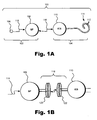
- FIG. 1A illustrates an exemplary cochlear implant system 100.
- the cochlear implant system 100 of FIG. 1A includes a sound processor portion 102 and a cochlear stimulation portion 104.
- the sound processor portion 102 may include a sound processor 106, a microphone 108, and/or additional circuitry as best serves a particular application.
- the cochlear stimulation portion 104 may include an implantable cochlear stimulator 110, a number of electrodes 112 disposed on an electrode lead 114, and/or additional circuitry as best serves a particular application.
- the components within the sound processor portion 102 and the cochlear stimulation portion 104 will be described in more detail below.
- the microphone 108 of FIG. 1A is configured to sense audio signals and convert the sensed signals to corresponding electrical signals.
- the audio signal may include speech.
- the audio signal may additionally or alternatively include music, noise, and/or other sounds.
- the electrical signals are sent from the microphone 108 to the sound processor 106 via a communication link 116.
- the microphone 108 may be connected directly to, or integrated with, the sound processor 106.
- the sound processor 106 processes these converted audio signals in accordance with a selected sound processing strategy to generate appropriate stimulation parameters for controlling the implantable cochlear stimulator 110.
- These stimulation parameters may specify or define the polarity, magnitude, location (i.e., which electrode pair or electrode group receive the electrical stimulation), stimulation rate, timing (i.e., when the electrical stimulation is to be applied to a particular electrode pair), spectral tilt, and/or any other characteristic of the electrical stimulation that is generated by the implantable cochlear stimulator 110.
- the electrode lead 114 shown in FIG. 1A is configured to be inserted within a duct of a cochlea. As shown in FIG. 1A , the electrode lead 114 includes a multiplicity of electrodes 112, e.g., sixteen electrodes, spaced along its length. It will be understood, however, that any number of electrodes 112 may be disposed on the electrode lead 114.
- the electrode lead 114 may be substantially as shown and described in U.S. Patent Nos. 4,819,647 or 6,218,753 .
- electronic circuitry within the implantable cochlear stimulator 110 is configured to generate and apply electrical stimulation to one or more stimulation sites within the cochlea via selected stimulation channels (i.e., pairs or groups of the individual electrodes 112) in accordance with a specified stimulation strategy defined by the sound processor 106.
- the sound processor 106 and the microphone 108 comprise an external portion of the cochlear implant system 100
- the implantable cochlear stimulator 110 and the electrode lead 114 comprise an implantable portion of the system 100 that is implanted within a patient's body.
- one or more portions of the sound processor 106 are included within the implantable portion of the cochlear implant system 100.
- the implantable cochlear stimulator 110 and the sound processor 106 may be communicatively coupled via a suitable data or communication link 118, such as a telemetry communication link, as will be described in more detail below.
- the data communication link 118 may include a bi-directional communication link and/or one or more dedicated uni-directional communication links.
- the external and implantable portions of the cochlear implant system 100 may each include one or more inductive coils configured to transmit and receive power and/or control signals via the communication link 118.
- the control signals may include, for example, the magnitude and polarity of electrical stimulation representing a sensed audio signal.
- the external coil may also transmit power from the external portion to the implantable portion of the cochlear implant system 100. Power transmitted to the implantable portion may be used to operate the implantable portion.
- FIG. 1B illustrates a portion of an exemplary cochlear implant system showing a communication link 118 comprising a telemetry communication link that may be used in accordance with the present systems and methods.
- an external portion of the cochlear implant system 100 may include an external induction coil 120 and an implantable portion of the cochlear implant system 100 may include an implantable induction coil 122.
- the external induction coil 120 may be communicatively coupled to the sound processor 106 and the implantable induction coil 122 may be communicatively coupled to the implantable cochlear stimulator 110.
- the external induction coil 120 and the implantable induction coil 122 may include any suitable type of coil capable of generating and/or receiving an electromagnetic field.
- the external induction coil 120 and the implantable induction coil 122 may each include a metallic wire or tube wound in a coiled or otherwise looped configuration.
- An alternating current may be directed from the sound processor 106 through the external induction coil 120, thereby generating a magnetic field surrounding the external induction coil 120.
- the external induction coil 120 may be positioned near the implantable induction coil 122 such that the implantable induction coil 122 is positioned at least partially within the magnetic field generated by the external induction coil 120.
- the magnetic field generated by the external induction coil 120 may cause an electric current to be generated in the internal induction coil 120.
- the electric current generated in the internal induction coil 120 may be directed from the internal induction coil 120 to the implantable cochlear stimulator 110. Accordingly, an electric current generated by the sound processor 106 may be transferred to the implantable cochlear stimulator 110 through the communication link 118 comprising the external induction coil 120 and the implantable induction coil 122.
- the communication link 118 may function as a telemetry link between the sound processor 106 and the implantable cochlear stimulator 110.
- the external induction coil 120 may transmit one or more telemetry signals to the implantable induction coil 122 by generating a telemetry magnetic field as electric current is passed through the external induction coil 120.
- the telemetry magnetic field generated by the external induction coil 120 may produce an electric current in the implantable induction coil 122, as described above.
- the current generated in the implantable induction coil 122 by the telemetry magnetic field generated by the external induction coil 120 may be used to transfer signals representative of data and/or other information to the implantable cochlear stimulator 110 and/or may be used to transfer power to the implantable cochlear stimulator 110.
- the communication link 118 may be used to transmit telemetry signals from the implantable cochlear stimulator 110 to the sound processor 106.
- data acquired by the electrodes 112 and/or status indicators generated by the cochlear stimulator 112 may be transmitted to sound processor 106 via the communication link 118.
- implantable induction coil 122 may transmit telemetry signals to the external induction coil 120 by generating a telemetry magnetic field.
- the implantable cochlear stimulator 110 may cause a current to flow through the implantable induction coil 122 to generate the telemetry magnetic field.
- the external induction coil 120 may be positioned at least partially within the telemetry magnetic field generated by the implantable induction coil 122.
- the magnetic field may cause an electric current to be generated in the external induction coil 120.
- the current generated in the external induction coil 120 may be used to transfer data and/or other signals to the sound processor 106.
- the communication link 118 may include more than one external induction coil 120 and/or more than one implantable induction coil 122.
- a first external induction coil and a first implantable induction coil may be used to transfer data and/or power from the sound processor 106 to the implantable cochlear stimulator 110.
- a second external induction coil and a second implantable induction coil may be used to transfer data from the implantable cochlear stimulator 110 to the sound processor 106.
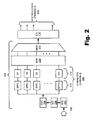
- FIG. 2 is a functional block diagram of an exemplary sound processor 106 and implantable cochlear stimulator 110.
- the functions shown in FIG. 2 are merely representative of the many different functions that may be performed by the sound processor 106 and/or the implantable cochlear stimulator 110.
- the microphone 108 senses an audio signal, such as speech or music, and converts the audio signal into one or more electrical signals. These signals are then amplified in audio front-end (AFE) circuitry 202. The amplified audio signal is then converted to a digital signal by an analog-to-digital (A/D) converter 204. The resulting digital signal is then subjected to automatic gain control using a suitable automatic gain control (AGC) function 206.
- AFE audio front-end
- A/D analog-to-digital
- AGC automatic gain control
- the digital signal is then processed in one of a number of digital signal processing or analysis channels 208.
- the sound processor 106 may include, but is not limited to, sixteen analysis channels 208.
- Each analysis channel 208 may respond to a different frequency band of the sensed audio signal due to a series of band pass filters 210.
- each of the m analysis channels 208 may also include an energy detection stage (D1-Dm) 212.
- Each energy detection stage 212 may include any combination of circuitry configured to detect the amount of energy contained within each of the m analysis channels 208.
- each energy detection stage 212 may include a rectification circuit followed by an integrator circuit.
- the signals within each of the m analysis channels 208 are forwarded to a mapping stage 214.
- the mapping stage 214 is configured to map the signals in each of the m analysis channels 208 to one or more of M stimulation channels 218.
- the information contained in the m analysis channels 208 is used to define the electrical stimulation pulses that are applied to the patient by the implantable cochlear stimulator 110 via the M stimulation channels 218.
- pairs or groups of individual electrodes 112 may make up the M stimulation channels 218.
- the mapped signals are serialized by a multiplexer 216 and transmitted to the implantable cochlear stimulator 110.
- the implantable cochlear stimulator 110 may then apply electrical stimulation via one or more of the M stimulation channels 218 to one or more stimulation sites within the duct of the patient's cochlea.
- stimulation site will be used to refer to a target area or location to which the electrical stimulation is applied.
- a stimulation site may refer to any location within a region of auditory nerve tissue (e.g., auditory nerve tissue 306 shown in FIG. 3 ).
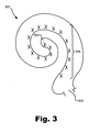
- FIG. 3 illustrates a schematic structure of the human cochlea 300.
- the cochlea 300 is in the shape of a spiral beginning at a base 302 and ending at an apex 304.
- auditory nerve tissue 306 which is denoted by Xs in FIG. 3 .
- the auditory nerve tissue 306 is organized within the cochlea 300 in a tonotopic manner.
- Low frequencies are encoded at the apex 304 of the cochlea 300 while high frequencies are encoded at the base 302.
- each location along the length of the cochlea 300 corresponds to a different perceived frequency.
- a cochlear prosthesis may therefore be implanted within a patient with sensorineural hearing loss and configured to apply electrical stimulation to different locations within the cochlea 300 to provide the sensation of hearing.
- electrode lead 114 may be disposed within the cochlea 300 such that electrodes 112 contact auditory nerve tissue 306 within the cochlea 300. Electrical stimulation may be applied by the electrodes 112 to the auditory nerve tissue 306.
- FIG. 4 illustrates an exemplary configuration of cochlear implant system 100 that may be used to apply electrical stimulation one or more stimulation sites within the cochlea 300.
- the external portion of the cochlear implant system 100 may include an external headpiece 400 configured to be worn on an exterior of a head 402 of the patient.
- the external headpiece 400 may include various components of the sound processor portion 102, including the external induction coil 122 (not shown), as will be described in greater detail below.
- the external headpiece 400 may additionally include electronic circuitry, such as circuitry comprising at least a portion of the sound processor 106.
- the external headpiece 400 may be electrically connected, either directly or indirectly, to a microphone 108 (not shown) positioned in or near the patient's ear via a communication line 404.
- the headpiece 400 may additionally include a retention magnet to position and maintain the headpiece 400 in a proper orientation on the head 402, as will be described in greater detail below.
- an implantable cochlear stimulator 110 may be disposed underneath the skin 406 of the patient.
- a lead 114 with a plurality of electrodes 112 disposed on a distal portion thereof may be coupled to the implantable cochlear stimulator 110 and positioned such that the electrodes 112 are disposed within the cochlea 300.
- the implantable cochlear stimulator 110 may include a receiver 408 configured to facilitate communication with the external headpiece 400.
- the receiver 408 may include the implantable induction coil 122 (not shown) described above.
- the external induction coil 120 in the external headpiece 400 and the implantable induction coil 122 in the receiver 408 may form communication link 118. As described above, data and/or power may be transmitted between the sound processor portion 102 and the cochlear stimulation portion 104 via the communication link 118.
- the external induction coil 120 in the external headpiece 400 may transmit a telemetry signal across the skin 406 to the implantable induction coil 122 in the receiver 408.
- the implantable induction coil 122 in the receiver 408 may transmit a telemetry signal across the skin 406 to the external induction coil 120 in the external headpiece 400.
- FIGS. 5A-5C illustrate an exemplary external headpiece 400 that may be used in accordance with present systems.
- the components shown in FIGS. 5A-5C are merely illustrative of the many different components that may be included within headpiece 400. Additional or alternative components may be included within headpiece 400 as may serve a particular application.
- FIG. 5A is an exploded perspective view of the exemplary external headpiece 400 showing various components of the external headpiece 400.
- FIG. 5B is a perspective view of the exemplary external headpiece 400 shown without a headpiece cover.
- FIG. 5C is cross-sectional side view of the exemplary external headpiece 400 shown without a headpiece cover.
- the external headpiece 400 may include a headpiece cover 500 in which a headpiece cavity 502 is defined.
- the external headpiece 400 may additionally include a headpiece base 504 that may be attached to the headpiece cover 500.
- Components in the external headpiece 400 may be housed in the headpiece cavity 502 such that they are substantially surrounded by headpiece cover 500 and the headpiece base 504.
- the external headpiece 400 includes a circuit board 506 (e.g., a printed circuit board) having electronic circuitry 508 disposed thereon.
- the electronic circuitry 508 may be disposed on any suitable portions of the circuit board 506.
- a bottom surface 510 of the circuit board 506 may face generally towards the headpiece base 504.
- the electronic circuitry 508 may include the sound processor 106 or at least a portion of the sound processor 106.
- the electronic circuitry 508 is configured to direct the implantable cochlear stimulator 110 to generate and apply electrical stimulation to one or more stimulation sites within the cochlea 300 of a patient by transmitting control parameters (including, but not limited to, stimulation parameters) to the implantable cochlear stimulator 110 via communications link 118.
- the electronic circuitry 508 may additionally or alternatively be configured to transmit power to the implantable cochlear stimulator 110 and may be configured to receive data from the cochlear stimulator 110.
- the external headpiece 400 further includes an induction coil 512 disposed below the bottom surface 510 of the circuit board 506.
- the induction coil 512 may include a metallic wire or tube wound in a coiled configuration.
- the induction coil 512 may include a coiled wire arranged in a generally disc-shaped and/or annular-shaped holder. It will be recognized that the induction coil 512 may have any suitable size and shape as may serve a particular application.
- the induction coil 512 may have a top surface 514 and an interior radial surface 516, as illustrated in FIG. 5A .
- the induction coil 512 may be seated in the headpiece base 504. Accordingly, the induction coil 512 may be in close proximity to the head 402 of the patient when the headpiece base 504 is adjacent to the head 402.
- the external headpiece 400 additionally includes a telemetry flux guide 518 positioned or disposed between the circuit board 506 and the induction coil 512.
- the telemetry flux guide 518 may have a generally annular shape with an inner radial surface 520 defining an aperture extending through a central portion of the telemetry flux guide 518.
- the telemetry flux guide may be adjacent to the bottom surface 510 of the circuit board 506 and the top surface 514 of the induction coil 512.
- the telemetry flux guide 518 may include any material suitable for directing magnetic flux away from the circuit board 506.
- the telemetry flux guide 518 may include a material having a relatively high resistivity that provides a low reluctance path for magnetic flux of the telemetry magnetic field.
- the telemetry flux guide 518 may include a powdered material, such as a powdered metallic material having a relatively small particle size, in order to prevent the generation of eddy current in the telemetry flux guide 518.
- eddy currents might be generated in a solid conductive material (as opposed to a powdered conductive material) in the presence of the telemetry magnetic field since the telemetry magnetic field is a changing magnetic field generated by an alternating current passing through the induction coil 512.
- the powdered material in telemetry flux guide 518 may be held together using any suitable material, such as a polymer material.
- the powdered metallic material may include iron and/or other ferrite materials.
- the telemetry flux guide 518 may be suitable for frequencies of telemetry signals generated and/or received by the induction coil 512, such as, for example, an approximately 49 MHz telemetry signal and/or an approximately 10.7 MHz telemetry signal.
- a telemetry flux guide 518 including a material having a relative permeability (i.e., the ratio of the permeability of the alloy to the permeability of free-space) of approximately 9 may be suitable for a frequency range that includes 49 MHz and 10.7 MHz telemetry signals.
- the telemetry flux guide 518 may have any other suitable relative permeability value as may serve a particular application. Additionally or alternatively, telemetry flux guide 518 may have a relatively high resistivity and a relatively small particle size in order to facilitate redirection of magnetic flux while minimizing the generation of eddy currents in the telemetry flux guide 518.
- the telemetry flux guide 518 is positioned and configured to direct magnetic flux of the magnetic field generated by the induction coil 512 away from the circuit board 506, as will be described in greater detail below.
- a telemetry magnetic field may be generated by the induction coil 512 to transmit a telemetry signal.
- Magnetic flux of the telemetry magnetic field is directed away from the circuit board 506 by the telemetry flux guide 518, thereby protecting the electronic circuitry 508 on the circuit board 506 from the telemetry magnetic field.
- the external headpiece 400 additionally includes a retention magnet 522 disposed between the circuit board 506 and the headpiece base 504.
- the retention magnet 522 may have a top surface 524 generally facing the bottom surface 510 of the circuit board 506.
- the retention magnet 522 may additionally have an outer radial surface 526.
- the retention magnet 522 may be positioned in the external headpiece 400 such that the retention magnet 522 is at least partially surrounded by the induction coil 512 and/or the telemetry flux guide 518.
- the outer radial surface 526 of the retention magnet 522 may generally face the inner radial surface 516 of the induction coil 512 and/or the inner radial surface 520 of the telemetry flux guide 518.
- the retention magnet 522 may be positioned in an aperture defined by the inner radial surface 520 extending through the telemetry flux guide 518.
- the retention magnet 522 is configured to produce a retention magnetic field for securing one or more components of a cochlear implant system 100 to a head 402 of a patient.
- the retention magnet 522 may be disposed adjacent to the headpiece base 504 such that the retention magnet 522 is in close proximity to the head 402 of the patient when the headpiece base 504 is adjacent to the head 402.
- a portion of the cochlear stimulation portion 104 of the cochlear implant system 100, such as the receiver 408 shown in FIG. 4 may similarly include a magnet configured to magnetically couple with the retention magnet 522.
- the retention magnet 522 may be magnetically coupled to the magnet of the cochlear stimulation portion 104, thereby securing and/or orienting the external headpiece 400 on the head 402.
- the external headpiece 400 additionally includes a retention flux guide 528 positioned between the circuit board 506 and the retention magnet 522.
- the retention flux guide 528 may at least partially surround the retention magnet 522.
- a top wall 530 of the retention flux guide 528 may be disposed in between and adjacent to the bottom surface 510 of the circuit board 506 and the top surface 524 of the retention magnet 522.
- a side wall 532 of the retention flux guide 528 may at least partially surround the outer radial surface 526 of the retention magnet 522.
- the side wall 532 of the retention flux guide 528 may be adjacent to the outer radial surface 526 of the retention magnet 522, the inner radial surface 516 of the induction coil 512, and/or the inner radial surface 520 of the telemetry flux guide 518.
- the retention flux guide 528 may include any material suitable for redirecting magnetic flux associated with a magnetic field produced by the retention magnet 522.
- the retention flux guide 528 may include a material having a relatively high permeability.
- the retention flux guide 528 may include a metallic material, such as a mu-metal alloy comprising nickel and iron.
- a relatively high permeability mu-metal alloy may have a relative permeability between approximately 60,000 and 300,000.
- a mu-metal alloy may have a relative permeability of approximately 100,000.
- a high-permeability mu-metal alloy may include any suitable ratio of nickel and iron, such as, for example, a ratio of approximately 80% nickel and 20% iron. It will be recognized that the retention flux guide 528 may alternatively include any suitable material having any suitable relative permeability.
- the retention flux guide 528 is configured to direct magnetic flux of a retention magnetic field surrounding the retention magnet 522 away from the circuit board 506 and away from the telemetry flux guide 518. Accordingly, magnetic flux from the retention magnet 522 is directed away from the circuit board 506, thereby protecting the electronic circuitry 508 on the circuit board 506 from the retention magnetic field.
- the retention flux guide 528 also directs magnetic flux of the retention magnetic field away from the telemetry flux guide 518, thereby preventing saturation of powdered metallic material in the telemetry flux guide 518 with magnetic flux from the retention magnet.
- Magnetic flux from the retention magnet 522 may significantly reduce the relative permeability of the powdered metallic material in the telemetry flux guide 518, reducing the effectiveness of the telemetry flux guide 518 in directing magnetic flux from the induction coil 512 away from the circuit board 506. Accordingly, the retention flux guide 528 directs magnetic flux of the retention magnetic field away from the telemetry flux guide 518, thereby preventing magnetic flux from saturating the telemetry flux guide 518.
- the sound processor portion 102 of the cochlear implant system 100 may be made more compact by consolidating electronic and magnetic field emitting components within the headpiece as illustrated in FIGS. 5A-5C .
- This may increase the ease of use and comfort for a patient using the cochlear implant system 100 in comparison to conventional cochlear implant systems in which electronic circuitry is separated from the headpiece.
- a consolidated assembly such as that illustrated in FIGS. 5A-5C , may eliminate the need for a separate behind-the-ear assembly.
- the assembly illustrated in FIGS. 5A-5C may be referred to as a "one piece system headpiece".
- the cochlear stimulation portion 104 of a cochlear implant system 100 may additionally or alternatively include a retention flux guide and/or a telemetry flux guide for directing magnetic flux away from electronic components in the cochlear stimulation portion 104.
- a receiver 408 in the cochlear stimulation portion 104 may include an induction coil and/or a retention magnet, similar to the external headpiece 400 as described above.
- a retention flux guide and/or a telemetry flux guide may be included in the receiver 408 to redirect magnetic flux away from electronic circuitry that may be located in close proximity to the induction coil and/or the retention magnet.
- the external headpiece 400 may include one or more batteries 534 to power the sound processor portion 102 and/or the cochlear stimulation portion 102 of the cochlear implant system 100.
- Batteries 534 may be disposed within the headpiece cover cavity 502 of the headpiece cover 500 and may be located adjacent circuit board 506. In some embodiments, batteries 534 may be located outside of the external headpiece 400.
- FIG. 6 illustrates magnetic flux surrounding an induction coil 512 and a retention magnet 522 in an exemplary external headpiece 400 in accordance with the present systems.
- magnetic flux 600 may surround the induction coil 512.
- the magnetic flux 600 is represented as a flux path surrounding the induction coil 512.
- magnetic flux 602 may pass through and surround retention magnet 522.
- the magnetic flux 602 is represented as flux paths surrounding and passing through the retention magnet 522. It will be recognized that additional flux paths other than those illustrated in FIG. 6 may be associated with the telemetry magnetic field surrounding the induction coil 512 and the retention magnetic field surrounding the retention magnet 522.
- the telemetry flux guide 518 may provide a low reluctance path for the magnetic flux 600 surrounding the induction coil 512. As illustrated in FIG. 6 , the path of the magnetic flux 600 may be directed through the telemetry flux guide 518 such that a path of the magnetic flux 600 between the induction coil 512 and the circuit board 506 may be shortened. The magnetic flux 600 of the telemetry magnetic flux field surrounding the induction coil 512 may therefore be redirected by the telemetry flux guide 518 such that the magnetic flux 600 is substantially prevented from reaching the circuit board 506, thereby reducing or eliminating magnetic flux passing through the electronic circuitry 508.
- the retention flux guide 528 may provide a high permeability path for the magnetic flux 602 surrounding and passing through the retention magnet 522. As illustrated in FIG. 6 , the path of the magnetic flux 602 may be directed through the retention flux guide 528 such that a path of the magnetic flux 602 passes generally through and/or along the top wall 530 and/or the side wall 532 of the retention flux guide 528. Accordingly, a path of the magnetic flux 602 between the induction coil 512 and the circuit board 506 may be shortened. Similarly, a path of the magnetic flux 602 between the retention magnet 522 and the telemetry flux guide 518 may be shortened.
- the magnetic flux 602 of the retention magnetic flux field surrounding and passing through the retention magnet 522 may therefore be redirected by the retention flux guide 528 such that the magnetic flux 602 is substantially prevented from reaching the circuit board 506 and/or the telemetry flux guide 518, thereby reducing or eliminating magnetic flux from the retention magnet passing through the electronic circuitry 508 and/or the telemetry flux guide 518.
Abstract
Description
- The sense of hearing in human beings involves the use of hair cells in the cochlea that convert or transduce audio signals into auditory nerve impulses. Hearing loss, which may be due to many different causes, is generally of two types: conductive and sensorineural. Conductive hearing loss occurs when the normal mechanical pathways for sound to reach the hair cells in the cochlea are impeded. These sound pathways may be impeded, for example, by damage to the auditory ossicles. Conductive hearing loss may often be helped by the use of conventional hearing aids that amplify sound so that audio signals reach the cochlea and the hair cells. Some types of conductive hearing loss may also be treated by surgical procedures.
- Sensorineural hearing loss, on the other hand, is due to the absence or the destruction of the hair cells in the cochlea which are needed to transduce audio signals into auditory nerve impulses. Thus, many people who suffer from severe to profound sensorineural hearing loss are unable to derive any benefit from conventional hearing aid systems. To overcome sensorineural hearing loss, numerous cochlear implant systems, or cochlear prosthesis, have been developed. Cochlear implant systems bypass the hair cells in the cochlea by presenting electrical stimulation directly to the auditory nerve fibers. Direct stimulation of the auditory nerve fibers leads to the perception of sound in the brain and at least partial restoration of hearing function.
- Cochlear implant systems typically include a cochlear stimulator that is implanted beneath the scalp of a patient. An external control assembly located external to the patient's scalp may be used by the patient to control and adjust various operational parameters of the implanted cochlear stimulator. An inductive link is commonly used to transmit telemetry signals from the external control assembly to the implanted cochlear stimulator. To this end, the external control assembly often includes an inductive coil that produces a telemetry signal by generating an electromagnetic field that is picked up by a receiver on the implanted cochlear stimulator. The inductive coil may be housed in an external headpiece that is positioned on a patient's head to transmit the telemetry signal through the patient's scalp to the implanted receiver. The external control often includes a retention magnet for securing the headpiece to the patient's head so that the induction coil is properly positioned adjacent to the implanted receiver.
- In a conventional cochlear implant system, electronic circuitry included within the external control assembly is not placed in relative close proximity to the induction coil and the retention magnet due to losses and interference caused by magnetic flux associated with the induction coil and the retention magnet. Hence, the electronic circuitry is typically housed within a behind-the-ear unit, for example, while the induction coil and the retention magnet are housed separately within a headpiece. Such a configuration is undesirable for many cochlear implant patients. A CI system according the preamble of claim 1 is known from
US 2008/0002384 A1 .US 2005/0113888 A1 relates to CI system comprising an implantable part including a magnetic shield positioned between a secondary recharge coil and the housing of the implantable part.US 6,389,318 B1 relates to a device for transcutaneous energy transfer comprising a primary coil with a magnetic shield mounted over the windinps of the primary cpild in order to reflect a Magnetic field toward the secondary coil. - The invention relates to a cochlear implant system as defined in claim 1.
- The accompanying drawings illustrate various embodiments of the principles described herein and are a part of the specification. The illustrated embodiments are merely examples and do not limit the scope of the disclosure.
-
FIG. 1A illustrates an exemplary cochlear implant system according to principles described herein. -
FIG. 1B illustrates a portion of an exemplary cochlear implant system according to principles described herein. -
FIG. 2 is a functional block diagram of an exemplary sound processor and implantable cochlear stimulator according to principles described herein. -
FIG. 3 illustrates a schematic structure of the human cochlea highlighting elements according to principles described herein. -
FIG. 4 illustrates an exemplary configuration of a cochlear implant system according to principles described herein. -
FIG. 5A is an exploded perspective view of an exemplary external headpiece according to principles described herein. -
FIG. 5B is a perspective view of a portion of an exemplary external headpiece according to principles described herein. -
FIG. 5C is a cross-sectional side view of a portion of an exemplary external headpiece according to principles described herein. -
FIG. 6 illustrates magnetic flux surrounding an induction coil and a retention magnet in an exemplary external headpiece according to principles described herein. - Throughout the drawings, identical reference numbers designate similar, but not necessarily identical, elements.
- Cochlear implant systems including an external headpiece that houses a circuit board having electronic circuitry configured to generate one or more signals configured to control an operation of an implantable cochlear stimulator are described herein. The external headpiece further includes an induction coil configured to transmit a telemetry signal to the implantable cochlear stimulator by generating a telemetry magnetic field. The external headpiece additionally includes a telemetry flux guide positioned between the induction coil and the circuit board. The telemetry flux guide is configured to direct magnetic flux of the telemetry magnetic field away from the circuit board.
- The external headpiece further includes a retention magnet configured to produce a retention magnetic field for securing the headpiece to a head of the patient. In this case, the external headpiece also includes a retention flux guide positioned between the retention magnet and the circuit board. The retention flux guide is configured to direct magnetic flux of the retention magnetic field away from the circuit board.
- In the following description, for purposes of explanation, numerous specific details are set forth in order to provide a thorough understanding of the present systems and methods. It will be apparent, however, to one skilled in the art that the present systems and methods may be practiced without these specific details. Reference in the specification to "one example" or "an example" means that a particular feature, structure, or characteristic described in connection with the example is included in at least one example. The appearance of the phrase "in one example" in various places in the specification are not necessarily all referring to the same example.
-
FIG. 1A illustrates an exemplarycochlear implant system 100. Thecochlear implant system 100 ofFIG. 1A includes asound processor portion 102 and acochlear stimulation portion 104. Thesound processor portion 102 may include asound processor 106, amicrophone 108, and/or additional circuitry as best serves a particular application. Thecochlear stimulation portion 104 may include animplantable cochlear stimulator 110, a number ofelectrodes 112 disposed on anelectrode lead 114, and/or additional circuitry as best serves a particular application. The components within thesound processor portion 102 and thecochlear stimulation portion 104 will be described in more detail below. - The
microphone 108 ofFIG. 1A is configured to sense audio signals and convert the sensed signals to corresponding electrical signals. In some examples, the audio signal may include speech. The audio signal may additionally or alternatively include music, noise, and/or other sounds. The electrical signals are sent from themicrophone 108 to thesound processor 106 via acommunication link 116. Alternatively, themicrophone 108 may be connected directly to, or integrated with, thesound processor 106. Thesound processor 106 processes these converted audio signals in accordance with a selected sound processing strategy to generate appropriate stimulation parameters for controlling the implantablecochlear stimulator 110. These stimulation parameters may specify or define the polarity, magnitude, location (i.e., which electrode pair or electrode group receive the electrical stimulation), stimulation rate, timing (i.e., when the electrical stimulation is to be applied to a particular electrode pair), spectral tilt, and/or any other characteristic of the electrical stimulation that is generated by the implantablecochlear stimulator 110. - The
electrode lead 114 shown inFIG. 1A is configured to be inserted within a duct of a cochlea. As shown inFIG. 1A , theelectrode lead 114 includes a multiplicity ofelectrodes 112, e.g., sixteen electrodes, spaced along its length. It will be understood, however, that any number ofelectrodes 112 may be disposed on theelectrode lead 114. Theelectrode lead 114 may be substantially as shown and described inU.S. Patent Nos. 4,819,647 or6,218,753 . As will be described in more detail below, electronic circuitry within the implantablecochlear stimulator 110 is configured to generate and apply electrical stimulation to one or more stimulation sites within the cochlea via selected stimulation channels (i.e., pairs or groups of the individual electrodes 112) in accordance with a specified stimulation strategy defined by thesound processor 106. - In some examples, the
sound processor 106 and themicrophone 108 comprise an external portion of thecochlear implant system 100, and the implantablecochlear stimulator 110 and theelectrode lead 114 comprise an implantable portion of thesystem 100 that is implanted within a patient's body. In alternative embodiments, one or more portions of thesound processor 106 are included within the implantable portion of thecochlear implant system 100. - The implantable
cochlear stimulator 110 and thesound processor 106 may be communicatively coupled via a suitable data orcommunication link 118, such as a telemetry communication link, as will be described in more detail below. It will be understood that thedata communication link 118 may include a bi-directional communication link and/or one or more dedicated uni-directional communication links. In some examples, the external and implantable portions of thecochlear implant system 100 may each include one or more inductive coils configured to transmit and receive power and/or control signals via thecommunication link 118. The control signals may include, for example, the magnitude and polarity of electrical stimulation representing a sensed audio signal. The external coil may also transmit power from the external portion to the implantable portion of thecochlear implant system 100. Power transmitted to the implantable portion may be used to operate the implantable portion. -
FIG. 1B illustrates a portion of an exemplary cochlear implant system showing acommunication link 118 comprising a telemetry communication link that may be used in accordance with the present systems and methods. As illustrated inFIG. 1B , an external portion of thecochlear implant system 100 may include anexternal induction coil 120 and an implantable portion of thecochlear implant system 100 may include animplantable induction coil 122. Theexternal induction coil 120 may be communicatively coupled to thesound processor 106 and theimplantable induction coil 122 may be communicatively coupled to the implantablecochlear stimulator 110. - The
external induction coil 120 and theimplantable induction coil 122 may include any suitable type of coil capable of generating and/or receiving an electromagnetic field. For example, theexternal induction coil 120 and theimplantable induction coil 122 may each include a metallic wire or tube wound in a coiled or otherwise looped configuration. An alternating current may be directed from thesound processor 106 through theexternal induction coil 120, thereby generating a magnetic field surrounding theexternal induction coil 120. Theexternal induction coil 120 may be positioned near theimplantable induction coil 122 such that theimplantable induction coil 122 is positioned at least partially within the magnetic field generated by theexternal induction coil 120. The magnetic field generated by theexternal induction coil 120 may cause an electric current to be generated in theinternal induction coil 120. The electric current generated in theinternal induction coil 120 may be directed from theinternal induction coil 120 to the implantablecochlear stimulator 110. Accordingly, an electric current generated by thesound processor 106 may be transferred to the implantablecochlear stimulator 110 through thecommunication link 118 comprising theexternal induction coil 120 and theimplantable induction coil 122. - The
communication link 118 may function as a telemetry link between thesound processor 106 and the implantablecochlear stimulator 110. For example, theexternal induction coil 120 may transmit one or more telemetry signals to theimplantable induction coil 122 by generating a telemetry magnetic field as electric current is passed through theexternal induction coil 120. The telemetry magnetic field generated by theexternal induction coil 120 may produce an electric current in theimplantable induction coil 122, as described above. The current generated in theimplantable induction coil 122 by the telemetry magnetic field generated by theexternal induction coil 120 may be used to transfer signals representative of data and/or other information to the implantablecochlear stimulator 110 and/or may be used to transfer power to the implantablecochlear stimulator 110. - In some examples, the
communication link 118 may be used to transmit telemetry signals from the implantablecochlear stimulator 110 to thesound processor 106. For example, data acquired by theelectrodes 112 and/or status indicators generated by thecochlear stimulator 112 may be transmitted to soundprocessor 106 via thecommunication link 118. To this end,implantable induction coil 122 may transmit telemetry signals to theexternal induction coil 120 by generating a telemetry magnetic field. The implantablecochlear stimulator 110 may cause a current to flow through theimplantable induction coil 122 to generate the telemetry magnetic field. Theexternal induction coil 120 may be positioned at least partially within the telemetry magnetic field generated by theimplantable induction coil 122. The magnetic field may cause an electric current to be generated in theexternal induction coil 120. The current generated in theexternal induction coil 120 may be used to transfer data and/or other signals to thesound processor 106. - The
communication link 118 may include more than oneexternal induction coil 120 and/or more than oneimplantable induction coil 122. For example, a first external induction coil and a first implantable induction coil may be used to transfer data and/or power from thesound processor 106 to the implantablecochlear stimulator 110. A second external induction coil and a second implantable induction coil may be used to transfer data from the implantablecochlear stimulator 110 to thesound processor 106. -
FIG. 2 is a functional block diagram of anexemplary sound processor 106 and implantablecochlear stimulator 110. The functions shown inFIG. 2 are merely representative of the many different functions that may be performed by thesound processor 106 and/or the implantablecochlear stimulator 110. - As shown in
FIG. 2 , themicrophone 108 senses an audio signal, such as speech or music, and converts the audio signal into one or more electrical signals. These signals are then amplified in audio front-end (AFE)circuitry 202. The amplified audio signal is then converted to a digital signal by an analog-to-digital (A/D)converter 204. The resulting digital signal is then subjected to automatic gain control using a suitable automatic gain control (AGC)function 206. - After appropriate automatic gain control, the digital signal is then processed in one of a number of digital signal processing or
analysis channels 208. For example, thesound processor 106 may include, but is not limited to, sixteenanalysis channels 208. Eachanalysis channel 208 may respond to a different frequency band of the sensed audio signal due to a series of band pass filters 210. - As shown in
FIG. 2 , each of the manalysis channels 208 may also include an energy detection stage (D1-Dm) 212. Eachenergy detection stage 212 may include any combination of circuitry configured to detect the amount of energy contained within each of the manalysis channels 208. For example, eachenergy detection stage 212 may include a rectification circuit followed by an integrator circuit. - After energy detection, the signals within each of the m
analysis channels 208 are forwarded to amapping stage 214. Themapping stage 214 is configured to map the signals in each of the manalysis channels 208 to one or more of M stimulation channels 218. In other words, the information contained in them analysis channels 208 is used to define the electrical stimulation pulses that are applied to the patient by the implantablecochlear stimulator 110 via the M stimulation channels 218. As mentioned previously, pairs or groups ofindividual electrodes 112 may make up the M stimulation channels 218. - In some examples, the mapped signals are serialized by a
multiplexer 216 and transmitted to the implantablecochlear stimulator 110. The implantablecochlear stimulator 110 may then apply electrical stimulation via one or more of the M stimulation channels 218 to one or more stimulation sites within the duct of the patient's cochlea. As used herein, the term "stimulation site" will be used to refer to a target area or location to which the electrical stimulation is applied. For example, a stimulation site may refer to any location within a region of auditory nerve tissue (e.g.,auditory nerve tissue 306 shown inFIG. 3 ). -
FIG. 3 illustrates a schematic structure of thehuman cochlea 300. As shown inFIG. 3 , thecochlea 300 is in the shape of a spiral beginning at abase 302 and ending at an apex 304. Within thecochlea 300 residesauditory nerve tissue 306, which is denoted by Xs inFIG. 3 . Theauditory nerve tissue 306 is organized within thecochlea 300 in a tonotopic manner. Low frequencies are encoded at the apex 304 of thecochlea 300 while high frequencies are encoded at thebase 302. Hence, each location along the length of thecochlea 300 corresponds to a different perceived frequency. A cochlear prosthesis may therefore be implanted within a patient with sensorineural hearing loss and configured to apply electrical stimulation to different locations within thecochlea 300 to provide the sensation of hearing. For example,electrode lead 114 may be disposed within thecochlea 300 such thatelectrodes 112 contactauditory nerve tissue 306 within thecochlea 300. Electrical stimulation may be applied by theelectrodes 112 to theauditory nerve tissue 306. -
FIG. 4 illustrates an exemplary configuration ofcochlear implant system 100 that may be used to apply electrical stimulation one or more stimulation sites within thecochlea 300. As shown inFIG. 4 , the external portion of thecochlear implant system 100 may include anexternal headpiece 400 configured to be worn on an exterior of ahead 402 of the patient. Theexternal headpiece 400 may include various components of thesound processor portion 102, including the external induction coil 122 (not shown), as will be described in greater detail below. Theexternal headpiece 400 may additionally include electronic circuitry, such as circuitry comprising at least a portion of thesound processor 106. Theexternal headpiece 400 may be electrically connected, either directly or indirectly, to a microphone 108 (not shown) positioned in or near the patient's ear via acommunication line 404. Theheadpiece 400 may additionally include a retention magnet to position and maintain theheadpiece 400 in a proper orientation on thehead 402, as will be described in greater detail below. - As shown in
FIG. 4 , an implantablecochlear stimulator 110 may be disposed underneath theskin 406 of the patient. A lead 114 with a plurality ofelectrodes 112 disposed on a distal portion thereof may be coupled to the implantablecochlear stimulator 110 and positioned such that theelectrodes 112 are disposed within thecochlea 300. - In some examples, the implantable
cochlear stimulator 110 may include areceiver 408 configured to facilitate communication with theexternal headpiece 400. Thereceiver 408 may include the implantable induction coil 122 (not shown) described above. - The
external induction coil 120 in theexternal headpiece 400 and theimplantable induction coil 122 in thereceiver 408 may formcommunication link 118. As described above, data and/or power may be transmitted between thesound processor portion 102 and thecochlear stimulation portion 104 via thecommunication link 118. For example, theexternal induction coil 120 in theexternal headpiece 400 may transmit a telemetry signal across theskin 406 to theimplantable induction coil 122 in thereceiver 408. Additionally or alternatively, theimplantable induction coil 122 in thereceiver 408 may transmit a telemetry signal across theskin 406 to theexternal induction coil 120 in theexternal headpiece 400. -
FIGS. 5A-5C illustrate an exemplaryexternal headpiece 400 that may be used in accordance with present systems. The components shown inFIGS. 5A-5C are merely illustrative of the many different components that may be included withinheadpiece 400. Additional or alternative components may be included withinheadpiece 400 as may serve a particular application. -
FIG. 5A is an exploded perspective view of the exemplaryexternal headpiece 400 showing various components of theexternal headpiece 400.FIG. 5B is a perspective view of the exemplaryexternal headpiece 400 shown without a headpiece cover.FIG. 5C is cross-sectional side view of the exemplaryexternal headpiece 400 shown without a headpiece cover. As shown inFIGS. 5A-5C , theexternal headpiece 400 may include aheadpiece cover 500 in which aheadpiece cavity 502 is defined. Theexternal headpiece 400 may additionally include aheadpiece base 504 that may be attached to theheadpiece cover 500. Components in theexternal headpiece 400 may be housed in theheadpiece cavity 502 such that they are substantially surrounded byheadpiece cover 500 and theheadpiece base 504. - The
external headpiece 400 includes a circuit board 506 (e.g., a printed circuit board) havingelectronic circuitry 508 disposed thereon. Theelectronic circuitry 508 may be disposed on any suitable portions of thecircuit board 506. Abottom surface 510 of thecircuit board 506 may face generally towards theheadpiece base 504. Theelectronic circuitry 508 may include thesound processor 106 or at least a portion of thesound processor 106. Theelectronic circuitry 508 is configured to direct the implantablecochlear stimulator 110 to generate and apply electrical stimulation to one or more stimulation sites within thecochlea 300 of a patient by transmitting control parameters (including, but not limited to, stimulation parameters) to the implantablecochlear stimulator 110 via communications link 118. Theelectronic circuitry 508 may additionally or alternatively be configured to transmit power to the implantablecochlear stimulator 110 and may be configured to receive data from thecochlear stimulator 110. - The
external headpiece 400 further includes aninduction coil 512 disposed below thebottom surface 510 of thecircuit board 506. Theinduction coil 512 may include a metallic wire or tube wound in a coiled configuration. In some examples, theinduction coil 512 may include a coiled wire arranged in a generally disc-shaped and/or annular-shaped holder. It will be recognized that theinduction coil 512 may have any suitable size and shape as may serve a particular application. - The
induction coil 512 may have atop surface 514 and an interiorradial surface 516, as illustrated inFIG. 5A . Theinduction coil 512 may be seated in theheadpiece base 504. Accordingly, theinduction coil 512 may be in close proximity to thehead 402 of the patient when theheadpiece base 504 is adjacent to thehead 402. - The
external headpiece 400 additionally includes atelemetry flux guide 518 positioned or disposed between thecircuit board 506 and theinduction coil 512. Thetelemetry flux guide 518 may have a generally annular shape with an innerradial surface 520 defining an aperture extending through a central portion of thetelemetry flux guide 518. The telemetry flux guide may be adjacent to thebottom surface 510 of thecircuit board 506 and thetop surface 514 of theinduction coil 512. - The
telemetry flux guide 518 may include any material suitable for directing magnetic flux away from thecircuit board 506. For example, thetelemetry flux guide 518 may include a material having a relatively high resistivity that provides a low reluctance path for magnetic flux of the telemetry magnetic field. Additionally, thetelemetry flux guide 518 may include a powdered material, such as a powdered metallic material having a relatively small particle size, in order to prevent the generation of eddy current in thetelemetry flux guide 518. For example, eddy currents might be generated in a solid conductive material (as opposed to a powdered conductive material) in the presence of the telemetry magnetic field since the telemetry magnetic field is a changing magnetic field generated by an alternating current passing through theinduction coil 512. - The powdered material in
telemetry flux guide 518 may be held together using any suitable material, such as a polymer material. In some examples, the powdered metallic material may include iron and/or other ferrite materials. Additionally, thetelemetry flux guide 518 may be suitable for frequencies of telemetry signals generated and/or received by theinduction coil 512, such as, for example, an approximately 49 MHz telemetry signal and/or an approximately 10.7 MHz telemetry signal. Atelemetry flux guide 518 including a material having a relative permeability (i.e., the ratio of the permeability of the alloy to the permeability of free-space) of approximately 9 may be suitable for a frequency range that includes 49 MHz and 10.7 MHz telemetry signals. However, it will be recognized that thetelemetry flux guide 518 may have any other suitable relative permeability value as may serve a particular application. Additionally or alternatively,telemetry flux guide 518 may have a relatively high resistivity and a relatively small particle size in order to facilitate redirection of magnetic flux while minimizing the generation of eddy currents in thetelemetry flux guide 518. - The
telemetry flux guide 518 is positioned and configured to direct magnetic flux of the magnetic field generated by theinduction coil 512 away from thecircuit board 506, as will be described in greater detail below. For example, a telemetry magnetic field may be generated by theinduction coil 512 to transmit a telemetry signal. Magnetic flux of the telemetry magnetic field is directed away from thecircuit board 506 by thetelemetry flux guide 518, thereby protecting theelectronic circuitry 508 on thecircuit board 506 from the telemetry magnetic field. By directing the magnetic flux in the telemetry magnetic field away from thecircuit board 506, energy losses from theinduction coil 512 to theelectronic circuitry 508 via the telemetry magnetic field may be minimized, thereby extending the life of batteries used to provide power to one or more components of thecochlear implant system 100. - The
external headpiece 400 additionally includes aretention magnet 522 disposed between thecircuit board 506 and theheadpiece base 504. Theretention magnet 522 may have atop surface 524 generally facing thebottom surface 510 of thecircuit board 506. Theretention magnet 522 may additionally have an outerradial surface 526. In some embodiments, theretention magnet 522 may be positioned in theexternal headpiece 400 such that theretention magnet 522 is at least partially surrounded by theinduction coil 512 and/or thetelemetry flux guide 518. Accordingly, the outerradial surface 526 of theretention magnet 522 may generally face the innerradial surface 516 of theinduction coil 512 and/or the innerradial surface 520 of thetelemetry flux guide 518. For example, theretention magnet 522 may be positioned in an aperture defined by the innerradial surface 520 extending through thetelemetry flux guide 518. - The
retention magnet 522 is configured to produce a retention magnetic field for securing one or more components of acochlear implant system 100 to ahead 402 of a patient. For example, theretention magnet 522 may be disposed adjacent to theheadpiece base 504 such that theretention magnet 522 is in close proximity to thehead 402 of the patient when theheadpiece base 504 is adjacent to thehead 402. A portion of thecochlear stimulation portion 104 of thecochlear implant system 100, such as thereceiver 408 shown inFIG. 4 , may similarly include a magnet configured to magnetically couple with theretention magnet 522. Accordingly, when theheadpiece base 504 is positioned adjacent to thehead 402 of the patient near thereceiver 408, theretention magnet 522 may be magnetically coupled to the magnet of thecochlear stimulation portion 104, thereby securing and/or orienting theexternal headpiece 400 on thehead 402. - The
external headpiece 400 additionally includes aretention flux guide 528 positioned between thecircuit board 506 and theretention magnet 522. Theretention flux guide 528 may at least partially surround theretention magnet 522. As illustrated inFIGS. 5A and5C , atop wall 530 of theretention flux guide 528 may be disposed in between and adjacent to thebottom surface 510 of thecircuit board 506 and thetop surface 524 of theretention magnet 522. Additionally, aside wall 532 of theretention flux guide 528 may at least partially surround the outerradial surface 526 of theretention magnet 522. Theside wall 532 of theretention flux guide 528 may be adjacent to the outerradial surface 526 of theretention magnet 522, the innerradial surface 516 of theinduction coil 512, and/or the innerradial surface 520 of thetelemetry flux guide 518. - The
retention flux guide 528 may include any material suitable for redirecting magnetic flux associated with a magnetic field produced by theretention magnet 522. For example, theretention flux guide 528 may include a material having a relatively high permeability. In some examples, theretention flux guide 528 may include a metallic material, such as a mu-metal alloy comprising nickel and iron. A relatively high permeability mu-metal alloy may have a relative permeability between approximately 60,000 and 300,000. For example, a mu-metal alloy may have a relative permeability of approximately 100,000. A high-permeability mu-metal alloy may include any suitable ratio of nickel and iron, such as, for example, a ratio of approximately 80% nickel and 20% iron. It will be recognized that theretention flux guide 528 may alternatively include any suitable material having any suitable relative permeability. - The
retention flux guide 528 is configured to direct magnetic flux of a retention magnetic field surrounding theretention magnet 522 away from thecircuit board 506 and away from thetelemetry flux guide 518. Accordingly, magnetic flux from theretention magnet 522 is directed away from thecircuit board 506, thereby protecting theelectronic circuitry 508 on thecircuit board 506 from the retention magnetic field. - As mentioned, the
retention flux guide 528 also directs magnetic flux of the retention magnetic field away from thetelemetry flux guide 518, thereby preventing saturation of powdered metallic material in thetelemetry flux guide 518 with magnetic flux from the retention magnet. Magnetic flux from theretention magnet 522 may significantly reduce the relative permeability of the powdered metallic material in thetelemetry flux guide 518, reducing the effectiveness of thetelemetry flux guide 518 in directing magnetic flux from theinduction coil 512 away from thecircuit board 506. Accordingly, theretention flux guide 528 directs magnetic flux of the retention magnetic field away from thetelemetry flux guide 518, thereby preventing magnetic flux from saturating thetelemetry flux guide 518. - By directing magnetic flux away from the
electronic circuitry 508 in thecircuit board 506, thetelemetry flux guide 518 and theretention flux guide 528 enable theinduction coil 512 and theretention magnet 522 to be located within theexternal headpiece 400 in relatively close proximity to thecircuit board 506. Accordingly, thesound processor portion 102 of thecochlear implant system 100 may be made more compact by consolidating electronic and magnetic field emitting components within the headpiece as illustrated inFIGS. 5A-5C . This may increase the ease of use and comfort for a patient using thecochlear implant system 100 in comparison to conventional cochlear implant systems in which electronic circuitry is separated from the headpiece. For example, a consolidated assembly, such as that illustrated inFIGS. 5A-5C , may eliminate the need for a separate behind-the-ear assembly. Hence, the assembly illustrated inFIGS. 5A-5C may be referred to as a "one piece system headpiece". - In some embodiments, the
cochlear stimulation portion 104 of acochlear implant system 100 may additionally or alternatively include a retention flux guide and/or a telemetry flux guide for directing magnetic flux away from electronic components in thecochlear stimulation portion 104. For example, areceiver 408 in thecochlear stimulation portion 104 may include an induction coil and/or a retention magnet, similar to theexternal headpiece 400 as described above. A retention flux guide and/or a telemetry flux guide may be included in thereceiver 408 to redirect magnetic flux away from electronic circuitry that may be located in close proximity to the induction coil and/or the retention magnet. - Additionally, as illustrated in
FIGS. 5B and 5C , theexternal headpiece 400 may include one ormore batteries 534 to power thesound processor portion 102 and/or thecochlear stimulation portion 102 of thecochlear implant system 100.Batteries 534 may be disposed within theheadpiece cover cavity 502 of theheadpiece cover 500 and may be locatedadjacent circuit board 506. In some embodiments,batteries 534 may be located outside of theexternal headpiece 400. -
FIG. 6 illustrates magnetic flux surrounding aninduction coil 512 and aretention magnet 522 in an exemplaryexternal headpiece 400 in accordance with the present systems. As illustrated inFIG. 6 ,magnetic flux 600 may surround theinduction coil 512. Themagnetic flux 600 is represented as a flux path surrounding theinduction coil 512. Additionally,magnetic flux 602 may pass through and surroundretention magnet 522. Themagnetic flux 602 is represented as flux paths surrounding and passing through theretention magnet 522. It will be recognized that additional flux paths other than those illustrated inFIG. 6 may be associated with the telemetry magnetic field surrounding theinduction coil 512 and the retention magnetic field surrounding theretention magnet 522. - The
telemetry flux guide 518 may provide a low reluctance path for themagnetic flux 600 surrounding theinduction coil 512. As illustrated inFIG. 6 , the path of themagnetic flux 600 may be directed through thetelemetry flux guide 518 such that a path of themagnetic flux 600 between theinduction coil 512 and thecircuit board 506 may be shortened. Themagnetic flux 600 of the telemetry magnetic flux field surrounding theinduction coil 512 may therefore be redirected by thetelemetry flux guide 518 such that themagnetic flux 600 is substantially prevented from reaching thecircuit board 506, thereby reducing or eliminating magnetic flux passing through theelectronic circuitry 508. - The
retention flux guide 528 may provide a high permeability path for themagnetic flux 602 surrounding and passing through theretention magnet 522. As illustrated inFIG. 6 , the path of themagnetic flux 602 may be directed through theretention flux guide 528 such that a path of themagnetic flux 602 passes generally through and/or along thetop wall 530 and/or theside wall 532 of theretention flux guide 528. Accordingly, a path of themagnetic flux 602 between theinduction coil 512 and thecircuit board 506 may be shortened. Similarly, a path of themagnetic flux 602 between theretention magnet 522 and thetelemetry flux guide 518 may be shortened. Themagnetic flux 602 of the retention magnetic flux field surrounding and passing through theretention magnet 522 may therefore be redirected by theretention flux guide 528 such that themagnetic flux 602 is substantially prevented from reaching thecircuit board 506 and/or thetelemetry flux guide 518, thereby reducing or eliminating magnetic flux from the retention magnet passing through theelectronic circuitry 508 and/or thetelemetry flux guide 518. - The preceding description has been presented only to illustrate and describe embodiments of the invention. It is not intended to be exhaustive or to limit the invention to any precise form disclosed. Many modifications and variations are possible in light of the above teaching, without departing from the scope of the appended claims.
Claims (8)
- A cochlear implant system comprising:an external headpiece (400) that housesa circuit board comprising electronic circuitry (508) configured to generate one or more signals comprising stimulation parameters configured to direct an implantable cochlear stimulator (110) to apply electrical stimulation to one or more stimulation sites within a patient;an induction coil (512) configured to transmit said one or more signals to said implantable stimulator by generating a telemetry magnetic field; anda retention magnet (522) configured to produce a retention magnetic field for securing the external headpiece to an exterior a head of said patient;characetrized in that the headpiece further houses
a telemetry flux guide (518) positioned between said induction coil and said circuit board, wherein said telemetry flux guide is configured to direct magnetic flux of said telemetry magnetic field away from said circuit board; and
a retention flux guide (528) positioned between said retention magnet and said circuit board, wherein said retention flux guide is configured to direct magnetic flux of said retention magnetic field away from said circuit board and from said telemetry flux guide, wherein at least a portion of said retention flux guide is positioned between said retention magnet and said telemetry flux guide. - The cochlear implant system of claim 1, wherein said retention magnet (522) is positioned in an aperture (520) extending through said telemetry flux guide (518).
- The cochlear implant system of claim 1, wherein said retention flux guide (528) comprises a metal having a comparatively high relative permeability.
- The cochlear implant system of claim 1, wherein said retention flux guide (528) has a relative permeability between approximately 60,000 and approximately 300,000.
- The cochlear implant system of claim 1, wherein said retention magnet (522) is at least partially surrounded by the telemetry flux guide (518).
- The cochlear implant system of claim 1, further comprising an implantable cochlear stimulator (110), wherein the implantable cochlear stimulator (110) comprises:a receiver comprising a second induction coil (122,) configured to receive said telemetry signal; anda lead (114) electrically coupled to said receiver, said electrode lead comprising a plurality of electrodes (112) configured to be in communication with one or more stimulation sites within a cochlea of a patient.
- The cochlear implant system of claim 6, wherein
said retention magnet (522) is configured to be magnetically coupled to a portion of said implantable cochlear stimulator (110). - The cochlear implant device of claim 6, wherein
said implantable cochlear stimulator (110) is configured to be disposed internally within said head of said patient such that said second induction coil (122) is positioned at least partially within said telemetry magnetic field generated by said first induction coil (120, 512).
Applications Claiming Priority (4)
| Application Number | Priority Date | Filing Date | Title |
|---|---|---|---|
| US11367508P | 2008-11-12 | 2008-11-12 | |
| US11370808P | 2008-11-12 | 2008-11-12 | |
| US13956708P | 2008-12-20 | 2008-12-20 | |
| PCT/US2009/064033 WO2010056751A1 (en) | 2008-11-12 | 2009-11-11 | Cochlear implant systems including magnetic flux redirection means |
Publications (3)
| Publication Number | Publication Date |
|---|---|
| EP2355889A1 EP2355889A1 (en) | 2011-08-17 |
| EP2355889A4 EP2355889A4 (en) | 2012-09-12 |
| EP2355889B1 true EP2355889B1 (en) | 2013-12-18 |
Family
ID=42170301
Family Applications (1)
| Application Number | Title | Priority Date | Filing Date |
|---|---|---|---|
| EP09826674.5A Active EP2355889B1 (en) | 2008-11-12 | 2009-11-11 | Cochlear implant systems including magnetic flux redirection means |
Country Status (4)
| Country | Link |
|---|---|
| US (2) | US8897883B2 (en) |
| EP (1) | EP2355889B1 (en) |
| AU (2) | AU2009101376A4 (en) |
| WO (1) | WO2010056751A1 (en) |
Families Citing this family (36)
| Publication number | Priority date | Publication date | Assignee | Title |
|---|---|---|---|---|
| US7599508B1 (en) | 2003-05-08 | 2009-10-06 | Advanced Bionics, Llc | Listening device cap |
| US8811643B2 (en) | 2003-05-08 | 2014-08-19 | Advanced Bionics | Integrated cochlear implant headpiece |
| US8270647B2 (en) | 2003-05-08 | 2012-09-18 | Advanced Bionics, Llc | Modular speech processor headpiece |
| ES2733540T3 (en) | 2010-04-23 | 2019-11-29 | Med El Elektromedizinische Geraete Gmbh | Disk magnet for MRI-proof implants |
| US8884779B2 (en) | 2011-06-24 | 2014-11-11 | Medtronic, Inc. | EMI shield for medical device telemetry antenna |
| US9031274B2 (en) | 2012-09-06 | 2015-05-12 | Sophono, Inc. | Adhesive bone conduction hearing device |
| US9119010B2 (en) | 2011-12-09 | 2015-08-25 | Sophono, Inc. | Implantable sound transmission device for magnetic hearing aid, and corresponding systems, devices and components |
| US9736601B2 (en) | 2012-07-16 | 2017-08-15 | Sophono, Inc. | Adjustable magnetic systems, devices, components and methods for bone conduction hearing aids |
| US9258656B2 (en) | 2011-12-09 | 2016-02-09 | Sophono, Inc. | Sound acquisition and analysis systems, devices and components for magnetic hearing aids |
| US9179228B2 (en) | 2011-12-09 | 2015-11-03 | Sophono, Inc. | Systems devices, components and methods for providing acoustic isolation between microphones and transducers in bone conduction magnetic hearing aids |
| US9210521B2 (en) | 2012-07-16 | 2015-12-08 | Sophono, Inc. | Abutment attachment systems, mechanisms, devices, components and methods for bone conduction hearing aids |
| US9526810B2 (en) | 2011-12-09 | 2016-12-27 | Sophono, Inc. | Systems, devices, components and methods for improved acoustic coupling between a bone conduction hearing device and a patient's head or skull |
| US9022917B2 (en) | 2012-07-16 | 2015-05-05 | Sophono, Inc. | Magnetic spacer systems, devices, components and methods for bone conduction hearing aids |
| US9161140B2 (en) | 2014-01-28 | 2015-10-13 | Cochlear Limited | Medical device for lessening the effects of noise and interference from varying or alternating magnetic fields |
| US10118043B2 (en) | 2014-03-18 | 2018-11-06 | Cochlear Limited | Coil for signal transmission to implantable device |
| EP3790290A1 (en) | 2014-05-27 | 2021-03-10 | Sophono, Inc. | Systems, devices, components and methods for reducing feedback between microphones and transducers in bone conduction magnetic hearing devices |
| US9800982B2 (en) | 2014-06-18 | 2017-10-24 | Cochlear Limited | Electromagnetic transducer with expanded magnetic flux functionality |
| WO2016012863A2 (en) | 2014-07-23 | 2016-01-28 | Cochlear Limited | Shielding device for signal transmission coil |
| USD750602S1 (en) * | 2014-08-15 | 2016-03-01 | Cirocomm Technology Corp. | Antenna |
| US9808623B2 (en) * | 2014-10-07 | 2017-11-07 | Oticon Medical A/S | Hearing system |
| CN107427683B (en) | 2015-01-09 | 2019-06-21 | 艾克索尼克斯调制技术股份有限公司 | For can plant the improvement antenna and application method of nerve stimulator |
| US10130807B2 (en) | 2015-06-12 | 2018-11-20 | Cochlear Limited | Magnet management MRI compatibility |
| US20160381473A1 (en) | 2015-06-26 | 2016-12-29 | Johan Gustafsson | Magnetic retention device |
| WO2016207856A1 (en) | 2015-06-26 | 2016-12-29 | Cochlear Limited | Magnetic retention device |
| US10917730B2 (en) | 2015-09-14 | 2021-02-09 | Cochlear Limited | Retention magnet system for medical device |
| US9872115B2 (en) * | 2015-09-14 | 2018-01-16 | Cochlear Limited | Retention magnet system for medical device |
| KR101688508B1 (en) | 2015-12-04 | 2016-12-21 | 민규식 | Bioartificial implant system |
| US10009698B2 (en) * | 2015-12-16 | 2018-06-26 | Cochlear Limited | Bone conduction device having magnets integrated with housing |
| US11272299B2 (en) * | 2016-07-19 | 2022-03-08 | Cochlear Limited | Battery positioning in an external device |
| US11595768B2 (en) | 2016-12-02 | 2023-02-28 | Cochlear Limited | Retention force increasing components |
| US11467665B2 (en) | 2018-06-14 | 2022-10-11 | Meron Gribetz | Virtual user interface system and methods for use thereof |
| CN112438055B (en) | 2018-07-23 | 2022-05-10 | 领先仿生公司 | Cochlear implant system and method employing near-ear microphone and off-ear acoustic processor |
| CN108969194B (en) * | 2018-08-09 | 2024-04-09 | 浙江诺尔康神经电子科技股份有限公司 | Magnet tool in artificial cochlea |
| US20220331598A1 (en) * | 2019-09-27 | 2022-10-20 | Cochlear Limited | Multipole magnet for medical implant system |
| US20230075205A1 (en) * | 2020-01-14 | 2023-03-09 | Inner Cosmos Inc. | Devices, systems and methods for cortical stimulation |
| DE102020205155A1 (en) * | 2020-04-23 | 2021-10-28 | Sivantos Pte. Ltd. | Battery module and hearing aid |
Family Cites Families (14)
| Publication number | Priority date | Publication date | Assignee | Title |
|---|---|---|---|---|
| US4819647A (en) * | 1984-05-03 | 1989-04-11 | The Regents Of The University Of California | Intracochlear electrode array |
| US5571148A (en) * | 1994-08-10 | 1996-11-05 | Loeb; Gerald E. | Implantable multichannel stimulator |
| US6219580B1 (en) * | 1995-04-26 | 2001-04-17 | Advanced Bionics Corporation | Multichannel cochlear prosthesis with flexible control of stimulus waveforms |
| AU753694B2 (en) * | 1997-08-01 | 2002-10-24 | Advanced Bionics Corporation | Implantable device with improved battery recharging and powering configuration |
| US6389318B1 (en) * | 1998-07-06 | 2002-05-14 | Abiomed, Inc. | Magnetic shield for primary coil of transcutaneous energy transfer device |
| US6324431B1 (en) * | 1998-07-06 | 2001-11-27 | Abiomed, Inc. | Transcutaneous energy transfer device with magnetic field protected components in secondary coil |
| DE19933009A1 (en) * | 1998-07-24 | 2000-02-10 | Matsushita Electric Ind Co Ltd | Electric motor e.g. for automobile air conditioning unit, has rotor core provided with slits for reception of internal permanent magnets with non-magnetic section between each permanent magnet and rotor periphery |
| US6308101B1 (en) * | 1998-07-31 | 2001-10-23 | Advanced Bionics Corporation | Fully implantable cochlear implant system |
| US6272382B1 (en) * | 1998-07-31 | 2001-08-07 | Advanced Bionics Corporation | Fully implantable cochlear implant system |
| US6850803B1 (en) * | 2000-06-16 | 2005-02-01 | Medtronic, Inc. | Implantable medical device with a recharging coil magnetic shield |
| US7162302B2 (en) * | 2002-03-04 | 2007-01-09 | Nanoset Llc | Magnetically shielded assembly |
| US20060190059A1 (en) * | 2004-05-07 | 2006-08-24 | Griffith Glen A | Cochlear Stimulation Device |
| AR061291A1 (en) * | 2006-06-09 | 2008-08-20 | Med El Elektromed Geraete Gmbh | PROCESSOR BUTTON FOR COCLEAR IMPLANTS |
| US8996121B2 (en) * | 2009-07-10 | 2015-03-31 | Cochlear Limited | Varying the effective coil area for an inductive transcutaneous power link |
-
2009
- 2009-11-11 WO PCT/US2009/064033 patent/WO2010056751A1/en active Application Filing
- 2009-11-11 EP EP09826674.5A patent/EP2355889B1/en active Active
- 2009-11-11 US US13/128,755 patent/US8897883B2/en active Active
- 2009-11-11 AU AU2009101376A patent/AU2009101376A4/en not_active Expired
- 2009-11-11 AU AU2009314139A patent/AU2009314139A1/en active Pending
-
2014
- 2014-10-24 US US14/523,672 patent/US9155888B2/en active Active
Also Published As
| Publication number | Publication date |
|---|---|
| EP2355889A4 (en) | 2012-09-12 |
| AU2009101376A4 (en) | 2013-06-27 |
| AU2009314139A1 (en) | 2011-06-30 |
| US9155888B2 (en) | 2015-10-13 |
| EP2355889A1 (en) | 2011-08-17 |
| WO2010056751A1 (en) | 2010-05-20 |
| US20110224789A1 (en) | 2011-09-15 |
| US20150045855A1 (en) | 2015-02-12 |
| US8897883B2 (en) | 2014-11-25 |
Similar Documents
| Publication | Publication Date | Title |
|---|---|---|
| EP2355889B1 (en) | Cochlear implant systems including magnetic flux redirection means | |
| US11583677B2 (en) | Cochlear implant headpiece | |
| AU2009101370A4 (en) | Modular speech processor headpiece | |
| US8655449B2 (en) | Modular cochlear implant systems including implantable sound processors | |
| EP2376186B1 (en) | Integrated cochlear implant headpiece | |
| EP2326107B1 (en) | Cochlear implant | |
| EP2318095B1 (en) | External button processor with a rechargeable battery | |
| US20060190059A1 (en) | Cochlear Stimulation Device | |
| EP2545960A1 (en) | Fully-implantable, microphoneless cochlear implant | |
| CN102740926A (en) | Stimulus timing for a stimulating medical device | |
| US8977369B1 (en) | Sound processing assembly for use in a cochlear implant system | |
| US20110112607A1 (en) | Implant Power Control | |
| US20130289656A1 (en) | Methods and systems of conveying fine structure information to a cochlear implant patient | |
| EP2491728A1 (en) | Remote audio processor module for auditory prosthesis systems | |
| JP2004534567A (en) | Endosteal electrode | |
| EP3036917A1 (en) | Device and method for neural cochlea stimulation | |
| US8437859B1 (en) | Dual microphone EAS system that prevents feedback | |
| US20070213788A1 (en) | Electrical stimulation of the inner ear in patients with unilateral hearing loss |
Legal Events
| Date | Code | Title | Description |
|---|---|---|---|
| PUAI | Public reference made under article 153(3) epc to a published international application that has entered the european phase |
Free format text: ORIGINAL CODE: 0009012 |
|
| 17P | Request for examination filed |
Effective date: 20110603 |
|
| AK | Designated contracting states |
Kind code of ref document: A1 Designated state(s): AT BE BG CH CY CZ DE DK EE ES FI FR GB GR HR HU IE IS IT LI LT LU LV MC MK MT NL NO PL PT RO SE SI SK SM TR |
|
| DAX | Request for extension of the european patent (deleted) | ||
| A4 | Supplementary search report drawn up and despatched |
Effective date: 20120816 |
|
| RIC1 | Information provided on ipc code assigned before grant |
Ipc: H01Q 17/00 20060101ALI20120809BHEP Ipc: H01Q 1/27 20060101ALI20120809BHEP Ipc: A61N 1/37 20060101ALN20120809BHEP Ipc: A61N 1/378 20060101ALI20120809BHEP Ipc: H05K 9/00 20060101ALI20120809BHEP Ipc: A61N 1/372 20060101AFI20120809BHEP Ipc: H04R 25/00 20060101ALN20120809BHEP Ipc: A61N 1/36 20060101ALI20120809BHEP Ipc: H05K 1/02 20060101ALI20120809BHEP Ipc: A61N 1/375 20060101ALN20120809BHEP |
|
| RIC1 | Information provided on ipc code assigned before grant |
Ipc: H01Q 7/00 20060101ALI20130402BHEP Ipc: H05K 1/02 20060101ALI20130402BHEP Ipc: A61N 1/378 20060101ALI20130402BHEP Ipc: H05K 9/00 20060101ALI20130402BHEP Ipc: A61N 1/375 20060101ALN20130402BHEP Ipc: H01Q 1/27 20060101ALI20130402BHEP Ipc: A61N 1/37 20060101ALN20130402BHEP Ipc: A61N 1/372 20060101AFI20130402BHEP Ipc: H01Q 17/00 20060101ALI20130402BHEP Ipc: A61N 1/36 20060101ALI20130402BHEP Ipc: H04R 25/00 20060101ALN20130402BHEP |
|
| REG | Reference to a national code |
Ref country code: DE Ref legal event code: R079 Ref document number: 602009020885 Country of ref document: DE Free format text: PREVIOUS MAIN CLASS: A61N0001020000 Ipc: A61N0001372000 |
|
| RIC1 | Information provided on ipc code assigned before grant |
Ipc: A61N 1/375 20060101ALN20130417BHEP Ipc: H01Q 7/00 20060101ALI20130417BHEP Ipc: H01Q 1/27 20060101ALI20130417BHEP Ipc: A61N 1/378 20060101ALI20130417BHEP Ipc: A61N 1/36 20060101ALI20130417BHEP Ipc: A61N 1/37 20060101ALN20130417BHEP Ipc: H01Q 17/00 20060101ALI20130417BHEP Ipc: H04R 25/00 20060101ALN20130417BHEP Ipc: A61N 1/372 20060101AFI20130417BHEP Ipc: H05K 9/00 20060101ALI20130417BHEP Ipc: H05K 1/02 20060101ALI20130417BHEP |
|
| GRAP | Despatch of communication of intention to grant a patent |
Free format text: ORIGINAL CODE: EPIDOSNIGR1 |
|
| RIC1 | Information provided on ipc code assigned before grant |
Ipc: A61N 1/375 20060101ALN20130516BHEP Ipc: A61N 1/36 20060101ALI20130516BHEP Ipc: A61N 1/37 20060101ALN20130516BHEP Ipc: H05K 9/00 20060101ALI20130516BHEP Ipc: A61N 1/378 20060101ALI20130516BHEP Ipc: A61N 1/372 20060101AFI20130516BHEP Ipc: H01Q 1/27 20060101ALI20130516BHEP Ipc: H05K 1/02 20060101ALI20130516BHEP Ipc: H04R 25/00 20060101ALN20130516BHEP Ipc: H01Q 7/00 20060101ALI20130516BHEP Ipc: H01Q 17/00 20060101ALI20130516BHEP |
|
| INTG | Intention to grant announced |
Effective date: 20130603 |
|
| GRAS | Grant fee paid |
Free format text: ORIGINAL CODE: EPIDOSNIGR3 |
|
| GRAA | (expected) grant |
Free format text: ORIGINAL CODE: 0009210 |
|
| AK | Designated contracting states |
Kind code of ref document: B1 Designated state(s): AT BE BG CH CY CZ DE DK EE ES FI FR GB GR HR HU IE IS IT LI LT LU LV MC MK MT NL NO PL PT RO SE SI SK SM TR |
|
| REG | Reference to a national code |
Ref country code: GB Ref legal event code: FG4D |
|
| REG | Reference to a national code |
Ref country code: CH Ref legal event code: EP |
|
| REG | Reference to a national code |
Ref country code: AT Ref legal event code: REF Ref document number: 645323 Country of ref document: AT Kind code of ref document: T Effective date: 20140115 |
|
| REG | Reference to a national code |
Ref country code: IE Ref legal event code: FG4D |
|
| REG | Reference to a national code |
Ref country code: DE Ref legal event code: R096 Ref document number: 602009020885 Country of ref document: DE Effective date: 20140213 |
|
| REG | Reference to a national code |
Ref country code: NL Ref legal event code: VDEP Effective date: 20131218 |
|
| PG25 | Lapsed in a contracting state [announced via postgrant information from national office to epo] |
Ref country code: HR Free format text: LAPSE BECAUSE OF FAILURE TO SUBMIT A TRANSLATION OF THE DESCRIPTION OR TO PAY THE FEE WITHIN THE PRESCRIBED TIME-LIMIT Effective date: 20131218 Ref country code: FI Free format text: LAPSE BECAUSE OF FAILURE TO SUBMIT A TRANSLATION OF THE DESCRIPTION OR TO PAY THE FEE WITHIN THE PRESCRIBED TIME-LIMIT Effective date: 20131218 Ref country code: SE Free format text: LAPSE BECAUSE OF FAILURE TO SUBMIT A TRANSLATION OF THE DESCRIPTION OR TO PAY THE FEE WITHIN THE PRESCRIBED TIME-LIMIT Effective date: 20131218 Ref country code: LT Free format text: LAPSE BECAUSE OF FAILURE TO SUBMIT A TRANSLATION OF THE DESCRIPTION OR TO PAY THE FEE WITHIN THE PRESCRIBED TIME-LIMIT Effective date: 20131218 Ref country code: NO Free format text: LAPSE BECAUSE OF FAILURE TO SUBMIT A TRANSLATION OF THE DESCRIPTION OR TO PAY THE FEE WITHIN THE PRESCRIBED TIME-LIMIT Effective date: 20140318 |
|
| REG | Reference to a national code |
Ref country code: AT Ref legal event code: MK05 Ref document number: 645323 Country of ref document: AT Kind code of ref document: T Effective date: 20131218 |
|
| REG | Reference to a national code |
Ref country code: LT Ref legal event code: MG4D |
|
| PG25 | Lapsed in a contracting state [announced via postgrant information from national office to epo] |
Ref country code: LV Free format text: LAPSE BECAUSE OF FAILURE TO SUBMIT A TRANSLATION OF THE DESCRIPTION OR TO PAY THE FEE WITHIN THE PRESCRIBED TIME-LIMIT Effective date: 20131218 |
|
| PG25 | Lapsed in a contracting state [announced via postgrant information from national office to epo] |
Ref country code: EE Free format text: LAPSE BECAUSE OF FAILURE TO SUBMIT A TRANSLATION OF THE DESCRIPTION OR TO PAY THE FEE WITHIN THE PRESCRIBED TIME-LIMIT Effective date: 20131218 Ref country code: IS Free format text: LAPSE BECAUSE OF FAILURE TO SUBMIT A TRANSLATION OF THE DESCRIPTION OR TO PAY THE FEE WITHIN THE PRESCRIBED TIME-LIMIT Effective date: 20140418 Ref country code: BE Free format text: LAPSE BECAUSE OF FAILURE TO SUBMIT A TRANSLATION OF THE DESCRIPTION OR TO PAY THE FEE WITHIN THE PRESCRIBED TIME-LIMIT Effective date: 20131218 |
|
| PG25 | Lapsed in a contracting state [announced via postgrant information from national office to epo] |
Ref country code: PT Free format text: LAPSE BECAUSE OF FAILURE TO SUBMIT A TRANSLATION OF THE DESCRIPTION OR TO PAY THE FEE WITHIN THE PRESCRIBED TIME-LIMIT Effective date: 20140418 Ref country code: NL Free format text: LAPSE BECAUSE OF FAILURE TO SUBMIT A TRANSLATION OF THE DESCRIPTION OR TO PAY THE FEE WITHIN THE PRESCRIBED TIME-LIMIT Effective date: 20131218 Ref country code: PL Free format text: LAPSE BECAUSE OF FAILURE TO SUBMIT A TRANSLATION OF THE DESCRIPTION OR TO PAY THE FEE WITHIN THE PRESCRIBED TIME-LIMIT Effective date: 20131218 Ref country code: AT Free format text: LAPSE BECAUSE OF FAILURE TO SUBMIT A TRANSLATION OF THE DESCRIPTION OR TO PAY THE FEE WITHIN THE PRESCRIBED TIME-LIMIT Effective date: 20131218 Ref country code: CY Free format text: LAPSE BECAUSE OF FAILURE TO SUBMIT A TRANSLATION OF THE DESCRIPTION OR TO PAY THE FEE WITHIN THE PRESCRIBED TIME-LIMIT Effective date: 20131218 Ref country code: ES Free format text: LAPSE BECAUSE OF FAILURE TO SUBMIT A TRANSLATION OF THE DESCRIPTION OR TO PAY THE FEE WITHIN THE PRESCRIBED TIME-LIMIT Effective date: 20131218 Ref country code: SK Free format text: LAPSE BECAUSE OF FAILURE TO SUBMIT A TRANSLATION OF THE DESCRIPTION OR TO PAY THE FEE WITHIN THE PRESCRIBED TIME-LIMIT Effective date: 20131218 Ref country code: CZ Free format text: LAPSE BECAUSE OF FAILURE TO SUBMIT A TRANSLATION OF THE DESCRIPTION OR TO PAY THE FEE WITHIN THE PRESCRIBED TIME-LIMIT Effective date: 20131218 Ref country code: RO Free format text: LAPSE BECAUSE OF FAILURE TO SUBMIT A TRANSLATION OF THE DESCRIPTION OR TO PAY THE FEE WITHIN THE PRESCRIBED TIME-LIMIT Effective date: 20131218 |
|
| REG | Reference to a national code |
Ref country code: DE Ref legal event code: R097 Ref document number: 602009020885 Country of ref document: DE |
|
| PLBE | No opposition filed within time limit |
Free format text: ORIGINAL CODE: 0009261 |
|
| STAA | Information on the status of an ep patent application or granted ep patent |
Free format text: STATUS: NO OPPOSITION FILED WITHIN TIME LIMIT |
|
| PG25 | Lapsed in a contracting state [announced via postgrant information from national office to epo] |
Ref country code: DK Free format text: LAPSE BECAUSE OF FAILURE TO SUBMIT A TRANSLATION OF THE DESCRIPTION OR TO PAY THE FEE WITHIN THE PRESCRIBED TIME-LIMIT Effective date: 20131218 |
|
| 26N | No opposition filed |
Effective date: 20140919 |
|
| REG | Reference to a national code |
Ref country code: DE Ref legal event code: R097 Ref document number: 602009020885 Country of ref document: DE Effective date: 20140919 |
|
| PG25 | Lapsed in a contracting state [announced via postgrant information from national office to epo] |
Ref country code: SI Free format text: LAPSE BECAUSE OF FAILURE TO SUBMIT A TRANSLATION OF THE DESCRIPTION OR TO PAY THE FEE WITHIN THE PRESCRIBED TIME-LIMIT Effective date: 20131218 |
|
| PG25 | Lapsed in a contracting state [announced via postgrant information from national office to epo] |
Ref country code: LU Free format text: LAPSE BECAUSE OF FAILURE TO SUBMIT A TRANSLATION OF THE DESCRIPTION OR TO PAY THE FEE WITHIN THE PRESCRIBED TIME-LIMIT Effective date: 20141111 Ref country code: MC Free format text: LAPSE BECAUSE OF FAILURE TO SUBMIT A TRANSLATION OF THE DESCRIPTION OR TO PAY THE FEE WITHIN THE PRESCRIBED TIME-LIMIT Effective date: 20131218 |
|
| REG | Reference to a national code |
Ref country code: CH Ref legal event code: PL |
|
| PG25 | Lapsed in a contracting state [announced via postgrant information from national office to epo] |
Ref country code: CH Free format text: LAPSE BECAUSE OF NON-PAYMENT OF DUE FEES Effective date: 20141130 Ref country code: LI Free format text: LAPSE BECAUSE OF NON-PAYMENT OF DUE FEES Effective date: 20141130 |
|
| REG | Reference to a national code |
Ref country code: IE Ref legal event code: MM4A |
|
| REG | Reference to a national code |
Ref country code: FR Ref legal event code: PLFP Year of fee payment: 7 |
|
| PG25 | Lapsed in a contracting state [announced via postgrant information from national office to epo] |
Ref country code: IE Free format text: LAPSE BECAUSE OF NON-PAYMENT OF DUE FEES Effective date: 20141111 |
|
| PG25 | Lapsed in a contracting state [announced via postgrant information from national office to epo] |
Ref country code: SM Free format text: LAPSE BECAUSE OF FAILURE TO SUBMIT A TRANSLATION OF THE DESCRIPTION OR TO PAY THE FEE WITHIN THE PRESCRIBED TIME-LIMIT Effective date: 20131218 |
|
| PG25 | Lapsed in a contracting state [announced via postgrant information from national office to epo] |
Ref country code: BG Free format text: LAPSE BECAUSE OF FAILURE TO SUBMIT A TRANSLATION OF THE DESCRIPTION OR TO PAY THE FEE WITHIN THE PRESCRIBED TIME-LIMIT Effective date: 20131218 Ref country code: IT Free format text: LAPSE BECAUSE OF FAILURE TO SUBMIT A TRANSLATION OF THE DESCRIPTION OR TO PAY THE FEE WITHIN THE PRESCRIBED TIME-LIMIT Effective date: 20131218 Ref country code: GR Free format text: LAPSE BECAUSE OF FAILURE TO SUBMIT A TRANSLATION OF THE DESCRIPTION OR TO PAY THE FEE WITHIN THE PRESCRIBED TIME-LIMIT Effective date: 20140319 |
|
| PG25 | Lapsed in a contracting state [announced via postgrant information from national office to epo] |
Ref country code: TR Free format text: LAPSE BECAUSE OF FAILURE TO SUBMIT A TRANSLATION OF THE DESCRIPTION OR TO PAY THE FEE WITHIN THE PRESCRIBED TIME-LIMIT Effective date: 20131218 Ref country code: HU Free format text: LAPSE BECAUSE OF FAILURE TO SUBMIT A TRANSLATION OF THE DESCRIPTION OR TO PAY THE FEE WITHIN THE PRESCRIBED TIME-LIMIT; INVALID AB INITIO Effective date: 20091111 Ref country code: MT Free format text: LAPSE BECAUSE OF FAILURE TO SUBMIT A TRANSLATION OF THE DESCRIPTION OR TO PAY THE FEE WITHIN THE PRESCRIBED TIME-LIMIT Effective date: 20131218 |
|
| REG | Reference to a national code |
Ref country code: FR Ref legal event code: PLFP Year of fee payment: 8 |
|
| REG | Reference to a national code |
Ref country code: FR Ref legal event code: PLFP Year of fee payment: 9 |
|
| PG25 | Lapsed in a contracting state [announced via postgrant information from national office to epo] |
Ref country code: MK Free format text: LAPSE BECAUSE OF FAILURE TO SUBMIT A TRANSLATION OF THE DESCRIPTION OR TO PAY THE FEE WITHIN THE PRESCRIBED TIME-LIMIT Effective date: 20131218 |
|
| PGFP | Annual fee paid to national office [announced via postgrant information from national office to epo] |
Ref country code: GB Payment date: 20231127 Year of fee payment: 15 |
|
| PGFP | Annual fee paid to national office [announced via postgrant information from national office to epo] |
Ref country code: FR Payment date: 20231127 Year of fee payment: 15 Ref country code: DE Payment date: 20231129 Year of fee payment: 15 |