EP2355684B1 - Vacuum cleaner air outlet - Google Patents
Vacuum cleaner air outlet Download PDFInfo
- Publication number
- EP2355684B1 EP2355684B1 EP09736836A EP09736836A EP2355684B1 EP 2355684 B1 EP2355684 B1 EP 2355684B1 EP 09736836 A EP09736836 A EP 09736836A EP 09736836 A EP09736836 A EP 09736836A EP 2355684 B1 EP2355684 B1 EP 2355684B1
- Authority
- EP
- European Patent Office
- Prior art keywords
- vacuum cleaner
- separation chamber
- parts
- fan unit
- air
- Prior art date
- Legal status (The legal status is an assumption and is not a legal conclusion. Google has not performed a legal analysis and makes no representation as to the accuracy of the status listed.)
- Active
Links
Images


Classifications
-
- A—HUMAN NECESSITIES
- A47—FURNITURE; DOMESTIC ARTICLES OR APPLIANCES; COFFEE MILLS; SPICE MILLS; SUCTION CLEANERS IN GENERAL
- A47L—DOMESTIC WASHING OR CLEANING; SUCTION CLEANERS IN GENERAL
- A47L5/00—Structural features of suction cleaners
- A47L5/12—Structural features of suction cleaners with power-driven air-pumps or air-compressors, e.g. driven by motor vehicle engine vacuum
- A47L5/22—Structural features of suction cleaners with power-driven air-pumps or air-compressors, e.g. driven by motor vehicle engine vacuum with rotary fans
- A47L5/28—Suction cleaners with handles and nozzles fixed on the casings, e.g. wheeled suction cleaners with steering handle
-
- A—HUMAN NECESSITIES
- A47—FURNITURE; DOMESTIC ARTICLES OR APPLIANCES; COFFEE MILLS; SPICE MILLS; SUCTION CLEANERS IN GENERAL
- A47L—DOMESTIC WASHING OR CLEANING; SUCTION CLEANERS IN GENERAL
- A47L9/00—Details or accessories of suction cleaners, e.g. mechanical means for controlling the suction or for effecting pulsating action; Storing devices specially adapted to suction cleaners or parts thereof; Carrying-vehicles specially adapted for suction cleaners
- A47L9/28—Installation of the electric equipment, e.g. adaptation or attachment to the suction cleaner; Controlling suction cleaners by electric means
- A47L9/2868—Arrangements for power supply of vacuum cleaners or the accessories thereof
- A47L9/2884—Details of arrangements of batteries or their installation
-
- A—HUMAN NECESSITIES
- A47—FURNITURE; DOMESTIC ARTICLES OR APPLIANCES; COFFEE MILLS; SPICE MILLS; SUCTION CLEANERS IN GENERAL
- A47L—DOMESTIC WASHING OR CLEANING; SUCTION CLEANERS IN GENERAL
- A47L9/00—Details or accessories of suction cleaners, e.g. mechanical means for controlling the suction or for effecting pulsating action; Storing devices specially adapted to suction cleaners or parts thereof; Carrying-vehicles specially adapted for suction cleaners
- A47L9/32—Handles
- A47L9/322—Handles for hand-supported suction cleaners
Definitions
- the invention relates to a vacuum cleaner having two separate parts connectable to each other, according to the preamble of claim 1.
- US 2008/0040883 discloses a vacuum cleaner according to the preamble of claim 1.
- the purpose of this invention is to solve the problems mentioned above. This is achieved by a two part vacuum cleaner according to the preamble of claim 1 having an air outlet in the part of the vacuum cleaner comprising the handle.
- the housing of a vacuum cleaner of course comprises several different parts, but the expression “two main parts” here refers to two parts movable and connectable in relation to each other for facilitating storage and transport of the cleaner.
- the vacuum cleaner preferably further comprises a duct forming a portion of the flow path and extending, for example adjacent to a space for electric wiring, between the two parts. It preferably also comprises batteries for driving the vacuum cleaner placed after the fan unit in the part comprising the dust separation chamber and the fan unit, or in the part comprising the handle, or in both parts.
- the two parts are preferably adapted to be connected to each other by a user of the cleaner either by mounting one part into the other and locking them relative to each other by a suitable fastening means, or via a knee joint.
- the vacuum cleaner comprises a dust container comprising an air channel extending from the part of the dust container closest to the nozzle to the inlet of the dust separation chamber.
- Figs. 1-4 show a vacuum cleaner 1 of stick type. It could of course also be a so called upright cleaner, and the stick could be of the type carrying a hand held vacuum cleaner with a dust container, or just a dust container.
- the vacuum cleaner 1 comprises a housing 2, a nozzle 3 with an air inlet 4, a dust separation chamber 5, a fan unit 6 (in the drawings the fan unit is not explicitly shown, but one possible position for it is indicated) and at least one air outlet 15.
- the housing 2 comprises two separate parts 7, 8 (see especially Fig. 3 ) connectable to each other, of which one part 7 comprises the dust separation chamber 5 and the fan unit 6, and the other part 8 comprises a handle for the stick or upright type vacuum cleaner 1.
- An air outlet 15 is placed in the part 8 comprising the handle. Air outlets could of course also be placed in the part 7 comprising the dust separation chamber 5 and the fan unit 6.
- the fan unit 6 creates an air flow in a flow path extending from the air inlet 4 via the dust separation chamber 5 to the air outlet 15.
- the batteries 10 are placed in the part 7 comprising the fan unit 6 and the dust separation chamber 5, but it is of course also possible to place the batteries 10 in the part 8 comprising the handle, or in both parts 7, 8.
- Having an air outlet 15 in the part 8 comprising the handle allows having a cooling air flow past the batteries 10 if placed in this part 8.
- the air is preferably led in a duct 9 leading from one part to the other.
- the duct 9 for the cooling air flow could preferably be placed adjacent to the passage for the electric wiring.
- the vacuum cleaner 1 is of the type having two separate parts 7, 8 to be mounted by the user one into the other and fixed in relation to each other by screw, but of course any other fastening means is possible, such as snap fit. Another possible solution is to connect the two parts 7, 8 to each other via a knee joint, which allows the user to fold and unfold the cleaner when stored or used respectively.
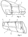
- Figs. 5-6 is shown in greater detail a dust container 16 suitable for use in a vacuum cleaner of stick or upright type. Even though any type of dust container 16 could be used in this invention, the dust container 16 according to Fig 5-6 is especially preferable in that it comprises an air channel 11 from its lower portion 12 closest to the nozzle 3. Traditionally this air channel 11 is comprised in the stick of the vacuum cleaner.
- the solution according to Figs. 5-6 has the advantages that less sealings between the dust container 16 and the stick part 7 are needed, and that a small leakage does not affect the cleaning performance of the cleaner since the leakage would take place inside the dust separation container 16. Having the air channel outside the dust container requires much attention to the sealings and to the impermeability of the design.
- the dust separation chamber 5 in the dust container 16 in Figs. 5-6 is of cyclonic type.
- the fan unit 6 creates an air flow entering the dust container 16 at the inlet 12 of the air channel, which is positioned closest to the nozzle 3, and then entering the dust separation chamber 5 at the exit 13 of the air channel situated above its inlet 12, as seen in normal use of the cleaner 1.
- the air flow enters the dust separation chamber 5 tangentially, whereby a swirling motion of the air flow is created in the dust separation chamber 5.
- the swirling motion separates particles from the air flow, which particles are collected inside the dust container 16.
- a filter 14 is positioned.
- the filter 14 separates the fmer particles not already separated by the swirling motion.
- the filter could be of any kind, such as a frusto conical cup shaped two part filter 14, or a pleated cylindrical filter.
Landscapes
- Engineering & Computer Science (AREA)
- Mechanical Engineering (AREA)
- Filters For Electric Vacuum Cleaners (AREA)
Description
- The invention relates to a vacuum cleaner having two separate parts connectable to each other, according to the preamble of claim 1.
-
US 2008/0040883 discloses a vacuum cleaner according to the preamble of claim 1. - It is known since long that batteries used for driving a vacuum cleaner need to be cooled to be used as efficiently as possible and to last as long as possible. One way of cooling them is to lead the air flow created by the vacuum cleaner past the batteries.
- It has also been known since long to make stick or upright type vacuum cleaners in two parts connectable to each other in order to save space when the vacuum cleaner is stored or transported. Different solutions exist, such as making the vacuum cleaner in two separate parts connectable to each other by the user, or to make the vacuum cleaner in two different parts connected to each other via a knee joint such that the user can fold and unfold the cleaner in order to adapt it for cleaning purposes or for storing.
- There has also since long been a wish to increase the battery capacity to have a longer running time and to have enough power for the fan unit to create large air flows. Also with new battery technologies is has been difficult to fit enough batteries into the vacuum cleaners to reach the desired levels regarding running time and air flow.
- The purpose of this invention is to solve the problems mentioned above. This is achieved by a two part vacuum cleaner according to the preamble of claim 1 having an air outlet in the part of the vacuum cleaner comprising the handle.
- By having an air outlet in the part comprising the handle it is possible to have batteries also in this part, and still have a cooling air flow past the batteries. The batteries could thereby be placed in either of the vacuum cleaner parts, or in both.
- The housing of a vacuum cleaner of course comprises several different parts, but the expression "two main parts" here refers to two parts movable and connectable in relation to each other for facilitating storage and transport of the cleaner.
- The vacuum cleaner preferably further comprises a duct forming a portion of the flow path and extending, for example adjacent to a space for electric wiring, between the two parts. It preferably also comprises batteries for driving the vacuum cleaner placed after the fan unit in the part comprising the dust separation chamber and the fan unit, or in the part comprising the handle, or in both parts. The two parts are preferably adapted to be connected to each other by a user of the cleaner either by mounting one part into the other and locking them relative to each other by a suitable fastening means, or via a knee joint. The above mentioned embodiments give advantages in terms of manufacturing and usability and performance.
- Furthermore the vacuum cleaner comprises a dust container comprising an air channel extending from the part of the dust container closest to the nozzle to the inlet of the dust separation chamber. This embodiment is advantageous in that it gives few sealings between the dust container and the vacuum cleaner housing, and in that it gives a substantially impermeable construction, since possible leakage would take place inside the dust container.
- For illustrative purposes, an embodiment of the invention will now be described with reference to the drawings, on which
-
Fig. 1 is a schematic view of a vacuum cleaner according to the invention. -
Fig. 2 is a schematic view from below of the nozzle of the vacuum cleaner infig. 1 . -
Fig. 3 is a schematic view of the vacuum cleaner according to the invention with its two parts not yet mounted to each other. -
Fig. 4 is a schematic view from behind of a mid portion of a vacuum cleaner according to the invention. -
Fig. 5 is a schematic view of a dust container suitable for use in a vacuum cleaner according to the invention -
Fig. 6 is a schematic view of the dust container inFig. 5 from another angle. -
Figs. 1-4 show a vacuum cleaner 1 of stick type. It could of course also be a so called upright cleaner, and the stick could be of the type carrying a hand held vacuum cleaner with a dust container, or just a dust container. The vacuum cleaner 1 comprises ahousing 2, anozzle 3 with anair inlet 4, adust separation chamber 5, a fan unit 6 (in the drawings the fan unit is not explicitly shown, but one possible position for it is indicated) and at least oneair outlet 15. Thehousing 2 comprises twoseparate parts 7, 8 (see especiallyFig. 3 ) connectable to each other, of which onepart 7 comprises thedust separation chamber 5 and the fan unit 6, and theother part 8 comprises a handle for the stick or upright type vacuum cleaner 1. Anair outlet 15 is placed in thepart 8 comprising the handle. Air outlets could of course also be placed in thepart 7 comprising thedust separation chamber 5 and the fan unit 6. - In use, the the fan unit 6 creates an air flow in a flow path extending from the
air inlet 4 via thedust separation chamber 5 to theair outlet 15. In the embodiment inFig 1 thebatteries 10 are placed in thepart 7 comprising the fan unit 6 and thedust separation chamber 5, but it is of course also possible to place thebatteries 10 in thepart 8 comprising the handle, or in bothparts - Having an
air outlet 15 in thepart 8 comprising the handle allows having a cooling air flow past thebatteries 10 if placed in thispart 8. The air is preferably led in a duct 9 leading from one part to the other. Usually there is electric wiring going from one part to the other, and the duct 9 for the cooling air flow could preferably be placed adjacent to the passage for the electric wiring. - The vacuum cleaner 1 is of the type having two
separate parts parts - In
Figs. 5-6 is shown in greater detail adust container 16 suitable for use in a vacuum cleaner of stick or upright type. Even though any type ofdust container 16 could be used in this invention, thedust container 16 according toFig 5-6 is especially preferable in that it comprises anair channel 11 from itslower portion 12 closest to thenozzle 3. Traditionally thisair channel 11 is comprised in the stick of the vacuum cleaner. The solution according toFigs. 5-6 has the advantages that less sealings between thedust container 16 and thestick part 7 are needed, and that a small leakage does not affect the cleaning performance of the cleaner since the leakage would take place inside thedust separation container 16. Having the air channel outside the dust container requires much attention to the sealings and to the impermeability of the design. - The
dust separation chamber 5 in thedust container 16 inFigs. 5-6 is of cyclonic type. In use the fan unit 6 creates an air flow entering thedust container 16 at theinlet 12 of the air channel, which is positioned closest to thenozzle 3, and then entering thedust separation chamber 5 at theexit 13 of the air channel situated above itsinlet 12, as seen in normal use of the cleaner 1. The air flow enters thedust separation chamber 5 tangentially, whereby a swirling motion of the air flow is created in thedust separation chamber 5. The swirling motion separates particles from the air flow, which particles are collected inside thedust container 16. At theoutlet 13 of thedust separation chamber 5, afilter 14 is positioned. Thefilter 14 separates the fmer particles not already separated by the swirling motion. The filter could be of any kind, such as a frusto conical cup shaped twopart filter 14, or a pleated cylindrical filter.
Claims (6)
- Vacuum cleaner (1) of stick or upright type, which vacuum cleaner (1) comprises a housing (2), a nozzle (3) with an air inlet (4), a dust separation chamber (5), a fan unit (6) and at least one air outlet, whereby the fan unit (6) is adapted to create an air flow in a flow path extending from the air inlet (4) via the dust separation chamber (5) to the air outlet, and whereby the housing (2) comprises two main parts (7, 8) connectable to each other, of which one part (7) comprises the dust separation chamber (5) and the fan unit (6), and the other part (8) comprises a handle for the stick or upright type vacuum cleaner (1), characterised in that at least one air outlet (15) is placed in the part (8) comprising the handle such that air flows past batteries (10) placed in this part (8).
- Vacuum cleaner (1) according to claim 1, characterised in that it comprises a duct (9) forming a portion of the flow path and extending between the two parts (7, 8).
- Vacuum cleaner (1) according to claim 1 or 2, characterised in that batteries (10) for driving the vacuum cleaner (1) are placed after the fan unit (6) in the part (7) comprising the dust separation chamber (5) and the fan unit (6), or in the part (8) comprising the handle, or in both parts (7, 8).
- Vacuum cleaner (1) according to any of claims 1-3, characterised in that the two parts (7, 8) are adapted to be connected to each other by a user of the cleaner by mounting one part into the other and locking them relative to each other by a suitable fastening means.
- Vacuum cleaner (1) according to any of claims 1-3, characterised in that the two parts (7, 8) are connected to each other via a knee joint.
- Vacuum cleaner (1) according to any of claims 1-5, characterised in that it comprises a dust container (16) comprising an air channel (11) extending from the part of the dust container (16) closest to the nozzle to the inlet of the dust separation chamber (5).
Applications Claiming Priority (3)
| Application Number | Priority Date | Filing Date | Title |
|---|---|---|---|
| SE0802182 | 2008-10-10 | ||
| US10608008P | 2008-10-16 | 2008-10-16 | |
| PCT/EP2009/007207 WO2010040523A1 (en) | 2008-10-10 | 2009-10-08 | Vacuum cleaner air outlet |
Publications (2)
| Publication Number | Publication Date |
|---|---|
| EP2355684A1 EP2355684A1 (en) | 2011-08-17 |
| EP2355684B1 true EP2355684B1 (en) | 2013-03-20 |
Family
ID=41401807
Family Applications (1)
| Application Number | Title | Priority Date | Filing Date |
|---|---|---|---|
| EP09736836A Active EP2355684B1 (en) | 2008-10-10 | 2009-10-08 | Vacuum cleaner air outlet |
Country Status (4)
| Country | Link |
|---|---|
| US (1) | US8572801B2 (en) |
| EP (1) | EP2355684B1 (en) |
| CN (1) | CN102245071B (en) |
| WO (1) | WO2010040523A1 (en) |
Families Citing this family (12)
| Publication number | Priority date | Publication date | Assignee | Title |
|---|---|---|---|---|
| DE102012206624A1 (en) * | 2012-04-23 | 2013-10-24 | Robert Bosch Gmbh | System with a vacuum cleaner and a hand vacuum cleaner |
| US9775484B2 (en) * | 2013-03-01 | 2017-10-03 | Omachron Intellectual Property Inc. | Surface cleaning apparatus |
| US9655485B2 (en) | 2013-12-18 | 2017-05-23 | Aktiebolaget Electrolux | Vacuum cleaner suction nozzle with height adjustment and bleed valve |
| GB2527127A (en) * | 2014-06-13 | 2015-12-16 | Techtronic Ind Co Ltd | Apparatus for cleaning a floor surface |
| WO2016061521A1 (en) * | 2014-10-16 | 2016-04-21 | Techtronic Industries Co. Ltd. | Improved battery removal for a vacuum cleaner |
| CN105615766A (en) * | 2014-11-03 | 2016-06-01 | 康塔有限公司 | Ground cleaning equipment |
| US9756999B2 (en) | 2014-12-22 | 2017-09-12 | Aktiebolaget Electrolux | Vacuum cleaner filtration system with filter cleaning mode |
| KR20190058501A (en) * | 2016-10-07 | 2019-05-29 | 에이비 엘렉트로룩스 | Filters with improved filters Vacuum cleaners |
| DE102017208965A1 (en) | 2017-05-29 | 2018-11-29 | BSH Hausgeräte GmbH | Blow-out channel for a vacuum cleaner and vacuum cleaner having this blow-out |
| DE102017222735A1 (en) * | 2017-12-14 | 2019-06-19 | Vorwerk & Co. Interholding Gmbh | Vacuum cleaner with battery |
| USD1013989S1 (en) * | 2021-04-01 | 2024-02-06 | Cixi Mongsun Electric Appliance Co., Ltd | Vacuum cleaner |
| US12478230B2 (en) | 2022-07-07 | 2025-11-25 | Bissell Inc. | Modular head system for handheld extraction cleaner, dry vacuum accessory for handheld extraction cleaner, and handheld extraction cleaner |
Family Cites Families (5)
| Publication number | Priority date | Publication date | Assignee | Title |
|---|---|---|---|---|
| CN2596931Y (en) * | 2002-12-20 | 2004-01-07 | 彭锐智 | Mop with vacuum cleaner |
| US7137169B2 (en) * | 2003-01-10 | 2006-11-21 | Royal Appliance Mfg. Co. | Vacuum cleaner with cleaning pad |
| US20070136984A1 (en) | 2005-12-15 | 2007-06-21 | Zweita International Co., Ltd. | Rechargeable vacuum cleaner |
| US20080040883A1 (en) | 2006-04-10 | 2008-02-21 | Jonas Beskow | Air Flow Losses in a Vacuum Cleaners |
| CN201001701Y (en) * | 2006-12-05 | 2008-01-09 | 方焕成 | Novel mop |
-
2009
- 2009-10-08 WO PCT/EP2009/007207 patent/WO2010040523A1/en not_active Ceased
- 2009-10-08 US US13/124,236 patent/US8572801B2/en not_active Expired - Fee Related
- 2009-10-08 EP EP09736836A patent/EP2355684B1/en active Active
- 2009-10-08 CN CN200980149757.4A patent/CN102245071B/en active Active
Also Published As
| Publication number | Publication date |
|---|---|
| US20120124770A1 (en) | 2012-05-24 |
| WO2010040523A1 (en) | 2010-04-15 |
| CN102245071A (en) | 2011-11-16 |
| EP2355684A1 (en) | 2011-08-17 |
| CN102245071B (en) | 2014-05-28 |
| US8572801B2 (en) | 2013-11-05 |
Similar Documents
| Publication | Publication Date | Title |
|---|---|---|
| US8572801B2 (en) | Vacuum cleaner air outlet | |
| US20200129024A1 (en) | Vacuum cleaner combination and stick vacuum cleaner | |
| US4451951A (en) | Engine-driven blower/dust collector | |
| CN103536244B (en) | vacuum cleaner | |
| US10363565B2 (en) | Portable cyclone dust separator and corresponding dedusting system | |
| SE531125C2 (en) | Improvements in air flow losses in a vacuum cleaner | |
| CA2553412A1 (en) | Hand-holdable vacuum cleaners | |
| US20230371764A1 (en) | Handheld Vacuum Cleaner With Removable Filter | |
| WO2005041739B1 (en) | Vacuum cleaner with cyclonic dirt separation and bottom discharge dirt cup with filter | |
| WO2007104238A1 (en) | Portable cleaner | |
| EP3795049B1 (en) | Vacuum cleaner | |
| US20060156504A1 (en) | Central vacuum system with secondary airflow path | |
| CN112168057A (en) | Vacuum cleaner | |
| JP2007229470A (en) | Dust separator and vacuum cleaner provided with the same | |
| GB2456193A (en) | Dual cyclonic dust collector | |
| CN104042166B (en) | Electric Cleaner | |
| CN101282674A (en) | Dust collection device for vacuum cleaner | |
| WO2006102147A3 (en) | Twin cyclone vacuum cleaner | |
| JP5488204B2 (en) | Cyclone separation device and vacuum cleaner provided with the same | |
| US20100313378A1 (en) | Upright-type vacuum cleaner | |
| JP2012061093A (en) | Dust separating/collecting container and vacuum cleaner | |
| US11627851B2 (en) | Separating device for a vacuuming device | |
| JP6548932B2 (en) | Dust separation device and vacuum cleaner | |
| US11337570B2 (en) | Stick vacuum cleaner with improved filter | |
| CA2738294C (en) | Vacuum cleaner |
Legal Events
| Date | Code | Title | Description |
|---|---|---|---|
| PUAI | Public reference made under article 153(3) epc to a published international application that has entered the european phase |
Free format text: ORIGINAL CODE: 0009012 |
|
| 17P | Request for examination filed |
Effective date: 20110510 |
|
| AK | Designated contracting states |
Kind code of ref document: A1 Designated state(s): AT BE BG CH CY CZ DE DK EE ES FI FR GB GR HR HU IE IS IT LI LT LU LV MC MK MT NL NO PL PT RO SE SI SK SM TR |
|
| RIN1 | Information on inventor provided before grant (corrected) |
Inventor name: ENGSTROEM, CHRISTER Inventor name: DANESTAD, ULRIK |
|
| DAX | Request for extension of the european patent (deleted) | ||
| GRAP | Despatch of communication of intention to grant a patent |
Free format text: ORIGINAL CODE: EPIDOSNIGR1 |
|
| GRAS | Grant fee paid |
Free format text: ORIGINAL CODE: EPIDOSNIGR3 |
|
| GRAA | (expected) grant |
Free format text: ORIGINAL CODE: 0009210 |
|
| AK | Designated contracting states |
Kind code of ref document: B1 Designated state(s): AT BE BG CH CY CZ DE DK EE ES FI FR GB GR HR HU IE IS IT LI LT LU LV MC MK MT NL NO PL PT RO SE SI SK SM TR |
|
| REG | Reference to a national code |
Ref country code: GB Ref legal event code: FG4D |
|
| REG | Reference to a national code |
Ref country code: CH Ref legal event code: EP |
|
| REG | Reference to a national code |
Ref country code: IE Ref legal event code: FG4D |
|
| REG | Reference to a national code |
Ref country code: AT Ref legal event code: REF Ref document number: 601526 Country of ref document: AT Kind code of ref document: T Effective date: 20130415 |
|
| REG | Reference to a national code |
Ref country code: DE Ref legal event code: R096 Ref document number: 602009014195 Country of ref document: DE Effective date: 20130516 |
|
| PG25 | Lapsed in a contracting state [announced via postgrant information from national office to epo] |
Ref country code: SE Free format text: LAPSE BECAUSE OF FAILURE TO SUBMIT A TRANSLATION OF THE DESCRIPTION OR TO PAY THE FEE WITHIN THE PRESCRIBED TIME-LIMIT Effective date: 20130320 Ref country code: LT Free format text: LAPSE BECAUSE OF FAILURE TO SUBMIT A TRANSLATION OF THE DESCRIPTION OR TO PAY THE FEE WITHIN THE PRESCRIBED TIME-LIMIT Effective date: 20130320 Ref country code: ES Free format text: LAPSE BECAUSE OF FAILURE TO SUBMIT A TRANSLATION OF THE DESCRIPTION OR TO PAY THE FEE WITHIN THE PRESCRIBED TIME-LIMIT Effective date: 20130701 Ref country code: BG Free format text: LAPSE BECAUSE OF FAILURE TO SUBMIT A TRANSLATION OF THE DESCRIPTION OR TO PAY THE FEE WITHIN THE PRESCRIBED TIME-LIMIT Effective date: 20130620 Ref country code: NO Free format text: LAPSE BECAUSE OF FAILURE TO SUBMIT A TRANSLATION OF THE DESCRIPTION OR TO PAY THE FEE WITHIN THE PRESCRIBED TIME-LIMIT Effective date: 20130620 |
|
| REG | Reference to a national code |
Ref country code: AT Ref legal event code: MK05 Ref document number: 601526 Country of ref document: AT Kind code of ref document: T Effective date: 20130320 |
|
| REG | Reference to a national code |
Ref country code: LT Ref legal event code: MG4D |
|
| PG25 | Lapsed in a contracting state [announced via postgrant information from national office to epo] |
Ref country code: SI Free format text: LAPSE BECAUSE OF FAILURE TO SUBMIT A TRANSLATION OF THE DESCRIPTION OR TO PAY THE FEE WITHIN THE PRESCRIBED TIME-LIMIT Effective date: 20130320 Ref country code: LV Free format text: LAPSE BECAUSE OF FAILURE TO SUBMIT A TRANSLATION OF THE DESCRIPTION OR TO PAY THE FEE WITHIN THE PRESCRIBED TIME-LIMIT Effective date: 20130320 Ref country code: GR Free format text: LAPSE BECAUSE OF FAILURE TO SUBMIT A TRANSLATION OF THE DESCRIPTION OR TO PAY THE FEE WITHIN THE PRESCRIBED TIME-LIMIT Effective date: 20130621 Ref country code: FI Free format text: LAPSE BECAUSE OF FAILURE TO SUBMIT A TRANSLATION OF THE DESCRIPTION OR TO PAY THE FEE WITHIN THE PRESCRIBED TIME-LIMIT Effective date: 20130320 |
|
| REG | Reference to a national code |
Ref country code: NL Ref legal event code: VDEP Effective date: 20130320 |
|
| PG25 | Lapsed in a contracting state [announced via postgrant information from national office to epo] |
Ref country code: HR Free format text: LAPSE BECAUSE OF FAILURE TO SUBMIT A TRANSLATION OF THE DESCRIPTION OR TO PAY THE FEE WITHIN THE PRESCRIBED TIME-LIMIT Effective date: 20130320 Ref country code: BE Free format text: LAPSE BECAUSE OF FAILURE TO SUBMIT A TRANSLATION OF THE DESCRIPTION OR TO PAY THE FEE WITHIN THE PRESCRIBED TIME-LIMIT Effective date: 20130320 |
|
| PG25 | Lapsed in a contracting state [announced via postgrant information from national office to epo] |
Ref country code: SK Free format text: LAPSE BECAUSE OF FAILURE TO SUBMIT A TRANSLATION OF THE DESCRIPTION OR TO PAY THE FEE WITHIN THE PRESCRIBED TIME-LIMIT Effective date: 20130320 Ref country code: IS Free format text: LAPSE BECAUSE OF FAILURE TO SUBMIT A TRANSLATION OF THE DESCRIPTION OR TO PAY THE FEE WITHIN THE PRESCRIBED TIME-LIMIT Effective date: 20130720 Ref country code: NL Free format text: LAPSE BECAUSE OF FAILURE TO SUBMIT A TRANSLATION OF THE DESCRIPTION OR TO PAY THE FEE WITHIN THE PRESCRIBED TIME-LIMIT Effective date: 20130320 Ref country code: PT Free format text: LAPSE BECAUSE OF FAILURE TO SUBMIT A TRANSLATION OF THE DESCRIPTION OR TO PAY THE FEE WITHIN THE PRESCRIBED TIME-LIMIT Effective date: 20130722 Ref country code: CZ Free format text: LAPSE BECAUSE OF FAILURE TO SUBMIT A TRANSLATION OF THE DESCRIPTION OR TO PAY THE FEE WITHIN THE PRESCRIBED TIME-LIMIT Effective date: 20130320 Ref country code: RO Free format text: LAPSE BECAUSE OF FAILURE TO SUBMIT A TRANSLATION OF THE DESCRIPTION OR TO PAY THE FEE WITHIN THE PRESCRIBED TIME-LIMIT Effective date: 20130320 Ref country code: AT Free format text: LAPSE BECAUSE OF FAILURE TO SUBMIT A TRANSLATION OF THE DESCRIPTION OR TO PAY THE FEE WITHIN THE PRESCRIBED TIME-LIMIT Effective date: 20130320 Ref country code: EE Free format text: LAPSE BECAUSE OF FAILURE TO SUBMIT A TRANSLATION OF THE DESCRIPTION OR TO PAY THE FEE WITHIN THE PRESCRIBED TIME-LIMIT Effective date: 20130320 |
|
| PG25 | Lapsed in a contracting state [announced via postgrant information from national office to epo] |
Ref country code: CY Free format text: LAPSE BECAUSE OF FAILURE TO SUBMIT A TRANSLATION OF THE DESCRIPTION OR TO PAY THE FEE WITHIN THE PRESCRIBED TIME-LIMIT Effective date: 20130320 Ref country code: PL Free format text: LAPSE BECAUSE OF FAILURE TO SUBMIT A TRANSLATION OF THE DESCRIPTION OR TO PAY THE FEE WITHIN THE PRESCRIBED TIME-LIMIT Effective date: 20130320 |
|
| PLBI | Opposition filed |
Free format text: ORIGINAL CODE: 0009260 |
|
| PLAX | Notice of opposition and request to file observation + time limit sent |
Free format text: ORIGINAL CODE: EPIDOSNOBS2 |
|
| PG25 | Lapsed in a contracting state [announced via postgrant information from national office to epo] |
Ref country code: DK Free format text: LAPSE BECAUSE OF FAILURE TO SUBMIT A TRANSLATION OF THE DESCRIPTION OR TO PAY THE FEE WITHIN THE PRESCRIBED TIME-LIMIT Effective date: 20130320 |
|
| 26 | Opposition filed |
Opponent name: STANLEY BLACK & DECKER, INC. Effective date: 20131220 |
|
| PG25 | Lapsed in a contracting state [announced via postgrant information from national office to epo] |
Ref country code: IT Free format text: LAPSE BECAUSE OF FAILURE TO SUBMIT A TRANSLATION OF THE DESCRIPTION OR TO PAY THE FEE WITHIN THE PRESCRIBED TIME-LIMIT Effective date: 20130320 |
|
| REG | Reference to a national code |
Ref country code: DE Ref legal event code: R026 Ref document number: 602009014195 Country of ref document: DE Effective date: 20131220 |
|
| PLAF | Information modified related to communication of a notice of opposition and request to file observations + time limit |
Free format text: ORIGINAL CODE: EPIDOSCOBS2 |
|
| PG25 | Lapsed in a contracting state [announced via postgrant information from national office to epo] |
Ref country code: MC Free format text: LAPSE BECAUSE OF FAILURE TO SUBMIT A TRANSLATION OF THE DESCRIPTION OR TO PAY THE FEE WITHIN THE PRESCRIBED TIME-LIMIT Effective date: 20130320 |
|
| REG | Reference to a national code |
Ref country code: CH Ref legal event code: PL |
|
| PLBB | Reply of patent proprietor to notice(s) of opposition received |
Free format text: ORIGINAL CODE: EPIDOSNOBS3 |
|
| REG | Reference to a national code |
Ref country code: IE Ref legal event code: MM4A |
|
| PG25 | Lapsed in a contracting state [announced via postgrant information from national office to epo] |
Ref country code: LI Free format text: LAPSE BECAUSE OF NON-PAYMENT OF DUE FEES Effective date: 20131031 Ref country code: CH Free format text: LAPSE BECAUSE OF NON-PAYMENT OF DUE FEES Effective date: 20131031 |
|
| PG25 | Lapsed in a contracting state [announced via postgrant information from national office to epo] |
Ref country code: IE Free format text: LAPSE BECAUSE OF NON-PAYMENT OF DUE FEES Effective date: 20131008 |
|
| PG25 | Lapsed in a contracting state [announced via postgrant information from national office to epo] |
Ref country code: SM Free format text: LAPSE BECAUSE OF FAILURE TO SUBMIT A TRANSLATION OF THE DESCRIPTION OR TO PAY THE FEE WITHIN THE PRESCRIBED TIME-LIMIT Effective date: 20130320 |
|
| PG25 | Lapsed in a contracting state [announced via postgrant information from national office to epo] |
Ref country code: TR Free format text: LAPSE BECAUSE OF FAILURE TO SUBMIT A TRANSLATION OF THE DESCRIPTION OR TO PAY THE FEE WITHIN THE PRESCRIBED TIME-LIMIT Effective date: 20130320 |
|
| PG25 | Lapsed in a contracting state [announced via postgrant information from national office to epo] |
Ref country code: HU Free format text: LAPSE BECAUSE OF FAILURE TO SUBMIT A TRANSLATION OF THE DESCRIPTION OR TO PAY THE FEE WITHIN THE PRESCRIBED TIME-LIMIT; INVALID AB INITIO Effective date: 20091008 Ref country code: MK Free format text: LAPSE BECAUSE OF FAILURE TO SUBMIT A TRANSLATION OF THE DESCRIPTION OR TO PAY THE FEE WITHIN THE PRESCRIBED TIME-LIMIT Effective date: 20130320 Ref country code: LU Free format text: LAPSE BECAUSE OF NON-PAYMENT OF DUE FEES Effective date: 20131008 |
|
| PG25 | Lapsed in a contracting state [announced via postgrant information from national office to epo] |
Ref country code: MT Free format text: LAPSE BECAUSE OF FAILURE TO SUBMIT A TRANSLATION OF THE DESCRIPTION OR TO PAY THE FEE WITHIN THE PRESCRIBED TIME-LIMIT Effective date: 20130320 |
|
| REG | Reference to a national code |
Ref country code: FR Ref legal event code: PLFP Year of fee payment: 7 |
|
| REG | Reference to a national code |
Ref country code: DE Ref legal event code: R100 Ref document number: 602009014195 Country of ref document: DE |
|
| PLCK | Communication despatched that opposition was rejected |
Free format text: ORIGINAL CODE: EPIDOSNREJ1 |
|
| PLBN | Opposition rejected |
Free format text: ORIGINAL CODE: 0009273 |
|
| STAA | Information on the status of an ep patent application or granted ep patent |
Free format text: STATUS: OPPOSITION REJECTED |
|
| 27O | Opposition rejected |
Effective date: 20151112 |
|
| REG | Reference to a national code |
Ref country code: FR Ref legal event code: PLFP Year of fee payment: 8 |
|
| REG | Reference to a national code |
Ref country code: FR Ref legal event code: PLFP Year of fee payment: 9 |
|
| REG | Reference to a national code |
Ref country code: FR Ref legal event code: PLFP Year of fee payment: 10 |
|
| P01 | Opt-out of the competence of the unified patent court (upc) registered |
Effective date: 20230521 |
|
| PGFP | Annual fee paid to national office [announced via postgrant information from national office to epo] |
Ref country code: DE Payment date: 20241029 Year of fee payment: 16 |
|
| PGFP | Annual fee paid to national office [announced via postgrant information from national office to epo] |
Ref country code: GB Payment date: 20241022 Year of fee payment: 16 |
|
| PGFP | Annual fee paid to national office [announced via postgrant information from national office to epo] |
Ref country code: FR Payment date: 20241025 Year of fee payment: 16 |