EP2355485A2 - Data processor and scanner device - Google Patents
Data processor and scanner device Download PDFInfo
- Publication number
- EP2355485A2 EP2355485A2 EP10252156A EP10252156A EP2355485A2 EP 2355485 A2 EP2355485 A2 EP 2355485A2 EP 10252156 A EP10252156 A EP 10252156A EP 10252156 A EP10252156 A EP 10252156A EP 2355485 A2 EP2355485 A2 EP 2355485A2
- Authority
- EP
- European Patent Office
- Prior art keywords
- file
- images
- generating unit
- image
- maximum number
- Prior art date
- Legal status (The legal status is an assumption and is not a legal conclusion. Google has not performed a legal analysis and makes no representation as to the accuracy of the status listed.)
- Granted
Links
Images


Classifications
-
- H—ELECTRICITY
- H04—ELECTRIC COMMUNICATION TECHNIQUE
- H04N—PICTORIAL COMMUNICATION, e.g. TELEVISION
- H04N1/00—Scanning, transmission or reproduction of documents or the like, e.g. facsimile transmission; Details thereof
- H04N1/00127—Connection or combination of a still picture apparatus with another apparatus, e.g. for storage, processing or transmission of still picture signals or of information associated with a still picture
- H04N1/00132—Connection or combination of a still picture apparatus with another apparatus, e.g. for storage, processing or transmission of still picture signals or of information associated with a still picture in a digital photofinishing system, i.e. a system where digital photographic images undergo typical photofinishing processing, e.g. printing ordering
- H04N1/00185—Image output
- H04N1/00196—Creation of a photo-montage, e.g. photoalbum
-
- G—PHYSICS
- G06—COMPUTING OR CALCULATING; COUNTING
- G06F—ELECTRIC DIGITAL DATA PROCESSING
- G06F3/00—Input arrangements for transferring data to be processed into a form capable of being handled by the computer; Output arrangements for transferring data from processing unit to output unit, e.g. interface arrangements
- G06F3/12—Digital output to print unit, e.g. line printer, chain printer
- G06F3/1201—Dedicated interfaces to print systems
- G06F3/1202—Dedicated interfaces to print systems specifically adapted to achieve a particular effect
- G06F3/1203—Improving or facilitating administration, e.g. print management
-
- G—PHYSICS
- G06—COMPUTING OR CALCULATING; COUNTING
- G06F—ELECTRIC DIGITAL DATA PROCESSING
- G06F3/00—Input arrangements for transferring data to be processed into a form capable of being handled by the computer; Output arrangements for transferring data from processing unit to output unit, e.g. interface arrangements
- G06F3/12—Digital output to print unit, e.g. line printer, chain printer
- G06F3/1201—Dedicated interfaces to print systems
- G06F3/1223—Dedicated interfaces to print systems specifically adapted to use a particular technique
- G06F3/1237—Print job management
- G06F3/1253—Configuration of print job parameters, e.g. using UI at the client
- G06F3/1257—Configuration of print job parameters, e.g. using UI at the client by using pre-stored settings, e.g. job templates, presets, print styles
-
- H—ELECTRICITY
- H04—ELECTRIC COMMUNICATION TECHNIQUE
- H04N—PICTORIAL COMMUNICATION, e.g. TELEVISION
- H04N1/00—Scanning, transmission or reproduction of documents or the like, e.g. facsimile transmission; Details thereof
- H04N1/32—Circuits or arrangements for control or supervision between transmitter and receiver or between image input and image output device, e.g. between a still-image camera and its memory or between a still-image camera and a printer device
- H04N1/32101—Display, printing, storage or transmission of additional information, e.g. ID code, date and time or title
- H04N1/32128—Display, printing, storage or transmission of additional information, e.g. ID code, date and time or title attached to the image data, e.g. file header, transmitted message header, information on the same page or in the same computer file as the image
-
- G—PHYSICS
- G06—COMPUTING OR CALCULATING; COUNTING
- G06F—ELECTRIC DIGITAL DATA PROCESSING
- G06F3/00—Input arrangements for transferring data to be processed into a form capable of being handled by the computer; Output arrangements for transferring data from processing unit to output unit, e.g. interface arrangements
- G06F3/12—Digital output to print unit, e.g. line printer, chain printer
- G06F3/1201—Dedicated interfaces to print systems
- G06F3/1202—Dedicated interfaces to print systems specifically adapted to achieve a particular effect
- G06F3/1203—Improving or facilitating administration, e.g. print management
- G06F3/1205—Improving or facilitating administration, e.g. print management resulting in increased flexibility in print job configuration, e.g. job settings, print requirements, job tickets
-
- G—PHYSICS
- G06—COMPUTING OR CALCULATING; COUNTING
- G06F—ELECTRIC DIGITAL DATA PROCESSING
- G06F3/00—Input arrangements for transferring data to be processed into a form capable of being handled by the computer; Output arrangements for transferring data from processing unit to output unit, e.g. interface arrangements
- G06F3/12—Digital output to print unit, e.g. line printer, chain printer
- G06F3/1201—Dedicated interfaces to print systems
- G06F3/1202—Dedicated interfaces to print systems specifically adapted to achieve a particular effect
- G06F3/1203—Improving or facilitating administration, e.g. print management
- G06F3/1208—Improving or facilitating administration, e.g. print management resulting in improved quality of the output result, e.g. print layout, colours, workflows, print preview
-
- H—ELECTRICITY
- H04—ELECTRIC COMMUNICATION TECHNIQUE
- H04N—PICTORIAL COMMUNICATION, e.g. TELEVISION
- H04N2201/00—Indexing scheme relating to scanning, transmission or reproduction of documents or the like, and to details thereof
- H04N2201/32—Circuits or arrangements for control or supervision between transmitter and receiver or between image input and image output device, e.g. between a still-image camera and its memory or between a still-image camera and a printer device
- H04N2201/3201—Display, printing, storage or transmission of additional information, e.g. ID code, date and time or title
- H04N2201/3225—Display, printing, storage or transmission of additional information, e.g. ID code, date and time or title of data relating to an image, a page or a document
- H04N2201/3247—Data linking a set of images to one another, e.g. sequence, burst or continuous capture mode
Definitions
- the invention disclosed in this specification relates to a data processor that generates image files.
- One conventional data processor known in the art converts a scanned image to a file in a user-specified format (a JPEG file, a BMP file, a PDF file, or a TIFF file, for example) and outputs the resulting file.
- this data processor can generate either N image files (i.e., one image file for each scanned image) or a single file having data for the N scanned images arranged in N pages.
- the data processor includes an image acquiring unit, a reference file acquiring unit, and a file generating unit.
- the image acquiring unit is configured to acquire a plurality of sets of image data indicating a plurality of images.
- the reference file acquiring unit is configured to acquire a reference file including a reference object including first information indicating a layout of at least two images among the plurality of images.
- the file generating unit is configured to generate a file in which the plurality of images are laid out based on the first information.
- the invention provides a scanner device.
- the scanner device includes a scanning unit, an image acquiring unit, a reference file acquiring unit, and a file generating unit.
- the scanning unit is configured to scan a plurality of images and generates a plurality of sets of image data indicating the plurality of images.
- the image acquiring unit is configured to acquire the plurality of sets of image data.
- the reference file acquiring unit is configured to acquire a reference file including a reference object including first information indicating a layout of at least two images among the plurality of images.
- the file generating unit is configured to generate a file in which the plurality of images are laid out based on the first information.
- Fig. 1 is a block diagram showing a general structure of a network system according to a first embodiment
- Fig. 2 is a flowchart illustrating a part of a new file generation process according to the first embodiment
- Fig. 3 is a flowchart illustrating a remaining part of the new file generating process shown in Fig. 2 ;
- Fig. 4 is an explanatory diagram illustrating a reference file of a first example
- Fig. 5 is an explanatory diagram illustrating a new file generated based on the reference file shown in Fig. 4 ;
- Fig. 6 is an explanatory diagram illustrating a reference file of a second example
- Fig. 7 is an explanatory diagram illustrating a new file generated based on the reference file shown in Fig. 6 ;
- Fig. 8 is an explanatory diagram illustrating a reference file of a third example
- Fig. 9 is an explanatory diagram illustrating a new file generated based on the reference file shown in Fig. 8 ;
- Fig. 10 is an explanatory diagram illustrating a reference file of a fourth example
- Fig. 11 is an explanatory diagram illustrating a new file generated based on the reference file shown in Fig. 10 ;
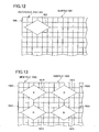
- Fig. 12 is an explanatory diagram illustrating a reference file of a fifth example.
- Fig. 13 is an explanatory diagram illustrating a new file generated based on the reference file shown in Fig. 12 .
- Fig. 1 is a block diagram showing a general structure of a network system 2 according to the embodiment.
- the network system 2 includes a local area network (LAN) 4, a multifunction device 10, and a personal computer (PC) 60.
- the multifunction device 10 and the PC 60 are connected to the LAN 4 and are capable of communicating with each other via the LAN 4.
- the multifunction device 10 has a plurality of functions, such as a copier function, printer function, scanner function, e-mail transmission/reception function, and Internet facsimile function. As shown in Fig. 1 , the multifunction device 10 includes an operating unit 12, a display unit 14, a network interface 16, a scanner unit 18, a printing unit 20, a USB interface 22, a memory unit 24, and a control unit 40.
- the operating unit 12 has a plurality of keys. A user operates the keys in the operating unit 12 to input a variety of instructions into the multifunction device 10.
- the display unit 14 functions to display various types of information.
- the network interface 16 functions to connect the multifunction device 10 to the LAN 4.
- the scanner unit 18 has a compact image sensor (CIS) or a charge-coupled device (CCD) scanning mechanism, for example, and functions to generate image data by scanning a target image.
- the printing unit 20 has an inkjet head or a laser printing mechanism, for example, and functions to print images according to instructions received from the control unit 40.
- the USB interface 22 enables connection of a USB memory device or a USB cable, for example.
- the memory unit 24 has a program storage area 26, a reference file storage area 28, and a new file storage area 30.
- the program storage area 26 stores programs 261.
- the control unit 40 executes various processes according to the programs 261 stored in the memory unit 24 in order to implement the functions of a reference file acquiring unit 42, an image acquiring unit 44, and a file generating unit 46. described later.
- the reference file storage area 28 is for storing reference files 100, 300, 500, 700, and 900 described later with reference to Figs. 4 , 6 , 8 , 10 , and 12 .
- the new file storage area 30 is for storing new files 200, 400, 600, 800, and 1000 described later with reference to Figs. 5 , 7 , 9 , 11 , and 13 based on the reference files stored in the reference file storage area 28.
- the reference files stored in the reference file storage area 28 are created in advance by the user through operations on the PC 60. These reference files are then stored in the reference file storage area 28 through user operations. New files are generated when the multifunction device 10 executes a new file generation process described below with reference to Figs. 2 and 3 and are stored in the new file storage area 30.
- the control unit 40 executes the new file generation process when the power to the multifunction device 10 is turned on.
- the control unit 40 begins monitoring user input to determine whether the user has performed an operation to select a reference file (the reference file 100 in Fig. 4 , for example) from the reference file storage area 28.
- the user can perform this selecting operation by operating the operating unit 12 of the multifunction device 10 or an operating unit of the PC 60 (not shown).
- the control unit 40 reaches a YES determination in S2 when the user selects a reference file. The following description will be based on a case in which the user has selected the reference file 100 of Fig. 4 in S2.
- the reference file acquiring unit 42 (see Fig. 1 ) reads and acquires the reference file 100 selected in S2 from the reference file storage area 28.
- the reference file 100 in the embodiment includes one or more subfiles 101.
- the subfile 101 includes a sheet extending horizontal and vertical direction.
- the subfile 101 (the sheet) has a plurality of cells 104 arranged in a grid with vertical columns and horizontal rows.
- An example of the reference file 100 having this structure is a file produced with the Microsoft Excel (registered trademark) program.
- a single reference image 102 is arranged in each subfile 101.
- the reference image 102 has a rectangular shape, with its horizontal sides longer than its vertical sides.
- the reference image 102 is arranged in a cell group 106 configured of six cells.
- the cell group 106 in which the reference image 102 is arranged will be referred to as the "first cell group.”
- the reference image 102 occupies only the center region of the first cell group 106.
- a margin is formed between the outline of the reference image 102 and the outline of the first cell group 106.
- the margin includes spaces Sp1a and Sp1b extending horizontally, and spaces Sp2a and Sp2b extending vertically.
- the reference image 102 also includes attribute data 108.
- the attribute data 108 is data that the user inputs in advance.
- the user generates a reference file 100 by specifying an image including the attribute data 108 as the reference image 102 and arranging the reference image 102 in the desired first cell group 106.
- the attribute data 108 includes data elements 109a, 109b, and 109c, and layout data 110.
- the data element 109a indicates the resolution of the reference image 102.
- the data element 109b indicates the data size of the reference image 102.
- the data element 109c indicates the date on which the reference image 102 was generated.
- the types of data elements 109a-109c are merely examples, and the attribute data 108 may include data other than these types.
- the attribute data 108 need not include all of the data elements 109a-109c, but should include at least one of the data elements 109a-109c in addition to the layout data 110.
- the attribute data 108 may alternatively be called "metadata.”
- the layout data 110 includes data elements 120, 122, and 124.
- the data elements 120, 122, and 124 relate to the layout for a plurality of images that is used in the new file generation process to generate a new file 200 (see Fig. 5 ) based on the reference file 100.
- the content of the layout data 110 will be described later in greater detail.
- the reference file acquiring unit 42 acquires the layout data 110 included in the reference file 100 that was acquired in S4.
- the reference file acquiring unit 42 identifies the position and size of the size of a region of the first cell group 106 (herein after "the size of the region of the cell group is referred to as simply "the size of the cell group") in the reference file 100 acquired in S4 in which the reference image 102 is arranged.
- the reference file acquiring unit 42 identifies the position of the first cell group 106 by identifying the position of an upper leftmost cell 104a constituting the first cell group 106. Using the example of Fig.
- the reference file acquiring unit 42 identifies the cell positioned second from the top and second from the left as the position of the upper leftmost cell 104a.
- the reference file acquiring unit 42 identifies the size of the first cell group 106 by identifying the number of cells constituting the first cell group 106 in the horizontal direction (three cells in the example of Fig. 4 ) and the number of cells constituting the first cell group 106 in the vertical direction (two cells in the example of Fig. 4 ).
- the position of the first cell group 106 identified in S8 will also be the position of a cell group 220 serving as the location in the new file 200 for arranging a single image 210.
- the cell group 220 of the new file 200 in which the image 210 is arranged will be referred to as a "second cell group.”
- the size of the first cell group 106 identified in S8 will also be the size of the second cell groups (the second cell group 220, etc.) in the new file 200.
- the reference file acquiring unit 42 identifies the layout area of the first cell group 106 identified in S8 in which the reference image 102 is arranged. More specifically, in S10 the reference file acquiring unit 42 identifies the spaces Sp1a, Sp1b, Sp2a, and Sp2b between each side constituting the outline of the first cell group 106 and the corresponding side constituting the outline of the reference image 102. Identifying the size of the first cell group 106 in S8 and identifying the spaces Sp1a, Sp1b, Sp2a, and Sp2b in S10 is equivalent to identifying the layout size of the reference image 102 (the horizontal and vertical dimensions of the reference image 102).
- the layout area of the reference image 102 identified in S10 will also serve as the layout area for arranging each image in the new file 200.
- the process advances to S30 of Fig. 3 .
- the control unit 40 In S30 of Fig. 3 , the control unit 40 generates an empty file as a base for creating a new file.
- the empty file is a newly generated file that includes no images, text, or other data.
- the empty file generated in S30 includes one subfile having a sheet and a plurality of cells.
- the control unit 40 executes an image layout process in S32-S52. Specifically, in S32 the control unit 40 monitors user input for a scan instruction. The user can input a scan instruction into the multifunction device 10 by operating the operating unit 12 of the multifunction device 10 after setting one scan target (one sheet of an original, for example) in an automatic document feeder (ADF; not shown), for example.
- ADF automatic document feeder
- the control unit 40 Upon detecting a scan instruction (S32: YES), the control unit 40 advances to S34.
- the image acquiring unit 44 controls the scanner unit 18 to scan the scan target.
- the image acquiring unit 44 acquires scan data for one image (hereinafter, scan data for an image will simply be called an "image").
- the file generating unit 46 determines whether the number of images in the subfile that is currently the process target has reached the maximum number of images that can be arranged in a single subfile (a single sheet). While this will be described in greater detail later, the layout data 110 acquired in S6 of Fig. 2 includes the data element 122 indicating the maximum number of images that can be arranged in a single subfile (the single sheet). The file generating unit 46 compares the maximum number indicated by the data element 122 to the number of images currently arranged in the target subfile and reaches a YES determination in S38 when the two numbers are equal.
- target subfile denotes a subfile that was generated in S30 during the period after a subfile was generated in S30 and until a new subfile is generated in S40. After a new subfile is generated in S40, the target subfile denotes this new subfile.
- the file generating unit 46 When the number of scanned images in the target subfile equals the maximum number (S38: YES), in S40 the file generating unit 46 generates a new subfile to be included in the file generated in S30. After the file generating unit 46 completes the process in S40 or reaches a No determination in S38, the process advances to S42.
- the file generating unit 46 identifies the second cell group for laying out the image acquired in S36 in the sheet of the target subfile. The process in S42 will be described later in greater detail.
- the file generating unit 46 arranges the image acquired in S36 in the second cell group identified in S42. The process in S44 will also be described later in greater detail. Subsequently, the process advances to S46.
- the file generating unit 46 determines whether the layout data 110 acquired in S6 of Fig. 2 includes information for arranging characters and the like (hereinafter referred to as "layout information"). The layout information will be described later in greater detail. If the layout data 110 includes layout information (S46: YES), in S48 the file generating unit 46 identifies the cell group in which the characters and the like are to be laid out. In S50 the file generating unit 46 lays out the characters and the like in the cell group identified in S48. After the file generating unit 46 completes the process in S50 or reaches a NO determination in S46, the process advances to S52.
- layout information information for arranging characters and the like
- the file generating unit 46 determines whether the user has performed an operation to end the image layout process. The user can perform this operation on the operating unit 12 of the multifunction device 10. If the file generating unit 46 determines that an operation to end the image layout process was performed (S52: YES), then the image layout process is ended and the file generating unit 46 advances to S54.
- the file generating unit 46 returns to S32 and monitors user input for a new scan instruction.
- the user may replace the scan target (original) set in the ADF for the previous image layout process with a new scan target and subsequently input a scan instruction in the multifunction device 10.
- the control unit 40 again reaches a YES determination in S32, and repeats the process in S32-S52 for laying out a new image in the subfile.
- the file generating unit 46 executes a process to end creation of a new file. Specifically, in S54 the file generating unit 46 stores the new file having one or more images laid out through one or more image layout processes in the new file storage area 30 (see Fig. 1 ). After completing the process to end new file creation in S54, the current process ends.
- the user can access the new file storage area 30 in the multifunction device 10 through operations on an operating unit of the PC 60, for example.
- the control unit 40 supplies the new file stored in the new file storage area 30 in S54 to the PC 60 (i.e., the user of the PC 60), thereby allowing the user to access the new file. Examples of Reference Files and New Files
- the layout data 110 included in the reference file 100 shown in Fig. 4 has the data elements 120, 122, and 124.
- the combination of " ⁇ Step>" specified by the data element 120 and " ⁇ /Step>” specified by the data element 124 signifies that a plurality of images are to be arranged vertically. That is, the data elements 120 and 124 define a step command instructing to lay out images vertically.
- the data elements 120 and 124 will also be called “step.”
- " ⁇ Max>3 ⁇ /Max>” specified by the data element 122 and 124 signifies that the maximum number of images to be arranged in one subfile is "3".
- the data element 122 (“ ⁇ Max>3 ⁇ /Max>") is located between the data elements 122 and 124, the number of images specified by the data element 122 are to be arranged vertically in one subfile.
- the maximum number is used in S38 of Fig. 4 .
- the data elements 120, 122, and 124 in this example indicate that a maximum number of three images are to be arranged vertically in one subfile.
- Fig. 5 shows an example of the new file 200 created based on the reference file 100 in Fig. 4 .
- the method of generating the new file 200 according to the process in Figs. 2 and 3 will be described next.
- the control unit 40 first creates a subfile 202 without any of the images 210, 212, or 214 shown in Fig. 5 .
- the subfile 202 has a plurality of cells 201 arranged in a grid with vertical columns and horizontal rows. Thus, when the process arrives at S38 the first time, the number of images arranged in the subfile 202 is "0".
- the file generating unit 46 reaches a NO determination in S38 since the maximum number indicated by the data element 122 in the layout data 110 is "3".
- the file generating unit 46 identifies the position of the first cell group 106 identified in S8 of Fig. 2 (the position of the upper leftmost cell 104a constituting the first cell group 106) as the location of the second cell group 220 for laying out an image.
- the file generating unit 46 identifies the size of the first cell group 106 identified in S8 of Fig. 2 (three cells horizontally by two cells vertically) as the size of the second cell group 220 for laying out an image.
- the file generating unit 46 Upon arriving at S44 for the first time, the file generating unit 46 lays out the image 210 acquired in the first execution of S36 in the second cell group 220. At this time, the file generating unit 46 arranges the image 210 so that the space between each side constituting the outline of the second cell group 220 and each corresponding side constituting the outline of the image 210 matches the spaces Sp1a, Sp1b, Sp2a, and Sp2b identified in S10 of Fig. 2 . Consequently, the layout size of the image 210 is identical to the layout size of the reference image 102.
- the file generating unit 46 also reaches a NO determination in the second execution of S38. Since the file generating unit 46 knows that a plurality of images are to be laid out vertically (i.e., stepped) based on the data elements 120 and 124 in the layout data 110 acquired in S6 of Fig. 2 , in the second execution of S42 the file generating unit 46 identifies a new second cell group 222 abutting the lower edge constituting the contour of the second cell group 220 identified in the first execution of S42. The horizontal position of the new second cell group 222 is identical to that of the second cell group 220. Further, the size of the new second cell group 222 is the same as the size of the second cell group 220.
- the file generating unit 46 lays out the image 212 acquired in the second execution of S36 in the second cell group 222 so that the space between each side constituting the outline of the second cell group 222 and each corresponding side constituting the outline of the image 212 matches the spaces Sp1a, Sp1b, Sp2a, and Sp2b.
- the file generating unit 46 identifies a new second cell group 224 abutting the lower edge constituting the contour of the second cell group 222 identified in the second execution of S42.
- the horizontal position of the new second cell group 224 is identical to that of the second cell group 220.
- the file generating unit 46 lays out the image 214 acquired in the third execution of S36 in the second cell group 224.
- the file generating unit 46 Upon reaching S38 for the fourth time, the file generating unit 46 reaches a YES determination since the number of images now laid out in the subfile 202 is "3" and the maximum number indicated by the data element 122 in the layout data 110 is also "3". Accordingly, in S40 the file generating unit 46 generates a new subfile 204. In this case, in S42, the file generating unit 46 identifies the position and the size of the first cell group 106 identified in S8 of Fig. 2 as the location of the second cell group 226 for laying out an image in the subfile 204. In S44, according to the same method described above, the file generating unit 46 lays out the image 216 acquired in the fourth execution of S36 in the second cell group 226. Accordingly, the new file 200 including the subfiles 202 and 204 is completely created.
- a plurality of images 210, 212, 214, and 216 are respectively arranged in a plurality of second cell groups 220, 222, 224, and 226 within the new file 200.
- the layout size of each image in the new file 200 is equivalent to the layout size of the reference image 102.
- the space formed between adjacent images in the new file 200 (such as images 210 and 212) is corresponding to the spaces Sp1a and Sp1b, and specifically the sum of these spaces.
- the layout data 110 of Fig. 4 does not include the above layout information for arranging characters and thus the file generating unit 46 reaches a NO determination in S46 of Fig. 3 .
- a reference file 300 of the second example has a subfile 301.
- One reference image 302 is arranged in the subfile 301 (the sheet).
- the reference image 302 has a square shape.
- the reference image 302 is arranged in a first cell group 306 configured of four cells. Spaces Sp3a, Sp3b, Sp4a, and Sp4b are formed respectively between each edge constituting the outline of the first cell group 306 and the corresponding edge constituting the outline of the reference image 302.
- the reference image 302 also includes attribute data.
- the attribute data itself is not shown in Fig. 6 , but layout data 310 included in the attribute data is shown in the drawing. Attribute data has also been omitted from Figs. 8 and 10 in subsequent examples.
- the layout data 310 includes data elements 320, 322, and 324 that differ from the content of the layout data 110 in example 1.
- the combination of " ⁇ Repeat>" specified by the data element 320 and " ⁇ /Repeat>" specified by the data element 324 signifies that a plurality of images are to be arranged horizontally. That is, the data elements 320 and 324 define a repeat command instructing to lay out images horizontally.
- the data elements 320 and 324 will be called "Repeat.”
- the control unit 40 creates a new subfile 402.
- the file generating unit 46 identifies the location and the size of the second cell group 420.
- the file generating unit 46 lays out the image 410 acquired in the first execution of S36 in the second cell group 420. Based on the layout data 310 acquired in S6 of Fig. 2 , the file generating unit 46 can learn that a plurality of images are to be arranged horizontally (i.e., repeated).
- the file generating unit 46 when executing S42 for the second time, the file generating unit 46 identifies a new second cell group 422 that abuts the right edge constituting the outline of the second cell group 420 that is identified in the first time S42.
- the vertical position of the new second cell group 422 is identical to the vertical position of the second cell group 420.
- the file generating unit 46 lays out the image 412 acquired in the second execution of S36 in the second cell group 422.
- the file generating unit 46 lays out the image 414 acquired in the third execution of S36 in the second cell group 424.
- the file generating unit 46 lays out the image 416 acquired in the fourth execution of S36 in a second cell group 426 in a new subfile 404. Accordingly, the new file 400 including the subfiles 402 and 404 completely created.
- a plurality of images 410, 412, 414, and 416 are respectively arranged in a plurality of second cell groups 420, 422, 424, and 426 within the new file 400.
- the layout size of each image in the new file 400 is equivalent to the layout size of the reference image 302.
- the space formed between adjacent images in the new file 400 (such as images 410 and 412) is corresponding to the spaces Sp4a and Sp4b, and specifically the sum of these spaces.
- a reference file 500 has a subfile 501.
- the subfile 501 includes a first cell group 506.
- One reference image 502 is laid out in the first cell group 506.
- the reference image 502 includes layout data 510.
- the layout data 510 has data elements 520, 522, 524, 526, 528, and 530.
- the data elements 520 and 524 constitute a repeat command, while the data elements 526 and 530 constitute a step command.
- the data element 522 specifies the maximum number of images that can be repeated (arranged horizontally) in one subfile
- the data element 528 specifies the maximum number of images that can be stepped (arranged vertically) in one subfile.
- the file generating unit 46 lays out images in the layout process by first repeating the image layout horizontally before stepping vertically. In other words, the file generating unit 46 lays out three images 610, 612, and 614 acquired in the first three executions of S36 in three second cell groups 630, 632, and 634 arranged horizontally in a subfile 602. Subsequently, the file generating unit 46 executes a step. In other words, the file generating unit 46 lays out an image 616 acquired in the fourth execution of S36 in a second cell group 636 positioned beneath the second cell group 630.
- the file generating unit 46 lays out respectively two images 618 and 620 acquired in fifth and sixth executions of S36 in second cell groups 638 and 640 right side of the second cell group 636.
- the file generating unit 46 generates a new subfile 604 and similarly lays out respectively two images 622 and 624 acquired in seventh and eighth executions of S36 in second cell groups 642 and 644.
- the file generating unit 46 executes the following routine:
- the file generating unit 46 repeatedly executes, one of a repeat and step commands that is described in first in the layout data (hereinafter, referred to as a preceding command) such that the maximum number of images are arranged in a direction specified by the preceding command.
- a preceding command a repeat and step commands that is described in first in the layout data
- this maximum number is a number described in the layout data for the preceding command.
- the file generating unit 46 executes, once, remaining one of the repeat and step commands that is described subsequently to the preceding command in the layout data (hereinafter, referred to as the subsequent command).
- This routine is repeated until the maximum number of images arranged in a direction specified by the subsequent command.
- this maximum number is a number described in the layout data for the subsequent command. Accordingly, the new file 600 is completely created.
- a reference file 700 has a subfile 701.
- a first cell group 706 is included in the subfile 701.
- a single reference image 702 is laid out in the first cell group 706.
- the reference image 702 includes layout data 710.
- the layout data 710 includes data elements 720, 722, 724, 726, 728, 730, and 732.
- the data elements 720 and 732 constitute a step command.
- the data element 722 indicates the unit of the step that indicates a width of a region used for one step.
- " ⁇ Unit>-1,0,2,0 ⁇ /Unit>” indicated by the data element 722 signifies that the step is executed based on a unit ranging from coordinates (-1, 0) to coordinates (2, 0), with a second cell group 820 identified in the first execution of S42 in Fig. 3 treated as coordinates (0, 0).
- the coordinates signified by the data element 722 indicates a position of cell groups.
- the first and second numbers (“1" and "0") in the data element 722 indicate a left end coordinate
- the third and fourth numbers (“2" and "0") indicate a right end coordinate. So, the data element 722 indicates a region defined by the left end coordinate and the right end coordinate is used as a unit for one step command.
- Data element 724 indicates the maximum number of images that may be stepped in one subfile. While the data elements 720 and 732 define a step command in this example, the data elements 720 and 732 may define a repeat command. In this case, a repeat would be executed based on a range indicated by data element 722.
- the layout data 710 also includes the data elements 726, 728, and 730.
- "SetNo” in the “ ⁇ SetNo>-1,0,1 ⁇ /SetNo>” indicates that a serial number is to be laid out.
- the "-1,0" of the above "-1,0,1" portion of the data element 726 (that is, the first and second numbers in the data element 726) denotes the cell group represented by coordinates (-1, 0), while the "1" part of "-1,0,1" (that is the third number in the data element 726) indicates that the serial number is to increase by increments of "1".
- the coordinates (-1, 0) indicate a cell group 822 on the left side of the second cell group 820.
- ⁇ SetFileName>1,0 ⁇ /SetFileName> indicated by the data element 728 means that the image name is to be laid out in the cell group represented by coordinates (1, 0). Coordinates (1, 0) indicate a cell group 824 on the right side of the second cell group 820.
- the horizontal dimension of each of the cell groups 822, 824, and 826 described above is predetermined based on the content of the commands (the data elements 726, 728, and 730).
- the data element 726 which is a command for laying out a serial number
- the horizontal dimension of the cell group 822 specified by the command for laying out a serial number has been predetermined to be a width equivalent to two cells in the this example.
- the vertical dimension of the cell group 822 is the same as the vertical dimension of the second cell group 820 (equivalent to four cells) for laying out an image 810.
- the horizontal dimension of the cell group 824 for laying out the image name has been predetermined to be a width equivalent to two cells in the present example
- the horizontal dimension of the cell group 826 for laying out the OCR results has been predetermined to be a width equivalent to four cells in this example.
- the vertical dimensions of cell groups 824 and 826 are the same as the vertical dimension of the second cell group 820 (equivalent to four cells).
- the control unit 40 creates a new subfile 802 in the empty file generation process of S30 described in Fig. 3 .
- the file generating unit 46 identifies the location and size of the second cell group 820, and in S44 lays out the image 810 acquired in the first execution of S36 in the second cell group 820.
- the file generating unit 46 subsequently reaches a YES determination in S46 since the layout data 710 acquired in S6 includes the data elements 726, 728, and 730.
- the file generating unit 46 identifies the cell groups 822, 824, and 826 for laying out characters and the like based on the layout data 710 acquired in S6.
- the file generating unit 46 identifies the cell group 822 (coordinates (-1, 0)) adjacent to the left side of the second cell group 820, the cell group 824 (coordinates (1, 0)) adjacent to the right side of the second cell group 820, and the cell group 826 (coordinates (2, 0)) adjacent to the right side of the cell group 824.
- the file generating unit 46 identifies the horizontal dimensions of the cell groups 822 and 824 to be two cells worth, and the horizontal dimension of the cell group 826 to be four cells worth.
- the file generating unit 46 also identifies the vertical dimension of cell groups 822, 824, and 826 to match the second cell group 820, i.e., to be four cells worth. Upon executing the process in S50 the first time, the file generating unit 46 lays out a serial number 822a, an image name 824a, and OCR results 826a (that is, character information) in the cell groups 822, 824, and 826, respectively. When S50 is executed the first time, the serial number 822a is "1" and the image name 824a is "xxxxx01". Further, in S50 the file generating unit 46 acquires the OCR results 826a by executing an OCR process on the image 810.
- the serial number 822a is arranged in one cell positioned in the upper-leftmost corner of the cell group 822.
- the image name 824a and the OCR results 826a are laid out in the upper leftmost cells of the respective cell groups 824 and 826.
- the character display continues into adjacent cells.
- the file generating unit 46 identifies the position below as the location of,the second cell group 830, and in S44 lays out the image 812 acquired in the second execution of S36 in the second cell group 830.
- the file generating unit 46 identifies the cell groups 832, 834, and 836 and in S50 lays out a serial number 832a, an image name 834a, and OCR results 836a in the cell groups 832, 834, and 836, respectively.
- the serial number 822a is "2" (i.e. the serial number "1" is incremented by one) and the image name 824a is "xxxxx02".
- the file generating unit 46 lays out the image 814 acquired in the third execution of S36 in the second cell group 840 and in S50 lays out a serial number 842a, an image name 844a, and OCR results 846a in the cell groups 842, 844, and 846, respectively. Accordingly, the new file 800 is completely created.
- a reference file 900 has a subfile 901.
- a first cell group 906 is included in the subfile 901.
- One reference object 902 is arranged in the first cell group 906.
- the reference object 902 has a rhomboid shape, however the reference object 902 may have any non-rectangular form, such as a parallelogram, rhombus, circle, or ellipse.
- the first cell group 906 is configured of twenty-four cells (four vertically by six horizontally).
- the reference object 902 includes layout data (not shown) similar to the previous examples.
- the layout data includes information on using an image to fill the reference object 902.
- the file generating unit 46 executes repeat commands according to the layout data (not shown). That is, in the first and second executions of S44, the file generating unit 46 lays out two diagrams having the same shape of the reference object 902 (rhomboid shape, in this example) in the second cell grout 1020, 1022, respectively.
- the file generating unit 46 selects images 1010 and 1012 acquired in the first and second executions of S36 as data to fill the two rhomboid shaped diagrams located in S44.
- the file generating unit 46 fills the two rhomboid shaped diagram with the images 1010 and 1012, respectively. Subsequently, the file generating unit 46 executes a step command according to the layout data (not shown).
- the file generating unit 46 lays out a diagram having the same shape of the reference object 902 (rhomboid shape) in the second cell group 1024 located below the second cell group 1020.
- an image 1014 that is acquired in the third execution of S36 is selected as data to fills the rhomboid shaped diagram and then this image 1014 fills the rhomboid shaped diagram.
- the file generating unit 46 lays out a diagram having the same shape of the reference object 902 (rhomboid shape) in the second cell group 1026 located right side of the second cell group 1024.
- an image 1016 that is acquired in the fourth execution of S36 is selected as data to fills the rhomboid shaped diagram and then this image 1016 fills the rhomboid shaped diagram. Accordingly, the new file 1000 is completely created.
- the embodiment described above offers one method of generating files
- a conceivable technique may be employed using the following template to generate a new file in which a plurality of images are arranged in a user-specified layout. That is, the user creates a template by arranging a plurality of reference images in a desired layout.
- the multifunction device 10 can arrange at the positions of the reference images in the template a plurality of images obtained through scanning.
- the number of images in the templates needs to be the same as the number of images in the new file.
- the reference file can be used if any number of images are to be arranged in a new file.
- the multifunction device 10 can generate a new file with a plurality of scanned images arranged according to the user's desired layout.
- a technique employing the template described above may be quite labor-intensive for the user since the user must create a template having the same number of reference images as the number of images to be laid out in the new file.
- the multifunction device 10 generates the new file 200 having images 210 and the like arranged according to the layout data 110 in the reference file 100, as illustrated in Figs. 4 and 5 .
- the user need only lay out a single reference image 102 in the reference file 100 and add the layout data 110 to the attribute data 108 of the reference image 102 in order to complete the reference file 100. This reduces the user's workload since the user need not lay out the same number of reference images as the number of images to be arranged in the new file.
- the user can easily obtain a new file 200 having a plurality of images 210 and the like arranged according to a desired layout.
- the user can add layout data 110 indicating a step command (see Fig. 4 ) to the attribute data.
- layout data 310 indicating a repeat command (see Fig. 6 ) to the attribute data.
- the multifunction device 10 can generate a new file having a plurality of images aligned in the user's desired direction.
- the user need not arrange vertically and horizontally the same number of reference images as the number of images to be laid out in the new file, thereby reducing the user's workload.
- the multifunction device 10 generates the new file 200 having images (210 and the like) arranged in second cell groups (220 and the like) having the same size as the first cell group 106, as illustrated in Figs. 4 and 5 .
- the user can arrange a reference image 102 in a first cell group 106 having a desired size when creating the reference file 100, whereby the multifunction device 10 can generate a new file 200 that reflects the user's wishes (i.e., the size of one second cell group).
- the multifunction device 10 generates the new file 200 so that a specific space (Sp1a + Sp1b) is formed between the two adjacent images 210 and 212, as illustrated in Figs. 4 and 5 .
- the user can lay out the reference image 102 in the first cell group 106 so as to form desired spaces (the spaces Sp1a and Sp1b described above) when creating the reference file 100, whereby the multifunction device 10 can produce a new file 200 that reflects the user's intention (i.e., amount of space). Since the user need not create a template having space formed between two reference images, the user's workload is reduced.
- the size of the reference image 102 in the first cell group 106 is the same as the size of the images 210-216 in the second cell groups 220-226 of the new file 200.
- the user can arrange a reference image 102 in a first cell group 106 having a desired size when creating the reference file 100, whereby the multifunction device 10 can generate a new file 200 that reflects the user's wishes (i.e., the size of the images 210-216).
- the user can easily picture the size of the images 210 and the like that will be laid out in the new file 200.
- a position in the first cell group in the reference file 100 is the same as a position in a second cell group 220 in a file 200.
- the user can arrange a reference image 102 in a first cell group 106 that is positioned a desired position, whereby the multifunction device 10 can generate a new file 200 that reflects the user's wishes (i.e., a position of the second cell group 220 in which an image 210 will be arranged).
- the user can easily picture the position of the images 210 that will be laid out in the new file 200.
- a reference file 700 includes data elements 726-730 used for locating information 822a-826a in the cell groups 822-826 adjacent to the second cell group 820.
- the multifunction device 10 lays out information 822a-826a in the cell group 822-826 according to the data elements 726-730.
- the data elements 726-730 can be included in the reference file 700 as attribute data.
- the multifunction device 10 can generate a new file 800 that reflects the user's wishes to locate information 822a-826a.
- the user can include the data element 122 in the layout data 110 specifying a maximum number, as illustrated in Figs. 4 and 5 .
- the multifunction device 10 can generate one or more subfiles (202, 204, and the like) based on the maximum number of images that the user desires.
- the outline of the reference image matches the outline of each image in the new file.
- the reference image 102 has a rectangular outline, as in Fig. 4
- the outline of images 210 and the like arranged in the new file 200 is also rectangular.
- the outline of the reference object 902 is rhomboid, as in Fig. 12
- the outline of images 1010 and the like arranged in the new file 1000 are also rhomboid.
- the multifunction device 10 can generate new files 200 and 1000, or the like, that reflect the user's wishes (i.e., the outline of images).
- the reference file 100 and the new file 200 shown in Figs. 4 and 5 respectively include the subfiles 101 and 202.
- the subfiles 101 and 202 have a plurality of cells 104 and 201, respectively.
- the reference file and new file include pages rather than subfiles. Each page defines horizontal and vertical lengths that are used, for example, in the printing operation. The pages do not have cells.
- This type of reference file and new file is a file created with Microsoft Word (registered trademark).
- the file generating unit 46 of the second embodiment identifies the layout position and the layout size of the reference file.
- the file generating unit 46 determines whether the number of images already included in the target page matches the maximum number specified by the data element 122.
- the file generating unit 46 generates a new page.
- the file generating unit 46 lays out the image on the target page.
- the data element 122 shown in Fig. 4 denotes the maximum number of images that can be laid out within one file.
- the file generating unit 46 generates a new file rather than a new subfile.
- the file generating unit 46 lays out an image in a subfile included in this new file.
- the multifunction device 10 according to the third embodiment can generate two or more new files.
- each new file in the third embodiment includes only one subfile.
- the file generating unit 46 may be configured to generate a new page after two images have been arranged on the target page, even though a NO determination was reached in S38 of Fig. 3 .
- the horizontal dimensions of cell groups 822, 824, and 826 in the new file 800 may be set to a width equivalent to one cell, regardless of the commands to lay out character information or the like, rather than a width equivalent to a plurality of cells that is predetermined for each command to lay out character information or the like.
- the user may set the width of one cell to a desired value by specifying in advance the widths of cells represented by coordinates (-1, 0), (1, 0), and (2, 0) in the reference file 700. That is, in this case, each cell groups 822, 824, and 826 has only one cell in the horizontal direction having the set width.
- the reference image 102 is laid out in the reference file 100, as shown in Fig. 4 .
- the object laid out in the reference file 100 may be something other than an image, such as text or a graphic. That is, a "reference object" arranged in the reference file 100 may be a graphic that includes no image, for example, and is not limited to an image.
- the first cell group 106 and the second cell group 220 each include a plurality of cells, as shown in Figs. 4 and 5 .
- the first and/or second cell groups may be configured of a single cell.
- the first and/or second cell groups may be configured of a single cell formed by joining a plurality of cells.
- control unit 40 may generate a copy file with the same capacity as the reference file instead of an empty file. In this case, the first image laid out in the copy file should replace the reference file contained therein.
- control unit 40 may use a new file that was created previously and is already stored in the new file storage area 30. In this case, the control unit 40 may lay out the newly acquired image according to the layout data so as to follow the images already laid out in the previously created new file.
- the multifunction device 10 is one example of the data processor and the scanner device.
- the data processor may be a device that does not include a scanner function, such as, a personal computer.
- the scanner device may be a device that does not include a printer function, such as, a scanner.
Landscapes
- Engineering & Computer Science (AREA)
- Theoretical Computer Science (AREA)
- General Engineering & Computer Science (AREA)
- Multimedia (AREA)
- Signal Processing (AREA)
- Human Computer Interaction (AREA)
- Physics & Mathematics (AREA)
- General Physics & Mathematics (AREA)
- Editing Of Facsimile Originals (AREA)
- Processing Or Creating Images (AREA)
Abstract
Description
- The invention disclosed in this specification relates to a data processor that generates image files.
- One conventional data processor known in the art converts a scanned image to a file in a user-specified format (a JPEG file, a BMP file, a PDF file, or a TIFF file, for example) and outputs the resulting file. When scanning N images, where N is a positive integer greater than "0", this data processor can generate either N image files (i.e., one image file for each scanned image) or a single file having data for the N scanned images arranged in N pages.
- However, there is further need for such a data processor to generate a file having a plurality of images arranged according to a user-desired layout (hereinafter, this type of file will be called a "special file"), but the technology described above is not capable of generating such special files. Therefore, it is an object of the invention to provide a technology that facilitates a user in acquiring these special files.
- In order to attain the above and other objects, the invention provides a data processor. The data processor includes an image acquiring unit, a reference file acquiring unit, and a file generating unit. The image acquiring unit is configured to acquire a plurality of sets of image data indicating a plurality of images. The reference file acquiring unit is configured to acquire a reference file including a reference object including first information indicating a layout of at least two images among the plurality of images. The file generating unit is configured to generate a file in which the plurality of images are laid out based on the first information.
- According to another aspect, the invention provides a scanner device. The scanner device includes a scanning unit, an image acquiring unit, a reference file acquiring unit, and a file generating unit. The scanning unit is configured to scan a plurality of images and generates a plurality of sets of image data indicating the plurality of images. The image acquiring unit is configured to acquire the plurality of sets of image data. The reference file acquiring unit is configured to acquire a reference file including a reference object including first information indicating a layout of at least two images among the plurality of images. The file generating unit is configured to generate a file in which the plurality of images are laid out based on the first information.
- The particular features and advantages of the invention as well as other objects will become apparent from the following description taken in connection with the accompanying drawings, in which:
-
Fig. 1 is a block diagram showing a general structure of a network system according to a first embodiment; -
Fig. 2 is a flowchart illustrating a part of a new file generation process according to the first embodiment; -
Fig. 3 is a flowchart illustrating a remaining part of the new file generating process shown inFig. 2 ; -
Fig. 4 is an explanatory diagram illustrating a reference file of a first example; -
Fig. 5 is an explanatory diagram illustrating a new file generated based on the reference file shown inFig. 4 ; -
Fig. 6 is an explanatory diagram illustrating a reference file of a second example; -
Fig. 7 is an explanatory diagram illustrating a new file generated based on the reference file shown inFig. 6 ; -
Fig. 8 is an explanatory diagram illustrating a reference file of a third example; -
Fig. 9 is an explanatory diagram illustrating a new file generated based on the reference file shown inFig. 8 ; -
Fig. 10 is an explanatory diagram illustrating a reference file of a fourth example; -
Fig. 11 is an explanatory diagram illustrating a new file generated based on the reference file shown inFig. 10 ; -
Fig. 12 is an explanatory diagram illustrating a reference file of a fifth example; and -
Fig. 13 is an explanatory diagram illustrating a new file generated based on the reference file shown inFig. 12 . - Next, a first embodiment of the invention will be described while referring to accompanying drawings.
Fig. 1 is a block diagram showing a general structure of anetwork system 2 according to the embodiment. Thenetwork system 2 includes a local area network (LAN) 4, amultifunction device 10, and a personal computer (PC) 60. Themultifunction device 10 and the PC 60 are connected to the LAN 4 and are capable of communicating with each other via the LAN 4. - The
multifunction device 10 has a plurality of functions, such as a copier function, printer function, scanner function, e-mail transmission/reception function, and Internet facsimile function. As shown inFig. 1 , themultifunction device 10 includes anoperating unit 12, adisplay unit 14, anetwork interface 16, ascanner unit 18, aprinting unit 20, aUSB interface 22, amemory unit 24, and acontrol unit 40. - The
operating unit 12 has a plurality of keys. A user operates the keys in theoperating unit 12 to input a variety of instructions into themultifunction device 10. Thedisplay unit 14 functions to display various types of information. Thenetwork interface 16 functions to connect themultifunction device 10 to the LAN 4. Thescanner unit 18 has a compact image sensor (CIS) or a charge-coupled device (CCD) scanning mechanism, for example, and functions to generate image data by scanning a target image. Theprinting unit 20 has an inkjet head or a laser printing mechanism, for example, and functions to print images according to instructions received from thecontrol unit 40. TheUSB interface 22 enables connection of a USB memory device or a USB cable, for example. - The
memory unit 24 has aprogram storage area 26, a referencefile storage area 28, and a newfile storage area 30. Theprogram storage area 26stores programs 261. Thecontrol unit 40 executes various processes according to theprograms 261 stored in thememory unit 24 in order to implement the functions of a referencefile acquiring unit 42, animage acquiring unit 44, and afile generating unit 46. described later. The referencefile storage area 28 is for storingreference files Figs. 4 ,6 ,8 ,10 , and12 . The newfile storage area 30 is for storingnew files Figs. 5 ,7 ,9 ,11 , and13 based on the reference files stored in the referencefile storage area 28. - The reference files stored in the reference
file storage area 28 are created in advance by the user through operations on the PC 60. These reference files are then stored in the referencefile storage area 28 through user operations. New files are generated when themultifunction device 10 executes a new file generation process described below with reference toFigs. 2 and3 and are stored in the newfile storage area 30. - Next, the new file generation process executed by the
control unit 40 of themultifunction device 10 will be described with reference toFigs. 2 and3 . Thecontrol unit 40 executes the new file generation process when the power to themultifunction device 10 is turned on. - In S2 of
Fig. 2 , thecontrol unit 40 begins monitoring user input to determine whether the user has performed an operation to select a reference file (thereference file 100 inFig. 4 , for example) from the referencefile storage area 28. The user can perform this selecting operation by operating theoperating unit 12 of themultifunction device 10 or an operating unit of the PC 60 (not shown). Thecontrol unit 40 reaches a YES determination in S2 when the user selects a reference file. The following description will be based on a case in which the user has selected thereference file 100 ofFig. 4 in S2. In S4 the reference file acquiring unit 42 (seeFig. 1 ) reads and acquires thereference file 100 selected in S2 from the referencefile storage area 28. - As shown in
Fig. 4 , thereference file 100 in the embodiment includes one ormore subfiles 101. Thesubfile 101 includes a sheet extending horizontal and vertical direction. The subfile 101 (the sheet) has a plurality ofcells 104 arranged in a grid with vertical columns and horizontal rows. An example of thereference file 100 having this structure is a file produced with the Microsoft Excel (registered trademark) program. Asingle reference image 102 is arranged in eachsubfile 101. In this example, thereference image 102 has a rectangular shape, with its horizontal sides longer than its vertical sides. Thereference image 102 is arranged in acell group 106 configured of six cells. Hereafter, thecell group 106 in which thereference image 102 is arranged will be referred to as the "first cell group." Thereference image 102 occupies only the center region of thefirst cell group 106. In other words, a margin is formed between the outline of thereference image 102 and the outline of thefirst cell group 106. The margin includes spaces Sp1a and Sp1b extending horizontally, and spaces Sp2a and Sp2b extending vertically. - The
reference image 102 also includesattribute data 108. Theattribute data 108 is data that the user inputs in advance. The user generates areference file 100 by specifying an image including theattribute data 108 as thereference image 102 and arranging thereference image 102 in the desiredfirst cell group 106. - In the embodiment, the
attribute data 108 includesdata elements layout data 110. Thedata element 109a indicates the resolution of thereference image 102. Thedata element 109b indicates the data size of thereference image 102. The data element 109c indicates the date on which thereference image 102 was generated. Here, the types ofdata elements 109a-109c are merely examples, and theattribute data 108 may include data other than these types. Further, theattribute data 108 need not include all of thedata elements 109a-109c, but should include at least one of thedata elements 109a-109c in addition to thelayout data 110. Theattribute data 108 may alternatively be called "metadata." - The
layout data 110 includesdata elements data elements Fig. 5 ) based on thereference file 100. The content of thelayout data 110 will be described later in greater detail. - In S6 the reference
file acquiring unit 42 acquires thelayout data 110 included in thereference file 100 that was acquired in S4. In S8 the referencefile acquiring unit 42 identifies the position and size of the size of a region of the first cell group 106 (herein after "the size of the region of the cell group is referred to as simply "the size of the cell group") in thereference file 100 acquired in S4 in which thereference image 102 is arranged. The referencefile acquiring unit 42 identifies the position of thefirst cell group 106 by identifying the position of an upperleftmost cell 104a constituting thefirst cell group 106. Using the example ofFig. 4 , the referencefile acquiring unit 42 identifies the cell positioned second from the top and second from the left as the position of the upperleftmost cell 104a. The referencefile acquiring unit 42 identifies the size of thefirst cell group 106 by identifying the number of cells constituting thefirst cell group 106 in the horizontal direction (three cells in the example ofFig. 4 ) and the number of cells constituting thefirst cell group 106 in the vertical direction (two cells in the example ofFig. 4 ). - As will be described later, the position of the
first cell group 106 identified in S8 will also be the position of acell group 220 serving as the location in thenew file 200 for arranging asingle image 210. Hereafter, thecell group 220 of thenew file 200 in which theimage 210 is arranged will be referred to as a "second cell group." Further, the size of thefirst cell group 106 identified in S8 will also be the size of the second cell groups (thesecond cell group 220, etc.) in thenew file 200. - In
S 10 the referencefile acquiring unit 42 identifies the layout area of thefirst cell group 106 identified in S8 in which thereference image 102 is arranged. More specifically, in S10 the referencefile acquiring unit 42 identifies the spaces Sp1a, Sp1b, Sp2a, and Sp2b between each side constituting the outline of thefirst cell group 106 and the corresponding side constituting the outline of thereference image 102. Identifying the size of thefirst cell group 106 in S8 and identifying the spaces Sp1a, Sp1b, Sp2a, and Sp2b in S10 is equivalent to identifying the layout size of the reference image 102 (the horizontal and vertical dimensions of the reference image 102). As will be described later, the layout area of thereference image 102 identified in S10 will also serve as the layout area for arranging each image in thenew file 200. After the referencefile acquiring unit 42 completes the process in S10, the process advances to S30 ofFig. 3 . - In S30 of
Fig. 3 , thecontrol unit 40 generates an empty file as a base for creating a new file. The empty file is a newly generated file that includes no images, text, or other data. In the embodiment, the empty file generated in S30 includes one subfile having a sheet and a plurality of cells. After generating the empty file in S30, thecontrol unit 40 executes an image layout process in S32-S52. Specifically, in S32 thecontrol unit 40 monitors user input for a scan instruction. The user can input a scan instruction into themultifunction device 10 by operating the operatingunit 12 of themultifunction device 10 after setting one scan target (one sheet of an original, for example) in an automatic document feeder (ADF; not shown), for example. Upon detecting a scan instruction (S32: YES), thecontrol unit 40 advances to S34. - In S34 the image acquiring unit 44 (see
Fig. 1 ) controls thescanner unit 18 to scan the scan target. As a result of the scanning operation performed by thescanner unit 18, in S36 theimage acquiring unit 44 acquires scan data for one image (hereinafter, scan data for an image will simply be called an "image"). - In S38 the file generating unit 46 (see
Fig. 1 ) determines whether the number of images in the subfile that is currently the process target has reached the maximum number of images that can be arranged in a single subfile (a single sheet). While this will be described in greater detail later, thelayout data 110 acquired in S6 ofFig. 2 includes thedata element 122 indicating the maximum number of images that can be arranged in a single subfile (the single sheet). Thefile generating unit 46 compares the maximum number indicated by thedata element 122 to the number of images currently arranged in the target subfile and reaches a YES determination in S38 when the two numbers are equal. Here, the "target subfile" denotes a subfile that was generated in S30 during the period after a subfile was generated in S30 and until a new subfile is generated in S40. After a new subfile is generated in S40, the target subfile denotes this new subfile. - When the number of scanned images in the target subfile equals the maximum number (S38: YES), in S40 the
file generating unit 46 generates a new subfile to be included in the file generated in S30. After thefile generating unit 46 completes the process in S40 or reaches a No determination in S38, the process advances to S42. - In S42 the
file generating unit 46 identifies the second cell group for laying out the image acquired in S36 in the sheet of the target subfile. The process in S42 will be described later in greater detail. In S44 thefile generating unit 46 arranges the image acquired in S36 in the second cell group identified in S42. The process in S44 will also be described later in greater detail. Subsequently, the process advances to S46. - In S46 the
file generating unit 46 determines whether thelayout data 110 acquired in S6 ofFig. 2 includes information for arranging characters and the like (hereinafter referred to as "layout information"). The layout information will be described later in greater detail. If thelayout data 110 includes layout information (S46: YES), in S48 thefile generating unit 46 identifies the cell group in which the characters and the like are to be laid out. In S50 thefile generating unit 46 lays out the characters and the like in the cell group identified in S48. After thefile generating unit 46 completes the process in S50 or reaches a NO determination in S46, the process advances to S52. - In S52 the
file generating unit 46 determines whether the user has performed an operation to end the image layout process. The user can perform this operation on the operatingunit 12 of themultifunction device 10. If thefile generating unit 46 determines that an operation to end the image layout process was performed (S52: YES), then the image layout process is ended and thefile generating unit 46 advances to S54. - However, if such an operation was not performed (S52: NO), the
file generating unit 46 returns to S32 and monitors user input for a new scan instruction. Here, the user may replace the scan target (original) set in the ADF for the previous image layout process with a new scan target and subsequently input a scan instruction in themultifunction device 10. In this case, thecontrol unit 40 again reaches a YES determination in S32, and repeats the process in S32-S52 for laying out a new image in the subfile. - In S54 the
file generating unit 46 executes a process to end creation of a new file. Specifically, in S54 thefile generating unit 46 stores the new file having one or more images laid out through one or more image layout processes in the new file storage area 30 (seeFig. 1 ). After completing the process to end new file creation in S54, the current process ends. - The user can access the new
file storage area 30 in themultifunction device 10 through operations on an operating unit of thePC 60, for example. In this case, thecontrol unit 40 supplies the new file stored in the newfile storage area 30 in S54 to the PC 60 (i.e., the user of the PC 60), thereby allowing the user to access the new file. Examples of Reference Files and New Files - Next, examples of reference files stored in the reference file storage area 28 (see
Fig. 1 ) and new files generated when thecontrol unit 40 executes the new file generation process based on these reference files will be described with reference toFigs. 4 through 13 . - As mentioned earlier, the
layout data 110 included in thereference file 100 shown inFig. 4 has thedata elements data element 120 and "</Step>" specified by thedata element 124 signifies that a plurality of images are to be arranged vertically. That is, thedata elements data elements data element data elements data element 122 are to be arranged vertically in one subfile. The maximum number is used in S38 ofFig. 4 . Hence, thedata elements -
Fig. 5 shows an example of thenew file 200 created based on thereference file 100 inFig. 4 . The method of generating thenew file 200 according to the process inFigs. 2 and3 will be described next. In the process for creating an empty file described in S30 ofFig. 3 , thecontrol unit 40 first creates asubfile 202 without any of theimages Fig. 5 . Thesubfile 202 has a plurality ofcells 201 arranged in a grid with vertical columns and horizontal rows. Thus, when the process arrives at S38 the first time, the number of images arranged in thesubfile 202 is "0". Accordingly, thefile generating unit 46 reaches a NO determination in S38 since the maximum number indicated by thedata element 122 in thelayout data 110 is "3". Upon reaching S42 for the first time, thefile generating unit 46 identifies the position of thefirst cell group 106 identified in S8 ofFig. 2 (the position of the upperleftmost cell 104a constituting the first cell group 106) as the location of thesecond cell group 220 for laying out an image. Also in S42, thefile generating unit 46 identifies the size of thefirst cell group 106 identified in S8 ofFig. 2 (three cells horizontally by two cells vertically) as the size of thesecond cell group 220 for laying out an image. Upon arriving at S44 for the first time, thefile generating unit 46 lays out theimage 210 acquired in the first execution of S36 in thesecond cell group 220. At this time, thefile generating unit 46 arranges theimage 210 so that the space between each side constituting the outline of thesecond cell group 220 and each corresponding side constituting the outline of theimage 210 matches the spaces Sp1a, Sp1b, Sp2a, and Sp2b identified in S10 ofFig. 2 . Consequently, the layout size of theimage 210 is identical to the layout size of thereference image 102. - The
file generating unit 46 also reaches a NO determination in the second execution of S38. Since thefile generating unit 46 knows that a plurality of images are to be laid out vertically (i.e., stepped) based on thedata elements layout data 110 acquired in S6 ofFig. 2 , in the second execution of S42 thefile generating unit 46 identifies a newsecond cell group 222 abutting the lower edge constituting the contour of thesecond cell group 220 identified in the first execution of S42. The horizontal position of the newsecond cell group 222 is identical to that of thesecond cell group 220. Further, the size of the newsecond cell group 222 is the same as the size of thesecond cell group 220. In S44 for the second time, similarly to S44 for the first time, thefile generating unit 46 lays out theimage 212 acquired in the second execution of S36 in thesecond cell group 222 so that the space between each side constituting the outline of thesecond cell group 222 and each corresponding side constituting the outline of theimage 212 matches the spaces Sp1a, Sp1b, Sp2a, and Sp2b. - Similarly, in the third execution of S42 the
file generating unit 46 identifies a newsecond cell group 224 abutting the lower edge constituting the contour of thesecond cell group 222 identified in the second execution of S42. The horizontal position of the newsecond cell group 224 is identical to that of thesecond cell group 220. In S44 for the third time, thefile generating unit 46 lays out theimage 214 acquired in the third execution of S36 in thesecond cell group 224. - Upon reaching S38 for the fourth time, the
file generating unit 46 reaches a YES determination since the number of images now laid out in thesubfile 202 is "3" and the maximum number indicated by thedata element 122 in thelayout data 110 is also "3". Accordingly, in S40 thefile generating unit 46 generates anew subfile 204. In this case, in S42, thefile generating unit 46 identifies the position and the size of thefirst cell group 106 identified in S8 ofFig. 2 as the location of thesecond cell group 226 for laying out an image in thesubfile 204. In S44, according to the same method described above, thefile generating unit 46 lays out theimage 216 acquired in the fourth execution of S36 in thesecond cell group 226. Accordingly, thenew file 200 including thesubfiles - As described above, a plurality of
images second cell groups new file 200. The layout size of each image in thenew file 200 is equivalent to the layout size of thereference image 102. Further, the space formed between adjacent images in the new file 200 (such asimages 210 and 212) is corresponding to the spaces Sp1a and Sp1b, and specifically the sum of these spaces. In this example, thelayout data 110 ofFig. 4 does not include the above layout information for arranging characters and thus thefile generating unit 46 reaches a NO determination in S46 ofFig. 3 . - Next, a second example of a reference file and a new file will be described with reference to
Figs. 6 and 7 . The following description will focus primarily on the differences from example 1 and may omit descriptions of the similarities. Areference file 300 of the second example has asubfile 301. Onereference image 302 is arranged in the subfile 301 (the sheet). In this example, thereference image 302 has a square shape. Thereference image 302 is arranged in afirst cell group 306 configured of four cells. Spaces Sp3a, Sp3b, Sp4a, and Sp4b are formed respectively between each edge constituting the outline of thefirst cell group 306 and the corresponding edge constituting the outline of thereference image 302. As with thereference image 102 inFig. 4 , thereference image 302 also includes attribute data. The attribute data itself is not shown inFig. 6 , butlayout data 310 included in the attribute data is shown in the drawing. Attribute data has also been omitted fromFigs. 8 and10 in subsequent examples. In this example, thelayout data 310 includesdata elements layout data 110 in example 1. Of the content in thelayout data 310, the combination of "<Repeat>" specified by thedata element 320 and "</Repeat>" specified by thedata element 324 signifies that a plurality of images are to be arranged horizontally. That is, thedata elements data elements - In S30 of
Fig. 3 , thecontrol unit 40 creates anew subfile 402. Similarly to the first example, in S42 for the first time, thefile generating unit 46 identifies the location and the size of thesecond cell group 420. In S44 for the first time, thefile generating unit 46 lays out theimage 410 acquired in the first execution of S36 in thesecond cell group 420. Based on thelayout data 310 acquired in S6 ofFig. 2 , thefile generating unit 46 can learn that a plurality of images are to be arranged horizontally (i.e., repeated). Hence, when executing S42 for the second time, thefile generating unit 46 identifies a newsecond cell group 422 that abuts the right edge constituting the outline of thesecond cell group 420 that is identified in the first time S42. The vertical position of the newsecond cell group 422 is identical to the vertical position of thesecond cell group 420. In S44 for the third time, thefile generating unit 46 lays out theimage 412 acquired in the second execution of S36 in thesecond cell group 422. Similarly, in S44 for the third time, thefile generating unit 46 lays out theimage 414 acquired in the third execution of S36 in thesecond cell group 424. In S44 for the fourth time, thefile generating unit 46 lays out theimage 416 acquired in the fourth execution of S36 in asecond cell group 426 in anew subfile 404. Accordingly, thenew file 400 including thesubfiles - As described above, a plurality of
images second cell groups new file 400. The layout size of each image in thenew file 400 is equivalent to the layout size of thereference image 302. Further, the space formed between adjacent images in the new file 400 (such asimages 410 and 412) is corresponding to the spaces Sp4a and Sp4b, and specifically the sum of these spaces. - Next, a third example of a reference file and new file will be described with reference to
Figs. 8 and 9 . The following description will focus primarily on the differences from the first and second examples and may omit descriptions of the similarities. In the third example, areference file 500 has asubfile 501. Thesubfile 501 includes afirst cell group 506. Onereference image 502 is laid out in thefirst cell group 506. Thereference image 502 includeslayout data 510. Thelayout data 510 hasdata elements data elements 520 and 524 constitute a repeat command, while thedata elements 526 and 530 constitute a step command. Thedata element 522 specifies the maximum number of images that can be repeated (arranged horizontally) in one subfile, and thedata element 528 specifies the maximum number of images that can be stepped (arranged vertically) in one subfile. Hence, the combination of thedata elements - In the
layout data 510, the repeat command specified bydata elements 520 and 524 are described before the step command specified bydata elements 526 and 530. Thus, in this case thefile generating unit 46 lays out images in the layout process by first repeating the image layout horizontally before stepping vertically. In other words, thefile generating unit 46 lays out threeimages second cell groups subfile 602. Subsequently, thefile generating unit 46 executes a step. In other words, thefile generating unit 46 lays out animage 616 acquired in the fourth execution of S36 in asecond cell group 636 positioned beneath thesecond cell group 630. Thefile generating unit 46 lays out respectively twoimages second cell groups second cell group 636. Thefile generating unit 46 generates anew subfile 604 and similarly lays out respectively twoimages second cell groups file generating unit 46 executes the following routine: - First, the
file generating unit 46 repeatedly executes, one of a repeat and step commands that is described in first in the layout data (hereinafter, referred to as a preceding command) such that the maximum number of images are arranged in a direction specified by the preceding command. Here, this maximum number is a number described in the layout data for the preceding command. - Second, the
file generating unit 46 executes, once, remaining one of the repeat and step commands that is described subsequently to the preceding command in the layout data (hereinafter, referred to as the subsequent command). - This routine is repeated until the maximum number of images arranged in a direction specified by the subsequent command. Here, this maximum number is a number described in the layout data for the subsequent command. Accordingly, the
new file 600 is completely created. - Next, a fourth example of a reference file and new file will be described with reference to
Figs. 10 and 11 . The following description will focus primarily on the differences from the previous examples and may omit descriptions of the similarities. In the fourth example, areference file 700 has asubfile 701. Afirst cell group 706 is included in thesubfile 701. Asingle reference image 702 is laid out in thefirst cell group 706. Thereference image 702 includeslayout data 710. Thelayout data 710 includesdata elements data elements 720 and 732 constitute a step command. The data element 722 indicates the unit of the step that indicates a width of a region used for one step. In this example, "<Unit>-1,0,2,0</Unit>" indicated by the data element 722 signifies that the step is executed based on a unit ranging from coordinates (-1, 0) to coordinates (2, 0), with asecond cell group 820 identified in the first execution of S42 inFig. 3 treated as coordinates (0, 0). Here, the coordinates signified by the data element 722 indicates a position of cell groups. The first and second numbers ("1" and "0") in the data element 722 indicate a left end coordinate, and the third and fourth numbers ("2" and "0") indicate a right end coordinate. So, the data element 722 indicates a region defined by the left end coordinate and the right end coordinate is used as a unit for one step command.Data element 724 indicates the maximum number of images that may be stepped in one subfile. While thedata elements 720 and 732 define a step command in this example, thedata elements 720 and 732 may define a repeat command. In this case, a repeat would be executed based on a range indicated by data element 722. - The
layout data 710 also includes thedata elements 726, 728, and 730. In thedata element 726, "SetNo" in the "<SetNo>-1,0,1</SetNo>" indicates that a serial number is to be laid out. The "-1,0" of the above "-1,0,1" portion of the data element 726 (that is, the first and second numbers in the data element 726) denotes the cell group represented by coordinates (-1, 0), while the "1" part of "-1,0,1" (that is the third number in the data element 726) indicates that the serial number is to increase by increments of "1". The coordinates (-1, 0) indicate acell group 822 on the left side of thesecond cell group 820. "<SetFileName>1,0</SetFileName>" indicated by the data element 728 means that the image name is to be laid out in the cell group represented by coordinates (1, 0). Coordinates (1, 0) indicate acell group 824 on the right side of thesecond cell group 820. "<SetOCRResult>2,0</SetOCRResult>" indicated by the data element 730 denotes that text obtained after performing an optical character recognition (OCR) process on the image (hereinafter, such text will be called the "OCR results") are to be laid out in the cell group represented by coordinates (2, 0). Coordinates (2, 0) indicate acell group 826 to the right of thecell group 824 represented by coordinates (1, 0). - The horizontal dimension of each of the
cell groups data elements 726, 728, and 730). For example, the data element 726 (SetNo), which is a command for laying out a serial number, specifies thecell group 822 represented by coordinates (-1, 0). Here, the horizontal dimension of thecell group 822 specified by the command for laying out a serial number has been predetermined to be a width equivalent to two cells in the this example. The vertical dimension of thecell group 822 is the same as the vertical dimension of the second cell group 820 (equivalent to four cells) for laying out animage 810. Similarly, the horizontal dimension of thecell group 824 for laying out the image name has been predetermined to be a width equivalent to two cells in the present example, and the horizontal dimension of thecell group 826 for laying out the OCR results has been predetermined to be a width equivalent to four cells in this example. In addition, the vertical dimensions ofcell groups - The
control unit 40 creates anew subfile 802 in the empty file generation process of S30 described inFig. 3 . Similarly to the first example, in S42 for the first time, thefile generating unit 46 identifies the location and size of thesecond cell group 820, and in S44 lays out theimage 810 acquired in the first execution of S36 in thesecond cell group 820. In this example, thefile generating unit 46 subsequently reaches a YES determination in S46 since thelayout data 710 acquired in S6 includes thedata elements 726, 728, and 730. In the first execution of S48, thefile generating unit 46 identifies thecell groups layout data 710 acquired in S6. More specifically, at this time thefile generating unit 46 identifies the cell group 822 (coordinates (-1, 0)) adjacent to the left side of thesecond cell group 820, the cell group 824 (coordinates (1, 0)) adjacent to the right side of thesecond cell group 820, and the cell group 826 (coordinates (2, 0)) adjacent to the right side of thecell group 824. As described above, at this time thefile generating unit 46 identifies the horizontal dimensions of thecell groups cell group 826 to be four cells worth. Thefile generating unit 46 also identifies the vertical dimension ofcell groups second cell group 820, i.e., to be four cells worth. Upon executing the process in S50 the first time, thefile generating unit 46 lays out aserial number 822a, animage name 824a, andOCR results 826a (that is, character information) in thecell groups serial number 822a is "1" and theimage name 824a is "xxxxx01". Further, in S50 thefile generating unit 46 acquires theOCR results 826a by executing an OCR process on theimage 810. Theserial number 822a is arranged in one cell positioned in the upper-leftmost corner of thecell group 822. Similarly, theimage name 824a and theOCR results 826a are laid out in the upper leftmost cells of therespective cell groups image name 824a and the OCR results 826a cannot fit in this single cell, the character display continues into adjacent cells. - In S42 for the second time, the
file generating unit 46 identifies the position below as the location of,thesecond cell group 830, and in S44 lays out theimage 812 acquired in the second execution of S36 in thesecond cell group 830. Similarly to the first execution, in the second execution of S48 thefile generating unit 46 identifies thecell groups serial number 832a, animage name 834a, andOCR results 836a in thecell groups serial number 822a is "2" (i.e. the serial number "1" is incremented by one) and theimage name 824a is "xxxxx02". Similarly, in the third execution, in S44 thefile generating unit 46 lays out theimage 814 acquired in the third execution of S36 in thesecond cell group 840 and in S50 lays out aserial number 842a, animage name 844a, andOCR results 846a in thecell groups new file 800 is completely created. - Next, a fifth example of the reference file and new file will be described with reference to
Figs. 12 and 13 . The following description will focus primarily on the differences from the previous examples and may omit descriptions of the similarities. In the fifth example, areference file 900 has asubfile 901. Afirst cell group 906 is included in thesubfile 901. Onereference object 902 is arranged in thefirst cell group 906. In this example, thereference object 902 has a rhomboid shape, however thereference object 902 may have any non-rectangular form, such as a parallelogram, rhombus, circle, or ellipse. Further, thefirst cell group 906 is configured of twenty-four cells (four vertically by six horizontally). Thereference object 902 includes layout data (not shown) similar to the previous examples. In this example, the layout data includes information on using an image to fill thereference object 902. - The
file generating unit 46 executes repeat commands according to the layout data (not shown). That is, in the first and second executions of S44, thefile generating unit 46 lays out two diagrams having the same shape of the reference object 902 (rhomboid shape, in this example) in thesecond cell grout file generating unit 46 selectsimages file generating unit 46 fills the two rhomboid shaped diagram with theimages file generating unit 46 executes a step command according to the layout data (not shown). That is, thefile generating unit 46 lays out a diagram having the same shape of the reference object 902 (rhomboid shape) in thesecond cell group 1024 located below thesecond cell group 1020. Here, animage 1014 that is acquired in the third execution of S36 is selected as data to fills the rhomboid shaped diagram and then thisimage 1014 fills the rhomboid shaped diagram. Further, thefile generating unit 46 lays out a diagram having the same shape of the reference object 902 (rhomboid shape) in thesecond cell group 1026 located right side of thesecond cell group 1024. Here, animage 1016 that is acquired in the fourth execution of S36 is selected as data to fills the rhomboid shaped diagram and then thisimage 1016 fills the rhomboid shaped diagram. Accordingly, the new file 1000 is completely created. - While the embodiment described above offers one method of generating files, a conceivable technique may be employed using the following template to generate a new file in which a plurality of images are arranged in a user-specified layout. That is, the user creates a template by arranging a plurality of reference images in a desired layout. By using this template, the
multifunction device 10 can arrange at the positions of the reference images in the template a plurality of images obtained through scanning. Here, the number of images in the templates needs to be the same as the number of images in the new file. In other words, the reference file can be used if any number of images are to be arranged in a new file. Hence, themultifunction device 10 can generate a new file with a plurality of scanned images arranged according to the user's desired layout. However, a technique employing the template described above may be quite labor-intensive for the user since the user must create a template having the same number of reference images as the number of images to be laid out in the new file. - In one of the examples described in the embodiment, the
multifunction device 10 generates thenew file 200 havingimages 210 and the like arranged according to thelayout data 110 in thereference file 100, as illustrated inFigs. 4 and 5 . The user need only lay out asingle reference image 102 in thereference file 100 and add thelayout data 110 to theattribute data 108 of thereference image 102 in order to complete thereference file 100. This reduces the user's workload since the user need not lay out the same number of reference images as the number of images to be arranged in the new file. Hence, through the configuration of the embodiment, the user can easily obtain anew file 200 having a plurality ofimages 210 and the like arranged according to a desired layout. - In the embodiment described above, if the user wishes to arrange a plurality of
images 210 and the like vertically, as shown inFig. 5 , the user can addlayout data 110 indicating a step command (seeFig. 4 ) to the attribute data. If the user wishes to arrangeimages 410 and the like horizontally, as shown inFig. 7 , the user can addlayout data 310 indicating a repeat command (seeFig. 6 ) to the attribute data. In this way, themultifunction device 10 can generate a new file having a plurality of images aligned in the user's desired direction. Further, when generating the reference file, the user need not arrange vertically and horizontally the same number of reference images as the number of images to be laid out in the new file, thereby reducing the user's workload. - In the embodiment described above, the
multifunction device 10 generates thenew file 200 having images (210 and the like) arranged in second cell groups (220 and the like) having the same size as thefirst cell group 106, as illustrated inFigs. 4 and 5 . In the embodiment, the user can arrange areference image 102 in afirst cell group 106 having a desired size when creating thereference file 100, whereby themultifunction device 10 can generate anew file 200 that reflects the user's wishes (i.e., the size of one second cell group). - In the embodiment described above, the
multifunction device 10 generates thenew file 200 so that a specific space (Sp1a + Sp1b) is formed between the twoadjacent images Figs. 4 and 5 . The user can lay out thereference image 102 in thefirst cell group 106 so as to form desired spaces (the spaces Sp1a and Sp1b described above) when creating thereference file 100, whereby themultifunction device 10 can produce anew file 200 that reflects the user's intention (i.e., amount of space). Since the user need not create a template having space formed between two reference images, the user's workload is reduced. - In the embodiment described above, as illustrated in
Figs. 4 and 5 , the size of thereference image 102 in thefirst cell group 106 is the same as the size of the images 210-216 in the second cell groups 220-226 of thenew file 200. The user can arrange areference image 102 in afirst cell group 106 having a desired size when creating thereference file 100, whereby themultifunction device 10 can generate anew file 200 that reflects the user's wishes (i.e., the size of the images 210-216). Thus, the user can easily picture the size of theimages 210 and the like that will be laid out in thenew file 200. - As shown in
Figs. 4 and 5 , a position in the first cell group in thereference file 100 is the same as a position in asecond cell group 220 in afile 200. The user can arrange areference image 102 in afirst cell group 106 that is positioned a desired position, whereby themultifunction device 10 can generate anew file 200 that reflects the user's wishes (i.e., a position of thesecond cell group 220 in which animage 210 will be arranged). Thus, the user can easily picture the position of theimages 210 that will be laid out in thenew file 200. - In the embodiment, as shown in
Figs. 10 and 11 , areference file 700 includes data elements 726-730 used for locatinginformation 822a-826a in the cell groups 822-826 adjacent to thesecond cell group 820. Themultifunction device 10 lays outinformation 822a-826a in the cell group 822-826 according to the data elements 726-730. When the user wishes to locateinformation 822a-826a, the data elements 726-730 can be included in thereference file 700 as attribute data. Thus, themultifunction device 10 can generate anew file 800 that reflects the user's wishes to locateinformation 822a-826a. - In the embodiment described above, if the user wishes to limit the maximum number of images (210 and the like) that are arranged in one subfile (202, for example), the user can include the
data element 122 in thelayout data 110 specifying a maximum number, as illustrated inFigs. 4 and 5 . In this case, themultifunction device 10 can generate one or more subfiles (202, 204, and the like) based on the maximum number of images that the user desires. - In the embodiment described above, the outline of the reference image matches the outline of each image in the new file. For example, if the
reference image 102 has a rectangular outline, as inFig. 4 , then the outline ofimages 210 and the like arranged in thenew file 200 is also rectangular. If the outline of thereference object 902 is rhomboid, as inFig. 12 , then the outline ofimages 1010 and the like arranged in the new file 1000 are also rhomboid. Thus, when creating areference file reference image multifunction device 10 can generatenew files 200 and 1000, or the like, that reflect the user's wishes (i.e., the outline of images). - Next, a second embodiment of the invention will be described. The following description will focus on the differences from the first embodiment described above. In the first embodiment, the
reference file 100 and thenew file 200 shown inFigs. 4 and 5 respectively include thesubfiles subfiles cells - When a reference file includes the
layout data 110 shown inFig. 4 , for example, thedata element 122 denotes the maximum number of images that can be arranged on one page in the embodiment. Thus, in place of S8 andS 10 inFig. 2 , thefile generating unit 46 of the second embodiment identifies the layout position and the layout size of the reference file. In S30 ofFig. 3 , thefile generating unit 46 generates an empty file including one page. In S38 thefile generating unit 46 determines whether the number of images already included in the target page matches the maximum number specified by thedata element 122. In S40 thefile generating unit 46 generates a new page. In S42 thefile generating unit 46 lays out the image on the target page. - Next, a third embodiment of the invention will be described. The following description will focus on the differences from the first embodiment described above. In the third embodiment, the
data element 122 shown inFig. 4 denotes the maximum number of images that can be laid out within one file. Hence, in S40 ofFig. 3 , thefile generating unit 46 generates a new file rather than a new subfile. When executing S44 after a new file was generated in S40, thefile generating unit 46 lays out an image in a subfile included in this new file. In other words, unlike themultifunction device 10 described in the first and second embodiments, themultifunction device 10 according to the third embodiment can generate two or more new files. Moreover, each new file in the third embodiment includes only one subfile. - (1) In the first embodiment, all of the following conditions (a)-(c) are satisfied: (a) the layout sizes of images 210-216 is the same as the layout size of the
reference image 102. (b) the positions of images 210-216 with in the second cell groups 220-226 is the same as the position of thereference image 102 within thefirst cell group 106. (c) the position of thesecond cell group 220 is the same as the position of thefirst cell group 106. However, if at least one condition among the conditions (a)-(c) is satisfied, it may not necessary to satisfy all of the conditions (a)-(c). - (2) In the second embodiment, if the size of the
reference image 102 is considerably large, it may not be possible to lay out images on the target page of a number equivalent to the maximum number specified by thedata element 122 inFig. 4 . For example, even though thedata element 122 may specify a maximum number of "3", it may only be possible to fit two images on the target page. In this case, thefile generating unit 46 may be configured to generate a new page after two images have been arranged on the target page, even though a NO determination was reached in S38 ofFig. 3 . - (3) In the example 4 of the embodiment, the horizontal dimensions of
cell groups new file 800 may be set to a width equivalent to one cell, regardless of the commands to lay out character information or the like, rather than a width equivalent to a plurality of cells that is predetermined for each command to lay out character information or the like. The user may set the width of one cell to a desired value by specifying in advance the widths of cells represented by coordinates (-1, 0), (1, 0), and (2, 0) in thereference file 700. That is, in this case, eachcell groups - (4) In the embodiments described above, the
reference image 102 is laid out in thereference file 100, as shown inFig. 4 . However, the object laid out in thereference file 100 may be something other than an image, such as text or a graphic. That is, a "reference object" arranged in thereference file 100 may be a graphic that includes no image, for example, and is not limited to an image. - (5) In the embodiments described above, the
first cell group 106 and thesecond cell group 220 each include a plurality of cells, as shown inFigs. 4 and 5 . However, the first and/or second cell groups may be configured of a single cell. Further, the first and/or second cell groups may be configured of a single cell formed by joining a plurality of cells. - (6) In S30 of
Fig. 3 , thecontrol unit 40 may generate a copy file with the same capacity as the reference file instead of an empty file. In this case, the first image laid out in the copy file should replace the reference file contained therein. Alternatively, rather than generating a new file in S30 ofFig. 3 , thecontrol unit 40 may use a new file that was created previously and is already stored in the newfile storage area 30. In this case, thecontrol unit 40 may lay out the newly acquired image according to the layout data so as to follow the images already laid out in the previously created new file. - (7) In the embodiment, the
multifunction device 10 is one example of the data processor and the scanner device. However, the data processor may be a device that does not include a scanner function, such as, a personal computer. The scanner device may be a device that does not include a printer function, such as, a scanner.
Claims (12)
- A data processor comprising:a control unit configured to execute instructions that cause the control unit to provide functional units including:an image acquiring unit (40) that is configured to acquire a plurality of sets of image data indicating a plurality of images (220-226, 420-426, 610-624, 810-814, 1010-1016);a reference file acquiring unit (44) that is configured to acquire a reference file including a reference object (102, 302, 502, 702, 902) including first information indicating a layout of at least two images among the plurality of images; anda file generating unit (46) that is configured to generate a file (200, 400, 600, 800, 1000) in which the plurality of images are laid out based on the first information.
- The data processor according to claim 1, wherein the first information includes at least one of vertical layout information indicating a layout of the at least two images in a vertical direction and horizontal layout information indicating a layout of the at least two images in a horizontal direction,
wherein when the first information includes the vertical layout information, the file generating unit generates the file such that the plurality of images are laid out in the vertical direction in the file, whereas when the first information includes the horizontal layout information, the file generating unit generates the file such that the plurality of images are laid out in the horizontal direction in the file. - The data processor according to any of claims 1 and 2, wherein the reference file includes a plurality of cells (104), wherein a part of the plurality of cells is classified into a first cell group, the first cell group (106, 306, 506, 706, 906) defining a first region in which the reference object is arranged,
wherein the file generating unit generates the file including a plurality of cells (201), a part of the plurality of cells in the file being classified into a plurality of second cell groups (220-226, 306, 420-426, 630-644, 822-842, 1020-1026), each of the plurality of second cell groups defining a region whose size is equivalent to a size of the first region, each of the plurality of images being laid out in one of the plurality of second cell groups. - The data processor according to claim 3, wherein the reference image includes a reference space (spla, sp1b, sp2a, sp2b, sp3a, sp3b, sp4a, sp4b) between an outline of the first region and an outline of the reference object in a prescribed direction,
wherein the file generating unit generates the file that includes a space between two images among the plurality of images in the prescribed direction based on the reference space. - The data processor according to any of claims 3 and 4, wherein the file generating unit identifies a size of the reference object, and generates the file such that each size of the plurality of images is equivalent to the size of the reference object.
- The data processor according to any of claims 3-5, wherein the file generating unit identifies a position of the first cell group in the reference image and generates the file such that a position of one of the plurality of second cell groups corresponds to the position of the first cell group in the reference image.
- The data processor according to any of claims 3-6, wherein the first information includes second information (722, 724, 726, 728, 730) indicating a layout of specific information,
wherein the file generating unit generates the file such that the specific information is laid out adjacent to each of the plurality of second cell groups based on the second information. - The data processor according to any of claims 1-7, wherein the file generating unit generates the file including at least one subfile in which at least one of the plurality of images are laid out,
wherein the first information includes first maximum number information (122, 322, 522, 528, 724) indicating a first maximum number, the first maximum number of images being capable of being arranged in the subfile,
wherein when a number of the plurality of images which is acquired by the image acquiring unit is equal to or smaller than the first maximum number, the file generating unit generates the file includes only one subfile in which all of the plurality of images are laid out,
wherein when a number of the plurality of images which is acquired by the image acquiring unit is greater than the first maximum number, the file generating unit generates the file includes a first subfile in which the first maximum number of images among the plurality of images are laid out and a second subfile in which at least one image excluding the first maximum number of images among the plurality of images is laid out. - The data processor according to any of claims 1-7, wherein the file generating unit generates the file including at least one page,
wherein the layout information includes second maximum number information (122, 322, 522, 528, 724) indicating a second maximum number, the second maximum number of images being capable of being arranged in one page of the at least one page,
wherein when a number of the plurality of images which is acquired by the image acquiring unit equal to or smaller than the second maximum number, the file generating unit generates the file includes only one page in which all of the plurality of images are laid out,
wherein when a number of the plurality of images which is acquired by the image acquiring unit is greater than the second maximum number, the file generating unit generates the file includes one page in which the second maximum number of images among the plurality of images are laid out and another page in which at least one image excluding the second maximum number of images among the plurality of images is laid out. - The data processor according to any of claims 1-7,
wherein the layout information includes third maximum number information (122, 322, 522, 528, 724) indicating a third maximum number, the third maximum number of images being capable of being laid out in one file,
wherein when a number of the plurality of images which is acquired by the image acquiring unit equal to or smaller than the third maximum number, the file generating unit generates only one file,
wherein when a number of the plurality of images which is acquired by the image acquiring unit is greater than the third maximum number, the file generating unit generates a first file in which the third maximum number of images among the plurality of images are laid out and a second file in which at least one image excluding the third maximum number of images among the plurality of images is laid out. - The data processor according to any of claims 1-10,
wherein the reference object has a first shape,
wherein the file generating unit generates the file that includes a plurality of objects having a second shape corresponding to the first shape, each of the plurality of objects being filled by one of the plurality of images. - A scanner device (10) comprising:a scanning unit (18) that is configured to scan a plurality of images and generates a plurality of sets of image data indicating the plurality of images (220-226, 420-426, 610-624, 810-814, 1010-1016); andthe data processor according to any of claims 1-11,wherein the image acquiring unit is configured to acquire the plurality of sets of image data.
Applications Claiming Priority (1)
| Application Number | Priority Date | Filing Date | Title |
|---|---|---|---|
| JP2010027386A JP5120390B2 (en) | 2010-02-10 | 2010-02-10 | Information processing apparatus and scanner apparatus |
Publications (3)
| Publication Number | Publication Date |
|---|---|
| EP2355485A2 true EP2355485A2 (en) | 2011-08-10 |
| EP2355485A3 EP2355485A3 (en) | 2013-03-06 |
| EP2355485B1 EP2355485B1 (en) | 2020-04-22 |
Family
ID=43736131
Family Applications (1)
| Application Number | Title | Priority Date | Filing Date |
|---|---|---|---|
| EP10252156.4A Active EP2355485B1 (en) | 2010-02-10 | 2010-12-17 | Data processor and scanner device |
Country Status (4)
| Country | Link |
|---|---|
| US (1) | US8711420B2 (en) |
| EP (1) | EP2355485B1 (en) |
| JP (1) | JP5120390B2 (en) |
| CN (1) | CN102194244B (en) |
Families Citing this family (1)
| Publication number | Priority date | Publication date | Assignee | Title |
|---|---|---|---|---|
| JP7451106B2 (en) * | 2019-08-08 | 2024-03-18 | キヤノン株式会社 | Information processing device, control method, program and storage medium |
Family Cites Families (36)
| Publication number | Priority date | Publication date | Assignee | Title |
|---|---|---|---|---|
| ES2221963T3 (en) * | 1996-12-25 | 2005-01-16 | Casio Computer Co., Ltd. | SYSTEM AND METHOD FOR PROCESSING IMAGE DATA. |
| JPH10293856A (en) * | 1997-02-19 | 1998-11-04 | Canon Inc | Image editing apparatus and method, and recording medium recording program |
| JPH11119955A (en) * | 1997-10-17 | 1999-04-30 | Minolta Co Ltd | Printing processor |
| JP3679628B2 (en) | 1998-10-27 | 2005-08-03 | キヤノン株式会社 | Image processing method and apparatus |
| JP2000355142A (en) * | 1999-04-12 | 2000-12-26 | Canon Inc | Image processing apparatus, image processing method, and storage medium |
| US6891642B1 (en) * | 1999-07-23 | 2005-05-10 | Matsushita Electric Industrial Co., Ltd. | Apparatus for treating images |
| CA2398171C (en) * | 2000-01-25 | 2016-04-05 | Vistaprint Usa, Inc. | Managing print jobs |
| JP2002049907A (en) | 2000-08-03 | 2002-02-15 | Canon Inc | Digital album creating apparatus and digital album creating method |
| US7054508B2 (en) | 2000-08-03 | 2006-05-30 | Canon Kabushiki Kaisha | Data editing apparatus and method |
| JP2002171369A (en) | 2000-09-19 | 2002-06-14 | Fuji Xerox Co Ltd | Picture input device and picture output system |
| US7408657B2 (en) | 2000-09-19 | 2008-08-05 | Fuji Xerox Co., Ltd. | Image input and output system, method and recording medium having a common initiation portion |
| JP4366068B2 (en) * | 2002-11-11 | 2009-11-18 | キヤノン株式会社 | Information processing apparatus, print data generation method, and program |
| US20040174563A1 (en) * | 2003-03-03 | 2004-09-09 | Cassidy John J. | Arranging images on a page |
| US7308650B2 (en) * | 2003-08-29 | 2007-12-11 | Seiko Epson Corporation | Image layout device |
| WO2005027504A1 (en) * | 2003-09-10 | 2005-03-24 | Seiko Epson Corporation | Output image data generation device and output image data generation method |
| JP4578948B2 (en) * | 2003-11-27 | 2010-11-10 | 富士フイルム株式会社 | Image editing apparatus and method, and program |
| JP2005346208A (en) * | 2004-05-31 | 2005-12-15 | Casio Comput Co Ltd | Photo image processing apparatus and program |
| JP2006293985A (en) * | 2005-03-15 | 2006-10-26 | Fuji Photo Film Co Ltd | Program, apparatus and method for producing album |
| KR100644694B1 (en) * | 2005-04-27 | 2006-11-10 | 삼성전자주식회사 | Image reading apparatus and method having preview function |
| US8036489B2 (en) * | 2005-07-07 | 2011-10-11 | Shutterfly, Inc. | Systems and methods for creating photobooks |
| JP4115474B2 (en) | 2005-08-26 | 2008-07-09 | キヤノン株式会社 | Image forming apparatus, image forming apparatus control method, image forming system, program, and storage medium |
| US7843582B2 (en) * | 2005-08-31 | 2010-11-30 | Sharp Laboratories Of America, Inc. | Systems and methods for driverless N-up and duplexed imaging |
| JP4555197B2 (en) * | 2005-09-16 | 2010-09-29 | 富士フイルム株式会社 | Image layout apparatus and method, and program |
| JP4922732B2 (en) | 2005-11-17 | 2012-04-25 | 株式会社リコー | Input support scan solution system |
| US7957023B2 (en) | 2005-11-17 | 2011-06-07 | Ricoh Company, Ltd. | Scan solution system |
| JP2007233591A (en) * | 2006-02-28 | 2007-09-13 | Fuji Xerox Co Ltd | Printer driver and its test printing method and printer |
| US20070248373A1 (en) * | 2006-04-20 | 2007-10-25 | Vekaria Ajay K | Inserting blank cells in n-up printing |
| US8368944B2 (en) * | 2006-07-12 | 2013-02-05 | Brother Kogyo Kabushiki Kaisha | Printing index images and file information together |
| JP2008065670A (en) * | 2006-09-08 | 2008-03-21 | Fujifilm Corp | Image layout apparatus and method, and program |
| JP4388941B2 (en) * | 2006-10-02 | 2009-12-24 | シャープ株式会社 | Print processing device |
| US8456690B2 (en) * | 2006-12-21 | 2013-06-04 | Xerox Corporation | Imposition enhancements for automatic document printing |
| JP4870601B2 (en) | 2007-03-17 | 2012-02-08 | 株式会社リコー | Screen data generation apparatus, image processing apparatus, screen data generation method and program |
| JP5034659B2 (en) * | 2007-04-30 | 2012-09-26 | ブラザー工業株式会社 | Image forming apparatus |
| JP5152031B2 (en) * | 2008-03-24 | 2013-02-27 | ブラザー工業株式会社 | Image processing apparatus and computer program |
| JP4929215B2 (en) | 2008-03-27 | 2012-05-09 | キヤノン株式会社 | Image processing apparatus and image processing apparatus control method |
| JP5136444B2 (en) * | 2009-01-29 | 2013-02-06 | セイコーエプソン株式会社 | Image processing method, program therefor, and image processing apparatus |
-
2010
- 2010-02-10 JP JP2010027386A patent/JP5120390B2/en active Active
- 2010-12-17 EP EP10252156.4A patent/EP2355485B1/en active Active
- 2010-12-20 US US12/972,607 patent/US8711420B2/en active Active
-
2011
- 2011-01-28 CN CN201110034277.2A patent/CN102194244B/en not_active Expired - Fee Related
Non-Patent Citations (1)
| Title |
|---|
| None |
Also Published As
| Publication number | Publication date |
|---|---|
| JP2011166478A (en) | 2011-08-25 |
| CN102194244B (en) | 2015-04-01 |
| EP2355485A3 (en) | 2013-03-06 |
| US20110194156A1 (en) | 2011-08-11 |
| CN102194244A (en) | 2011-09-21 |
| JP5120390B2 (en) | 2013-01-16 |
| US8711420B2 (en) | 2014-04-29 |
| EP2355485B1 (en) | 2020-04-22 |
Similar Documents
| Publication | Publication Date | Title |
|---|---|---|
| US8675260B2 (en) | Image processing method and apparatus, and document management server, performing character recognition on a difference image | |
| JP4725657B2 (en) | Image composition output program, image composition output device, and image composition output system | |
| US8243319B2 (en) | Image processing apparatus and computer program product generates and displayed processed image in a stack | |
| US10306085B2 (en) | Information processing apparatus, control method of information processing apparatus, and recording medium | |
| JP4472847B2 (en) | Image processing apparatus and control method thereof, image input apparatus and control method thereof, and storage medium | |
| US20160119506A1 (en) | Information processing system and information processing method | |
| CN102647539A (en) | Control device and method performed by the control device | |
| US20100011287A1 (en) | Apparatus and method for editing document layout and storage medium | |
| JP7005293B2 (en) | Image processing equipment | |
| US8570619B2 (en) | Control devices for scanning documents, systems including such control devices, and non-transitory, computer-readable media storing instructions for such control devices | |
| US20080310719A1 (en) | Image processing apparatus, image processing method, and storage medium | |
| US9141895B2 (en) | Information processing apparatus, data editing method, and computer program product | |
| JP2008017210A (en) | Image processing apparatus and control method thereof | |
| US8878874B2 (en) | Image overlaying device and image overlaying program | |
| EP2355485B1 (en) | Data processor and scanner device | |
| JP5098614B2 (en) | Method for controlling sentence processing apparatus and sentence processing apparatus | |
| US20120154858A1 (en) | Information processing apparatus and method of controlling the same | |
| JP2017024321A (en) | Image processing apparatus, image forming apparatus, image processing time prediction method, and program | |
| US8553273B2 (en) | Method and apparatus for poster printing including margins, overlap areas and gluing | |
| JP2009266009A (en) | Document processor, document summary preparation method, and document summary preparation program | |
| JP2014199507A (en) | Image processing device and computer program | |
| JP2010226158A (en) | Image forming apparatus and control method thereof | |
| JP2009080727A (en) | Translation device and program | |
| US20150146263A1 (en) | Conversion device, information processing device, and image processing device | |
| US20100097636A1 (en) | Image formation apparatus, image formation method, image formation instruction apparatus, image formation instruction method, image formation system, computer-readable medium and computer data signal |
Legal Events
| Date | Code | Title | Description |
|---|---|---|---|
| PUAI | Public reference made under article 153(3) epc to a published international application that has entered the european phase |
Free format text: ORIGINAL CODE: 0009012 |
|
| AK | Designated contracting states |
Kind code of ref document: A2 Designated state(s): AL AT BE BG CH CY CZ DE DK EE ES FI FR GB GR HR HU IE IS IT LI LT LU LV MC MK MT NL NO PL PT RO RS SE SI SK SM TR |
|
| AX | Request for extension of the european patent |
Extension state: BA ME |
|
| PUAL | Search report despatched |
Free format text: ORIGINAL CODE: 0009013 |
|
| AK | Designated contracting states |
Kind code of ref document: A3 Designated state(s): AL AT BE BG CH CY CZ DE DK EE ES FI FR GB GR HR HU IE IS IT LI LT LU LV MC MK MT NL NO PL PT RO RS SE SI SK SM TR |
|
| AX | Request for extension of the european patent |
Extension state: BA ME |
|
| RIC1 | Information provided on ipc code assigned before grant |
Ipc: H04N 1/32 20060101AFI20130131BHEP |
|
| 17P | Request for examination filed |
Effective date: 20130830 |
|
| RBV | Designated contracting states (corrected) |
Designated state(s): AL AT BE BG CH CY CZ DE DK EE ES FI FR GB GR HR HU IE IS IT LI LT LU LV MC MK MT NL NO PL PT RO RS SE SI SK SM TR |
|
| STAA | Information on the status of an ep patent application or granted ep patent |
Free format text: STATUS: EXAMINATION IS IN PROGRESS |
|
| 17Q | First examination report despatched |
Effective date: 20190423 |
|
| GRAP | Despatch of communication of intention to grant a patent |
Free format text: ORIGINAL CODE: EPIDOSNIGR1 |
|
| STAA | Information on the status of an ep patent application or granted ep patent |
Free format text: STATUS: GRANT OF PATENT IS INTENDED |
|
| RIC1 | Information provided on ipc code assigned before grant |
Ipc: H04N 1/32 20060101AFI20191128BHEP Ipc: H04N 1/00 20060101ALI20191128BHEP |
|
| RIN1 | Information on inventor provided before grant (corrected) |
Inventor name: MIZUTANI, NORIO |
|
| INTG | Intention to grant announced |
Effective date: 20191216 |
|
| GRAS | Grant fee paid |
Free format text: ORIGINAL CODE: EPIDOSNIGR3 |
|
| GRAA | (expected) grant |
Free format text: ORIGINAL CODE: 0009210 |
|
| STAA | Information on the status of an ep patent application or granted ep patent |
Free format text: STATUS: THE PATENT HAS BEEN GRANTED |
|
| AK | Designated contracting states |
Kind code of ref document: B1 Designated state(s): AL AT BE BG CH CY CZ DE DK EE ES FI FR GB GR HR HU IE IS IT LI LT LU LV MC MK MT NL NO PL PT RO RS SE SI SK SM TR |
|
| REG | Reference to a national code |
Ref country code: GB Ref legal event code: FG4D |
|
| REG | Reference to a national code |
Ref country code: CH Ref legal event code: EP |
|
| REG | Reference to a national code |
Ref country code: DE Ref legal event code: R096 Ref document number: 602010063993 Country of ref document: DE |
|
| REG | Reference to a national code |
Ref country code: IE Ref legal event code: FG4D |
|
| REG | Reference to a national code |
Ref country code: AT Ref legal event code: REF Ref document number: 1261680 Country of ref document: AT Kind code of ref document: T Effective date: 20200515 |
|
| REG | Reference to a national code |
Ref country code: LT Ref legal event code: MG4D |
|
| REG | Reference to a national code |
Ref country code: NL Ref legal event code: MP Effective date: 20200422 |
|
| PG25 | Lapsed in a contracting state [announced via postgrant information from national office to epo] |
Ref country code: PT Free format text: LAPSE BECAUSE OF FAILURE TO SUBMIT A TRANSLATION OF THE DESCRIPTION OR TO PAY THE FEE WITHIN THE PRESCRIBED TIME-LIMIT Effective date: 20200824 Ref country code: IS Free format text: LAPSE BECAUSE OF FAILURE TO SUBMIT A TRANSLATION OF THE DESCRIPTION OR TO PAY THE FEE WITHIN THE PRESCRIBED TIME-LIMIT Effective date: 20200822 Ref country code: FI Free format text: LAPSE BECAUSE OF FAILURE TO SUBMIT A TRANSLATION OF THE DESCRIPTION OR TO PAY THE FEE WITHIN THE PRESCRIBED TIME-LIMIT Effective date: 20200422 Ref country code: NO Free format text: LAPSE BECAUSE OF FAILURE TO SUBMIT A TRANSLATION OF THE DESCRIPTION OR TO PAY THE FEE WITHIN THE PRESCRIBED TIME-LIMIT Effective date: 20200722 Ref country code: GR Free format text: LAPSE BECAUSE OF FAILURE TO SUBMIT A TRANSLATION OF THE DESCRIPTION OR TO PAY THE FEE WITHIN THE PRESCRIBED TIME-LIMIT Effective date: 20200723 Ref country code: LT Free format text: LAPSE BECAUSE OF FAILURE TO SUBMIT A TRANSLATION OF THE DESCRIPTION OR TO PAY THE FEE WITHIN THE PRESCRIBED TIME-LIMIT Effective date: 20200422 Ref country code: NL Free format text: LAPSE BECAUSE OF FAILURE TO SUBMIT A TRANSLATION OF THE DESCRIPTION OR TO PAY THE FEE WITHIN THE PRESCRIBED TIME-LIMIT Effective date: 20200422 Ref country code: SE Free format text: LAPSE BECAUSE OF FAILURE TO SUBMIT A TRANSLATION OF THE DESCRIPTION OR TO PAY THE FEE WITHIN THE PRESCRIBED TIME-LIMIT Effective date: 20200422 |
|
| REG | Reference to a national code |
Ref country code: AT Ref legal event code: MK05 Ref document number: 1261680 Country of ref document: AT Kind code of ref document: T Effective date: 20200422 |
|
| PG25 | Lapsed in a contracting state [announced via postgrant information from national office to epo] |
Ref country code: RS Free format text: LAPSE BECAUSE OF FAILURE TO SUBMIT A TRANSLATION OF THE DESCRIPTION OR TO PAY THE FEE WITHIN THE PRESCRIBED TIME-LIMIT Effective date: 20200422 Ref country code: BG Free format text: LAPSE BECAUSE OF FAILURE TO SUBMIT A TRANSLATION OF THE DESCRIPTION OR TO PAY THE FEE WITHIN THE PRESCRIBED TIME-LIMIT Effective date: 20200722 Ref country code: HR Free format text: LAPSE BECAUSE OF FAILURE TO SUBMIT A TRANSLATION OF THE DESCRIPTION OR TO PAY THE FEE WITHIN THE PRESCRIBED TIME-LIMIT Effective date: 20200422 Ref country code: LV Free format text: LAPSE BECAUSE OF FAILURE TO SUBMIT A TRANSLATION OF THE DESCRIPTION OR TO PAY THE FEE WITHIN THE PRESCRIBED TIME-LIMIT Effective date: 20200422 |
|
| PG25 | Lapsed in a contracting state [announced via postgrant information from national office to epo] |
Ref country code: AL Free format text: LAPSE BECAUSE OF FAILURE TO SUBMIT A TRANSLATION OF THE DESCRIPTION OR TO PAY THE FEE WITHIN THE PRESCRIBED TIME-LIMIT Effective date: 20200422 |
|
| REG | Reference to a national code |
Ref country code: DE Ref legal event code: R097 Ref document number: 602010063993 Country of ref document: DE |
|
| PG25 | Lapsed in a contracting state [announced via postgrant information from national office to epo] |
Ref country code: AT Free format text: LAPSE BECAUSE OF FAILURE TO SUBMIT A TRANSLATION OF THE DESCRIPTION OR TO PAY THE FEE WITHIN THE PRESCRIBED TIME-LIMIT Effective date: 20200422 Ref country code: EE Free format text: LAPSE BECAUSE OF FAILURE TO SUBMIT A TRANSLATION OF THE DESCRIPTION OR TO PAY THE FEE WITHIN THE PRESCRIBED TIME-LIMIT Effective date: 20200422 Ref country code: SM Free format text: LAPSE BECAUSE OF FAILURE TO SUBMIT A TRANSLATION OF THE DESCRIPTION OR TO PAY THE FEE WITHIN THE PRESCRIBED TIME-LIMIT Effective date: 20200422 Ref country code: ES Free format text: LAPSE BECAUSE OF FAILURE TO SUBMIT A TRANSLATION OF THE DESCRIPTION OR TO PAY THE FEE WITHIN THE PRESCRIBED TIME-LIMIT Effective date: 20200422 Ref country code: DK Free format text: LAPSE BECAUSE OF FAILURE TO SUBMIT A TRANSLATION OF THE DESCRIPTION OR TO PAY THE FEE WITHIN THE PRESCRIBED TIME-LIMIT Effective date: 20200422 Ref country code: CZ Free format text: LAPSE BECAUSE OF FAILURE TO SUBMIT A TRANSLATION OF THE DESCRIPTION OR TO PAY THE FEE WITHIN THE PRESCRIBED TIME-LIMIT Effective date: 20200422 Ref country code: RO Free format text: LAPSE BECAUSE OF FAILURE TO SUBMIT A TRANSLATION OF THE DESCRIPTION OR TO PAY THE FEE WITHIN THE PRESCRIBED TIME-LIMIT Effective date: 20200422 Ref country code: IT Free format text: LAPSE BECAUSE OF FAILURE TO SUBMIT A TRANSLATION OF THE DESCRIPTION OR TO PAY THE FEE WITHIN THE PRESCRIBED TIME-LIMIT Effective date: 20200422 |
|
| PG25 | Lapsed in a contracting state [announced via postgrant information from national office to epo] |
Ref country code: SK Free format text: LAPSE BECAUSE OF FAILURE TO SUBMIT A TRANSLATION OF THE DESCRIPTION OR TO PAY THE FEE WITHIN THE PRESCRIBED TIME-LIMIT Effective date: 20200422 Ref country code: PL Free format text: LAPSE BECAUSE OF FAILURE TO SUBMIT A TRANSLATION OF THE DESCRIPTION OR TO PAY THE FEE WITHIN THE PRESCRIBED TIME-LIMIT Effective date: 20200422 |
|
| PLBE | No opposition filed within time limit |
Free format text: ORIGINAL CODE: 0009261 |
|
| STAA | Information on the status of an ep patent application or granted ep patent |
Free format text: STATUS: NO OPPOSITION FILED WITHIN TIME LIMIT |
|
| 26N | No opposition filed |
Effective date: 20210125 |
|
| PG25 | Lapsed in a contracting state [announced via postgrant information from national office to epo] |
Ref country code: SI Free format text: LAPSE BECAUSE OF FAILURE TO SUBMIT A TRANSLATION OF THE DESCRIPTION OR TO PAY THE FEE WITHIN THE PRESCRIBED TIME-LIMIT Effective date: 20200422 |
|
| REG | Reference to a national code |
Ref country code: CH Ref legal event code: PL |
|
| GBPC | Gb: european patent ceased through non-payment of renewal fee |
Effective date: 20201217 |
|
| PG25 | Lapsed in a contracting state [announced via postgrant information from national office to epo] |
Ref country code: MC Free format text: LAPSE BECAUSE OF FAILURE TO SUBMIT A TRANSLATION OF THE DESCRIPTION OR TO PAY THE FEE WITHIN THE PRESCRIBED TIME-LIMIT Effective date: 20200422 |
|
| REG | Reference to a national code |
Ref country code: BE Ref legal event code: MM Effective date: 20201231 |
|
| PG25 | Lapsed in a contracting state [announced via postgrant information from national office to epo] |
Ref country code: IE Free format text: LAPSE BECAUSE OF NON-PAYMENT OF DUE FEES Effective date: 20201217 Ref country code: FR Free format text: LAPSE BECAUSE OF NON-PAYMENT OF DUE FEES Effective date: 20201231 Ref country code: LU Free format text: LAPSE BECAUSE OF NON-PAYMENT OF DUE FEES Effective date: 20201217 |
|
| PG25 | Lapsed in a contracting state [announced via postgrant information from national office to epo] |
Ref country code: LI Free format text: LAPSE BECAUSE OF NON-PAYMENT OF DUE FEES Effective date: 20201231 Ref country code: GB Free format text: LAPSE BECAUSE OF NON-PAYMENT OF DUE FEES Effective date: 20201217 Ref country code: CH Free format text: LAPSE BECAUSE OF NON-PAYMENT OF DUE FEES Effective date: 20201231 |
|
| PG25 | Lapsed in a contracting state [announced via postgrant information from national office to epo] |
Ref country code: TR Free format text: LAPSE BECAUSE OF FAILURE TO SUBMIT A TRANSLATION OF THE DESCRIPTION OR TO PAY THE FEE WITHIN THE PRESCRIBED TIME-LIMIT Effective date: 20200422 Ref country code: MT Free format text: LAPSE BECAUSE OF FAILURE TO SUBMIT A TRANSLATION OF THE DESCRIPTION OR TO PAY THE FEE WITHIN THE PRESCRIBED TIME-LIMIT Effective date: 20200422 Ref country code: CY Free format text: LAPSE BECAUSE OF FAILURE TO SUBMIT A TRANSLATION OF THE DESCRIPTION OR TO PAY THE FEE WITHIN THE PRESCRIBED TIME-LIMIT Effective date: 20200422 |
|
| PG25 | Lapsed in a contracting state [announced via postgrant information from national office to epo] |
Ref country code: MK Free format text: LAPSE BECAUSE OF FAILURE TO SUBMIT A TRANSLATION OF THE DESCRIPTION OR TO PAY THE FEE WITHIN THE PRESCRIBED TIME-LIMIT Effective date: 20200422 |
|
| PG25 | Lapsed in a contracting state [announced via postgrant information from national office to epo] |
Ref country code: BE Free format text: LAPSE BECAUSE OF NON-PAYMENT OF DUE FEES Effective date: 20201231 |
|
| PG25 | Lapsed in a contracting state [announced via postgrant information from national office to epo] |
Ref country code: IS Free format text: LAPSE BECAUSE OF NON-PAYMENT OF DUE FEES Effective date: 20200822 |
|
| PGFP | Annual fee paid to national office [announced via postgrant information from national office to epo] |
Ref country code: DE Payment date: 20251118 Year of fee payment: 16 |