EP2355384A2 - Radio receiver able to change the timing at which a broadcast station list is updated and corresponding method - Google Patents
Radio receiver able to change the timing at which a broadcast station list is updated and corresponding method Download PDFInfo
- Publication number
- EP2355384A2 EP2355384A2 EP11000621A EP11000621A EP2355384A2 EP 2355384 A2 EP2355384 A2 EP 2355384A2 EP 11000621 A EP11000621 A EP 11000621A EP 11000621 A EP11000621 A EP 11000621A EP 2355384 A2 EP2355384 A2 EP 2355384A2
- Authority
- EP
- European Patent Office
- Prior art keywords
- broadcast station
- broadcast
- band scan
- station information
- interval
- Prior art date
- Legal status (The legal status is an assumption and is not a legal conclusion. Google has not performed a legal analysis and makes no representation as to the accuracy of the status listed.)
- Withdrawn
Links
- 238000000034 method Methods 0.000 title claims description 22
- 230000008859 change Effects 0.000 title description 4
- 230000008569 process Effects 0.000 description 13
- 230000005236 sound signal Effects 0.000 description 8
- 238000010586 diagram Methods 0.000 description 7
- 230000005540 biological transmission Effects 0.000 description 3
- 230000004075 alteration Effects 0.000 description 2
- 239000002131 composite material Substances 0.000 description 2
- 230000003247 decreasing effect Effects 0.000 description 2
- 230000004048 modification Effects 0.000 description 2
- 238000012986 modification Methods 0.000 description 2
- 238000010276 construction Methods 0.000 description 1
- 230000007423 decrease Effects 0.000 description 1
- 230000006866 deterioration Effects 0.000 description 1
- 230000000694 effects Effects 0.000 description 1
- 230000004044 response Effects 0.000 description 1
- 230000002194 synthesizing effect Effects 0.000 description 1
Images



Classifications
-
- H—ELECTRICITY
- H04—ELECTRIC COMMUNICATION TECHNIQUE
- H04H—BROADCAST COMMUNICATION
- H04H60/00—Arrangements for broadcast applications with a direct linking to broadcast information or broadcast space-time; Broadcast-related systems
- H04H60/35—Arrangements for identifying or recognising characteristics with a direct linkage to broadcast information or to broadcast space-time, e.g. for identifying broadcast stations or for identifying users
- H04H60/38—Arrangements for identifying or recognising characteristics with a direct linkage to broadcast information or to broadcast space-time, e.g. for identifying broadcast stations or for identifying users for identifying broadcast time or space
- H04H60/41—Arrangements for identifying or recognising characteristics with a direct linkage to broadcast information or to broadcast space-time, e.g. for identifying broadcast stations or for identifying users for identifying broadcast time or space for identifying broadcast space, i.e. broadcast channels, broadcast stations or broadcast areas
-
- H—ELECTRICITY
- H04—ELECTRIC COMMUNICATION TECHNIQUE
- H04H—BROADCAST COMMUNICATION
- H04H60/00—Arrangements for broadcast applications with a direct linking to broadcast information or broadcast space-time; Broadcast-related systems
- H04H60/25—Arrangements for updating broadcast information or broadcast-related information
-
- H—ELECTRICITY
- H04—ELECTRIC COMMUNICATION TECHNIQUE
- H04H—BROADCAST COMMUNICATION
- H04H2201/00—Aspects of broadcast communication
- H04H2201/10—Aspects of broadcast communication characterised by the type of broadcast system
- H04H2201/13—Aspects of broadcast communication characterised by the type of broadcast system radio data system/radio broadcast data system [RDS/RBDS]
-
- H—ELECTRICITY
- H04—ELECTRIC COMMUNICATION TECHNIQUE
- H04H—BROADCAST COMMUNICATION
- H04H2201/00—Aspects of broadcast communication
- H04H2201/60—Aspects of broadcast communication characterised in that the receiver comprises more than one tuner
Definitions
- the invention relates to a radio receiver.
- RDS-TMC radio data system-traffic message channel
- the RDS is a digital data multiplexing system developed under the leadership of Europe that mainly uses FM broadcasting as a radio broadcasting service and standardized by European Broadcasting Union (EBU).
- EBU European Broadcasting Union
- the RDS is particularly effective mainly in areas in which a large number of networked broadcast stations broadcast the same program. Specifically, 57 kHz that is a third-order harmonic of 19-kHz stereo pilot signal is used as a subcarrier. Then, a data signal that indicates filtered and binary-phase coded data, such as program relevant information and traffic relevant information, is used to modulate the subcarrier in amplitude to generate a radio data signal. Then, the amplitude-modulated subcarrier is modulated in frequency into a main carrier for broadcasting.
- the radio data signal is called RDS data.
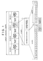
- FIG. 1 shows the basic base band coding structure of RDS data.
- RDS data are formed of groups each having 104 bits. Each group is formed of four blocks (blocks A, B, C and D). Each block is formed of 16-bit information words (m0 to m15), 10-bit check words and offset words (C'0 to C'9). Note that the transmission rate of RDS data is 1187.5 bits per second.
- program identification data program identification code (PI code)
- PI code program identification code
- the PI code is formed of three elements. The three elements are 4-bit country name data, 4-bit area data and 8-bit program data.
- traffic information broadcast station identification data traffic program identification code (TP code)
- TP code traffic program identification code
- TA code traffic announcement identification data
- TA code traffic announcement code
- each group is classified into 16 patterns of types 0 to 15 using 4 bits on the basis of the contents thereof.
- two versions are defined for each type (0 to 15).
- the identification code of the version is arranged in the block B. Note that the type defined as version A definitely contains a PI code in the block A; however, the type defined as version B contains a PI code in the block C in addition to the block A.
- the TMC is broadcast using, for example, eight A groups, that is, eight groups defined as version A, in the RDS data.
- FIG. 2 shows the base band coding structure of eight A groups that transmit the TMC.
- the block A contains a PI code.
- the block B contains not only a 4-bit group type identification code that identifies eight A group types but also various codes relevant to management of a message and an extended system.
- the block B contains a 1-bit short message code "S” that, for example, indicates presence of a short message, a 1-bit group message identification code "G” that indicates whether it is a single group message that one message is transmitted by one group data or a multiple group message that one message is transmitted over multiple data, and a 3-bit traffic jam duration code.
- S 1-bit short message code
- G 1-bit group message identification code
- DP that indicates an approximate traffic jam duration. Note that the traffic jam duration code DP is used to indicate a traffic jam duration (0 to 4 hours) in eight levels.
- the block C for example, contains a detour identification code "D" that indicates the presence or absence of a detour, a 3-bit “EXTENT” code that includes a location offset address, and an 11-bit “EVENT” code that indicates, for example, information, such as weather condition, construction and traffic jam.
- the block D contains 16-bit "LOCATION” code that indicates location information. With the extended system using these codes, various pieces of information, or the like, that appropriately instruct a detour around a traffic jam are transmitted.
- a radio receiver has an automatic tracking function. For example, when a reception level of a broadcast from a currently receiving broadcast station decreases because of disturbance, such as multipath interference, the radio receiver selects a different receivable broadcast station that carries out a different broadcast at the time when the reception level has decreased. The intensity of a radio wave received from the different broadcast station is higher than the intensity of a radio wave received from the currently receiving broadcast station.
- the radio receiver receives RDS-TMC and performs a band scan. Specifically, the radio receiver receives RDS-TMC and performs a band scan in a time-sharing manner.
- the band scan information about a broadcast station in the same group as the currently acquired broadcast station and/or information about a different broadcast station that carries out a broadcast different from that of the currently acquired broadcast station are scanned.
- a PI code scan and a PS code scan are carried out in a full scan, and a broadcast station list is updated.
- information for retrieving or acquiring information about broadcast stations used to display an FM station list screen or an RDS-TMC station list screen is scanned.
- the broadcast stations used to display the RDS-TMC station list screen are broadcast stations that transmit RDS data and broadcast stations that broadcast TMC.
- RDS data are transmitted from each broadcast station, so it is necessary to acquire frequency information in order to tune a tuner to the broadcast station.
- TMC in order to receive TMC, it is necessary to acquire frequency information about broadcast stations that broadcast TMC.
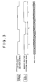
- FIG. 3 shows an example of a time chart that shows an update of a broadcast station list in the radio receiver.
- the time chart shown in FIG. 3 shows switching between a broadcast station list that includes broadcast stations to which the broadcast station may be switched through user's operation and a display screen (another screen) other than the broadcast station list and switching between an RDS-TMC reception executed by the RDS-TMC tuner and a band scan.
- FIG. 3 shows transmission of TMC data. TMC data are transmitted from a predetermined broadcast station. According to FIG. 3 , irrespective of user's operation and transmission time (interval) of TMC data, the RDS-TMC tuner continues given operation.
- the RDS-TMC tuner receives RDS-TMC during an RDS-TMC reception time t 1 , and performs a band scan during a band scan time t 2 after the RDS-TMC reception time t 1 .
- the RDS-TMC reception time t 1 is a time during which RDS-TMC is received.
- RDS reception and TMC reception are carried out.
- surrounding traffic information is acquired.
- the band scan time t 2 is a time during which a PI code and/or a PS code are received.
- the band scan time t 2 depends on the number of broadcast stations located around the radio receiver.
- a band scan is carried out every t 1 +t 2 irrespective of user's operation.
- an interval at which a band scan is carried out is t 1 +t 2 .
- broadcast stations included in the broadcast station list have been acquired t 1 +t 2 before if it is the oldest.
- the invention provides a radio receiver and a method used in a radio receiver that are able to change the timing at which a broadcast station list is updated.
- a first aspect of the invention relates to a radio receiver that receives broadcast station information provided by a radio data system.
- the radio receiver includes: a displayed content information acquisition unit that acquires information indicating displayed contents of a display device; a displayed content determination unit that determines whether the displayed contents of the display device, acquired by the displayed content information acquisition unit, correspond to predetermined displayed contents; a broadcast station information reception time setting unit that sets a time and/or interval at which the broadcast station information is received; and a broadcast station information reception unit that receives the broadcast station information in accordance with the time and/or interval set by the broadcast station information reception time setting unit, wherein the broadcast station information reception time setting unit carries out at least one of reducing the interval at which the broadcast station information is received and extending the time during which the broadcast station information is received when the displayed content determination unit determines that the displayed contents of the display device correspond to the predetermined displayed contents.
- a second aspect of the invention relates to a radio receiver that receives broadcast station information provided by a radio data system.
- the radio receiver includes: a radio broadcast output determination unit that determines whether the radio receiver is outputting a radio broadcast; a broadcast station information reception time setting unit that sets a time and/or interval at which the broadcast station information is received; and a broadcast station information reception unit that receives the broadcast station information in accordance with the time and/or interval set by the broadcast station information reception time setting unit, wherein the broadcast station information reception time setting unit carries out at least one of reducing the interval at which the broadcast station information is received and extending the time during which the broadcast station information is received when the radio broadcast output determination unit determines that the radio broadcast is being output.
- a third aspect of the invention relates to a method used in a radio receiver that receives broadcast station information provided by a radio data system.
- the method includes: acquiring information indicating displayed contents of a display device; determining whether the acquired displayed contents of the display device correspond to predetermined displayed contents; setting a time and/or interval at which the broadcast station information is received; and receiving the broadcast station information in accordance with the set time and/or interval, wherein, when it is determined that the displayed contents of the display device correspond to the predetermined displayed contents, the time and/or interval at which the broadcast station information is received is set by at least one of reducing the interval at which the broadcast station information is received and extending the time during which the broadcast station information is received.
- a fourth aspect of the invention relates to a method used in a radio receiver that receives broadcast station information provided by a radio data system.
- the method includes: determining whether the radio receiver is outputting a radio broadcast; setting a time and/or interval at which the broadcast station information is received; and receiving the broadcast station information in accordance with the set time and/or interval, wherein, when it is determined that the radio broadcast is being output, the time and/or interval at which the broadcast station information is received is set by at least one of reducing the interval at which the broadcast station information is received and extending the time during which the broadcast station information is received.
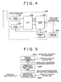
- FIG. 4 shows an example of a system to which a radio receiver according to a first embodiment of the invention is applied.
- the system includes a radio receiver 100 and a display device 200.
- the radio receiver 100 acquires information that indicates contents displayed on the display device 200 (hereinafter, referred to as "displayed content information") from the display device 200.
- the radio receiver 100 determines whether the displayed content information corresponds to predetermined displayed information on the basis of the displayed content information input from the display device 200.
- the radio receiver 100 changes an interval at which a band scan is performed and/or a time during which a band scan is performed.
- the predetermined information includes displayed contents relevant to a radio broadcast, specifically, a broadcast station list.
- the radio receiver 100 reduces the interval at which a band scan is performed and/or extends the time during which a band scan is performed.
- the fact that a broadcast station list is displayed on the display device 200 means that a user is presumably referring to the broadcast station list.
- the interval at which a band scan is performed is reduced and/or the time during which a band scan is performed is extended to make it possible to early acquire the latest broadcast station list. Because the latest broadcast station list may be acquired early, it is possible to increase the probability that the broadcast station list displayed on the display device 200 reflects an actual situation.
- the display device 200 may be included in a navigation system.
- the display device 200 may be included in a system that is a combination of a navigation system and an audio. More generally, the display device 200 may be included in an in-vehicle device.
- the radio receiver 100 dynamically changes the band scan interval in response to the display screen of the display device 200.
- the radio receiver 100 includes a main tuner 102, a sub-tuner 104, a digital signal processor (DSP) 106, an audio central processing unit (CPU) 108 and a storage unit 110.
- DSP digital signal processor
- CPU audio central processing unit
- the main tuner 102 receives a radio broadcast via an antenna.
- the main tuner 102 inputs a received audio signal to the DSP 106.
- the main tuner 102 receives an AM radio broadcast or an FM radio broadcast.
- the sub-tuner 104 includes an RDS-TMC tuner.
- the sub-tuner 104 receives RDS-TMC via an antenna.
- the sub-tuner 104 performs a band scan.
- the sub-tuner 104 scans the situation of another frequency at an alternative frequency. This is because the same program or a different program may be broadcast at different frequencies in the same or adjacent area.
- the band scan information about a broadcast station in the same group and/or different group from a currently acquired broadcast station is scanned.
- information for retrieving or acquiring information about broadcast stations for displaying an FM station list screen or an RDS-TMC station list screen are scanned.
- the sub-tuner 104 inputs a composite signal that includes the RDS-TMC to the DSP 106 and the navigation system (not shown).
- the RDS data contain character information, such as a PI code and a PS code
- the TMC contains traffic information.
- the sub-tuner 104 may be configured to receive a radio broadcast via an antenna together with the main tuner 102.
- the sub-tuner 104 inputs a received audio signal to the DSP 106.
- the sub-tuner 104 switches among receiving a radio broadcast, receiving RDS-TMC and performing a band scan.
- the radio receiver 100 may have an exclusive tuner that receives RDS-TMC in addition to the main tuner 102 and the sub-tuner 104.
- the sub-tuner 104 may be configured to receive only a radio broadcast.
- the DSP 106 is connected to the main tuner 102 and the sub-tuner 104.
- the DSP 106 is controlled by an audio CPU 108 to convert the audio signal input from the main tuner 102 and the sub-tuner 104 into audio and then outputs the audio to a speaker (not shown).
- the DSP 106 performs digital signal processing on the audio signal input from the main tuner 102.
- the DSP 106 performs digital signal processing on the audio signal input from the sub-tuner 104.
- the DSP 106 may synthesize the audio signal input from the main tuner 102 with the audio signal input from the sub-tuner 104 to continue an optimal reception state. For example, a radio broadcast input through the main tuner 102 is synthesized with a radio broadcast input through the sub-tuner 104. By synthesizing audio signals received by the plurality of tuners, it is possible to obtain phase diversity effect.
- the DSP 106 acquires RDS data and/or TMC from the composite signal input from the sub-tuner 104 and then inputs the RDS data and/or TMC to the audio CPU 108.
- the DSP 106 inputs information about another frequency broadcasting the same program in the same or adjacent area (hereinafter, referred to as alternative frequency information), input from the sub-tuner 104, to the audio CPU 108.
- the audio CPU 108 is connected to the sub-tuner 104 and the DSP 106.
- the displayed content information is input from the display device 200 to the audio CPU 108.
- the displayed content information is input to the audio CPU 108 via a predetermined interface.
- the audio CPU 108 determines whether the displayed content information corresponds to predetermined displayed contents on the basis of the displayed content information input from the display device 200.
- the audio CPU 108 changes the interval at which a band scan is performed and/or the time during which a band scan is performed.
- the predetermined displayed contents include displayed contents relevant to a radio broadcast, specifically, a broadcast station list.
- the audio CPU 108 reduces the interval at which a band scan is performed and/or extends the time during which a band scan is performed.
- the latest broadcast station list may be early acquired by reducing the interval at which a band scan is performed and/or extending the time during which a band scan is performed, so it is possible to improve consistency between the currently receivable broadcast stations and the broadcast station list displayed on the display device 200.
- the storage unit 110 is connected to the audio CPU 108.
- the storage unit 110 stores an application and an operating system (OS).
- the application is software that has a function of executing operation that is executed on the radio receiver 100 by the user.
- the operating system is software that provides the application with an interface that abstracts hardware in the radio receiver 100.
- the audio CPU 108 functions in accordance with a program stored in the storage unit 110, and carries out predetermined processing.
- FIG. 5 is a functional block diagram that shows the functions of the radio receiver 100.
- FIG. 5 mainly shows the functions of the audio CPU 108.
- the audio CPU 108 includes a display screen determination unit 1082, a band scan processing time setting unit 1084 and a band scan processing control unit 1086.
- the displayed content information is input from the display device 200 to the display screen determination unit 1082.
- the display screen determination unit 1082 determines whether the displayed content information corresponds to predetermined displayed contents on the basis of the displayed content information.
- the predetermined displayed contents include displayed contents relevant to a radio broadcast. For example, a broadcast station list is included in the predetermined displayed contents.
- the display screen determination unit 1082 inputs the result of determination, as to whether the displayed content information corresponds to the predetermined displayed contents, to the band scan processing time setting unit 1084.
- the result of determination as to whether the displayed content information corresponds to the predetermined displayed contents is referred to as "displayed contents determination result".
- the band scan processing time setting unit 1084 is connected to the display screen determination unit 1082.
- the band scan processing time setting unit 1084 changes the interval at which a band scan is performed and/or the time during which a band scan is performed. For example, when the displayed contents determination result indicates that the displayed content information corresponds to the displayed contents relevant to a radio broadcast, the band scan processing time setting unit 1084 reduces the interval at which a band scan is performed and/or extends the time during which a band scan is performed.
- the radio receiver 100 is presumably performing operation other than receiving a radio broadcast.
- the radio receiver 100 is carrying out operation other than receiving a radio broadcast, it is desirable that the operation other than receiving a radio broadcast is continued.
- the operation other than receiving a radio broadcast includes receiving traffic information.
- traffic information is being received, a navigation screen is presumably displayed on the display device 200.
- the navigation screen includes map information.
- the navigation screen is not displayed, even when the priority of receiving the traffic information is lowered, the influence arising from the lowered priority of receiving traffic information is presumably small.
- the radio receiver 100 reduces the interval at which a band scan is performed and/or extends the time during which a band scan is performed. In other words, the radio receiver 100 executes control such that the priority of performing a band scan is raised and the priority of receiving traffic information is lowered.
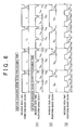
- FIG. 6 is a time chart that shows an example of changing a band scan processing time.
- an RDS-TMC reception time T 1 and a band scan time T 2 come in a time-sharing manner.
- the RDS-TMC reception time is T 1
- the band scan time is T 2 .
- a time obtained from the sum of the RDS-TMC reception time T 1 and the band scan time T 2 may be termed a band scan interval.
- the band scan interval (T 1 +T 2 ) may be A minutes
- the band scan time T 2 may be B minutes (A > B).
- the band scan processing time setting unit 1084 changes the interval at which a band scan is performed. For example, when the displayed contents determination result indicates that the displayed content information corresponds to the displayed contents relevant to a radio broadcast, the band scan processing time setting unit 1084 reduces the interval at which a band scan is performed.
- FIG. 6 (1) shows the case where the band scan interval is halved as an example. The band scan interval may be reduced to one-third or may be reduced to three-fourths. When the band scan interval is halved, the RDS-TMC reception time and the band scan time are also halved.
- the band scan interval (T 1 +T 2 ) before changing the band scan processing time is A minutes and the band scan time T 2 is B minutes (A > B)
- Ta 1 is equal to (A-B)/2
- Ta 2 is equal to B/2.
- the interval at which the broadcast station list is updated is reduced by reducing the interval at which a band scan is performed, so the freshness of information about currently receivable broadcast stations (station list) may be improved. In other words, information about the currently receivable broadcast stations (station list) may be kept fresh.
- the band scan processing time setting unit 1084 changes the time during which a band scan is performed. For example, when the displayed contents determination result indicates that the displayed content information corresponds to the displayed contents relevant to a radio broadcast, the band scan processing time setting unit 1084 does not change the interval at which a band scan is performed but extends the time during which a band scan is performed.
- FIG. 6 (2) shows the case where the band scan interval is not changed but the time during which a band scan is performed is doubled as an example. Note that the time during which a band scan is performed may be extended by half or may be tripled.
- the time during which a band scan is performed may be extended. For example, when the band scan interval (T 1 +T 2 ) before changing the band scan processing time is A minutes and the band scan time T 2 is B minutes, and when the band scan time is doubled, Tb 1 is equal to (A-2B) and Tb 2 is equal to 2B.
- Tb 1 is equal to (A-2B) and Tb 2 is equal to 2B.
- the band scan processing time setting unit 1084 changes the interval at which a band scan is performed and the time during which a band scan is performed. For example, when the displayed contents determination result indicates that the displayed content information corresponds to the displayed contents relevant to a radio broadcast, the band scan processing time setting unit 1084 reduces the interval at which a band scan is performed and extends the time during which a band scan is performed.
- FIG. 6 (3) shows the case where the band scan interval is halved and the time during which a band scan is performed is doubled as an example. The band scan interval may be reduced to one-third or may be reduced to three-fourths.
- the time during which a band scan is performed may be extended by half or may be tripled. Within the allowable range of the influence on the TMC received in the RDS-TMC reception time, the time during which a band scan is performed may be extended. For example, when the band scan interval (T 1 +T 2 ) before changing the band scan processing time is A minutes and the band scan time T 2 is B minutes (A > B), and when the band scan interval is halved and the time during which a band scan is performed is doubled, Tc 1 is equal to (A-4B)/2 and Tc 2 is equal to 2B.
- the interval at which the broadcast station list is updated is reduced by reducing the interval at which a band scan is performed and further by extending the time during which a band scan is performed, so the freshness of information about currently receivable broadcast stations (station list) may be improved, and the quality of information about currently receivable broadcast stations (station list) may be improved.
- the time during which a band scan is performed is changed.
- An element that influences the time during which a band scan is performed may be the number of broadcast stations. This is because a band scan takes time or ends in a short period of time depending on the number of broadcast stations arranged in each area. When the number of broadcast stations is small, frequency is skipped, so the band scan processing time reduces. Thus, when the number of broadcast stations arranged in each area is known, the band scan time may be increased or decreased depending on the number of broadcast stations. In other words, when the number of broadcast stations arranged in each area is known, broadcast stations to be scanned may be narrowed.
- an element that influences the time during which a band scan is performed may be reception quality.
- Whether to incorporate a broadcast station into the broadcast station list is determined on the basis of whether the reception quality of a signal transmitted from the broadcast station satisfies predetermined reception quality.
- the set predetermined reception quality is high, the number of broadcast stations that satisfy the predetermined reception quality reduces, so the band scan processing time reduces.
- the set predetermined reception quality is low, the number of broadcast stations that satisfy the predetermined reception quality increases, so the processing time extends.
- the band scan time is set to a time during which broadcast stations that satisfy the predetermined reception quality may be sufficiently scanned.
- the band scan processing time setting unit 1084 inputs band scan processing time setting information to the band scan processing control unit 1086.
- the band scan processing time setting information may include a band scan interval and a band scan time:
- the band scan processing time setting information may include an RDS-TMC reception time and a band scan time.
- the band scan processing time setting information may include a band scan interval and an RDS-TMC reception time.
- the band scan processing time setting information may include a band scan interval, an RDS-TMC reception time and a band scan interval. The information included in the band scan processing time setting information may be appropriately changed.
- the band scan processing control unit 1086 is connected to the band scan processing time setting unit 1084.
- the band scan processing control unit 1086 controls the RDS-TMC reception time and the band scan time in accordance with the band scan processing time setting information input from the band scan processing time setting unit 1084. Specifically, the band scan processing control unit 1086 controls the RDS-TMC reception time and band scan time of the sub-tuner 104.
- the sub-tuner 104 is controlled by the band scan processing control unit 1086 to perform a full scan. In the full scan, a PI code and a PS code are scanned.
- the band scan processing control unit 1086 acquires information about broadcast stations that satisfy predetermined reception quality from the sub-tuner 104.
- the band scan processing control unit 1086 incorporates the broadcast stations, acquired from the sub-tuner 104, into the broadcast station list.
- the broadcast station list shows broadcast stations in order of high reception quality.
- the band scan processing control unit 1086 interchanges the order of the broadcast stations included in the broadcast station list on the basis of the reception quality. Even when the band scan time terminates in process of a band scan made by the sub-tuner 104, broadcast stations acquired during the band scan time may be incorporated into the broadcast station list.
- FIG. 7 is a flowchart that shows the operation of the radio receiver 100.
- the flowchart shown in FIG. 7 shows an example in which, when the displayed contents of the display device 200 correspond to the broadcast station list, the interval at which a band scan is performed and the time during which a band scan is performed are changed in accordance with the third example of changing the band scan processing time, described with reference to FIG. 6 .
- the operation of the radio receiver 100 also applies to the case where the first example of changing the band scan processing time is applied and the case where the second example of changing the band scan processing time is applied.
- the radio receiver 100 determines whether a screen displayed on the display device 200 is a broadcast station list (step S702). For example, the display screen determination unit 1082 acquires the displayed content information from the display device 200. The display screen determination unit 1082 determines whether the displayed content information is information that indicates the broadcast station list. The display screen determination unit 1082 inputs the displayed contents determination result to the band scan processing time setting unit 1084.
- the radio receiver 100 sets the band scan time to Tc 2 and sets the band scan interval to Tc 1 +Tc 2 (step S704).
- the band scan processing time setting unit 1084 changes the interval at which a band scan is performed and the time during which a band scan is performed because the result of determination indicated by the displayed contents determination result indicates that the displayed content information is the broadcast station list according to the displayed contents determination result input from the display screen determination unit 1082.
- the band scan processing time setting unit 1084 sets the band scan time to Tc 2 and sets the band scan interval to Tc 1 +Tc 2 .
- the band scan processing time setting unit 1084 inputs the band scan processing time setting information, including the band scan time and the band scan interval, to the band scan processing control unit 1086.
- the information included in the band scan processing time setting information is an example, and may be appropriately changed as described above.
- the radio receiver 100 sets the band scan time to T 2 and sets the band scan interval to T 1 +T 2 (step S706).
- the band scan processing time setting unit 1084 sets the band scan time to T 2 and sets the band scan interval to T 1 +T 2 because the result of determination indicated by the displayed contents determination result does not indicate that the displayed content information is the broadcast station list according to the displayed contents determination result input from the display screen determination unit 1082.
- the band scan processing time setting unit 1084 inputs the band scan processing time setting information, including the band scan time and the band scan interval, to the band scan processing control unit 1086.
- the information included in the band scan processing time setting information is an example, and may be appropriately changed as described above.
- the radio receiver 100 starts a band scan interval timer (step S708).
- the band scan processing control unit 1086 sets the band scan interval for the band scan interval timer in accordance with the band scan processing time setting information input from the band scan processing time setting unit 1084 and then starts the band scan interval timer.
- the radio receiver 100 determines whether the interval timer times out (step S710). For example, the band scan processing control unit 1086 determines whether the band scan interval timer set in step S708 times out (step S710).
- the radio receiver 100 performs a band scan (step S712).
- the band scan processing control unit 1086 determines that the band scan interval timer times out
- the band scan processing control unit 1086 controls the sub-tuner 104 to perform a band scan.
- the sub-tuner 104 is controlled by the band scan processing control unit 1086 to perform a full scan. In the full scan, a PI code and a PS code are scanned.
- the band scan processing control unit 1086 acquires information about broadcast stations that satisfy predetermined reception quality from the sub-tuner 104.
- the band scan processing control unit 1086 incorporates the broadcast stations, acquired from the sub-tuner 104, into the broadcast station list.
- the broadcast station list shows broadcast stations in order of high reception quality.
- the band scan processing control unit 1086 interchanges the order of the broadcast stations included in the broadcast station list on the basis of the reception quality. Even when the band scan time terminates in process of a band scan made by the sub-tuner 104, broadcast stations acquired during the band scan time may be incorporated into the broadcast station list.
- the band scan time may be set to T 2 , and the band scan interval may be set to T 1 +T 2 .
- the band scan time is set to T 2
- the band scan interval is set to T 1 +T 2 .
- the band scan interval may be changed to a corresponding band scan interval.
- steps S702 to S712 are executed in such a manner that the audio CPU 108 mounted on the radio receiver 100 carries out processing in accordance with a program.
- the program for causing the audio CPU 108 to function as the radio receiver 100 is, for example, downloaded through a network.
- the above program may be provided in a state of being recorded in a recording medium, such as a flexible disk, a CD-ROM and a memory card.
- the program is provided through a recording medium, as the recording medium is inserted into an auxiliary storage device connected to the radio receiver 100, the program recorded in the recording medium is loaded.
- the audio CPU 108 writes the loaded program into a RAM or an HDD, and then executes processing.
- the program causes the computer (audio CPU 108) of the radio receiver 100 to execute steps S702 to S712 in FIG. 7 .
- the program may be configured to execute at least part of steps.
- the reception interval (update interval) of the broadcast station list is changed on the basis of the type of screen currently displayed on the display device. Specifically, when the currently displayed screen is the broadcast station list, the reception interval (update interval) of the broadcast station list is reduced. By reducing the update interval of the broadcast station list while the broadcast station list is being displayed, the freshness of information about the currently receivable broadcast stations (station list) may be improved. In addition, by extending the time during which a band scan is performed, the quality of information about currently receivable broadcast stations (station list) may be improved. In addition, although influenced by display timing as well, it is possible to improve consistency between the currently receivable broadcast stations and the broadcast station list displayed on the display device.
- radio broadcast output information Information that indicates whether the radio receiver 100 is outputting a radio broadcast (hereinafter, referred to as "radio broadcast output information”) is input to the audio CPU 108.
- the audio CPU 108 determines whether the radio broadcast output information indicates that a radio broadcast is being output on the basis of the radio broadcast output information.
- the audio CPU 108 changes the interval at which a band scan is performed and/or the time during which a band scan is performed.
- the audio CPU 108 reduces the interval at which a band scan is performed and/or extends the time during which a band scan is performed.
- the fact that a radio broadcast is being output means that the user is presumably referring to the broadcast station list.
- the interval at which a band scan is performed is reduced and/or the time during which a band scan is performed is extended to make it possible to early acquire the latest broadcast station list. Because the latest broadcast station list may be acquired early, it is possible to increase the probability that the broadcast station list displayed on the display device 200 reflects a current situation.
- FIG. 8 is a functional block diagram that shows the functions of the radio receiver 100.
- FIG. 8 mainly describes the functions of the audio CPU 108.
- the radio broadcast output information is input to the radio broadcast output determination unit 1088.
- the radio broadcast output determination unit 1088 determines whether the radio broadcast output information indicates that a radio broadcast is being output on the basis of the radio broadcast output information.
- the radio broadcast output determination unit 1088 inputs the result of determination, as to whether the radio broadcast output information indicates that a radio broadcast is being output, to the band scan processing time setting unit 1084.
- the result of determination, as to whether the radio broadcast output information indicates that a radio broadcast is being output is referred to as "radio broadcast output determination result”.
- the band scan processing time setting unit 1084 is connected to the radio broadcast output determination unit 1088.
- the band scan processing time setting unit 1084 changes the interval at which a band scan is performed and/or the time during which a band scan is performed. For example, when the radio broadcast output determination result indicates that a radio broadcast is being output, the band scan processing time setting unit 1084 reduces the interval at which a band scan is performed and/or extends the time during which a band scan is performed.
- the radio receiver 100 is presumably performing operation other than receiving a radio broadcast.
- the radio receiver 100 is performing operation other than receiving a radio broadcast, it is desirable that the operation is continued.
- the operation other than receiving a radio broadcast includes receiving traffic information.
- traffic information is being received, a navigation screen is presumably displayed on the display device 200.
- the navigation screen includes map information.
- the navigation screen is not displayed, even when the priority of receiving the traffic information is lowered, the influence arising from the lowered priority of receiving traffic information is presumably small.
- the radio receiver 100 reduces the interval at which a band scan is performed and/or extends the time during which a band scan is performed. In other words, control for lowering the priority of receiving traffic information is executed.
- FIG. 9 is a flowchart that shows the operation of the radio receives 100.
- the flowchart shown in FIG. 9 shows an example in which, when a radio broadcast is being output, the interval at which a band scan is performed and the time during which a band scan is performed are changed in accordance with the third example of changing the band scan processing time, described with reference to FIG. 6 .
- the operation of the radio receiver 100 also applies to the case where the first example of changing the band scan processing time is applied and the case where the second example of changing the band scan processing time is applied.
- the radio receiver 100 determines whether a radio broadcast is being output (step S902). For example, the radio broadcast output determination unit 1088 acquires the radio broadcast output information. The radio broadcast output determination unit 1088 determines whether the radio broadcast output information indicates that a radio broadcast is being output. The radio broadcast output determination unit 1088 inputs the radio broadcast output determination result to the band scan processing time setting unit 1084.
- the radio receiver 100 sets the band scan time to Tc 2 and sets the band scan interval to Tc 1 +Tc 2 (step S904).
- the band scan processing time setting unit 1084 changes the interval at which a band scan is performed and the time during which a band scan is performed because the result of determination indicated by the radio broadcast output determination result indicates that a radio broadcast is being output according to the radio broadcast output determination result input from the radio broadcast output determination unit 1088.
- the band scan processing time setting unit 1084 sets the band scan time to Tc 2 and sets the band scan interval to Tc 1 +Tc 2 .
- the band scan processing time setting unit 1084 inputs the band scan processing time setting information, including the band scan time and the band scan interval, to the band scan processing control unit 1086.
- the information included in the band scan processing time setting information is an example, and may be appropriately changed as described above.
- the radio receiver 100 sets the band scan time to T 2 and sets the band scan interval to T 1 +T 2 (step S906).
- the band scan processing time setting unit 1084 sets the band scan time to T 2 and sets the band scan interval to T 1 +T 2 because the result of determination indicated by the radio broadcast output determination result does not indicate that a radio broadcast is being output according to the radio broadcast output determination result input from the radio broadcast output determination unit 1088.
- the band scan processing time setting unit 1084 inputs the band scan processing time setting information, including the band scan time and the band scan interval, to the band scan processing control unit 1086.
- the information included in the band scan processing time setting information is an example, and may be appropriately changed as described above.
- steps S908 to S912 is similar to that of steps S708 to S712 described with reference to FIG. 7 .
- the band scan time may be set to T 2 , and the band scan interval may be set to T 1 +T 2 .
- the band scan time is set to T 2
- the band scan interval is set to T 1 +T 2 .
- the band scan interval may be changed to a corresponding band scan interval.
- steps S902 to S912 are executed in such a manner that the audio CPU 108 mounted on the radio receiver 100 carries out processing in accordance with a program.
- the program for causing the audio CPU 108 to function as the radio receiver 100 is, for example, downloaded through a network.
- the above program may be provided in a state of being recorded in a recording medium, such as a flexible disk, a CD-ROM and a memory card.
- the program is provided through a recording medium, as the recording medium is inserted into an auxiliary storage device connected to the radio receiver 100, the program recorded in the recording medium is loaded.
- the audio CPU 108 writes the loaded program into a RAM or an HDD, and then executes processing.
- the program causes the computer (audio CPU 108) of the radio receiver 100 to execute steps S902 to S912 in FIG. 9 .
- the program may be configured to execute at least part of steps.
- the reception interval (update interval) of the broadcast station list is changed on the basis of whether a radio broadcast is being output. Specifically, when a radio broadcast is being output, the reception interval (update interval) of the broadcast station list is reduced. By reducing the update interval of the broadcast station list while a radio broadcast is being output, the freshness of information about the currently receivable broadcast stations (station list) may be improved. In addition, by extending the time during which a band scan is performed, the quality of information about currently receivable broadcast stations (station list) may be improved. In addition, although influenced by display timing as well, it is possible to improve consistency between the currently receivable broadcast stations and the broadcast station list displayed on the display device.
- a radio receiver is provided.
- the radio receiver that receives broadcast station information provided by a radio data system includes: a displayed content information acquisition unit that serves as a display screen determination unit and that acquires information indicating displayed contents of a display device; a displayed content determination unit that serves as a display screen determination unit and that determines whether the displayed contents of the display device, acquired by the displayed content information, correspond to predetermined displayed contents; a broadcast station information reception time setting unit that serves as a band scan processing time setting unit and that sets a time and/or interval at which the broadcast station information is received; and a broadcast station information reception unit that serves as a band scan processing control unit and that receives the broadcast station information in accordance with the time and/or interval set by the broadcast station information reception time setting unit, wherein the broadcast station information reception time setting unit reduces the interval at which the broadcast station information is received when the displayed content determination unit determines that the displayed contents of the display device correspond to the predetermined displayed contents.
- the interval at which the broadcast station information is received is reduced to make it possible to early acquire the latest broadcast station information.
- the predetermined displayed contents are desirably displayed contents relevant to a radio broadcast. Because the latest broadcast station information may be acquired early, it is possible to increase the probability that the broadcast station information displayed on the display device reflects an actual situation.
- the broadcast station information reception time setting unit extends the time during which the broadcast station information is received when the displayed content determination unit determines that the displayed contents of the display device correspond to the predetermined displayed contents.
- the time during which the broadcast station information is received is extended to make it possible to early acquire the latest broadcast station information.
- the predetermined displayed contents are desirably displayed contents relevant to a radio broadcast. Because the latest broadcast station information may be acquired early, it is possible to increase the probability that the broadcast station information displayed on the display device reflects an actual situation.
- the predetermined displayed contents include a screen of a broadcast station list.
- the predetermined displayed contents are the broadcast station list, it is possible to increase the probability that the broadcast station list displayed on the display device reflects an actual situation.
- the radio receiver that receives broadcast station information provided by a radio data system includes: a radio broadcast output determination unit that serves as a radio broadcast output determination unit and that determines whether a radio broadcast is being output; a broadcast station information reception time setting unit that serves as a band scan processing time setting unit and that sets a time and/or interval at which the broadcast station information is received; and a broadcast station information reception unit that serves as a band scan processing control unit and that receives the broadcast station information in accordance with the time and/or interval set by the broadcast station information reception time setting unit, wherein the broadcast station information reception time setting unit reduces the interval at which the broadcast station information is received when the radio broadcast output determination unit determines that the radio broadcast is being output.
- the interval at which the broadcast station information is received is reduced to make it possible to early acquire the latest broadcast station information. Because the latest broadcast station information may be acquired early, it is possible to increase the probability that the broadcast station information displayed on the display device reflects an actual situation.
- the broadcast station information reception time setting unit extends the time during which the broadcast station information is received when the radio broadcast output determination unit determines that the radio broadcast is being output.
- the time during which the broadcast station information is received is extended to make it possible to early acquire the latest broadcast station information. Because the latest broadcast station information may be acquired early, it is possible to increase the probability that the broadcast station information displayed on the display device reflects an actual situation.
- the radio receiver is mostly applied to an in-vehicle tuner intended for Europe. Even in an area other than Europe, such as Japan and the United States, the radio receiver may be applied in an area in which a similar application is used. For example, in each area, the radio receiver may be applied when similar information about a broadcast station is updated.
Landscapes
- Engineering & Computer Science (AREA)
- Signal Processing (AREA)
- Circuits Of Receivers In General (AREA)
Abstract
Description
- The invention relates to a radio receiver.
- In Europe, the widespread use of radio data system-traffic message channel (RDS-TMC) that provides traffic information using FM broadcasting has been promoted.
- The RDS is a digital data multiplexing system developed under the leadership of Europe that mainly uses FM broadcasting as a radio broadcasting service and standardized by European Broadcasting Union (EBU).
- The RDS is particularly effective mainly in areas in which a large number of networked broadcast stations broadcast the same program. Specifically, 57 kHz that is a third-order harmonic of 19-kHz stereo pilot signal is used as a subcarrier. Then, a data signal that indicates filtered and binary-phase coded data, such as program relevant information and traffic relevant information, is used to modulate the subcarrier in amplitude to generate a radio data signal. Then, the amplitude-modulated subcarrier is modulated in frequency into a main carrier for broadcasting. The radio data signal is called RDS data.
-
FIG. 1 shows the basic base band coding structure of RDS data. - RDS data are formed of groups each having 104 bits. Each group is formed of four blocks (blocks A, B, C and D). Each block is formed of 16-bit information words (m0 to m15), 10-bit check words and offset words (C'0 to C'9). Note that the transmission rate of RDS data is 1187.5 bits per second.
- In the block A, program identification data (program identification code (PI code)) that indicates a network formed of country name data and program data are arranged. The PI code is formed of three elements. The three elements are 4-bit country name data, 4-bit area data and 8-bit program data. In the block B, traffic information broadcast station identification data (traffic program identification code (TP code)) that indicates that a broadcast station is a traffic information broadcast station that broadcasts a traffic information program and traffic announcement identification data (traffic announcement code (TA code)) that indicates a start of a broadcast program relevant to traffic information are arranged. In the block C, data relevant to the frequency of each of broadcast stations of a broadcast station group that is broadcasting the same program are arranged. In other words, in the block C, alternative station frequency data (alternative frequency code (AF code)) are arranged. In the block D, broadcast station name data (program service code (PS code)), such as broadcast station name and network name, are arranged.
- In addition, each group is classified into 16 patterns of types 0 to 15 using 4 bits on the basis of the contents thereof. Furthermore, two versions (A and B) are defined for each type (0 to 15). The identification code of the version is arranged in the block B. Note that the type defined as version A definitely contains a PI code in the block A; however, the type defined as version B contains a PI code in the block C in addition to the block A.
- The TMC is broadcast using, for example, eight A groups, that is, eight groups defined as version A, in the RDS data.
-
FIG. 2 shows the base band coding structure of eight A groups that transmit the TMC. - The block A contains a PI code. The block B contains not only a 4-bit group type identification code that identifies eight A group types but also various codes relevant to management of a message and an extended system. The block B contains a 1-bit short message code "S" that, for example, indicates presence of a short message, a 1-bit group message identification code "G" that indicates whether it is a single group message that one message is transmitted by one group data or a multiple group message that one message is transmitted over multiple data, and a 3-bit traffic jam duration code. "DP" that indicates an approximate traffic jam duration. Note that the traffic jam duration code DP is used to indicate a traffic jam duration (0 to 4 hours) in eight levels.
- The block C, for example, contains a detour identification code "D" that indicates the presence or absence of a detour, a 3-bit "EXTENT" code that includes a location offset address, and an 11-bit "EVENT" code that indicates, for example, information, such as weather condition, construction and traffic jam. The block D, contains 16-bit "LOCATION" code that indicates location information. With the extended system using these codes, various pieces of information, or the like, that appropriately instruct a detour around a traffic jam are transmitted.
- A radio receiver has an automatic tracking function. For example, when a reception level of a broadcast from a currently receiving broadcast station decreases because of disturbance, such as multipath interference, the radio receiver selects a different receivable broadcast station that carries out a different broadcast at the time when the reception level has decreased. The intensity of a radio wave received from the different broadcast station is higher than the intensity of a radio wave received from the currently receiving broadcast station.
- The radio receiver receives RDS-TMC and performs a band scan. Specifically, the radio receiver receives RDS-TMC and performs a band scan in a time-sharing manner. In the band scan, information about a broadcast station in the same group as the currently acquired broadcast station and/or information about a different broadcast station that carries out a broadcast different from that of the currently acquired broadcast station are scanned. Specifically, in the band scan, a PI code scan and a PS code scan are carried out in a full scan, and a broadcast station list is updated. In the band scan, information for retrieving or acquiring information about broadcast stations used to display an FM station list screen or an RDS-TMC station list screen is scanned. The broadcast stations used to display the RDS-TMC station list screen are broadcast stations that transmit RDS data and broadcast stations that broadcast TMC. For example, RDS data are transmitted from each broadcast station, so it is necessary to acquire frequency information in order to tune a tuner to the broadcast station. In addition, in order to receive TMC, it is necessary to acquire frequency information about broadcast stations that broadcast TMC.
-
FIG. 3 shows an example of a time chart that shows an update of a broadcast station list in the radio receiver. The time chart shown inFIG. 3 shows switching between a broadcast station list that includes broadcast stations to which the broadcast station may be switched through user's operation and a display screen (another screen) other than the broadcast station list and switching between an RDS-TMC reception executed by the RDS-TMC tuner and a band scan. In addition,FIG. 3 shows transmission of TMC data. TMC data are transmitted from a predetermined broadcast station. According toFIG. 3 , irrespective of user's operation and transmission time (interval) of TMC data, the RDS-TMC tuner continues given operation. - According to
FIG. 3 , the RDS-TMC tuner receives RDS-TMC during an RDS-TMC reception time t1, and performs a band scan during a band scan time t2 after the RDS-TMC reception time t1. The RDS-TMC reception time t1 is a time during which RDS-TMC is received. During the RDS-TMC reception time t1, RDS reception and TMC reception are carried out. During the RDS-TMC reception time t1, surrounding traffic information is acquired. The band scan time t2 is a time during which a PI code and/or a PS code are received. The band scan time t2 depends on the number of broadcast stations located around the radio receiver. - A band scan is carried out every t1+t2 irrespective of user's operation. In other words, an interval at which a band scan is carried out is t1+t2. For example, when the broadcast station list is displayed on the display screen through user's operation, broadcast stations included in the broadcast station list have been acquired t1+t2 before if it is the oldest.
- When a current reception condition changes with respect to a condition in which a band scan is carried out, the following situation may occur. Even when a broadcast station included in the broadcast station list is selected, it is impossible to receive a radio wave from the broadcast station because of deterioration of the reception condition of a radio wave from the broadcast station. In addition, even when a broadcast station included in the broadcast station list is selected, a radio wave from the broadcast station may be received, but a broadcast different from a desired broadcast is received because the broadcast station information is old. This is because broadcast stations included in the broadcast station list do not reflect a current reception condition.
- The invention provides a radio receiver and a method used in a radio receiver that are able to change the timing at which a broadcast station list is updated.
- A first aspect of the invention relates to a radio receiver that receives broadcast station information provided by a radio data system. The radio receiver includes: a displayed content information acquisition unit that acquires information indicating displayed contents of a display device; a displayed content determination unit that determines whether the displayed contents of the display device, acquired by the displayed content information acquisition unit, correspond to predetermined displayed contents; a broadcast station information reception time setting unit that sets a time and/or interval at which the broadcast station information is received; and a broadcast station information reception unit that receives the broadcast station information in accordance with the time and/or interval set by the broadcast station information reception time setting unit, wherein the broadcast station information reception time setting unit carries out at least one of reducing the interval at which the broadcast station information is received and extending the time during which the broadcast station information is received when the displayed content determination unit determines that the displayed contents of the display device correspond to the predetermined displayed contents.
- A second aspect of the invention relates to a radio receiver that receives broadcast station information provided by a radio data system. The radio receiver includes: a radio broadcast output determination unit that determines whether the radio receiver is outputting a radio broadcast; a broadcast station information reception time setting unit that sets a time and/or interval at which the broadcast station information is received; and a broadcast station information reception unit that receives the broadcast station information in accordance with the time and/or interval set by the broadcast station information reception time setting unit, wherein the broadcast station information reception time setting unit carries out at least one of reducing the interval at which the broadcast station information is received and extending the time during which the broadcast station information is received when the radio broadcast output determination unit determines that the radio broadcast is being output.
- A third aspect of the invention relates to a method used in a radio receiver that receives broadcast station information provided by a radio data system. The method includes: acquiring information indicating displayed contents of a display device; determining whether the acquired displayed contents of the display device correspond to predetermined displayed contents; setting a time and/or interval at which the broadcast station information is received; and receiving the broadcast station information in accordance with the set time and/or interval, wherein, when it is determined that the displayed contents of the display device correspond to the predetermined displayed contents, the time and/or interval at which the broadcast station information is received is set by at least one of reducing the interval at which the broadcast station information is received and extending the time during which the broadcast station information is received.
- A fourth aspect of the invention relates to a method used in a radio receiver that receives broadcast station information provided by a radio data system. The method includes: determining whether the radio receiver is outputting a radio broadcast; setting a time and/or interval at which the broadcast station information is received; and receiving the broadcast station information in accordance with the set time and/or interval, wherein, when it is determined that the radio broadcast is being output, the time and/or interval at which the broadcast station information is received is set by at least one of reducing the interval at which the broadcast station information is received and extending the time during which the broadcast station information is received.
- According to the aspects of the invention, it is possible to change the timing at which the broadcast station list is updated.
- The features, advantages, and technical and industrial significance of this invention will be described below with reference to the accompanying drawings, in which like numerals denote like elements, and wherein:
-
FIG. 1 is a view that illustrates an example of the base band coding structure of RDS data; -
FIG. 2 is a view that illustrates an example of the base band coding structure of TMC; -
FIG. 3 is a time chart that shows an example of timing at which a broadcast station list is updated; -
FIG. 4 is a block diagram that shows one example of the configuration of a radio receiver according to a first embodiment of the invention; -
FIG. 5 is a functional block diagram that shows the radio receiver according to the first embodiment of the invention; -
FIG. 6 is a timing chart that shows an example of timing at which the radio receiver according to the first embodiment of the invention receives broadcast station information; -
FIG. 7 is a flowchart that shows an example of operation of the radio receiver according to the first embodiment of the invention; -
FIG. 8 is a functional block diagram that shows a radio receiver according to a second embodiment of the invention; and -
FIG. 9 is a flowchart that shows an example of operation of the radio receiver according to the second embodiment of the invention; - Hereinafter, embodiments of the invention will be described with reference to the accompanying drawings. Note that, in all the drawings for illustrating the embodiments, like reference numerals denote components having the same functions, and the overlap description is omitted.
-
FIG. 4 shows an example of a system to which a radio receiver according to a first embodiment of the invention is applied. - The system includes a
radio receiver 100 and adisplay device 200. - In this system, the
radio receiver 100 acquires information that indicates contents displayed on the display device 200 (hereinafter, referred to as "displayed content information") from thedisplay device 200. Theradio receiver 100 determines whether the displayed content information corresponds to predetermined displayed information on the basis of the displayed content information input from thedisplay device 200. When theradio receiver 100 determines that the displayed content information corresponds to the predetermined displayed information, theradio receiver 100 changes an interval at which a band scan is performed and/or a time during which a band scan is performed. The predetermined information includes displayed contents relevant to a radio broadcast, specifically, a broadcast station list. When the displayed content information corresponds to a broadcast station list, theradio receiver 100 reduces the interval at which a band scan is performed and/or extends the time during which a band scan is performed. The fact that a broadcast station list is displayed on thedisplay device 200 means that a user is presumably referring to the broadcast station list. Thus, when a broadcast station list is displayed on thedisplay device 200, the interval at which a band scan is performed is reduced and/or the time during which a band scan is performed is extended to make it possible to early acquire the latest broadcast station list. Because the latest broadcast station list may be acquired early, it is possible to increase the probability that the broadcast station list displayed on thedisplay device 200 reflects an actual situation. - The
display device 200 may be included in a navigation system. In addition, thedisplay device 200 may be included in a system that is a combination of a navigation system and an audio. More generally, thedisplay device 200 may be included in an in-vehicle device. - The
radio receiver 100 dynamically changes the band scan interval in response to the display screen of thedisplay device 200. - The
radio receiver 100 includes amain tuner 102, a sub-tuner 104, a digital signal processor (DSP) 106, an audio central processing unit (CPU) 108 and astorage unit 110. - The
main tuner 102 receives a radio broadcast via an antenna. Themain tuner 102 inputs a received audio signal to theDSP 106. For example, themain tuner 102 receives an AM radio broadcast or an FM radio broadcast. - The sub-tuner 104 includes an RDS-TMC tuner. The sub-tuner 104 receives RDS-TMC via an antenna. In addition, the sub-tuner 104 performs a band scan. The sub-tuner 104 scans the situation of another frequency at an alternative frequency. This is because the same program or a different program may be broadcast at different frequencies in the same or adjacent area. In the band scan, information about a broadcast station in the same group and/or different group from a currently acquired broadcast station is scanned. In addition, in the band scan, information for retrieving or acquiring information about broadcast stations for displaying an FM station list screen or an RDS-TMC station list screen are scanned. The sub-tuner 104 inputs a composite signal that includes the RDS-TMC to the
DSP 106 and the navigation system (not shown). As described above, the RDS data contain character information, such as a PI code and a PS code, and the TMC contains traffic information. - In addition, the sub-tuner 104 may be configured to receive a radio broadcast via an antenna together with the
main tuner 102. The sub-tuner 104 inputs a received audio signal to theDSP 106. The sub-tuner 104 switches among receiving a radio broadcast, receiving RDS-TMC and performing a band scan. - In addition, the
radio receiver 100 may have an exclusive tuner that receives RDS-TMC in addition to themain tuner 102 and the sub-tuner 104. When theradio receiver 100 has an exclusive tuner that receives RDS-TMC, the sub-tuner 104 may be configured to receive only a radio broadcast. - The
DSP 106 is connected to themain tuner 102 and the sub-tuner 104. TheDSP 106 is controlled by anaudio CPU 108 to convert the audio signal input from themain tuner 102 and the sub-tuner 104 into audio and then outputs the audio to a speaker (not shown). TheDSP 106 performs digital signal processing on the audio signal input from themain tuner 102. In addition, theDSP 106 performs digital signal processing on the audio signal input from the sub-tuner 104. In addition, theDSP 106 may synthesize the audio signal input from themain tuner 102 with the audio signal input from the sub-tuner 104 to continue an optimal reception state. For example, a radio broadcast input through themain tuner 102 is synthesized with a radio broadcast input through the sub-tuner 104. By synthesizing audio signals received by the plurality of tuners, it is possible to obtain phase diversity effect. - In addition, the
DSP 106 acquires RDS data and/or TMC from the composite signal input from the sub-tuner 104 and then inputs the RDS data and/or TMC to theaudio CPU 108. In addition, theDSP 106 inputs information about another frequency broadcasting the same program in the same or adjacent area (hereinafter, referred to as alternative frequency information), input from the sub-tuner 104, to theaudio CPU 108. - The
audio CPU 108 is connected to the sub-tuner 104 and theDSP 106. The displayed content information is input from thedisplay device 200 to theaudio CPU 108. For example, the displayed content information is input to theaudio CPU 108 via a predetermined interface. Theaudio CPU 108 determines whether the displayed content information corresponds to predetermined displayed contents on the basis of the displayed content information input from thedisplay device 200. When theaudio CPU 108 determines that the displayed content information corresponds to the predetermined displayed contents, theaudio CPU 108 changes the interval at which a band scan is performed and/or the time during which a band scan is performed. - The predetermined displayed contents include displayed contents relevant to a radio broadcast, specifically, a broadcast station list. When the displayed content information corresponds to the broadcast station list, the
audio CPU 108 reduces the interval at which a band scan is performed and/or extends the time during which a band scan is performed. The latest broadcast station list may be early acquired by reducing the interval at which a band scan is performed and/or extending the time during which a band scan is performed, so it is possible to improve consistency between the currently receivable broadcast stations and the broadcast station list displayed on thedisplay device 200. - The
storage unit 110 is connected to theaudio CPU 108. Thestorage unit 110 stores an application and an operating system (OS). The application is software that has a function of executing operation that is executed on theradio receiver 100 by the user. The operating system is software that provides the application with an interface that abstracts hardware in theradio receiver 100. Theaudio CPU 108 functions in accordance with a program stored in thestorage unit 110, and carries out predetermined processing. -
FIG. 5 is a functional block diagram that shows the functions of theradio receiver 100.FIG. 5 mainly shows the functions of theaudio CPU 108. - The
audio CPU 108 includes a displayscreen determination unit 1082, a band scan processingtime setting unit 1084 and a band scanprocessing control unit 1086. - The displayed content information is input from the
display device 200 to the displayscreen determination unit 1082. The displayscreen determination unit 1082 determines whether the displayed content information corresponds to predetermined displayed contents on the basis of the displayed content information. The predetermined displayed contents include displayed contents relevant to a radio broadcast. For example, a broadcast station list is included in the predetermined displayed contents. The displayscreen determination unit 1082 inputs the result of determination, as to whether the displayed content information corresponds to the predetermined displayed contents, to the band scan processingtime setting unit 1084. Hereinafter, the result of determination as to whether the displayed content information corresponds to the predetermined displayed contents is referred to as "displayed contents determination result". - The band scan processing
time setting unit 1084 is connected to the displayscreen determination unit 1082. When the displayed contents determination result indicates that the displayed content information corresponds to the predetermined displayed contents on the basis of the displayed contents determination result input from the displayscreen determination unit 1082, the band scan processingtime setting unit 1084 changes the interval at which a band scan is performed and/or the time during which a band scan is performed. For example, when the displayed contents determination result indicates that the displayed content information corresponds to the displayed contents relevant to a radio broadcast, the band scan processingtime setting unit 1084 reduces the interval at which a band scan is performed and/or extends the time during which a band scan is performed. - When the displayed contents determination result indicates that the displayed content information does not correspond to the displayed contents relevant to a radio broadcast, the
radio receiver 100 is presumably performing operation other than receiving a radio broadcast. When theradio receiver 100 is carrying out operation other than receiving a radio broadcast, it is desirable that the operation other than receiving a radio broadcast is continued. For example, the operation other than receiving a radio broadcast includes receiving traffic information. When traffic information is being received, a navigation screen is presumably displayed on thedisplay device 200. The navigation screen includes map information. When the navigation screen is displayed, it is desirable to give a high priority to receiving traffic information. However, when the navigation screen is not displayed, even when the priority of receiving the traffic information is lowered, the influence arising from the lowered priority of receiving traffic information is presumably small. - Then, when the displayed contents determination result indicates that the displayed content information corresponds to the displayed contents relevant to a radio broadcast, the
radio receiver 100 reduces the interval at which a band scan is performed and/or extends the time during which a band scan is performed. In other words, theradio receiver 100 executes control such that the priority of performing a band scan is raised and the priority of receiving traffic information is lowered. - Hereinafter, an example of changing a band scan processing time will be described.
-
FIG. 6 is a time chart that shows an example of changing a band scan processing time. In the time chart shown inFIG. 6 , before changing the band scan processing time, an RDS-TMC reception time T1 and a band scan time T2 come in a time-sharing manner. The RDS-TMC reception time is T1, and the band scan time is T2. A time obtained from the sum of the RDS-TMC reception time T1 and the band scan time T2 may be termed a band scan interval. For example, before changing the band scan processing time, the band scan interval (T1+T2) may be A minutes, and the band scan time T2 may be B minutes (A > B). - When the displayed contents determination result indicates that the displayed content information corresponds to the predetermined displayed contents, the band scan processing
time setting unit 1084 changes the interval at which a band scan is performed. For example, when the displayed contents determination result indicates that the displayed content information corresponds to the displayed contents relevant to a radio broadcast, the band scan processingtime setting unit 1084 reduces the interval at which a band scan is performed. InFIG. 6 , (1) shows the case where the band scan interval is halved as an example. The band scan interval may be reduced to one-third or may be reduced to three-fourths. When the band scan interval is halved, the RDS-TMC reception time and the band scan time are also halved. For example, when the band scan interval (T1+T2) before changing the band scan processing time is A minutes and the band scan time T2 is B minutes (A > B), Ta1 is equal to (A-B)/2 and Ta2 is equal to B/2. The interval at which the broadcast station list is updated is reduced by reducing the interval at which a band scan is performed, so the freshness of information about currently receivable broadcast stations (station list) may be improved. In other words, information about the currently receivable broadcast stations (station list) may be kept fresh. - When the displayed contents determination result indicates that the displayed content information corresponds to the predetermined displayed contents, the band scan processing
time setting unit 1084 changes the time during which a band scan is performed. For example, when the displayed contents determination result indicates that the displayed content information corresponds to the displayed contents relevant to a radio broadcast, the band scan processingtime setting unit 1084 does not change the interval at which a band scan is performed but extends the time during which a band scan is performed. InFIG. 6 , (2) shows the case where the band scan interval is not changed but the time during which a band scan is performed is doubled as an example. Note that the time during which a band scan is performed may be extended by half or may be tripled. Within the allowable range of the influence on the TMC received in the RDS-TMC reception time, the time during which a band scan is performed may be extended. For example, when the band scan interval (T1+T2) before changing the band scan processing time is A minutes and the band scan time T2 is B minutes, and when the band scan time is doubled, Tb1 is equal to (A-2B) and Tb2 is equal to 2B. By extending the time during which a band scan is performed, the quality of information about currently receivable broadcast stations (station list) may be improved. - When the displayed contents determination result indicates that the displayed content information corresponds to the predetermined displayed contents, the band scan processing
time setting unit 1084 changes the interval at which a band scan is performed and the time during which a band scan is performed. For example, when the displayed contents determination result indicates that the displayed content information corresponds to the displayed contents relevant to a radio broadcast, the band scan processingtime setting unit 1084 reduces the interval at which a band scan is performed and extends the time during which a band scan is performed. InFIG. 6 , (3) shows the case where the band scan interval is halved and the time during which a band scan is performed is doubled as an example. The band scan interval may be reduced to one-third or may be reduced to three-fourths. The time during which a band scan is performed may be extended by half or may be tripled. Within the allowable range of the influence on the TMC received in the RDS-TMC reception time, the time during which a band scan is performed may be extended. For example, when the band scan interval (T1+T2) before changing the band scan processing time is A minutes and the band scan time T2 is B minutes (A > B), and when the band scan interval is halved and the time during which a band scan is performed is doubled, Tc1 is equal to (A-4B)/2 and Tc2 is equal to 2B. The interval at which the broadcast station list is updated is reduced by reducing the interval at which a band scan is performed and further by extending the time during which a band scan is performed, so the freshness of information about currently receivable broadcast stations (station list) may be improved, and the quality of information about currently receivable broadcast stations (station list) may be improved. - In the present embodiment, the time during which a band scan is performed is changed. An element that influences the time during which a band scan is performed may be the number of broadcast stations. This is because a band scan takes time or ends in a short period of time depending on the number of broadcast stations arranged in each area. When the number of broadcast stations is small, frequency is skipped, so the band scan processing time reduces. Thus, when the number of broadcast stations arranged in each area is known, the band scan time may be increased or decreased depending on the number of broadcast stations. In other words, when the number of broadcast stations arranged in each area is known, broadcast stations to be scanned may be narrowed.
- In addition, an element that influences the time during which a band scan is performed may be reception quality. Whether to incorporate a broadcast station into the broadcast station list is determined on the basis of whether the reception quality of a signal transmitted from the broadcast station satisfies predetermined reception quality. When the set predetermined reception quality is high, the number of broadcast stations that satisfy the predetermined reception quality reduces, so the band scan processing time reduces. On the other hand, when the set predetermined reception quality is low, the number of broadcast stations that satisfy the predetermined reception quality increases, so the processing time extends. Thus, it is desirable that, on the basis of predetermined reception quality that is required of the reception quality of a signal transmitted from a broadcast station, the band scan time is set to a time during which broadcast stations that satisfy the predetermined reception quality may be sufficiently scanned.
- The band scan processing
time setting unit 1084 inputs band scan processing time setting information to the band scanprocessing control unit 1086. The band scan processing time setting information may include a band scan interval and a band scan time: Alternatively, the band scan processing time setting information may include an RDS-TMC reception time and a band scan time. Further alternatively, the band scan processing time setting information may include a band scan interval and an RDS-TMC reception time. Yet further alternatively, the band scan processing time setting information may include a band scan interval, an RDS-TMC reception time and a band scan interval. The information included in the band scan processing time setting information may be appropriately changed. - The band scan
processing control unit 1086 is connected to the band scan processingtime setting unit 1084. The band scanprocessing control unit 1086 controls the RDS-TMC reception time and the band scan time in accordance with the band scan processing time setting information input from the band scan processingtime setting unit 1084. Specifically, the band scanprocessing control unit 1086 controls the RDS-TMC reception time and band scan time of the sub-tuner 104. The sub-tuner 104 is controlled by the band scanprocessing control unit 1086 to perform a full scan. In the full scan, a PI code and a PS code are scanned. The band scanprocessing control unit 1086 acquires information about broadcast stations that satisfy predetermined reception quality from the sub-tuner 104. The band scanprocessing control unit 1086 incorporates the broadcast stations, acquired from the sub-tuner 104, into the broadcast station list. The broadcast station list shows broadcast stations in order of high reception quality. Specifically, the band scanprocessing control unit 1086 interchanges the order of the broadcast stations included in the broadcast station list on the basis of the reception quality. Even when the band scan time terminates in process of a band scan made by the sub-tuner 104, broadcast stations acquired during the band scan time may be incorporated into the broadcast station list. -
FIG. 7 is a flowchart that shows the operation of theradio receiver 100. The flowchart shown inFIG. 7 shows an example in which, when the displayed contents of thedisplay device 200 correspond to the broadcast station list, the interval at which a band scan is performed and the time during which a band scan is performed are changed in accordance with the third example of changing the band scan processing time, described with reference toFIG. 6 . Note that the operation of theradio receiver 100 also applies to the case where the first example of changing the band scan processing time is applied and the case where the second example of changing the band scan processing time is applied. - The
radio receiver 100 determines whether a screen displayed on thedisplay device 200 is a broadcast station list (step S702). For example, the displayscreen determination unit 1082 acquires the displayed content information from thedisplay device 200. The displayscreen determination unit 1082 determines whether the displayed content information is information that indicates the broadcast station list. The displayscreen determination unit 1082 inputs the displayed contents determination result to the band scan processingtime setting unit 1084. - When it is determined that the displayed content information is information that indicates the broadcast station list (YES in step S702), the
radio receiver 100 sets the band scan time to Tc2 and sets the band scan interval to Tc1+Tc2 (step S704). For example, the band scan processingtime setting unit 1084 changes the interval at which a band scan is performed and the time during which a band scan is performed because the result of determination indicated by the displayed contents determination result indicates that the displayed content information is the broadcast station list according to the displayed contents determination result input from the displayscreen determination unit 1082. The band scan processingtime setting unit 1084 sets the band scan time to Tc2 and sets the band scan interval to Tc1+Tc2. The band scan processingtime setting unit 1084 inputs the band scan processing time setting information, including the band scan time and the band scan interval, to the band scanprocessing control unit 1086. The information included in the band scan processing time setting information is an example, and may be appropriately changed as described above. - On the other hand, when it is not determined that the displayed content information is information that indicates the broadcast station list (NO in step S702), the
radio receiver 100 sets the band scan time to T2 and sets the band scan interval to T1+T2 (step S706). For example, the band scan processingtime setting unit 1084 sets the band scan time to T2 and sets the band scan interval to T1+T2 because the result of determination indicated by the displayed contents determination result does not indicate that the displayed content information is the broadcast station list according to the displayed contents determination result input from the displayscreen determination unit 1082. The band scan processingtime setting unit 1084 inputs the band scan processing time setting information, including the band scan time and the band scan interval, to the band scanprocessing control unit 1086. The information included in the band scan processing time setting information is an example, and may be appropriately changed as described above. - The
radio receiver 100 starts a band scan interval timer (step S708). The band scanprocessing control unit 1086 sets the band scan interval for the band scan interval timer in accordance with the band scan processing time setting information input from the band scan processingtime setting unit 1084 and then starts the band scan interval timer. - The
radio receiver 100 determines whether the interval timer times out (step S710). For example, the band scanprocessing control unit 1086 determines whether the band scan interval timer set in step S708 times out (step S710). - When it is not determined that the interval timer times out (NO in step S710), the process returns to step S710 and then the same process is repeated until the interval timer times out. On the other hand, when it is determined that the interval timer times out (YES in step S710), the
radio receiver 100 performs a band scan (step S712). For example, when the band scanprocessing control unit 1086 determines that the band scan interval timer times out, the band scanprocessing control unit 1086 controls the sub-tuner 104 to perform a band scan. For example, the sub-tuner 104 is controlled by the band scanprocessing control unit 1086 to perform a full scan. In the full scan, a PI code and a PS code are scanned. The band scanprocessing control unit 1086 acquires information about broadcast stations that satisfy predetermined reception quality from the sub-tuner 104. The band scanprocessing control unit 1086 incorporates the broadcast stations, acquired from the sub-tuner 104, into the broadcast station list. The broadcast station list shows broadcast stations in order of high reception quality. Specifically, the band scanprocessing control unit 1086 interchanges the order of the broadcast stations included in the broadcast station list on the basis of the reception quality. Even when the band scan time terminates in process of a band scan made by the sub-tuner 104, broadcast stations acquired during the band scan time may be incorporated into the broadcast station list. - After the band scan is performed, the process returns to step S702.
- In the flowchart shown in
FIG. 7 , after the band scan is performed in step S712, the band scan time may be set to T2, and the band scan interval may be set to T1+T2. After the band scan is performed, the band scan time is set to T2, and the band scan interval is set to T1+T2. By so doing, the process of returning to a normal band scan interval is performed after each band scan process. In this case, when it is determined in step S702 that the screen displayed on thedisplay device 200 is not the broadcast station list, the process may proceed to step S708 without performing step S706. - In addition, in the flowchart shown in
FIG. 7 , when it is determined that the screen displayed on thedisplay device 200 is changed, the band scan interval may be changed to a corresponding band scan interval. - The processes of steps S702 to S712 are executed in such a manner that the
audio CPU 108 mounted on theradio receiver 100 carries out processing in accordance with a program. The program for causing theaudio CPU 108 to function as theradio receiver 100 is, for example, downloaded through a network. In addition, the above program may be provided in a state of being recorded in a recording medium, such as a flexible disk, a CD-ROM and a memory card. When the program is provided through a recording medium, as the recording medium is inserted into an auxiliary storage device connected to theradio receiver 100, the program recorded in the recording medium is loaded. Theaudio CPU 108 writes the loaded program into a RAM or an HDD, and then executes processing. The program causes the computer (audio CPU 108) of theradio receiver 100 to execute steps S702 to S712 inFIG. 7 . In addition, for example, the program may be configured to execute at least part of steps. - According to the present embodiment, the reception interval (update interval) of the broadcast station list is changed on the basis of the type of screen currently displayed on the display device. Specifically, when the currently displayed screen is the broadcast station list, the reception interval (update interval) of the broadcast station list is reduced. By reducing the update interval of the broadcast station list while the broadcast station list is being displayed, the freshness of information about the currently receivable broadcast stations (station list) may be improved. In addition, by extending the time during which a band scan is performed, the quality of information about currently receivable broadcast stations (station list) may be improved. In addition, although influenced by display timing as well, it is possible to improve consistency between the currently receivable broadcast stations and the broadcast station list displayed on the display device.
- A system to which a radio receiver according to a second embodiment of the invention is applied will be described with reference to the system shown in
FIG. 4 . - Information that indicates whether the
radio receiver 100 is outputting a radio broadcast (hereinafter, referred to as "radio broadcast output information") is input to theaudio CPU 108. Theaudio CPU 108 determines whether the radio broadcast output information indicates that a radio broadcast is being output on the basis of the radio broadcast output information. When theaudio CPU 108 determines that the radio broadcast output information indicates that a radio broadcast is being output, theaudio CPU 108 changes the interval at which a band scan is performed and/or the time during which a band scan is performed. When theaudio CPU 108 determines that the radio broadcast output information indicates that a radio broadcast is being output, theaudio CPU 108 reduces the interval at which a band scan is performed and/or extends the time during which a band scan is performed. The fact that a radio broadcast is being output means that the user is presumably referring to the broadcast station list. Thus, when a radio broadcast is being output, the interval at which a band scan is performed is reduced and/or the time during which a band scan is performed is extended to make it possible to early acquire the latest broadcast station list. Because the latest broadcast station list may be acquired early, it is possible to increase the probability that the broadcast station list displayed on thedisplay device 200 reflects a current situation. -
FIG. 8 is a functional block diagram that shows the functions of theradio receiver 100.FIG. 8 mainly describes the functions of theaudio CPU 108. The difference from the functional block diagram that shows the functions of theradio receiver 100, described with reference toFIG. 5 , is that a radio broadcastoutput determination unit 1088 is provided instead of the displayscreen determination unit 1082. - The radio broadcast output information is input to the radio broadcast
output determination unit 1088. The radio broadcastoutput determination unit 1088 determines whether the radio broadcast output information indicates that a radio broadcast is being output on the basis of the radio broadcast output information. The radio broadcastoutput determination unit 1088 inputs the result of determination, as to whether the radio broadcast output information indicates that a radio broadcast is being output, to the band scan processingtime setting unit 1084. Hereinafter, the result of determination, as to whether the radio broadcast output information indicates that a radio broadcast is being output, is referred to as "radio broadcast output determination result". - The band scan processing
time setting unit 1084 is connected to the radio broadcastoutput determination unit 1088. When the radio broadcast output determination result indicates that a radio broadcast is being output on the basis of the radio broadcast output determination result input from the radio broadcastoutput determination unit 1088, the band scan processingtime setting unit 1084 changes the interval at which a band scan is performed and/or the time during which a band scan is performed. For example, when the radio broadcast output determination result indicates that a radio broadcast is being output, the band scan processingtime setting unit 1084 reduces the interval at which a band scan is performed and/or extends the time during which a band scan is performed. - When the radio broadcast output determination result does not indicate that a radio broadcast is being output, the
radio receiver 100 is presumably performing operation other than receiving a radio broadcast. When theradio receiver 100 is performing operation other than receiving a radio broadcast, it is desirable that the operation is continued. For example, the operation other than receiving a radio broadcast includes receiving traffic information. When traffic information is being received, a navigation screen is presumably displayed on thedisplay device 200. The navigation screen includes map information. When the navigation screen is displayed, it is desirable to give a high priority to receiving traffic information. However, when the navigation screen is not displayed, even when the priority of receiving the traffic information is lowered, the influence arising from the lowered priority of receiving traffic information is presumably small. - Then, when the radio broadcast output determination result indicates that a radio broadcast is being output, the
radio receiver 100 reduces the interval at which a band scan is performed and/or extends the time during which a band scan is performed. In other words, control for lowering the priority of receiving traffic information is executed. - Examples of changing the band scan processing time are similar to those described in the first embodiment.
-
FIG. 9 is a flowchart that shows the operation of the radio receives 100. The flowchart shown inFIG. 9 shows an example in which, when a radio broadcast is being output, the interval at which a band scan is performed and the time during which a band scan is performed are changed in accordance with the third example of changing the band scan processing time, described with reference toFIG. 6 . The operation of theradio receiver 100 also applies to the case where the first example of changing the band scan processing time is applied and the case where the second example of changing the band scan processing time is applied. - The
radio receiver 100 determines whether a radio broadcast is being output (step S902). For example, the radio broadcastoutput determination unit 1088 acquires the radio broadcast output information. The radio broadcastoutput determination unit 1088 determines whether the radio broadcast output information indicates that a radio broadcast is being output. The radio broadcastoutput determination unit 1088 inputs the radio broadcast output determination result to the band scan processingtime setting unit 1084. - When it is determined that the radio broadcast output determination result indicates that a radio broadcast is being output (YES in step S902), the
radio receiver 100 sets the band scan time to Tc2 and sets the band scan interval to Tc1+Tc2 (step S904). For example, the band scan processingtime setting unit 1084 changes the interval at which a band scan is performed and the time during which a band scan is performed because the result of determination indicated by the radio broadcast output determination result indicates that a radio broadcast is being output according to the radio broadcast output determination result input from the radio broadcastoutput determination unit 1088. The band scan processingtime setting unit 1084 sets the band scan time to Tc2 and sets the band scan interval to Tc1+Tc2. The band scan processingtime setting unit 1084 inputs the band scan processing time setting information, including the band scan time and the band scan interval, to the band scanprocessing control unit 1086. The information included in the band scan processing time setting information is an example, and may be appropriately changed as described above. - On the other hand, when it is riot determined that the radio broadcast output determination result indicates that a radio broadcast is being output (NO in step S902), the
radio receiver 100 sets the band scan time to T2 and sets the band scan interval to T1+T2 (step S906). For example, the band scan processingtime setting unit 1084 sets the band scan time to T2 and sets the band scan interval to T1+T2 because the result of determination indicated by the radio broadcast output determination result does not indicate that a radio broadcast is being output according to the radio broadcast output determination result input from the radio broadcastoutput determination unit 1088. The band scan processingtime setting unit 1084 inputs the band scan processing time setting information, including the band scan time and the band scan interval, to the band scanprocessing control unit 1086. The information included in the band scan processing time setting information is an example, and may be appropriately changed as described above. - The operation of steps S908 to S912 is similar to that of steps S708 to S712 described with reference to
FIG. 7 . - In the flowchart shown in
FIG. 9 , after the band scan is performed in step S912, the band scan time may be set to T2, and the band scan interval may be set to T1+T2. After the band scan is performed, the band scan time is set to T2, and the band scan interval is set to T1+T2. By so doing, the process of returning to a normal band scan interval is performed after each band scan process. In this case, when it is determined in step S902 that a radio broadcast is not being output, the process may proceed to step S908 without performing step S906. - In addition, in the flowchart shown in
FIG. 9 , when it is determined that a radio broadcast is being output, the band scan interval may be changed to a corresponding band scan interval. - The processes of steps S902 to S912 are executed in such a manner that the
audio CPU 108 mounted on theradio receiver 100 carries out processing in accordance with a program. The program for causing theaudio CPU 108 to function as theradio receiver 100 is, for example, downloaded through a network. In addition, the above program may be provided in a state of being recorded in a recording medium, such as a flexible disk, a CD-ROM and a memory card. When the program is provided through a recording medium, as the recording medium is inserted into an auxiliary storage device connected to theradio receiver 100, the program recorded in the recording medium is loaded. Theaudio CPU 108 writes the loaded program into a RAM or an HDD, and then executes processing. The program causes the computer (audio CPU 108) of theradio receiver 100 to execute steps S902 to S912 inFIG. 9 . In addition, for example, the program may be configured to execute at least part of steps. - According to the present embodiment, the reception interval (update interval) of the broadcast station list is changed on the basis of whether a radio broadcast is being output. Specifically, when a radio broadcast is being output, the reception interval (update interval) of the broadcast station list is reduced. By reducing the update interval of the broadcast station list while a radio broadcast is being output, the freshness of information about the currently receivable broadcast stations (station list) may be improved. In addition, by extending the time during which a band scan is performed, the quality of information about currently receivable broadcast stations (station list) may be improved. In addition, although influenced by display timing as well, it is possible to improve consistency between the currently receivable broadcast stations and the broadcast station list displayed on the display device.
- According to the present embodiment, a radio receiver is provided.
- The radio receiver that receives broadcast station information provided by a radio data system includes: a displayed content information acquisition unit that serves as a display screen determination unit and that acquires information indicating displayed contents of a display device; a displayed content determination unit that serves as a display screen determination unit and that determines whether the displayed contents of the display device, acquired by the displayed content information, correspond to predetermined displayed contents; a broadcast station information reception time setting unit that serves as a band scan processing time setting unit and that sets a time and/or interval at which the broadcast station information is received; and a broadcast station information reception unit that serves as a band scan processing control unit and that receives the broadcast station information in accordance with the time and/or interval set by the broadcast station information reception time setting unit, wherein the broadcast station information reception time setting unit reduces the interval at which the broadcast station information is received when the displayed content determination unit determines that the displayed contents of the display device correspond to the predetermined displayed contents.
- When it is determined that the displayed contents of the display device correspond to the predetermined displayed contents, the interval at which the broadcast station information is received is reduced to make it possible to early acquire the latest broadcast station information. The predetermined displayed contents are desirably displayed contents relevant to a radio broadcast. Because the latest broadcast station information may be acquired early, it is possible to increase the probability that the broadcast station information displayed on the display device reflects an actual situation.
- Furthermore, the broadcast station information reception time setting unit extends the time during which the broadcast station information is received when the displayed content determination unit determines that the displayed contents of the display device correspond to the predetermined displayed contents.
- When it is determined that the displayed contents of the display device correspond to the predetermined displayed contents, the time during which the broadcast station information is received is extended to make it possible to early acquire the latest broadcast station information. The predetermined displayed contents are desirably displayed contents relevant to a radio broadcast. Because the latest broadcast station information may be acquired early, it is possible to increase the probability that the broadcast station information displayed on the display device reflects an actual situation.
- Furthermore, the predetermined displayed contents include a screen of a broadcast station list.
- Because the predetermined displayed contents are the broadcast station list, it is possible to increase the probability that the broadcast station list displayed on the display device reflects an actual situation.
- The radio receiver that receives broadcast station information provided by a radio data system includes: a radio broadcast output determination unit that serves as a radio broadcast output determination unit and that determines whether a radio broadcast is being output; a broadcast station information reception time setting unit that serves as a band scan processing time setting unit and that sets a time and/or interval at which the broadcast station information is received; and a broadcast station information reception unit that serves as a band scan processing control unit and that receives the broadcast station information in accordance with the time and/or interval set by the broadcast station information reception time setting unit, wherein the broadcast station information reception time setting unit reduces the interval at which the broadcast station information is received when the radio broadcast output determination unit determines that the radio broadcast is being output.
- When it is determined that a radio broadcast is being output, the interval at which the broadcast station information is received is reduced to make it possible to early acquire the latest broadcast station information. Because the latest broadcast station information may be acquired early, it is possible to increase the probability that the broadcast station information displayed on the display device reflects an actual situation.
- Furthermore, the broadcast station information reception time setting unit extends the time during which the broadcast station information is received when the radio broadcast output determination unit determines that the radio broadcast is being output.
- When it is determined that a radio broadcast is being output, the time during which the broadcast station information is received is extended to make it possible to early acquire the latest broadcast station information. Because the latest broadcast station information may be acquired early, it is possible to increase the probability that the broadcast station information displayed on the display device reflects an actual situation.
- The radio receiver is mostly applied to an in-vehicle tuner intended for Europe. Even in an area other than Europe, such as Japan and the United States, the radio receiver may be applied in an area in which a similar application is used. For example, in each area, the radio receiver may be applied when similar information about a broadcast station is updated.
- The aspect of the invention is described with reference to the specific embodiments; however, the embodiments are only illustrative, and a person skilled in the art understands various modifications, alterations, alternatives, replacements, and the like. For the sake of easy description, the devices according to the embodiments of the invention are described with reference to the functional block diagrams; however, the devices may be implemented by hardware, software or a combination of them. The aspect of the invention is not limited to the above embodiments; the aspect of the invention encompasses various modifications, alterations, alternatives, replacements, and the like, without departing from the spirit of the invention.
Claims (6)
- A radio receiver that receives broadcast station information provided by a radio data system, comprising:a displayed content information acquisition unit that acquires information indicating displayed contents of a display device (200);a displayed content determination unit (1082) that determines whether the displayed contents of the display device (200), acquired by the displayed content information acquisition unit, correspond to predetermined displayed contents;a broadcast station information reception time setting unit (1084) that sets a time and/or interval at which the broadcast station information is received; anda broadcast station information reception unit that receives the broadcast station information in accordance with the time and/or interval set by the broadcast station information reception time setting unit (1084), whereinthe broadcast station information reception time setting unit (1084) carries out at least one of reducing the interval at which the broadcast station information is received and extending the time during which the broadcast station information is received when the displayed content determination unit (1082) determines that the displayed contents of the display device (200) correspond to the predetermined displayed contents.
- The radio receiver according to claim 1, wherein the predetermined displayed contents include a screen of a broadcast station list.
- A radio receiver that receives broadcast station information provided by a radio data system, comprising:a radio broadcast output determination unit (1088) that determines whether the radio receiver is outputting a radio broadcast;a broadcast station information reception time setting unit (1084) that sets a time and/or interval at which the broadcast station information is received; anda broadcast station information reception unit that receives the broadcast station information in accordance with the time and/or interval set by the broadcast station information reception time setting unit (1084), whereinthe broadcast station information reception time setting unit (1084) carries out at least one of reducing the interval at which the broadcast station information is received and extending the time during which the broadcast station information is received when the radio broadcast output determination unit (1088) determines that the radio broadcast is being output.
- A method used in a radio receiver that receives broadcast station information provided by a radio data system, comprising:acquiring information indicating displayed contents of a display device (200);determining whether the acquired displayed contents of the display device (200) correspond to predetermined displayed contents;setting a time and/or interval at which the broadcast station information is received; andreceiving the broadcast station information in accordance with the set time and/or interval, whereinwhen it is determined that the displayed contents of the display device (200) correspond to the predetermined displayed contents, the time and/or interval at which the broadcast station information is received by at least one of reducing the interval at which the broadcast station information is received and the time during which the broadcast station information is received is extended.
- The method according to claim 4, wherein the predetermined displayed contents include a screen of a broadcast station list.
- A method used in a radio receiver that receives broadcast station information provided by a radio data system, comprising:determining whether the radio receiver is outputting a radio broadcast;setting a time and/or interval at which the broadcast station information is received; andreceiving the broadcast station information in accordance with the set time and/or interval, whereinwhen it is determined that the radio broadcast is being output, the time and/or interval at which the broadcast station information is received by at least one of reducing the interval at which the broadcast station information is received and the time during which the broadcast station information is received is extended.
Applications Claiming Priority (1)
| Application Number | Priority Date | Filing Date | Title |
|---|---|---|---|
| JP2010019007A JP5363365B2 (en) | 2010-01-29 | 2010-01-29 | Radio receiver and method |
Publications (2)
| Publication Number | Publication Date |
|---|---|
| EP2355384A2 true EP2355384A2 (en) | 2011-08-10 |
| EP2355384A3 EP2355384A3 (en) | 2012-06-06 |
Family
ID=43838190
Family Applications (1)
| Application Number | Title | Priority Date | Filing Date |
|---|---|---|---|
| EP11000621A Withdrawn EP2355384A3 (en) | 2010-01-29 | 2011-01-26 | Radio receiver able to change the timing at which a broadcast station list is updated and corresponding method |
Country Status (2)
| Country | Link |
|---|---|
| EP (1) | EP2355384A3 (en) |
| JP (1) | JP5363365B2 (en) |
Families Citing this family (2)
| Publication number | Priority date | Publication date | Assignee | Title |
|---|---|---|---|---|
| WO2013093956A1 (en) * | 2011-12-19 | 2013-06-27 | 三菱電機株式会社 | Broadcasting receiver, broadcast station search method for broadcast receiver, and navigation device provided with broadcast receiver |
| JP5999923B2 (en) * | 2012-02-27 | 2016-09-28 | アルパイン株式会社 | Reception device, broadcast station display method, and display program |
Citations (1)
| Publication number | Priority date | Publication date | Assignee | Title |
|---|---|---|---|---|
| DE19830608A1 (en) * | 1998-07-09 | 2000-01-20 | Becker Gmbh | Car radio receiver with background tuner for determining station with best reception quality |
Family Cites Families (5)
| Publication number | Priority date | Publication date | Assignee | Title |
|---|---|---|---|---|
| JP2563615Y2 (en) * | 1991-02-15 | 1998-02-25 | 株式会社ケンウッド | RDS receiver |
| JPH09162817A (en) * | 1995-10-06 | 1997-06-20 | Clarion Co Ltd | Receiver for multiplex broadcasting |
| JP4181021B2 (en) * | 2003-11-27 | 2008-11-12 | アルパイン株式会社 | Multiple broadcast receiving apparatus and multiple broadcast receiving method |
| JP2006165667A (en) * | 2004-12-02 | 2006-06-22 | Denso Corp | In-vehicle wireless receiver and program |
| CN101084629B (en) * | 2004-12-24 | 2013-03-20 | 夏普株式会社 | Broadcast receiver |
-
2010
- 2010-01-29 JP JP2010019007A patent/JP5363365B2/en not_active Expired - Fee Related
-
2011
- 2011-01-26 EP EP11000621A patent/EP2355384A3/en not_active Withdrawn
Patent Citations (1)
| Publication number | Priority date | Publication date | Assignee | Title |
|---|---|---|---|---|
| DE19830608A1 (en) * | 1998-07-09 | 2000-01-20 | Becker Gmbh | Car radio receiver with background tuner for determining station with best reception quality |
Also Published As
| Publication number | Publication date |
|---|---|
| JP2011160114A (en) | 2011-08-18 |
| EP2355384A3 (en) | 2012-06-06 |
| JP5363365B2 (en) | 2013-12-11 |
Similar Documents
| Publication | Publication Date | Title |
|---|---|---|
| JP4429797B2 (en) | Receiving traffic and operation information in the background tuner of a radio broadcast receiver | |
| JP5221755B2 (en) | FM band availability based on GPS | |
| EP3046278B1 (en) | Method for setting different tuner and HMI settings, depending on the location of the tuner | |
| JP4181021B2 (en) | Multiple broadcast receiving apparatus and multiple broadcast receiving method | |
| EP2884680B1 (en) | Broadcast receiver | |
| WO2008030894A2 (en) | Automatic preset tuning using rds protocols | |
| JP2978263B2 (en) | RDS receiver | |
| EP2355384A2 (en) | Radio receiver able to change the timing at which a broadcast station list is updated and corresponding method | |
| EP2632065B1 (en) | Reception apparatus and method of displaying broadcasting station | |
| EP2866363B1 (en) | Digital broadcast receiving apparatus and digital broadcast receiving method | |
| JP2002016509A (en) | Automatic radio button mute | |
| EP1753229A2 (en) | Method for searching a digital broadcasting channel in a digital broadcasting reception device | |
| JP2004312563A (en) | Automatic tuning device | |
| JP5021989B2 (en) | Broadcast receiving apparatus and receiving method | |
| JP2006262126A (en) | Receiver | |
| US20170019200A1 (en) | Reception device, method for controlling same, program, and recording medium | |
| JP2002344831A (en) | Receiver | |
| KR101577262B1 (en) | DMB module and method for providing realtime broadcasting list | |
| JP2015226148A (en) | Broadcast receiver and list updating method | |
| JP2928717B2 (en) | Radio receiver | |
| US8340238B2 (en) | Receiving device for receiving time-multiplexed signals, transmitting system, and method for time synchronization of time-multiplexed signals | |
| JP2928718B2 (en) | Radio receiver | |
| JP2000031847A (en) | Dab reception system | |
| JPH10150374A (en) | Broadcast receiver | |
| JP4676184B2 (en) | Broadcast receiver |
Legal Events
| Date | Code | Title | Description |
|---|---|---|---|
| PUAI | Public reference made under article 153(3) epc to a published international application that has entered the european phase |
Free format text: ORIGINAL CODE: 0009012 |
|
| 17P | Request for examination filed |
Effective date: 20110126 |
|
| AK | Designated contracting states |
Kind code of ref document: A2 Designated state(s): AL AT BE BG CH CY CZ DE DK EE ES FI FR GB GR HR HU IE IS IT LI LT LU LV MC MK MT NL NO PL PT RO RS SE SI SK SM TR |
|
| AX | Request for extension of the european patent |
Extension state: BA ME |
|
| PUAL | Search report despatched |
Free format text: ORIGINAL CODE: 0009013 |
|
| AK | Designated contracting states |
Kind code of ref document: A3 Designated state(s): AL AT BE BG CH CY CZ DE DK EE ES FI FR GB GR HR HU IE IS IT LI LT LU LV MC MK MT NL NO PL PT RO RS SE SI SK SM TR |
|
| AX | Request for extension of the european patent |
Extension state: BA ME |
|
| RIC1 | Information provided on ipc code assigned before grant |
Ipc: H04H 60/25 20080101ALI20120427BHEP Ipc: H04H 60/44 20080101AFI20120427BHEP Ipc: H04H 60/41 20080101ALI20120427BHEP |
|
| RAP1 | Party data changed (applicant data changed or rights of an application transferred) |
Owner name: TOYOTA JIDOSHA KABUSHIKI KAISHA Owner name: PANASONIC CORPORATION |
|
| RIN1 | Information on inventor provided before grant (corrected) |
Inventor name: TAKAHASHI, HIROYUKI Inventor name: GAMO, KOJI Inventor name: YOSHIMURA, YASUTAKA Inventor name: IZUHARA, SHINICHI |
|
| RIN1 | Information on inventor provided before grant (corrected) |
Inventor name: GAMO, KOJI Inventor name: YOSHIMURA, YASUTAKA Inventor name: TAKAHASHI, HIROYUKI Inventor name: IZUHARA, SHINICHI |
|
| 17Q | First examination report despatched |
Effective date: 20150703 |
|
| STAA | Information on the status of an ep patent application or granted ep patent |
Free format text: STATUS: THE APPLICATION IS DEEMED TO BE WITHDRAWN |
|
| 18D | Application deemed to be withdrawn |
Effective date: 20151114 |