EP2355306A2 - Permanent magnet type rotary electric machine - Google Patents
Permanent magnet type rotary electric machine Download PDFInfo
- Publication number
- EP2355306A2 EP2355306A2 EP11000002A EP11000002A EP2355306A2 EP 2355306 A2 EP2355306 A2 EP 2355306A2 EP 11000002 A EP11000002 A EP 11000002A EP 11000002 A EP11000002 A EP 11000002A EP 2355306 A2 EP2355306 A2 EP 2355306A2
- Authority
- EP
- European Patent Office
- Prior art keywords
- rotor
- groove
- permanent magnet
- machine according
- rotation direction
- Prior art date
- Legal status (The legal status is an assumption and is not a legal conclusion. Google has not performed a legal analysis and makes no representation as to the accuracy of the status listed.)
- Withdrawn
Links
Images


Classifications
-
- H—ELECTRICITY
- H02—GENERATION; CONVERSION OR DISTRIBUTION OF ELECTRIC POWER
- H02K—DYNAMO-ELECTRIC MACHINES
- H02K1/00—Details of the magnetic circuit
- H02K1/06—Details of the magnetic circuit characterised by the shape, form or construction
- H02K1/22—Rotating parts of the magnetic circuit
- H02K1/27—Rotor cores with permanent magnets
- H02K1/2706—Inner rotors
- H02K1/272—Inner rotors the magnetisation axis of the magnets being perpendicular to the rotor axis
- H02K1/274—Inner rotors the magnetisation axis of the magnets being perpendicular to the rotor axis the rotor consisting of two or more circumferentially positioned magnets
- H02K1/2753—Inner rotors the magnetisation axis of the magnets being perpendicular to the rotor axis the rotor consisting of two or more circumferentially positioned magnets the rotor consisting of magnets or groups of magnets arranged with alternating polarity
- H02K1/276—Magnets embedded in the magnetic core, e.g. interior permanent magnets [IPM]
- H02K1/2766—Magnets embedded in the magnetic core, e.g. interior permanent magnets [IPM] having a flux concentration effect
-
- H—ELECTRICITY
- H02—GENERATION; CONVERSION OR DISTRIBUTION OF ELECTRIC POWER
- H02K—DYNAMO-ELECTRIC MACHINES
- H02K7/00—Arrangements for handling mechanical energy structurally associated with dynamo-electric machines, e.g. structural association with mechanical driving motors or auxiliary dynamo-electric machines
- H02K7/18—Structural association of electric generators with mechanical driving motors, e.g. with turbines
- H02K7/1807—Rotary generators
- H02K7/1823—Rotary generators structurally associated with turbines or similar engines
- H02K7/183—Rotary generators structurally associated with turbines or similar engines wherein the turbine is a wind turbine
- H02K7/1838—Generators mounted in a nacelle or similar structure of a horizontal axis wind turbine
-
- Y—GENERAL TAGGING OF NEW TECHNOLOGICAL DEVELOPMENTS; GENERAL TAGGING OF CROSS-SECTIONAL TECHNOLOGIES SPANNING OVER SEVERAL SECTIONS OF THE IPC; TECHNICAL SUBJECTS COVERED BY FORMER USPC CROSS-REFERENCE ART COLLECTIONS [XRACs] AND DIGESTS
- Y02—TECHNOLOGIES OR APPLICATIONS FOR MITIGATION OR ADAPTATION AGAINST CLIMATE CHANGE
- Y02E—REDUCTION OF GREENHOUSE GAS [GHG] EMISSIONS, RELATED TO ENERGY GENERATION, TRANSMISSION OR DISTRIBUTION
- Y02E10/00—Energy generation through renewable energy sources
- Y02E10/70—Wind energy
- Y02E10/72—Wind turbines with rotation axis in wind direction
Definitions
- the present invention relates to a permanent magnet type rotary electric machine, and is particularly suitable for a rotary electric machine constant in the rotation direction.
- the present invention relates to a vehicle and a power generating system suitable for mounting the permanent magnet type rotary electric machine thereon.
- the permanent magnet type rotary electric machine is applied to more and more wide field of application as a high-efficiency rotary electric machine, which is capable of reducing copper loss caused by rotor winding in comparison with an induction motor, and is expected to be applied to a compressor for an air conditioner or for a refrigerator, a motor for automobile, a hybrid railway vehicle, a large generator, and the like.
- JP-A-2008-29095 there is a machine disclosed in JP-A-2008-29095 or JP-A-2001-286110 , for example.
- JP-A-2008-29095 asymmetric grooves are provided at end portions of magnetic poles in the outer circumference of a rotor, and magnetic steel sheets of the rotor are stacked so that the asymmetric grooves are shifted in a stepwise manner in the axial direction (skew structure).
- a groove is provided in the central part on the radial outside between permanent magnets on the outer circumference of a rotor which is the radial outside of the permanent magnets provided in the rotor.
- the groove is formed at the end portion of the magnetic pole and the end portion of the magnetic pole is not the main path of the magnetic flux of the permanent magnet in no-load condition. Therefore, magnetic resistance hardly increases even if the groove is provided at the end portion of the magnetic pole, by which it is difficult to effectively reduce the no-load induced electromotive force.
- the groove is provided in the central part between the magnetic poles, a groove having a large magnetic resistance is provided in the main path of the magnetic flux of the permanent magnet, and therefore it is possible to reduce the no-load induced electromotive force. It, however, is likely to lead to a decrease in output. Thus, it is difficult to reduce the no-load induced electromotive force and at the same time to prevent the decrease in output.
- a rotary electric machine wherein the rotation direction of a rotor is a defined direction, a groove or gap is provided on the radial outside of permanent magnets in a rotor core, and the groove or gap is provided in a position inclined from the centerline between the permanent magnets within a magnetic pole head and at the same time in a position excluding the radial outside of an end portion of a permanent magnet insertion hole.
- Embodiment 1 of a permanent magnet type electric generator according to the present invention will be described below with reference to Figs. 1 to 16 and Table 1.
- the permanent magnet type electric generator in this embodiment mainly includes a rotor 1 having a permanent magnet, a rotating shaft 3 arranged in the rotor 1 and concentrically with the rotor and a stator 2 having a stator winding 4, which is arranged on the radial outside of the rotor 1 so as to be opposed to the rotor 1 and passes through the stator 2 in the axial direction.
- the rotor 1 is formed by stacking rotor cores 5 uniformly in the axial direction, where the rotor cores 5 are made of magnetic steel sheets having the same shape.
- the permanent magnet type electric generator in this embodiment is provided with permanent magnet insertion holes 6 so as to form a V shape for each magnetic pole head when viewed from the shaft center of the rotor 1, and permanent magnets 7 and 8 are inserted in the permanent magnet insertion holes 6.
- an arcuate groove 10 is provided in a rotor outer circumference 9 on the radial outside of the pair of permanent magnets 7 and 8 which form the V shape, so that the groove 10 is deflected toward the rotation direction relative to the line passing through the middle between the pair of permanent magnets 7 and 8 which form the V shape from the shaft center of the rotor 1.
- the rotor 1 is formed by arranging the rotor cores 5 uniformly in the axial direction without reversing or shifting the rotor cores 5.
- the groove 10 is provided in a position, which is inclined toward the rotation direction relative to the centerline 11 of the pair of permanent magnets forming the V shape extending from the shaft center of the rotor 1, and at the same time in a position excluding the radial outside of the end portion of the permanent magnet insertion hole so as to have a depth d.
- ⁇ 1 is an angle formed by an end portion 12 of the groove 10 on the opposite side of the rotation direction and the centerline 11 between the pair of permanent magnets 7 and 8 within the magnetic pole head
- ⁇ 2 is an angle formed by an end portion 13 of the groove 10 on the rotation direction side and the centerline 11 between the pair of permanent magnets 7 and 8 within the magnetic pole head
- the positive direction for ⁇ 1 is assumed to be the direction opposite to the rotation direction relative to the centerline 11 between the pair of permanent magnets 7 and 8 and the positive direction for ⁇ 2 is assumed to be the same direction as the rotation direction relative to the centerline 11 between the pair of permanent magnets 7 and 8 to determine the angles ⁇ 1 and ⁇ 2 .
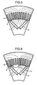
- FIG. 5 and 6 A magnetic field generated during operation of the rotary electric machine in no-load condition will be described with reference to Figs. 5 and 6 .
- Figs. 5 and 6 it is understood that the number of lines of flux passing between the rotor and the stator slots is decreased when the groove 10 is provided in comparison with the case where the groove 10 is not provided. Therefore, the groove 10 is able to block the magnetic field generated by the permanent magnets in no-load condition and thereby to reduce a no-load induced electromotive force.
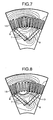
- a magnetic field generated during generating operation of the rotary electric machine in a load condition will be described with reference to Figs. 7 and 8 .
- the lines of flux move to the opposite side of the rotation direction of the rotor while passing between the rotor and the stator. Therefore, it is understood that the number of lines of flux passing between the rotor and the stator does not change even in comparison between the case where the groove 10 is provided on the opposite side of the rotation direction of the rotor and the case where the groove 10 is not provided on the opposite side, and therefore no decrease in output occurs. Therefore, even if the groove is provided on the forward side of the rotation direction which is low in the magnetic flux density, it does not block the magnetic field generated by the permanent magnets and therefore does not lead to a decrease in output.
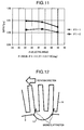
- Fig. 9 shows a plot of changes in output observed when the depth d is varied assuming that the output obtained when the groove 10 is not arranged is normalized to 1. As shown in this diagram, it is understood that the output decreases when the depth d of the groove 10 is equal to or more than 5% relative to the radial distance from the shaft center of the rotor to the rotor outer circumference.
- Fig. 10 shows a plot of changes in output observed when the angle ⁇ 1 is varied. Also in this case, the output obtained when the groove 10 is not arranged is normalized to 1. Moreover, in Fig. 10 , the effects on the angle ⁇ 1 are examined by giving three different angles to the angle ⁇ 2 as well as the angle ⁇ 1 . Here, the angle of ⁇ 2 satisfies ⁇ 2-1 ⁇ 2-2 ⁇ 2-3 . Thus, it is understood that the angle ⁇ 1 does not depend on the angle ⁇ 2 , but the output decreases if the angle ⁇ 1 exceeds 10°.
- Fig. 11 shows a plot of changes in output observed when the angle ⁇ 2 is varied. Also in this case, the output obtained when the groove 10 is not arranged is normalized to 1. Moreover, in Fig. 11 , the effects on the angle ⁇ 2 are examined by giving two different angles to the angle ⁇ 1 as well as the angle ⁇ 2 . Here, the angle of ⁇ 1 satisfies ⁇ 1-1 ⁇ 1-2 ⁇ 10°. Thus, it is understood that the angle ⁇ 2 exceeding 55° could lead to a decrease in output. As shown in Fig.
- the permanent magnet type electric generator of this embodiment it is possible to prevent a decrease in output as much as possible while reducing the no-load induced electromotive force.
- the permanent magnet type electric generator of this embodiment enables a reduction in torque pulsation caused by a magnetic force of the permanent magnets, and therefore this issue will be described hereinbelow.
- the torque pulsation caused by the magnetic force of the permanent magnets here means a phenomenon that the position of a slot provided in a rotor core or a stator core opposed to a permanent magnet used for the rotor or the stator relatively changes along with the rotations of the rotor to the permanent magnet, thereby changing a magnetic resistance between the permanent magnet and the slot, by which vibration occurs.
- the vibration causes noise at driving the rotary electric machine and, if a change gear is connected to the rotary electric machine, the vibration could lead to a reduction in gear life.
- the groove 10 is provided in the rotor outer circumference as has been described.
- torque pulsation caused by the presence of the groove 10 occurs in addition to the foregoing torque pulsation caused by the magnetic force of the permanent magnets.
- the principle is as described below.
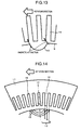
- the provision of the groove in the rotor periodically changes the magnetic resistance on the rotor side along with the rotations when viewed from the stator side. Thereby, a portion through which a magnetic flux easily passes and a portion through which a magnetic flux passes with difficulty are periodically repeated and therefore, as shown in Fig 12 and Fig. 13 , positive and negative torques occur repeatedly along with the rotations. This is the torque pulsation caused by the presence of the groove 10.
- Fig. 14 shows an enlarged part where the rotor 1 and the stator 2 are opposed to each other, and there are formed stator slots 15 and stator teeth 16 for use in winding the stator winding 4 in the stator core 14 on the stator 2 side.
- the groove 10 provided on the rotor core 5 side there are shown three-stage positions at A, B, and C with respect to the positions of the end portion 13 on the rotation direction side and the end portion 12 on the opposite side of the rotation direction with respect to the line 17 connecting the rotating center and the center of the groove as a symmetry axis.
- the position A represents an end in the rotation direction of the stator tooth 16
- the position B represents an end in the counter-rotation direction of the stator tooth 16
- the position C represents an end in the rotation direction adjacent to the position A among the ends in the rotation direction of the stator teeth 16.
- Fig. 15 shows the torque pulsation caused by a magnetic force of the permanent magnets of i)
- Fig. 16 shows a diagram plotting the first peak value in the torque pulsation caused by the presence of the groove 10 of ii) in the case of varying the position of the end portion of the groove 10.
- the end portion in a position between P1 and P2 in Fig. 16 in which the torque pulsation caused by the presence of the groove 10 of ii) first shows a positive peak value, and particularly if it is required to set a large amplitude to be canceled, it is preferable to provide the end portion close to the position B.
- the position of the end portion of the groove 10 is adjusted so that the torque pulsation caused by the presence of the groove 10 of ii) first shows a negative peak value, and if the torque pulsation caused by the magnetic force of the permanent magnets of i) first shows a negative peak value, the position of the end portion of the groove 10 is adjusted so that the torque pulsation caused by the presence of the groove 10 of ii) first shows a positive peak value, thereby enabling the torque pulsation of i) to be weakened.
- Table 1 lists the values of the output, the no-load induced electromotive force, and the torque pulsation of i) shown by the permanent magnet type electric generator when the optimal values are taken with respect to the depth, position, and the like of the foregoing groove 10, assuming that each value for a case where the groove 10 is not provided is normalized to 1.
- Groove absent Groove present Output [p.u.] 1.00 1.01
- No-load induced electromotive force [p.u.] 1.00 0.87 Cogging torque [p.u.] 1.00 0.59
- the rotor core is able to be expanded or contracted only in the radial direction when the groove 10 is absent, the provision of the groove 10 enables the expansion and contraction of the rotor core in the left-right direction according to the groove 10. This reduces the concentrated stress applied to the rotor core 5 due to the centrifugal force of the permanent magnet, thereby increasing the strength.
- the rotor 1 is formed by uniformly arranging the rotor cores 5 in the axial direction. Therefore, there is no need to stack the rotor cores, for example, with the rotor cores reversed or rotated, thereby enabling a reduction in the manufacturing cost.
- the provision of the groove 10 enables a reduction in weight of the rotor and therefore enables a reduction in weight of the entire rotary electric machine. Further, under the condition where the output can be improved in this embodiment, a more compact rotary electric machine is able to achieve predetermined output and therefore it is possible to downsize the entire rotary electric machine. In other words, it is possible to reduce the weight also from the viewpoint of downsizing.
- the rotation direction of the rotor 1 is required to be a determinate direction. It is because, if the rotation is reversed, the position of the groove 10 is located on the opposite side to the rotation direction, which makes it difficult to reduce the no-load induced electromotive force without a decrease in output.
- the position of the groove 10 as the total sum in the circumferential and axial directions is deflected toward the rotation direction from the opposite side to the rotation direction, for example, by providing the groove 10 deflected toward the rotation direction with respect to at least a part of rotor cores 5, it is possible to achieve the advantageous effect of reducing the no-load induced electromotive force while preventing a decrease in output.
- Embodiment 2 will be described below with reference to Fig. 17 .
- the permanent magnet insertion holes 6 are provided so as to form a V shape when viewed from the shaft center of the rotor 1 in Embodiment 1, whereas in this embodiment the permanent magnet insertion holes 19 in the V-shaped condition are separated farther from each other viewed from the shaft center of the rotor 1 and another permanent magnet insertion hole is provided in the central portion between the permanent magnet insertion holes.
- permanent magnets 20, 21, 22 are inserted into the permanent magnet insertion holes 19. Also in this case, it is possible to achieve the same effects as those described in Embodiment 1 under the same conditions as Embodiment 1 with respect to the groove 10.
- this embodiment has three permanent magnet insertion holes 19, in which two under the V-shaped condition are separated from each other viewed from the shaft center of the rotor 1 and another permanent magnet insertion hole is provided in the central portion therebetween, it is possible to provide four or more permanent magnet insertion holes.
- Embodiment 3 will be described below with reference to Fig. 18 .
- the permanent magnet insertion holes 19 under the V-shaped condition are separated from each other viewed from the shaft center of the rotor 1 and another permanent magnet insertion hole is provided in the central portion therebetween, whereas in this embodiment there is provided a permanent magnet insertion hole 23 which is continuous under a U-shaped condition when viewed from the shaft center of the rotor 1. It is also possible to insert a permanent magnet 24 into the permanent magnet insertion hole 23.
- Other features are the same as those of Embodiment 2 and therefore the details are omitted here.
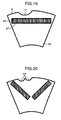
- Embodiment 4 will be described below with reference to Fig. 19 .
- a permanent magnet 28 insertion hole 27 is formed in a straight line and a permanent magnet is inserted into the permanent magnet insertion hole 27. Also with the use of this configuration, it is possible to achieve the same effects as those described in Embodiment 1 under the same conditions as Embodiment 1 with respect to the groove 10.
- Embodiment 5 will be described below with reference to Fig. 20 .
- two grooves 29 formed by dividing the groove 10 in Embodiment 1 are provided so as to be inclined toward the rotation direction relative to the line passing through the middle between the pair of permanent magnets 7 and 8 constituting a V shape from the shaft center of the rotor 1. It is possible to achieve the same effects, independently of whether one groove or a plurality of grooves, under the same conditions as described in Embodiment 1.
- a groove 30 is formed in a substantially triangular shape.
- the shape of the groove may be, for example, a groove 31, 32 of a substantially rectangular shape as shown in Figs. 22 and 23 besides the above.
- the radial cross-sectional shape of the gap is not limited to the arcuate shape, but it is also possible to use the shapes as described in the above Embodiments 2 to 5.
- Embodiment 7 will be described below with reference to Fig. 26 .
- an end portion 35 of the magnet insertion hole is formed in an arcuate shape in this embodiment. In this case, a gap exists in the permanent magnet insertion hole. Even if the gap exists in the permanent magnet insertion hole, it is possible to achieve the same effects by adopting the configuration described in the above embodiments.
- the effects of forming the end portion of the permanent magnet insertion hole into an arcuate shape are as follows: If the end portion of the permanent magnet insertion hole is flat, stress concentrates at the corner of the permanent magnet insertion hole, which may cause damage. However, the end portion is made to be arcuate, so as to avoid a damage risk. Further, although the permanent magnet insertion holes 6 are provided so as to be each arcuate and to form a V shape when viewed from the shaft center of the rotor 1 in Fig. 26 , it is also possible to form the permanent magnet insertion holes in any shape other than the V shape as described in the above embodiments.
- the end portion 36 is formed in the arcuate shape in this embodiment, besides, it is very useful to form the rotor outer circumference and the end portions 36 on the radial outsides of the permanent magnet insertion holes so as to be substantially parallel to each other, for example, as shown in Fig. 27 and Fig. 28 .
- the rotor outer circumference and the end portions 36 on the radial outsides of the permanent magnet insertion holes are formed so as to be substantially parallel to each other, it is possible to relieve the stress concentration in the vicinity of the radial most outside portion within the arcuate portion.
- Embodiment 8 will be described below with reference to Fig. 29 .
- bridge width the distances between the permanent magnet insertion hole and the rotor outer circumference
- the distances may be different in the end portions on both sides.
- a bridge width b2 on the opposite side of the rotation direction is longer than a bridge width b1 in the end portion on the rotation direction side.
- the groove is provided in a position inclined toward the rotation direction in the above embodiments and therefore the weight of the rotator core is reduced on the rotation direction side and it leads to a reduction in a centrifugal force of the magnet or a stress caused by vibration applied to the bridge portion during rotation on the rotation direction side.
- the bridge width b1 in the end portion on the rotation direction side is able to maintain the strength even if it is thin since the stress is reduced, and consequently, the bridge width b2 on the opposite side of the rotation direction is long relative to the bridge width b1 in the end portion on the rotation direction side, by which it is possible to keep balance in stress between the rotation direction side and the opposite side of the rotation direction.
- Embodiment 9 will be described below with reference to Fig. 30 .
- a divided permanent magnet 38 is inserted into one permanent magnet insertion hole. Even if the permanent magnet is divided into a plurality of parts, the same effects can be expected.
- the division of the permanent magnet is also applicable to all of the following cases: various shapes of the permanent magnet insertion hole; a groove provided in the permanent magnet insertion hole; and different bridge widths. If the division is applied, the same effects can be expected as the case where the permanent magnet is not divided.
- the rotor may be provided with a cooling use ventilation groove.
- a cooling use ventilation groove 39 may be provided in an interpolar portion of the rotor so as to connect to a gap portion between the rotor and the stator. The provision of the cooling use ventilation groove 39 in such the position increases the cooling area in the rotor and therefore enables a reduction in the temperature of the rotor.
- the cooling use ventilation groove 39 is provided so as to connect to the gap portion between the rotor and the stator, the external wall of the cooling use ventilation groove 39 in the rotor core acts like a fan, which generates fan pressure along with rotations of the rotor and thus enables a cooling air to flow effectively from the rotor toward the stator. Therefore, it is possible to improve the cooling effect of the entire rotary electric machine including the stator. Further, even if the ventilation groove is provided in the interpolar portion of the rotor, since the portion is not located between the permanent magnet and the stator winding, it is relatively difficult for the ventilation groove to interfere with the flow of the magnetic flux in a load condition and the provision of the ventilation groove does not lead to a decrease in output.
- Embodiment 11 will be described below with reference to Fig. 32 and Fig. 33 .
- the cooling use ventilation groove 39 is provided in the interpolar portion of the rotor so as to connect to the gap portion between the rotor and the stator in Embodiment 10
- axial ducts 40 communicating in the axial direction of the rotor are provided on the radially inside with respect to the permanent magnet insertion hole in this embodiment.
- a duct piece 42 communicating in the radial direction of the rotor is provided between stacked rotor cores 41, whereby a duct space 44 is formed in the position corresponding to the duct piece 42 in the axial direction in the rotor.
- the duct spaces 44 and 45 are formed both in the rotor and in the stator in this embodiment, the duct space may be provided only in the stator.
- the axial ducts 40 are provided on the radially inside of the permanent magnet in this embodiment, it is relatively difficult to interfere with the magnetic flux reaching the stator winding of the permanent magnet in a load condition and it is possible to minimize the decrease in output.
- the provision of the gap in the core portion enables a reduction in the weight of the rotor and the entire rotary electric machine.
- Embodiment 12 will be described below with reference to Fig. 34 .
- weld bead 46 for fixing the magnetic steel sheets which form the rotor cores is applied to the grooves 10. If the weld bead 46 is applied to the grooves 10, it is possible to reduce the eddy current flowing through the weld bead in comparison with the case where the weld bead is applied to the outer circumference portions other than the grooves of the rotor. The reason is now described below.
- the magnetic flux on the rotor side and the magnetic flux on the stator side exist in the gap between the rotor and the stator, which causes a large magnetic flux variation along with rotations of the rotor, and therefore the application of the weld bead to the gap between the rotor and the stator causes an eddy current, but the providing of the weld bead on the grooves spaced apart from the gap between the rotor and the stator reduces the effect of the magnetic flux variation and therefore it is possible to reduce the eddy current.
- the application of the weld bead to the grooves of the rotor reduces an air resistance during rotation in comparison with the case where the weld bead is applied to the gap and therefore it is possible to reduce rotational energy loss, thereby enabling contribution to efficiency improvement.
- the description is made on the case of applying the weld bead to the grooves in this embodiment, it goes without saying that the same effect is achieved by applying the weld bead to the gaps.
- Embodiment 13 will be described below with reference to Fig. 35 .
- description will be made on a method of manufacturing, a method of repairing, and a method of transporting the rotary electric machine described in the above embodiments.
- This embodiment is described with an example of a rotary electric machine having a bearing 17 for the rotating shaft only on one side.
- the rotary electric machine according to each of the above embodiments is provided with the grooves in the outer circumference of the rotor, and therefore it is possible to insert a guide 48, which is a support member, into the grooves or gaps.
- a guide 48 which is a support member, it is preferable to use a non-magnetic material.
- Embodiment 14 will be described below with reference to Fig. 36 .
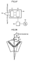
- the rotary electric machine according to each of the above embodiments is applied to an engine-motor hybrid-drive vehicle system.
- a rotary electric machine 49 is connected to an engine 50 and placed in a vehicle power car.
- the rotary electric machine 49 is connected to an electric power system 51 via an electric power converter 52 and is able to perform a generating operation.
- a battery 54 is connected to a portion between the electric power system 51 and the electric power converter 52 via a battery chopper 53. Since it is able to reduce the no-load induced electromotive force in this embodiment,, as described in the foregoing embodiments, this embodiment has a merit particularly in a reduction of risk exceeding the upper limit voltage of the electric power converter 52.
- Embodiment 15 will be described below with reference to Fig. 37 .
- a rotary electric machine 55 is connected to blades 56 via a change gear 57, and the rotary electric machine 55 and the change gear 57 are housed in a nacelle 58.
- the rotary electric machine 55 is connected to an electric power system 59 via an electric power converter 60. Since it is able to reduce the no-load induced electromotive force in this embodiment, as described in the foregoing embodiments, this embodiment has a merit particularly in a reduction of risk exceeding the upper limit voltage of the electric power converter 60.
- this embodiment enables suppression of vibration, it is possible to provide a wind turbine generator system which is low-noise and low-load on the change gear 57.
- the wind turbine generator system has been typically described in this embodiment, in addition, this embodiment is applicable to a water wheel, an engine, a turbine or the like.
- the rotary electric machine 55 is also able to be directly connected to the blades 56 without passing through the change gear 57.
- Embodiment 16 will be described below with reference to Fig. 38 .
- the rotary electric machine has been mainly described by giving an example of an electric generator in the foregoing embodiments, the present invention is also applicable to a motor. Therefore, description will be made on the position of a groove 61 for a case where the rotary electric machine is applied to the motor.
- the details other than the position of the groove 61 may be the same as those of the electric generator.
- the position of the groove 61 when the rotary electric machine is applied to the motor it is required to provide the groove 61 on the opposite side of the rotation direction.
- the magnetic flux as a combination of the magnetic flux generated by applying electric current to the stator winding and the magnetic flux generated from the permanent magnets, is generated on the opposite side to the rotation direction in the case of the electric generator
- the magnetic flux as a combination of the magnetic flux generated by applying electric current to the stator winding and the magnetic flux generated from the permanent magnets, is generated on the rotation direction side in the case of the motor.
- the position of the groove 61 is opposite to the rotation direction, the contents described in the above embodiments are similarly applicable to those of the motor.
Abstract
Description
- The present invention relates to a permanent magnet type rotary electric machine, and is particularly suitable for a rotary electric machine constant in the rotation direction. In addition, the present invention relates to a vehicle and a power generating system suitable for mounting the permanent magnet type rotary electric machine thereon.
- Recently, the permanent magnet type rotary electric machine is applied to more and more wide field of application as a high-efficiency rotary electric machine, which is capable of reducing copper loss caused by rotor winding in comparison with an induction motor, and is expected to be applied to a compressor for an air conditioner or for a refrigerator, a motor for automobile, a hybrid railway vehicle, a large generator, and the like.
- Here, as a conventional permanent magnet type rotary electric machine, there is a machine disclosed in
JP-A-2008-29095 JP-A-2001-286110 JP-A-2008-29095 JP-A-2001-286110 - When the permanent magnet type rotary electric machine is used, however, there is a problem of generation of no-load induced electromotive force. Here, description will be made on the problem caused by the generation of the no-load induced electromotive force. In the case of the permanent magnet type rotary electric machine, a magnetic field is generated without application of a load and therefore electromagnetic induction generates a voltage (no-load induced electromotive force) along with rotations of a rotor. This no-load induced electromotive force is in proportion to the number of rotations of the rotor. Therefore, if abnormal rotations of the rotor, if occurs, causes an excessive speed relative to a permissible speed, a no-load induced electromotive force exceeding a specified value is generated, which thereby causes a flow of abnormal current or a failure of a control inverter or the like. Therefore, if the permanent magnet type rotary electric machine is used, it is necessary to reduce the no-load induced electromotive force.
- According to the details described in
JP-A-2008-29095 - Moreover, according to the details described in
JP-A-2001-286110 - Therefore, it is an object of the present invention to provide a permanent magnet type rotary electric machine capable of reducing a no-load induced electromotive force and at the same time preventing a decrease in output as much as possible.
- To solve the above problem, there is provided, according to the present invention, a rotary electric machine wherein the rotation direction of a rotor is a defined direction, a groove or gap is provided on the radial outside of permanent magnets in a rotor core, and the groove or gap is provided in a position inclined from the centerline between the permanent magnets within a magnetic pole head and at the same time in a position excluding the radial outside of an end portion of a permanent magnet insertion hole.
- According to the present invention, it is possible to provide a permanent magnet type rotary electric machine capable of reducing a no-load induced electromotive force and further preventing a decrease in output.
- Other objects, features and advantages of the invention will become apparent from the following description of the embodiments of the invention taken in conjunction with the accompanying drawings.
-
-
Fig. 1 is a diagram illustrating the entire rotary electric machine according toEmbodiment 1 of the present invention; -
Fig. 2 is a diagram illustrating a cross section taken along line II-II ofFig. 1 ; -
Fig. 3 is a diagram illustrating a rotor inEmbodiment 1; -
Fig. 4 is a diagram for specifying the position of a groove inEmbodiment 1; -
Fig. 5 is a flux line diagram in no-load condition in the vicinity of a rotor and a stator in the case of the absence of the groove; -
Fig. 6 is a flux line diagram in no-load condition in the vicinity of a rotor and a stator in the case of the presence of the groove; -
Fig. 7 is a flux line diagram in a load condition in the vicinity of the rotor and the stator in the case of the absence of the groove; -
Fig. 8 is a flux line diagram in a load condition in the vicinity of the rotor and the stator in the case of the presence of the groove; -
Fig. 9 is a diagram illustrating changes in output in the case of changing the depth of the groove relative to the outside diameter of the rotor; -
Fig. 10 is a diagram illustrating changes in output in the case of changing θ1; -
Fig. 11 is a diagram illustrating changes in output in the case of changing θ2; -
Fig. 12 is a diagram for describing torque pulsation caused by the groove; -
Fig. 13 is a diagram for describing torque pulsation caused by the groove; -
Fig. 14 is a diagram for describing a condition for changing the position of the groove relative to slots of the stator; -
Fig. 15 is a diagram illustrating a displacement of torque pulsation caused by permanent magnets; -
Fig. 16 is a diagram illustrating changes in the first peak value of the torque pulsation caused by the groove when the position of the groove is changed relative to the slots of the stator; -
Fig. 17 is a radial partial cross-sectional view of a rotor according toEmbodiment 2 of the present invention; -
Fig. 18 is a radial partial cross-sectional view of a rotor according toEmbodiment 3 of the present invention; -
Fig. 19 is a radial partial cross-sectional view of a rotor according toEmbodiment 4 of the present invention; -
Fig. 20 is a radial partial cross-sectional view of a rotor according toEmbodiment 5 of the present invention; -
Fig. 21 is a radial partial cross-sectional view of a rotor according toEmbodiment 6 of the present invention; -
Fig. 22 is a radial partial cross-sectional view of a rotor according toEmbodiment 6; -
Fig. 23 is a radial partial cross-sectional view of a rotor according toEmbodiment 6; -
Fig. 24 is a radial partial cross-sectional view of a rotor according toEmbodiment 6; -
Fig. 25 is a radial partial cross-sectional view of a rotor according toEmbodiment 6; -
Fig. 26 is a radial partial cross-sectional view of a rotor according toEmbodiment 7 of the present invention; -
Fig. 27 is a radial partial cross-sectional view of a rotor according toEmbodiment 7; -
Fig. 28 is a radial partial cross-sectional view of a rotor according toEmbodiment 7; -
Fig. 29 is a radial partial cross-sectional view of a rotor according toEmbodiment 8 of the present invention; -
Fig. 30 is a radial partial cross-sectional view of a rotor according toEmbodiment 9 of the present invention; -
Fig. 31 is a radial partial cross-sectional view of a rotor according toEmbodiment 10 of the present invention; -
Fig. 32 is a radial partial cross-sectional view of a rotor according toEmbodiment 11 of the present invention; -
Fig. 33 is an axial sectional view of a rotary electric machine according to Embodiment 11; -
Fig. 34 is a diagram illustrating a rotor inEmbodiment 12 of the present invention; -
Fig. 35 is a diagram illustrating a state in which a guide is inserted into a groove with respect toEmbodiment 13 of the present invention; -
Fig. 36 is a diagram schematically illustrating an electric system of an electric train according toEmbodiment 14 of the present invention; -
Fig. 37 is a diagram schematically illustrating a state of a wind-power generation according toEmbodiment 15 of the present invention; and -
Fig. 38 is a radial partial cross-sectional view of a rotor for describing a state in which the groove is applied to a motor. - The preferred embodiments of the present invention will now be described in detail hereinafter.
-
Embodiment 1 of a permanent magnet type electric generator according to the present invention will be described below with reference toFigs. 1 to 16 and Table 1. The permanent magnet type electric generator in this embodiment mainly includes arotor 1 having a permanent magnet, arotating shaft 3 arranged in therotor 1 and concentrically with the rotor and astator 2 having a stator winding 4, which is arranged on the radial outside of therotor 1 so as to be opposed to therotor 1 and passes through thestator 2 in the axial direction. - The
rotor 1 is formed by stackingrotor cores 5 uniformly in the axial direction, where therotor cores 5 are made of magnetic steel sheets having the same shape. As shown inFig. 2 , the permanent magnet type electric generator in this embodiment is provided with permanent magnet insertion holes 6 so as to form a V shape for each magnetic pole head when viewed from the shaft center of therotor 1, andpermanent magnets arcuate groove 10 is provided in a rotorouter circumference 9 on the radial outside of the pair ofpermanent magnets groove 10 is deflected toward the rotation direction relative to the line passing through the middle between the pair ofpermanent magnets rotor 1. In addition, as shown inFig. 3 , therotor 1 is formed by arranging therotor cores 5 uniformly in the axial direction without reversing or shifting therotor cores 5. - The foregoing
groove 10 will be described below. As shown inFig. 4 , thegroove 10 is provided in a position, which is inclined toward the rotation direction relative to thecenterline 11 of the pair of permanent magnets forming the V shape extending from the shaft center of therotor 1, and at the same time in a position excluding the radial outside of the end portion of the permanent magnet insertion hole so as to have a depth d. Here, assuming that θ1 is an angle formed by anend portion 12 of thegroove 10 on the opposite side of the rotation direction and thecenterline 11 between the pair ofpermanent magnets end portion 13 of thegroove 10 on the rotation direction side and thecenterline 11 between the pair ofpermanent magnets groove 10 is provided in the position shifted toward the rotation direction. Here, the positive direction for θ1 is assumed to be the direction opposite to the rotation direction relative to thecenterline 11 between the pair ofpermanent magnets centerline 11 between the pair ofpermanent magnets - A magnetic field generated during operation of the rotary electric machine in no-load condition will be described with reference to
Figs. 5 and 6 . According toFigs. 5 and 6 , it is understood that the number of lines of flux passing between the rotor and the stator slots is decreased when thegroove 10 is provided in comparison with the case where thegroove 10 is not provided. Therefore, thegroove 10 is able to block the magnetic field generated by the permanent magnets in no-load condition and thereby to reduce a no-load induced electromotive force. - Subsequently, a magnetic field generated during generating operation of the rotary electric machine in a load condition will be described with reference to
Figs. 7 and 8 . According toFigs. 7 and 8 , the lines of flux move to the opposite side of the rotation direction of the rotor while passing between the rotor and the stator. Therefore, it is understood that the number of lines of flux passing between the rotor and the stator does not change even in comparison between the case where thegroove 10 is provided on the opposite side of the rotation direction of the rotor and the case where thegroove 10 is not provided on the opposite side, and therefore no decrease in output occurs. Therefore, even if the groove is provided on the forward side of the rotation direction which is low in the magnetic flux density, it does not block the magnetic field generated by the permanent magnets and therefore does not lead to a decrease in output. - The following discusses the depth d of the
groove 10 relative to the radial distance from the shaft center of the rotor to the rotor outer circumference.Fig. 9 shows a plot of changes in output observed when the depth d is varied assuming that the output obtained when thegroove 10 is not arranged is normalized to 1. As shown in this diagram, it is understood that the output decreases when the depth d of thegroove 10 is equal to or more than 5% relative to the radial distance from the shaft center of the rotor to the rotor outer circumference. In other words, it is possible to prevent a decrease in output as much as possible while reducing the no-load induced electromotive force by providing thegroove 10, but particularly if the depth d of thegroove 10 is less than 5% relative to the radial distance from the shaft center of the rotor to the rotor outer circumference, it is possible to reduce the no-load induced electromotive force without a decrease in output. - Subsequently, the arranged position of the
groove 10 will be discussed focusing on the angles θ1 and θ2.Fig. 10 shows a plot of changes in output observed when the angle θ1 is varied. Also in this case, the output obtained when thegroove 10 is not arranged is normalized to 1. Moreover, inFig. 10 , the effects on the angle θ1 are examined by giving three different angles to the angle θ2 as well as the angle θ1. Here, the angle of θ2 satisfies θ2-1<θ2-2<θ2-3. Thus, it is understood that the angle θ1 does not depend on the angle θ2, but the output decreases if the angle θ1 exceeds 10°. In other words, it is possible to prevent a decrease in output as much as possible while reducing the no-load induced electromotive force by providing thegroove 10, and particularly if the angle θ1 is less than 10°, it is possible to reduce the no-load induced electromotive force without a decrease in output. -
Fig. 11 shows a plot of changes in output observed when the angle θ2 is varied. Also in this case, the output obtained when thegroove 10 is not arranged is normalized to 1. Moreover, inFig. 11 , the effects on the angle θ2 are examined by giving two different angles to the angle θ1 as well as the angle θ2. Here, the angle of θ1 satisfies θ1-1<θ1-2<10°. Thus, it is understood that the angle θ2 exceeding 55° could lead to a decrease in output. As shown inFig. 11 , it is possible to prevent a decrease in output as much as possible while reducing the no-load induced electromotive force by providing thegroove 10, and particularly if the angle θ2 is less than 55°, it is possible to reduce the no-load induced electromotive force while increasing the output very advantageously. - As described above, according to the permanent magnet type electric generator of this embodiment, it is possible to prevent a decrease in output as much as possible while reducing the no-load induced electromotive force. In addition, the permanent magnet type electric generator of this embodiment enables a reduction in torque pulsation caused by a magnetic force of the permanent magnets, and therefore this issue will be described hereinbelow. The torque pulsation caused by the magnetic force of the permanent magnets here means a phenomenon that the position of a slot provided in a rotor core or a stator core opposed to a permanent magnet used for the rotor or the stator relatively changes along with the rotations of the rotor to the permanent magnet, thereby changing a magnetic resistance between the permanent magnet and the slot, by which vibration occurs. The vibration causes noise at driving the rotary electric machine and, if a change gear is connected to the rotary electric machine, the vibration could lead to a reduction in gear life.
- In the permanent magnet type electric generator according to this embodiment, the
groove 10 is provided in the rotor outer circumference as has been described. As a result, torque pulsation caused by the presence of thegroove 10 occurs in addition to the foregoing torque pulsation caused by the magnetic force of the permanent magnets. The principle is as described below. The provision of the groove in the rotor periodically changes the magnetic resistance on the rotor side along with the rotations when viewed from the stator side. Thereby, a portion through which a magnetic flux easily passes and a portion through which a magnetic flux passes with difficulty are periodically repeated and therefore, as shown inFig 12 andFig. 13 , positive and negative torques occur repeatedly along with the rotations. This is the torque pulsation caused by the presence of thegroove 10. - In addition, principles of generation differ between the two different types of torque pulsations: i) torque pulsation caused by the magnetic force of the permanent magnets; and ii) torque pulsation caused by the presence of the
groove 10. Therefore, the torque pulsations vibrate with different amplitudes and different phases independent of each other. In other words, it is possible to cancel the torque pulsation of i) which inevitably occurs in the case of using permanent magnets by forming a state of superposed vibrations which are ideally the same in amplitude as each other and opposite in phase to each other. - Hereinafter, a method of suppressing torque pulsation of i) will be described with reference to
Fig. 14 to Fig. 16 .Fig. 14 shows an enlarged part where therotor 1 and thestator 2 are opposed to each other, and there are formedstator slots 15 andstator teeth 16 for use in winding the stator winding 4 in thestator core 14 on thestator 2 side. In thegroove 10 provided on therotor core 5 side, there are shown three-stage positions at A, B, and C with respect to the positions of theend portion 13 on the rotation direction side and theend portion 12 on the opposite side of the rotation direction with respect to theline 17 connecting the rotating center and the center of the groove as a symmetry axis. Here, the position A represents an end in the rotation direction of thestator tooth 16, the position B represents an end in the counter-rotation direction of thestator tooth 16, and the position C represents an end in the rotation direction adjacent to the position A among the ends in the rotation direction of thestator teeth 16.Fig. 15 shows the torque pulsation caused by a magnetic force of the permanent magnets of i), andFig. 16 shows a diagram plotting the first peak value in the torque pulsation caused by the presence of thegroove 10 of ii) in the case of varying the position of the end portion of thegroove 10. Specifically, if the torque pulsation caused by the magnetic force of the permanent magnets of i) first shows a negative peak value, it is preferable to provide the end portion in a position between P1 and P2 inFig. 16 in which the torque pulsation caused by the presence of thegroove 10 of ii) first shows a positive peak value, and particularly if it is required to set a large amplitude to be canceled, it is preferable to provide the end portion close to the position B. In this manner, if the torque pulsation caused by the magnetic force of the permanent magnets of i) first shows a positive peak value, the position of the end portion of thegroove 10 is adjusted so that the torque pulsation caused by the presence of thegroove 10 of ii) first shows a negative peak value, and if the torque pulsation caused by the magnetic force of the permanent magnets of i) first shows a negative peak value, the position of the end portion of thegroove 10 is adjusted so that the torque pulsation caused by the presence of thegroove 10 of ii) first shows a positive peak value, thereby enabling the torque pulsation of i) to be weakened. Moreover, when the positive or negative peak value is taken, the position of the end portion of thegroove 10 is adjusted so that the absolute value of the amplitude is equal to or close to the absolute value of the amplitude of the torque pulsation of i), thereby enabling the torque pulsation of i) to be further weakened.
Table 1 lists the values of the output, the no-load induced electromotive force, and the torque pulsation of i) shown by the permanent magnet type electric generator when the optimal values are taken with respect to the depth, position, and the like of the foregoinggroove 10, assuming that each value for a case where thegroove 10 is not provided is normalized to 1.[Table 1] Groove absent Groove present Output [p.u.] 1.00 1.01 No-load induced electromotive force [p.u.] 1.00 0.87 Cogging torque [p.u.] 1.00 0.59 - As apparent from Table 1, the output does not decrease, rather slightly increases, and the no-load induced electromotive force and the torque pulsation are remarkably reduced.
- Further effects of providing the
groove 10 are as follows: it is possible to decrease the weight of therotor core 5 by providing thegroove 10, to decrease peak stress applied to therotor core 5 due to a centrifugal force during rotation, and further to improve the strength of the permanent magnet type electric generator. - Moreover, although the rotor core is able to be expanded or contracted only in the radial direction when the
groove 10 is absent, the provision of thegroove 10 enables the expansion and contraction of the rotor core in the left-right direction according to thegroove 10. This reduces the concentrated stress applied to therotor core 5 due to the centrifugal force of the permanent magnet, thereby increasing the strength. - Although this embodiment has been described for a case of the rotary electric machine having eight poles as the number of magnetic poles as shown in
Fig. 2 ,Fig. 3 , and the like, it goes without saying that the present invention is applicable to any other number of poles. - In this embodiment, the
rotor 1 is formed by uniformly arranging therotor cores 5 in the axial direction. Therefore, there is no need to stack the rotor cores, for example, with the rotor cores reversed or rotated, thereby enabling a reduction in the manufacturing cost. - Moreover, in this embodiment, the provision of the
groove 10 enables a reduction in weight of the rotor and therefore enables a reduction in weight of the entire rotary electric machine. Further, under the condition where the output can be improved in this embodiment, a more compact rotary electric machine is able to achieve predetermined output and therefore it is possible to downsize the entire rotary electric machine. In other words, it is possible to reduce the weight also from the viewpoint of downsizing. - Moreover, in this embodiment, the rotation direction of the
rotor 1 is required to be a determinate direction. It is because, if the rotation is reversed, the position of thegroove 10 is located on the opposite side to the rotation direction, which makes it difficult to reduce the no-load induced electromotive force without a decrease in output. - Moreover, it is desirable, from the viewpoint of the manufacturing cost, to provide the
groove 10 deflected toward the rotation direction with respect to all of the stackedrotor cores 5 and to form it uniformly in the same shape over the rotor covers in the axial direction so that the effect of reducing the no-load induced electromotive force is enhanced and only one type ofrotor cores 5 need to be manufactured. If, however, the position of thegroove 10 as the total sum in the circumferential and axial directions is deflected toward the rotation direction from the opposite side to the rotation direction, for example, by providing thegroove 10 deflected toward the rotation direction with respect to at least a part ofrotor cores 5, it is possible to achieve the advantageous effect of reducing the no-load induced electromotive force while preventing a decrease in output. -
Embodiment 2 will be described below with reference toFig. 17 . The permanent magnet insertion holes 6 are provided so as to form a V shape when viewed from the shaft center of therotor 1 inEmbodiment 1, whereas in this embodiment the permanent magnet insertion holes 19 in the V-shaped condition are separated farther from each other viewed from the shaft center of therotor 1 and another permanent magnet insertion hole is provided in the central portion between the permanent magnet insertion holes. In addition,permanent magnets Embodiment 1 under the same conditions asEmbodiment 1 with respect to thegroove 10. - Although this embodiment has three permanent magnet insertion holes 19, in which two under the V-shaped condition are separated from each other viewed from the shaft center of the
rotor 1 and another permanent magnet insertion hole is provided in the central portion therebetween, it is possible to provide four or more permanent magnet insertion holes. -
Embodiment 3 will be described below with reference toFig. 18 . InEmbodiment 2, the permanent magnet insertion holes 19 under the V-shaped condition are separated from each other viewed from the shaft center of therotor 1 and another permanent magnet insertion hole is provided in the central portion therebetween, whereas in this embodiment there is provided a permanentmagnet insertion hole 23 which is continuous under a U-shaped condition when viewed from the shaft center of therotor 1. It is also possible to insert apermanent magnet 24 into the permanentmagnet insertion hole 23. Other features are the same as those ofEmbodiment 2 and therefore the details are omitted here. -
Embodiment 4 will be described below with reference toFig. 19 . In this embodiment, apermanent magnet 28insertion hole 27 is formed in a straight line and a permanent magnet is inserted into the permanentmagnet insertion hole 27. Also with the use of this configuration, it is possible to achieve the same effects as those described inEmbodiment 1 under the same conditions asEmbodiment 1 with respect to thegroove 10. -
Embodiment 5 will be described below with reference toFig. 20 . In this embodiment, twogrooves 29 formed by dividing thegroove 10 inEmbodiment 1 are provided so as to be inclined toward the rotation direction relative to the line passing through the middle between the pair ofpermanent magnets rotor 1. It is possible to achieve the same effects, independently of whether one groove or a plurality of grooves, under the same conditions as described inEmbodiment 1. -
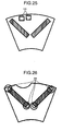
Embodiment 6 will be described below with reference toFig. 21 . In this embodiment, agroove 30 is formed in a substantially triangular shape. The shape of the groove may be, for example, agroove Figs. 22 and23 besides the above. It is also possible to form anarcuate gap 33 formed in the axial direction inside the rotor core, instead of the groove, as shown inFig. 24 . The radial cross-sectional shape of the gap is not limited to the arcuate shape, but it is also possible to use the shapes as described in theabove Embodiments 2 to 5. In addition, as shown inFig. 25 , it is possible to provide a plurality ofgaps 34. -
Embodiment 7 will be described below with reference toFig. 26 . Although any gap is not provided in the permanent magnet insertion hole in the above embodiments, anend portion 35 of the magnet insertion hole is formed in an arcuate shape in this embodiment. In this case, a gap exists in the permanent magnet insertion hole. Even if the gap exists in the permanent magnet insertion hole, it is possible to achieve the same effects by adopting the configuration described in the above embodiments. - Further, the effects of forming the end portion of the permanent magnet insertion hole into an arcuate shape are as follows: If the end portion of the permanent magnet insertion hole is flat, stress concentrates at the corner of the permanent magnet insertion hole, which may cause damage. However, the end portion is made to be arcuate, so as to avoid a damage risk. Further, although the permanent magnet insertion holes 6 are provided so as to be each arcuate and to form a V shape when viewed from the shaft center of the
rotor 1 inFig. 26 , it is also possible to form the permanent magnet insertion holes in any shape other than the V shape as described in the above embodiments. - Moreover, although the description has been made on only an example that the
end portion 36 is formed in the arcuate shape in this embodiment, besides, it is very useful to form the rotor outer circumference and theend portions 36 on the radial outsides of the permanent magnet insertion holes so as to be substantially parallel to each other, for example, as shown inFig. 27 and Fig. 28 . This is based on the following fact: Though the arcuate end portion can relieve the stress concentration at the corner of the permanent magnet insertion hole, another stress concentration occurs in the vicinity of the radial most outside portion within the arcuate portion. On the contrary, when the rotor outer circumference and theend portions 36 on the radial outsides of the permanent magnet insertion holes are formed so as to be substantially parallel to each other, it is possible to relieve the stress concentration in the vicinity of the radial most outside portion within the arcuate portion. Additionally, it is also possible to employ other configurations for relieving stress concentration, as well as a case in which a type that the rotor outer circumference and theend portions 36 on the radial outsides of the permanent magnet insertion holes are formed so as to be substantially parallel to each other and another type that the end portions are formed each in an arcuate shape are mixed depending on the rotation direction or counter-rotation direction, and further depending on the radial outside or inside. -
Embodiment 8 will be described below with reference toFig. 29 . Although the distances between the permanent magnet insertion hole and the rotor outer circumference (hereinafter, referred to as "bridge width") are the same in the end portion on the rotation direction side of the permanent magnet insertion hole and in the end portion on the opposite side of the rotation direction in the above embodiments, the distances may be different in the end portions on both sides. InFig. 29 , particularly a bridge width b2 on the opposite side of the rotation direction is longer than a bridge width b1 in the end portion on the rotation direction side. This is based on the consideration that the groove is provided in a position inclined toward the rotation direction in the above embodiments and therefore the weight of the rotator core is reduced on the rotation direction side and it leads to a reduction in a centrifugal force of the magnet or a stress caused by vibration applied to the bridge portion during rotation on the rotation direction side. More specifically, the bridge width b1 in the end portion on the rotation direction side is able to maintain the strength even if it is thin since the stress is reduced, and consequently, the bridge width b2 on the opposite side of the rotation direction is long relative to the bridge width b1 in the end portion on the rotation direction side, by which it is possible to keep balance in stress between the rotation direction side and the opposite side of the rotation direction. -
Embodiment 9 will be described below with reference toFig. 30 . In this embodiment, a dividedpermanent magnet 38 is inserted into one permanent magnet insertion hole. Even if the permanent magnet is divided into a plurality of parts, the same effects can be expected. Moreover, the division of the permanent magnet is also applicable to all of the following cases: various shapes of the permanent magnet insertion hole; a groove provided in the permanent magnet insertion hole; and different bridge widths. If the division is applied, the same effects can be expected as the case where the permanent magnet is not divided. -
Embodiment 10 will be described below with reference toFig. 31 . The rotor may be provided with a cooling use ventilation groove. This leads to an improvement of the cooling effect of the rotor. Particularly, as in this embodiment, a coolinguse ventilation groove 39 may be provided in an interpolar portion of the rotor so as to connect to a gap portion between the rotor and the stator. The provision of the coolinguse ventilation groove 39 in such the position increases the cooling area in the rotor and therefore enables a reduction in the temperature of the rotor. Moreover, since the coolinguse ventilation groove 39 is provided so as to connect to the gap portion between the rotor and the stator, the external wall of the coolinguse ventilation groove 39 in the rotor core acts like a fan, which generates fan pressure along with rotations of the rotor and thus enables a cooling air to flow effectively from the rotor toward the stator. Therefore, it is possible to improve the cooling effect of the entire rotary electric machine including the stator. Further, even if the ventilation groove is provided in the interpolar portion of the rotor, since the portion is not located between the permanent magnet and the stator winding, it is relatively difficult for the ventilation groove to interfere with the flow of the magnetic flux in a load condition and the provision of the ventilation groove does not lead to a decrease in output. -
Embodiment 11 will be described below with reference toFig. 32 andFig. 33 . Although the coolinguse ventilation groove 39 is provided in the interpolar portion of the rotor so as to connect to the gap portion between the rotor and the stator inEmbodiment 10,axial ducts 40 communicating in the axial direction of the rotor are provided on the radially inside with respect to the permanent magnet insertion hole in this embodiment. Moreover, as shown inFig. 33 , aduct piece 42 communicating in the radial direction of the rotor is provided betweenstacked rotor cores 41, whereby aduct space 44 is formed in the position corresponding to theduct piece 42 in the axial direction in the rotor. Thereby, a cooling air supplied from the fan is pushed from theduct space 44 to the outside of the rotor through theaxial ducts duct spaces axial ducts 40 are provided on the radially inside of the permanent magnet in this embodiment, it is relatively difficult to interfere with the magnetic flux reaching the stator winding of the permanent magnet in a load condition and it is possible to minimize the decrease in output. In addition, the provision of the gap in the core portion enables a reduction in the weight of the rotor and the entire rotary electric machine. -
Embodiment 12 will be described below with reference toFig. 34 . InEmbodiment 12,weld bead 46 for fixing the magnetic steel sheets which form the rotor cores is applied to thegrooves 10. If theweld bead 46 is applied to thegrooves 10, it is possible to reduce the eddy current flowing through the weld bead in comparison with the case where the weld bead is applied to the outer circumference portions other than the grooves of the rotor. The reason is now described below. Specifically, the magnetic flux on the rotor side and the magnetic flux on the stator side exist in the gap between the rotor and the stator, which causes a large magnetic flux variation along with rotations of the rotor, and therefore the application of the weld bead to the gap between the rotor and the stator causes an eddy current, but the providing of the weld bead on the grooves spaced apart from the gap between the rotor and the stator reduces the effect of the magnetic flux variation and therefore it is possible to reduce the eddy current. Furthermore, the application of the weld bead to the grooves of the rotor reduces an air resistance during rotation in comparison with the case where the weld bead is applied to the gap and therefore it is possible to reduce rotational energy loss, thereby enabling contribution to efficiency improvement. Although the description is made on the case of applying the weld bead to the grooves in this embodiment, it goes without saying that the same effect is achieved by applying the weld bead to the gaps. -
Embodiment 13 will be described below with reference toFig. 35 . In this embodiment, description will be made on a method of manufacturing, a method of repairing, and a method of transporting the rotary electric machine described in the above embodiments. This embodiment is described with an example of a rotary electric machine having a bearing 17 for the rotating shaft only on one side. In this case, the rotary electric machine according to each of the above embodiments is provided with the grooves in the outer circumference of the rotor, and therefore it is possible to insert aguide 48, which is a support member, into the grooves or gaps. Here, for theguide 48, it is preferable to use a non-magnetic material. It is because, if a magnetic guide is used, the guide is attracted to the magnetic force of the permanent magnets, which makes it difficult to insert and extract the guide. The insertion of the guide into the grooves fixes the rotor, thereby enabling prevention of rotations of the rotor and prevention of a contact between the rotor and the stator during manufacturing or transportation of the rotary electric machine. Specifically, if the rotary electric machine is manufactured, repaired, or transported with theguide 48, particularly made of non-magnetic material, inserted in the grooves, there is no need to particularly provide any other structure for fixing the rotor, which makes it possible to use the existence of the grooves effectively. Also in the case of a rotary electric machine having bearings on both sides, this embodiment is applicable when both sides are not sealed such as during manufacturing or repairing. -
Embodiment 14 will be described below with reference toFig. 36 . In this embodiment, the rotary electric machine according to each of the above embodiments is applied to an engine-motor hybrid-drive vehicle system. In this embodiment, a rotaryelectric machine 49 is connected to anengine 50 and placed in a vehicle power car. The rotaryelectric machine 49 is connected to anelectric power system 51 via anelectric power converter 52 and is able to perform a generating operation. Moreover, abattery 54 is connected to a portion between theelectric power system 51 and theelectric power converter 52 via abattery chopper 53. Since it is able to reduce the no-load induced electromotive force in this embodiment,, as described in the foregoing embodiments, this embodiment has a merit particularly in a reduction of risk exceeding the upper limit voltage of theelectric power converter 52. -
Embodiment 15 will be described below with reference toFig. 37 . In this embodiment, there is shown an example of applying the rotary electric machine according to each of the above embodiments to a wind turbine generator system. In this embodiment, a rotaryelectric machine 55 is connected toblades 56 via achange gear 57, and the rotaryelectric machine 55 and thechange gear 57 are housed in anacelle 58. In addition, the rotaryelectric machine 55 is connected to anelectric power system 59 via anelectric power converter 60. Since it is able to reduce the no-load induced electromotive force in this embodiment, as described in the foregoing embodiments, this embodiment has a merit particularly in a reduction of risk exceeding the upper limit voltage of theelectric power converter 60. Moreover, since this embodiment enables suppression of vibration, it is possible to provide a wind turbine generator system which is low-noise and low-load on thechange gear 57. Although the wind turbine generator system has been typically described in this embodiment, in addition, this embodiment is applicable to a water wheel, an engine, a turbine or the like. Moreover, the rotaryelectric machine 55 is also able to be directly connected to theblades 56 without passing through thechange gear 57. -
Embodiment 16 will be described below with reference toFig. 38 . Although the rotary electric machine has been mainly described by giving an example of an electric generator in the foregoing embodiments, the present invention is also applicable to a motor. Therefore, description will be made on the position of agroove 61 for a case where the rotary electric machine is applied to the motor. The details other than the position of thegroove 61 may be the same as those of the electric generator. As for the position of thegroove 61 when the rotary electric machine is applied to the motor, it is required to provide thegroove 61 on the opposite side of the rotation direction. It is because, while the magnetic flux, as a combination of the magnetic flux generated by applying electric current to the stator winding and the magnetic flux generated from the permanent magnets, is generated on the opposite side to the rotation direction in the case of the electric generator, the magnetic flux, as a combination of the magnetic flux generated by applying electric current to the stator winding and the magnetic flux generated from the permanent magnets, is generated on the rotation direction side in the case of the motor. Except for that the position of thegroove 61 is opposite to the rotation direction, the contents described in the above embodiments are similarly applicable to those of the motor. - It should be further understood by those skilled in the art that although the foregoing description has been made on embodiments of the invention, the invention is not limited thereto and various changes and modifications may be made without departing from the spirit of the invention and the scope of the appended claims.
Claims (17)
- A rotary electric machine comprising:a rotor (1) which has permanent magnets (7, 8, 20 - 22, 24, 28) inserted in permanent magnet insertion holes (6) provided in a rotor core for each magnetic pole head of the rotor core; anda stator (2) which is disposed on a radial outside so as to be opposed to the rotor,wherein a groove (10, 29 - 34, 61) or gap is provided in the rotor core on a radial outside (9) with respect to the permanent magnets and the groove or gap is provided in a position inclined from a centerline (11) between the permanent magnets within the magnetic pole head and at the same time in a position excluding end portions of the permanent magnet insertion holes on a radial outside.
- The machine according to claim 1, wherein the groove or gap (10, 29 - 34, 61) is provided in a position inclined toward the rotation direction from the centerline (11) between the permanent magnets and at the same time in a position excluding the end portions of the permanent magnet insertion holes on the radial outside.
- The machine according to claim 1, wherein the groove or gap (10, 29 - 34, 61) is provided in a position inclined toward an opposite side of the rotation direction from the centerline between the permanent magnets and at the same time in the position excluding the end portions of the permanent magnet insertion holes on the radial outside.
- The machine according to claim 2 or 3,
wherein an angle α formed by an end portion (12) of the groove or gap (10, 29 - 34, 61) on an opposite side of the rotation direction and a centerline (11) between the permanent magnets within a magnetic pole head is smaller than an angle β formed by an end portion (13) of the groove or gap on a rotation direction side and the centerline (11) between the permanent magnets within the magnetic pole head, and the angle α is less than 10, 29 - 34, 61 °. - The machine according to any one of claims 2 to 4,
wherein an angle α formed by an end portion (12) of the groove or gap (10, 29 - 34, 61) on an opposite side of the rotation direction and a centerline (11) between the permanent magnets within a magnetic pole head is smaller than an angle β formed by an end portion (13) of the groove or gap (10, 29 - 34, 61) on a rotation direction side and the centerline (11) between the permanent magnets within the magnetic pole head, and the angle P is less than 55°. - The machine according to any one of claims 2 to 5, wherein the rotation direction of the rotor is a defined direction and the entire position of the groove or gap (10, 29 - 34, 61) in the circumferential direction and the axial direction is deflected toward the rotation direction, rather than toward the opposite side in the rotation direction, relative to the centerline between the permanent magnets.
- The machine according to any one of claims 2 to 6, wherein a distance between the permanent magnet insertion hole and the rotor core outer circumference (9) on the opposite side of the rotation direction is longer than the distance on the rotation direction side.
- The machine according to any one of claims 1 to 7, wherein a non-magnetic support member is inserted in the groove or gap (10, 29 - 34, 61).
- The machine according to any one of claims 1 to 8, wherein the permanent magnet is divided into a plurality of parts.
- The machine according to any one of claims 1 to 9, wherein a plurality of said grooves or gaps (10, 29 - 34, 61) are provided.
- The machine according to any one of claims 1 to 10, wherein the end portion of the permanent magnet insertion hole on the radial outside is formed in an arcuate shape.
- The machine according to any one of claims 1 to 10, wherein the end portion of the permanent magnet insertion hole on the radial outside is substantially parallel to the outer circumference of the rotor.
- The machine according to any one of claims 1 to 12, wherein an interpolar portion of the rotor is provided with a ventilation groove, which connects to a gap between the rotor and the stator.
- The machine according to any one of claims 1 to 13, wherein a ventilation groove communicating in the axial direction of the rotor is provided in the rotor core on a radially inside with respect to the permanent magnet insertion holes.
- The machine according to any one of claims 1 to 14, wherein the rotor is formed uniformly in the same shape over an entire length in the axial direction.
- The machine according to any one of claims 1 to 15, wherein a member for fixing the rotor cores constituting the rotor is applied to the groove or gap (10, 29 - 34, 61).
- The machine according to any one of claims 1 to 16, wherein a depth (d) of the groove (10, 29 - 34, 61) is less than 5% relative to a radial distance from a shaft center of the rotor to the rotor outer circumference.
Applications Claiming Priority (1)
| Application Number | Priority Date | Filing Date | Title |
|---|---|---|---|
| JP2010001700A JP5260563B2 (en) | 2010-01-07 | 2010-01-07 | Permanent magnet generator or motor |
Publications (2)
| Publication Number | Publication Date |
|---|---|
| EP2355306A2 true EP2355306A2 (en) | 2011-08-10 |
| EP2355306A3 EP2355306A3 (en) | 2014-12-24 |
Family
ID=44147909
Family Applications (1)
| Application Number | Title | Priority Date | Filing Date |
|---|---|---|---|
| EP11000002.3A Withdrawn EP2355306A3 (en) | 2010-01-07 | 2011-01-03 | Permanent magnet type rotary electric machine |
Country Status (3)
| Country | Link |
|---|---|
| US (1) | US20110163624A1 (en) |
| EP (1) | EP2355306A3 (en) |
| JP (1) | JP5260563B2 (en) |
Cited By (5)
| Publication number | Priority date | Publication date | Assignee | Title |
|---|---|---|---|---|
| CN103855826A (en) * | 2012-11-29 | 2014-06-11 | 铃木株式会社 | IPM type rotary motor |
| EP2995820A1 (en) * | 2014-09-11 | 2016-03-16 | Pfeiffer Vacuum Gmbh | Vacuum pump with welded motor rotor and with magnets arranged in v-shape |
| US9369016B2 (en) | 2012-12-18 | 2016-06-14 | Robert Bosch Gmbh | Rotor for an electric machine comprising recesses in magnet pockets |
| CN103762760B (en) * | 2014-01-07 | 2016-07-06 | 广东美芝制冷设备有限公司 | For the motor of rotary compressor and have the rotary compressor of this motor |
| TWI711246B (en) * | 2019-06-03 | 2020-11-21 | 威剛科技股份有限公司 | Axial rotor of axial gap type electrical rotation machine |
Families Citing this family (26)
| Publication number | Priority date | Publication date | Assignee | Title |
|---|---|---|---|---|
| CN102369650B (en) * | 2010-04-01 | 2015-08-05 | 富士电机株式会社 | The rotor of permanent magnet type electric rotary machine |
| US20130057104A1 (en) * | 2011-09-02 | 2013-03-07 | Steven Stretz | Permanent magnet motors and methods of assembling the same |
| JP5647961B2 (en) * | 2011-09-26 | 2015-01-07 | 東芝三菱電機産業システム株式会社 | Rotating electric machine |
| JP2013070572A (en) * | 2011-09-26 | 2013-04-18 | Toshiba Mitsubishi-Electric Industrial System Corp | Rotary electric machine |
| JP5647962B2 (en) * | 2011-09-27 | 2015-01-07 | 東芝三菱電機産業システム株式会社 | Rotating electric machine |
| JP5594304B2 (en) * | 2012-02-13 | 2014-09-24 | 株式会社安川電機 | Rotating electric machine |
| JP5893462B2 (en) | 2012-03-26 | 2016-03-23 | 東芝三菱電機産業システム株式会社 | Rotating electric machine |
| JP5785521B2 (en) | 2012-05-10 | 2015-09-30 | 東芝三菱電機産業システム株式会社 | Rotating electric machine |
| CN103580410A (en) * | 2012-07-31 | 2014-02-12 | 成都联腾动力控制技术有限公司 | Wide-range speed control permanent magnet synchronous motor used for electric vehicle |
| US9716411B2 (en) * | 2013-01-24 | 2017-07-25 | Mitsubishi Electric Corporation | Permanent-magnet-type rotating electric mechanism |
| DE102013201199A1 (en) * | 2013-01-25 | 2014-07-31 | Magna Powertrain Ag & Co. Kg | Electric machine and method for producing an electric sheet |
| JP2014241705A (en) * | 2013-06-12 | 2014-12-25 | 株式会社ジェイテクト | Magnet embedded rotor |
| JP6174150B2 (en) * | 2013-08-05 | 2017-08-02 | 三菱電機株式会社 | Permanent magnet embedded rotary electric machine |
| JP2015142386A (en) * | 2014-01-27 | 2015-08-03 | 日立オートモティブシステムズ株式会社 | Rotor for rotary electric machine, rotary electric machine employing the same, and electric vehicle |
| JP5872605B2 (en) * | 2014-03-04 | 2016-03-01 | ダイキン工業株式会社 | Rotor |
| CN103956872B (en) * | 2014-04-25 | 2018-07-20 | 联合汽车电子有限公司 | Permanent magnet synchronous motor and its rotor |
| US9985484B2 (en) * | 2015-06-09 | 2018-05-29 | Ford Global Technologies, Llc | Surface groove patterns for permanent magnet machine rotors |
| EP3413440B1 (en) | 2017-06-06 | 2023-05-31 | GE Renewable Technologies Wind B.V. | Magnet module and electrical machine |
| CN107070032A (en) * | 2017-06-23 | 2017-08-18 | 江苏航天动力机电有限公司 | New-energy automobile wheel hub motor rotor punching |
| US10432047B2 (en) * | 2017-07-31 | 2019-10-01 | Ford Global Technologies, Llc | Asymmetrical surface groove patterns for permanent magnet machine rotors |
| JP7022282B2 (en) * | 2019-03-28 | 2022-02-18 | ダイキン工業株式会社 | Motor and motor system with it |
| CN110752685A (en) * | 2019-09-30 | 2020-02-04 | 华为技术有限公司 | Rotor iron chip, rotor iron core, rotor, permanent magnet synchronous motor and related products |
| KR20210043079A (en) * | 2019-10-11 | 2021-04-21 | 현대자동차주식회사 | Motor having asymmetry rotor core |
| WO2021095167A1 (en) * | 2019-11-13 | 2021-05-20 | 三菱電機株式会社 | Dynamo-electric machine |
| CN111769670A (en) * | 2020-07-16 | 2020-10-13 | 精进电动科技股份有限公司 | Rotor core of segmented skewed-pole motor and permanent magnet synchronous motor |
| DE102021202726A1 (en) | 2021-03-22 | 2022-09-22 | Zf Friedrichshafen Ag | Electrical machine and method for manufacturing an electrical machine |
Citations (2)
| Publication number | Priority date | Publication date | Assignee | Title |
|---|---|---|---|---|
| JP2001286110A (en) | 2000-03-31 | 2001-10-12 | Toshiba Corp | Rotating electric machine of permanent-magnetic reluctance type |
| JP2008029095A (en) | 2006-07-20 | 2008-02-07 | Hitachi Industrial Equipment Systems Co Ltd | Permanent magnet type dynamo-electric machine and compressor using the same |
Family Cites Families (17)
| Publication number | Priority date | Publication date | Assignee | Title |
|---|---|---|---|---|
| JP3487667B2 (en) * | 1995-03-15 | 2004-01-19 | 松下電器産業株式会社 | Rotor structure |
| JPH08275418A (en) * | 1995-03-29 | 1996-10-18 | Nippon Seiko Kk | Five-phase brushless motor |
| JP3625170B2 (en) * | 2000-03-22 | 2005-03-02 | ジヤトコ株式会社 | Hybrid vehicle transmission unit |
| JP2002101586A (en) * | 2000-09-25 | 2002-04-05 | Toshiba Kyaria Kk | Rotor of electric motor |
| JP4356232B2 (en) * | 2000-11-22 | 2009-11-04 | 株式会社デンソー | Rotor center of gravity eccentric type motor |
| WO2002071577A1 (en) * | 2001-03-07 | 2002-09-12 | Hitachi, Ltd. | Rotary electric machinery |
| DE60322016D1 (en) * | 2003-02-18 | 2008-08-21 | Minebea Co Ltd | Rotor and stator of an electric machine with reduced pulsating moment |
| JP2004289905A (en) * | 2003-03-20 | 2004-10-14 | Isuzu Motors Ltd | Rotary electric machine |
| JP4490047B2 (en) * | 2003-04-28 | 2010-06-23 | トヨタ自動車株式会社 | Electric motor |
| JP4311182B2 (en) * | 2003-12-08 | 2009-08-12 | 日産自動車株式会社 | Rotating electric machine rotor |
| JP4449035B2 (en) * | 2004-03-10 | 2010-04-14 | 日立オートモティブシステムズ株式会社 | Permanent magnet rotating electric machine for electric vehicles |
| JP4572647B2 (en) * | 2004-10-01 | 2010-11-04 | 株式会社日立製作所 | Permanent magnet rotating electrical machine and wind power generation system |
| JP2007097387A (en) * | 2005-08-31 | 2007-04-12 | Toshiba Corp | Rotary electric machine |
| JP5157138B2 (en) * | 2006-11-24 | 2013-03-06 | 株式会社日立製作所 | Permanent magnet rotating electrical machine and wind power generation system |
| JP4372798B2 (en) * | 2007-02-13 | 2009-11-25 | アスモ株式会社 | Embedded magnet type motor |
| JP4844570B2 (en) * | 2008-01-16 | 2011-12-28 | 三菱電機株式会社 | Permanent magnet type motor |
| JP2009219331A (en) * | 2008-03-13 | 2009-09-24 | Hitachi Ltd | Permanent magnet type generator and hybrid vehicle using the same |
-
2010
- 2010-01-07 JP JP2010001700A patent/JP5260563B2/en active Active
-
2011
- 2011-01-03 EP EP11000002.3A patent/EP2355306A3/en not_active Withdrawn
- 2011-01-05 US US12/984,624 patent/US20110163624A1/en not_active Abandoned
Patent Citations (2)
| Publication number | Priority date | Publication date | Assignee | Title |
|---|---|---|---|---|
| JP2001286110A (en) | 2000-03-31 | 2001-10-12 | Toshiba Corp | Rotating electric machine of permanent-magnetic reluctance type |
| JP2008029095A (en) | 2006-07-20 | 2008-02-07 | Hitachi Industrial Equipment Systems Co Ltd | Permanent magnet type dynamo-electric machine and compressor using the same |
Cited By (6)
| Publication number | Priority date | Publication date | Assignee | Title |
|---|---|---|---|---|
| CN103855826A (en) * | 2012-11-29 | 2014-06-11 | 铃木株式会社 | IPM type rotary motor |
| CN103855826B (en) * | 2012-11-29 | 2016-06-08 | 铃木株式会社 | IPM rotary motor |
| US9369016B2 (en) | 2012-12-18 | 2016-06-14 | Robert Bosch Gmbh | Rotor for an electric machine comprising recesses in magnet pockets |
| CN103762760B (en) * | 2014-01-07 | 2016-07-06 | 广东美芝制冷设备有限公司 | For the motor of rotary compressor and have the rotary compressor of this motor |
| EP2995820A1 (en) * | 2014-09-11 | 2016-03-16 | Pfeiffer Vacuum Gmbh | Vacuum pump with welded motor rotor and with magnets arranged in v-shape |
| TWI711246B (en) * | 2019-06-03 | 2020-11-21 | 威剛科技股份有限公司 | Axial rotor of axial gap type electrical rotation machine |
Also Published As
| Publication number | Publication date |
|---|---|
| JP5260563B2 (en) | 2013-08-14 |
| EP2355306A3 (en) | 2014-12-24 |
| JP2011142735A (en) | 2011-07-21 |
| US20110163624A1 (en) | 2011-07-07 |
Similar Documents
| Publication | Publication Date | Title |
|---|---|---|
| EP2355306A2 (en) | Permanent magnet type rotary electric machine | |
| JP4404223B2 (en) | Electromagnetic steel sheet forming body, electromagnetic steel sheet laminate, permanent magnet type synchronous rotating electric machine equipped with the same, permanent magnet type synchronous rotating electric machine, vehicle using the rotating electric machine, elevator, fluid machine, processing machine | |
| EP2418756B1 (en) | Permanent magnet rotating electric machine | |
| US7804216B2 (en) | Permanent-magnet reluctance electrical rotary machine | |
| JP5059614B2 (en) | Structure of magnet and web in permanent magnet embedded rotor | |
| US8896175B2 (en) | Rotor of an electric machine with embedded permanent magnets and electric machine | |
| US9071118B2 (en) | Axial motor | |
| EP2403107B1 (en) | Permanent magnet type rotary machine | |
| US20070228861A1 (en) | Electrical Rotary Machine and Electromagnetic Apparatus | |
| US9871420B2 (en) | Rotor for a rotary electric machine and rotary electric machine comprising such a rotor | |
| US20050093388A1 (en) | Motor | |
| US8760026B2 (en) | Rotor with V-shaped permanent magnet arrangement, rotating electric machine, vehicle, elevator, fluid machine, and processing machine | |
| EP3082224B1 (en) | System and method for supporting laminations of synchronous reluctance motors | |
| CN105324918A (en) | Rotating electric machine | |
| JP2010045974A (en) | Permanent magnet type synchronous rotating electric machine, and vehicle, elevator, fluid machinery and processing machine equipped with same | |
| US20220216751A1 (en) | Rotor for rotating electric machine | |
| JP5082825B2 (en) | Rotor for embedded magnet type rotating electrical machine, embedded magnet type rotating electrical machine, vehicle, elevator, fluid machine, processing machine using the rotating electrical machine | |
| JP5679695B2 (en) | Permanent magnet rotating electric machine | |
| US8593028B2 (en) | Magnet for a generator | |
| JP2014082836A (en) | Rotor and rotary electric machine having the same | |
| CN112886739B (en) | Rotor core, motor rotor, motor | |
| JP2009296882A (en) | Synchronous rotating electric machine in permanent magnet shape, and vehicle, elevator, fluid machinery and processing machine equipped therewith | |
| JP2014082832A (en) | Rotor and rotary electric machine having the same | |
| KR20210120354A (en) | Electric motor and electric vehicle having the same | |
| JP2015053778A (en) | Synchronous motor, and rotor for use in the same |
Legal Events
| Date | Code | Title | Description |
|---|---|---|---|
| PUAI | Public reference made under article 153(3) epc to a published international application that has entered the european phase |
Free format text: ORIGINAL CODE: 0009012 |
|
| AK | Designated contracting states |
Kind code of ref document: A2 Designated state(s): AL AT BE BG CH CY CZ DE DK EE ES FI FR GB GR HR HU IE IS IT LI LT LU LV MC MK MT NL NO PL PT RO RS SE SI SK SM TR |
|
| AX | Request for extension of the european patent |
Extension state: BA ME |
|
| 17P | Request for examination filed |
Effective date: 20110805 |
|
| PUAL | Search report despatched |
Free format text: ORIGINAL CODE: 0009013 |
|
| AK | Designated contracting states |
Kind code of ref document: A3 Designated state(s): AL AT BE BG CH CY CZ DE DK EE ES FI FR GB GR HR HU IE IS IT LI LT LU LV MC MK MT NL NO PL PT RO RS SE SI SK SM TR |
|
| AX | Request for extension of the european patent |
Extension state: BA ME |
|
| RIC1 | Information provided on ipc code assigned before grant |
Ipc: H02K 1/27 20060101AFI20141117BHEP Ipc: H02K 7/18 20060101ALN20141117BHEP |
|
| STAA | Information on the status of an ep patent application or granted ep patent |
Free format text: STATUS: THE APPLICATION HAS BEEN WITHDRAWN |
|
| 18W | Application withdrawn |
Effective date: 20150102 |