EP2355296A1 - Circuit for use with energy converter - Google Patents
Circuit for use with energy converter Download PDFInfo
- Publication number
- EP2355296A1 EP2355296A1 EP11152181A EP11152181A EP2355296A1 EP 2355296 A1 EP2355296 A1 EP 2355296A1 EP 11152181 A EP11152181 A EP 11152181A EP 11152181 A EP11152181 A EP 11152181A EP 2355296 A1 EP2355296 A1 EP 2355296A1
- Authority
- EP
- European Patent Office
- Prior art keywords
- switch
- discharge resistor
- voltage
- capacitor
- discharge
- Prior art date
- Legal status (The legal status is an assumption and is not a legal conclusion. Google has not performed a legal analysis and makes no representation as to the accuracy of the status listed.)
- Granted
Links
Images


Classifications
-
- H—ELECTRICITY
- H02—GENERATION; CONVERSION OR DISTRIBUTION OF ELECTRIC POWER
- H02M—APPARATUS FOR CONVERSION BETWEEN AC AND AC, BETWEEN AC AND DC, OR BETWEEN DC AND DC, AND FOR USE WITH MAINS OR SIMILAR POWER SUPPLY SYSTEMS; CONVERSION OF DC OR AC INPUT POWER INTO SURGE OUTPUT POWER; CONTROL OR REGULATION THEREOF
- H02M7/00—Conversion of AC power input into DC power output; Conversion of DC power input into AC power output
- H02M7/42—Conversion of DC power input into AC power output without possibility of reversal
- H02M7/44—Conversion of DC power input into AC power output without possibility of reversal by static converters
- H02M7/48—Conversion of DC power input into AC power output without possibility of reversal by static converters using discharge tubes with control electrode or semiconductor devices with control electrode
- H02M7/483—Converters with outputs that each can have more than two voltages levels
-
- H—ELECTRICITY
- H02—GENERATION; CONVERSION OR DISTRIBUTION OF ELECTRIC POWER
- H02J—ELECTRIC POWER NETWORKS; CIRCUIT ARRANGEMENTS OR SYSTEMS FOR SUPPLYING OR DISTRIBUTING ELECTRIC POWER; SYSTEMS FOR STORING ELECTRIC ENERGY
- H02J3/00—Circuit arrangements for AC mains or AC distribution networks
- H02J3/38—Arrangements for feeding a single network from two or more generators or sources in parallel; Arrangements for feeding already energised networks from additional generators or sources in parallel
- H02J3/381—Dispersed generators
-
- H—ELECTRICITY
- H02—GENERATION; CONVERSION OR DISTRIBUTION OF ELECTRIC POWER
- H02J—ELECTRIC POWER NETWORKS; CIRCUIT ARRANGEMENTS OR SYSTEMS FOR SUPPLYING OR DISTRIBUTING ELECTRIC POWER; SYSTEMS FOR STORING ELECTRIC ENERGY
- H02J3/00—Circuit arrangements for AC mains or AC distribution networks
- H02J3/38—Arrangements for feeding a single network from two or more generators or sources in parallel; Arrangements for feeding already energised networks from additional generators or sources in parallel
- H02J3/46—Controlling the sharing of generated power between the generators, sources or networks
-
- H—ELECTRICITY
- H02—GENERATION; CONVERSION OR DISTRIBUTION OF ELECTRIC POWER
- H02M—APPARATUS FOR CONVERSION BETWEEN AC AND AC, BETWEEN AC AND DC, OR BETWEEN DC AND DC, AND FOR USE WITH MAINS OR SIMILAR POWER SUPPLY SYSTEMS; CONVERSION OF DC OR AC INPUT POWER INTO SURGE OUTPUT POWER; CONTROL OR REGULATION THEREOF
- H02M7/00—Conversion of AC power input into DC power output; Conversion of DC power input into AC power output
- H02M7/42—Conversion of DC power input into AC power output without possibility of reversal
- H02M7/44—Conversion of DC power input into AC power output without possibility of reversal by static converters
- H02M7/48—Conversion of DC power input into AC power output without possibility of reversal by static converters using discharge tubes with control electrode or semiconductor devices with control electrode
- H02M7/483—Converters with outputs that each can have more than two voltages levels
- H02M7/4833—Capacitor voltage balancing
-
- H—ELECTRICITY
- H02—GENERATION; CONVERSION OR DISTRIBUTION OF ELECTRIC POWER
- H02J—ELECTRIC POWER NETWORKS; CIRCUIT ARRANGEMENTS OR SYSTEMS FOR SUPPLYING OR DISTRIBUTING ELECTRIC POWER; SYSTEMS FOR STORING ELECTRIC ENERGY
- H02J2101/00—Supply or distribution of decentralised, dispersed or local electric power generation
- H02J2101/20—Dispersed power generation using renewable energy sources
- H02J2101/28—Wind energy
-
- H—ELECTRICITY
- H02—GENERATION; CONVERSION OR DISTRIBUTION OF ELECTRIC POWER
- H02M—APPARATUS FOR CONVERSION BETWEEN AC AND AC, BETWEEN AC AND DC, OR BETWEEN DC AND DC, AND FOR USE WITH MAINS OR SIMILAR POWER SUPPLY SYSTEMS; CONVERSION OF DC OR AC INPUT POWER INTO SURGE OUTPUT POWER; CONTROL OR REGULATION THEREOF
- H02M7/00—Conversion of AC power input into DC power output; Conversion of DC power input into AC power output
- H02M7/42—Conversion of DC power input into AC power output without possibility of reversal
- H02M7/44—Conversion of DC power input into AC power output without possibility of reversal by static converters
- H02M7/48—Conversion of DC power input into AC power output without possibility of reversal by static converters using discharge tubes with control electrode or semiconductor devices with control electrode
- H02M7/483—Converters with outputs that each can have more than two voltages levels
- H02M7/487—Neutral point clamped inverters
-
- Y—GENERAL TAGGING OF NEW TECHNOLOGICAL DEVELOPMENTS; GENERAL TAGGING OF CROSS-SECTIONAL TECHNOLOGIES SPANNING OVER SEVERAL SECTIONS OF THE IPC; TECHNICAL SUBJECTS COVERED BY FORMER USPC CROSS-REFERENCE ART COLLECTIONS [XRACs] AND DIGESTS
- Y02—TECHNOLOGIES OR APPLICATIONS FOR MITIGATION OR ADAPTATION AGAINST CLIMATE CHANGE
- Y02E—REDUCTION OF GREENHOUSE GAS [GHG] EMISSIONS, RELATED TO ENERGY GENERATION, TRANSMISSION OR DISTRIBUTION
- Y02E10/00—Energy generation through renewable energy sources
- Y02E10/70—Wind energy
- Y02E10/76—Power conversion electric or electronic aspects
Definitions
- the subject matter disclosed herein relates generally to renewable energy and more particularly to a circuit for use with an energy converter used with a renewable energy-based power unit.
- Wind turbines are one type of renewable energy-based power unit that competes with traditional forms of electric power generation. As a result, wind turbines depend on cost effective, reliable as well as safe means to capture wind energy and convert it to electrical energy that is suitable for delivery miles away. In operation, wind turbines have multiple rotating blades connected to a rotor shaft that are turned by the wind. The rotation of the blades by the wind spins the rotor shaft to generate a rotational torque or force that drives one or more generators to convert mechanical energy to electrical energy. The electrical energy generated by the generator is distributed down through the tower to a utility grid via a transformer.
- a medium voltage is used to collect electric power from wind turbines in a typical wind power generation application.
- An energy converter is used on the generator side or the line side, or both.
- a 3-level bridge is typically used as a power converter in medium voltage systems.
- a product requirement for the 3-level bridge converter is that the positive direct current (DC) bus voltage and the negative DC bus voltage remain the same, so that the neutral DC bus is balanced.
- the positive DC bus voltage and the negative DC bus voltage must be constrained to a maximum operating voltage. If a grid fault occurs, control of neutral DC bus can be temporarily restricted. Also, during a grid fault, or during the recovery after a grid fault, the DC bus voltage may overshoot and exceed the maximum peak operating voltage. Additionally, if a grid fault occurs, net energy can flow in the positive to negative DC buses that must be dissipated.
- the circuit includes: a first switch serially connected to a first discharge resistor, the first switch and the first discharge resistor connected to a positive DC bus; a second switch serially connected to a second discharge resistor, the second switch and the second discharge resistor connected to a negative DC bus; and a capacitor bank for storing a positive DC voltage and a negative DC voltage, the capacitor bank including a first capacitor in parallel with the first switch and the first discharge resistor, and a second capacitor in parallel with the second switch and the second discharge resistor, wherein the first switch operates independently from the second switch to discharge the positive DC voltage through the first discharge resistor and the second switch operates independently from the first switch to discharge the negative DC voltage through the second discharge resistor.
- a first aspect of the invention provides a circuit, comprising: a first switch serially connected to a first discharge resistor, the first switch and the first discharge resistor connected to a positive DC bus; a second switch serially connected to a second discharge resistor, the second switch and the second discharge resistor connected to a negative DC bus; and a capacitor bank for storing a positive DC voltage and a negative DC voltage, the capacitor bank including a first capacitor in parallel with the first switch and the first discharge resistor, and a second capacitor in parallel with the second switch and the second discharge resistor, wherein the first switch operates independently from the second switch to discharge the positive DC voltage through the first discharge resistor and the second switch operates independently from the first switch to discharge the negative DC voltage through the second discharge resistor.
- a second aspect of the invention provides a power unit, comprising: at least one energy converter; a transformer configured to transfer electrical energy from the at least one energy converter to an electrical grid; and a circuit coupled to the at least one energy converter, the circuit comprising: a first switch serially connected to a first discharge resistor, the first switch and the first discharge resistor connected to a positive DC bus; a second switch serially connected to a second discharge resistor, the second switch and the second discharge resistor connected to a negative DC bus; and a capacitor bank for storing a positive DC voltage and a negative DC voltage, the capacitor bank including a first capacitor in parallel with the first switch and the first discharge resistor, and a second capacitor in parallel with the second switch and the second discharge resistor, wherein the first switch operates independently from the second switch to discharge the positive DC voltage through the first discharge resistor and the second switch operates independently of the first switch to discharge the negative DC voltage through the second discharge resistor.
- a third aspect of the invention provides a wind power unit, comprising: at least one wind turbine that includes a generator; at least one energy converter coupled to the generator of the at least one wind turbine; a transformer configured to transfer electrical energy from the at least one energy converter to an electrical grid; and a circuit coupled to the at least one energy converter, the circuit comprising: a first switch serially connected to a first discharge resistor, the first switch and the first discharge resistor connected to a positive DC bus; a second switch serially connected to a second discharge resistor, the second switch and the second discharge resistor connected to a negative DC bus; and a capacitor bank for storing a positive DC voltage and a negative DC voltage, the capacitor bank including a first capacitor in parallel with the first switch and the first discharge resistor, and a second capacitor in parallel with the second switch and the second discharge resistor, wherein the first switch operates independently of the second switch to discharge the positive DC voltage through the first discharge resistor and the second switch operates independently of the first switch to discharge the negative DC voltage through the second discharge resistor.
- certain aspects of the invention provide for dissipating regenerative energy and controlling the DC bus voltages during a grid fault.
- the various embodiments of the present invention described herein are directed to using a circuit with a wind turbine, embodiments of the present invention have a wider application of use than with a wind power unit.
- various embodiments of the present invention are suitable for any power generation unit such as for example a renewable energy-based power unit.
- An illustrative, but non-exhaustive list of renewable energy-based power units that may be suited for use with the present invention may include solar, battery energy storage systems, water, geothermal, etc.
- Those skilled in the art would be able to apply the principals of various embodiments of the present invention to the energy converter used with each of these renewable energy-based power units and the transformer used to distribute the energy to the electrical grid.
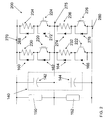
- FIG.1 is a circuit diagram according to an embodiment of the present invention.
- Circuit 100 is shown including a first switch 120 serially connected to a first discharge resistor 130 and a second switch 122 serially connected to a second discharge resistor 132.
- First switch 120 and first discharge resistor 130 are connected to a positive DC bus 170.
- Second switch 122 and second discharge resistor 132 are connected to a negative DC bus 180.
- Circuit 100 also includes a capacitor bank 140 for storing a positive DC voltage and a negative DC voltage.
- Capacitor bank 140 includes a first capacitor 142 (including positive DC voltage) in parallel with first switch 120 and first discharge resistor 130.
- Capacitor bank 140 also includes a second capacitor 144 (including negative DC voltage) in parallel with second switch 122 and second discharge resistor 132.
- the elements shown as switches, discharge resistors, and capacitors can be built up of smaller devices operated either in parallel or in series to perform a net function of a single larger switch, discharge resistor, or capacitor with higher voltage and/or current rating than the individual components.
- First switch 120 and second switch 122 are shown as insulated gate bipolar transistors (IGBT's). However, those skilled in the art will recognize that any now known, or later developed, switching devices may be used in place of the IGBT's.
- first switch 120 and second switch 122 may also include gate turn-off thyristors (GTO's), integrated gate-commutated thryistors (IGCT's), injection enhanced gate transistors (IEGT's), bipolar transistors, MOSFET's, mos-controlled thyristors (MCT's), and possibly forced commutated silicon-controlled rectifiers (SCR's).
- GTO's gate turn-off thyristors
- IGCT's integrated gate-commutated thryistors
- IEGT's injection enhanced gate transistors
- MOSFET's MOSFET's
- MCT's mos-controlled thyristors
- SCR's possibly forced commutated silicon-controlled rectifiers
- Circuit 100 may include at least one sensing unit, such as sensing unit 150 and sensing unit 152, configured to measure a voltage across first capacitor 142 and second capacitor 144, respectively.
- sensing unit 150 senses an overvoltage across first capacitor 142
- first switch 120 operates, independently from second switch 122, to discharge the positive DC voltage.
- sensing unit 152 senses there is an overvoltage across second capacitor 144
- second switch 122 operates, independently from first switch 120, to discharge the negative DC voltage.
- both sensing units 150, 152 sense there is an overvoltage across first capacitor 142 and second capacitor 144
- first switch 120 and second switch 122 may, independently and simultaneously, operate to discharge the positive DC voltage and the negative DC voltage.
- Circuit 200 may include (in addition to those features disclosed above with respect to FIG.
- circuit 200 includes third switch 224 serially connected to a third discharge resistor 234.
- Third switch 224 and third discharge resistor 234 are connected to positive DC bus 270 and in parallel with first switch 220 and first discharge resistor 230.
- Circuit 200 also includes a fourth switch 226 and a fourth discharge resistor 236.
- Fourth switch 226 and fourth discharge resistor 236 are connected to negative DC bus 280 and in parallel with second switch 222 and second discharge resistor 232.
- FIG. 2 only illustrates circuit 200 to include third switch 224 with third discharge resistor 234 and fourth switch 226 with fourth discharge resistor 236, circuit 200 may include a plurality of additional switches and a plurality of additional discharge resistors that operate independently.
- circuit 100 may include a plurality of diodes 160, 162, 164, 166.
- circuit 200 may further include a plurality of diodes 268, 272, 274, and 276.
- the plurality of diodes may be either normally included in a package as part of a commercially available power device or to control any parasitic effects of the power circuit when the switches turn off.
- the plurality of diodes 160, 162, 164, 166, 268, 272, 274, and 276 may be connected in parallel to discharge resistors 230, 232, 234, and 236 and in parallel to switches 220, 222, 224, and 226.
- an alternative embodiment may include only the plurality of diodes 160, 164, 268, and 274 connected in parallel to discharge resistors 230, 232, 234, and 236.
- energy converter 300 is a 3-level converter bridge that includes three series of four IGBT's, with each IGBT in parallel with a diode.
- 3-level converter bridge 300 is connected to positive DC bus 170, 270, neutral DC bus 175, 275, and negative DC bus 180, 280.
- the positive DC bus 170, 270, neutral DC bus 175, 275, and negative DC bus 180, 280 of energy converter 300 are the same as positive DC bus 170, 270, neutral DC bus 175, 275, and negative DC bus 180, 280 of circuit 100, 200.
- Energy converter 300 includes input terminals 310 to connect to a generator 50 ( FIG. 4 ) or a transformer 400 ( FIG. 4 ).
- first discharge resistor 130 and second discharge resistor 132 may be turned on control the voltage until normal grid control is obtained.
- a grid fault may also cause the positive DC voltage and the negative DC voltage to become imbalanced.
- a 3 level bridge converter requires that these two voltages remain balanced.
- First discharge resistor 130 or second discharge resistor 132 may be turned on to reduce the imbalance between the positive DC voltage or the negative DC voltage. Also, if certain power devices in a 3-level converter shorted, for example, the inner diodes 396 or inner IGBT's 394 or diodes 390 connected to neutral DC bus 175 ( FIG. 3 ), an overvoltage, known to those skilled in the art as a "voltage doubler" may occur that will cause either first capacitor 142 or second capacitor 144 to charge to approximately twice the normal operating value. First discharge resistor 130 or second discharge resistor 132 may be turned on to control the overvoltage.
- Wind power unit includes at least one wind turbine 10 that includes a generator 50.
- Wind power unit also includes energy converter 300, such as a 3-level converter ( FIG. 3 ) on the line side and the generator side.
- a transformer 400 is configured to transfer electrical energy from energy converter 300 to the electrical grid.
Landscapes
- Engineering & Computer Science (AREA)
- Power Engineering (AREA)
- Control Of Eletrric Generators (AREA)
- Dc-Dc Converters (AREA)
- Inverter Devices (AREA)
Abstract
Description
- The subject matter disclosed herein relates generally to renewable energy and more particularly to a circuit for use with an energy converter used with a renewable energy-based power unit.
- Wind turbines are one type of renewable energy-based power unit that competes with traditional forms of electric power generation. As a result, wind turbines depend on cost effective, reliable as well as safe means to capture wind energy and convert it to electrical energy that is suitable for delivery miles away. In operation, wind turbines have multiple rotating blades connected to a rotor shaft that are turned by the wind. The rotation of the blades by the wind spins the rotor shaft to generate a rotational torque or force that drives one or more generators to convert mechanical energy to electrical energy. The electrical energy generated by the generator is distributed down through the tower to a utility grid via a transformer.
- Generally, a medium voltage is used to collect electric power from wind turbines in a typical wind power generation application. An energy converter is used on the generator side or the line side, or both. A 3-level bridge is typically used as a power converter in medium voltage systems. A product requirement for the 3-level bridge converter is that the positive direct current (DC) bus voltage and the negative DC bus voltage remain the same, so that the neutral DC bus is balanced. Furthermore, the positive DC bus voltage and the negative DC bus voltage must be constrained to a maximum operating voltage. If a grid fault occurs, control of neutral DC bus can be temporarily restricted. Also, during a grid fault, or during the recovery after a grid fault, the DC bus voltage may overshoot and exceed the maximum peak operating voltage. Additionally, if a grid fault occurs, net energy can flow in the positive to negative DC buses that must be dissipated.
- Various solutions for dissipating regenerative energy during a grid fault and controlling the DC bus voltages with a circuit are disclosed. In one embodiment, the circuit includes: a first switch serially connected to a first discharge resistor, the first switch and the first discharge resistor connected to a positive DC bus; a second switch serially connected to a second discharge resistor, the second switch and the second discharge resistor connected to a negative DC bus; and a capacitor bank for storing a positive DC voltage and a negative DC voltage, the capacitor bank including a first capacitor in parallel with the first switch and the first discharge resistor, and a second capacitor in parallel with the second switch and the second discharge resistor, wherein the first switch operates independently from the second switch to discharge the positive DC voltage through the first discharge resistor and the second switch operates independently from the first switch to discharge the negative DC voltage through the second discharge resistor.
- A first aspect of the invention provides a circuit, comprising: a first switch serially connected to a first discharge resistor, the first switch and the first discharge resistor connected to a positive DC bus; a second switch serially connected to a second discharge resistor, the second switch and the second discharge resistor connected to a negative DC bus; and a capacitor bank for storing a positive DC voltage and a negative DC voltage, the capacitor bank including a first capacitor in parallel with the first switch and the first discharge resistor, and a second capacitor in parallel with the second switch and the second discharge resistor, wherein the first switch operates independently from the second switch to discharge the positive DC voltage through the first discharge resistor and the second switch operates independently from the first switch to discharge the negative DC voltage through the second discharge resistor.
- A second aspect of the invention provides a power unit, comprising: at least one energy converter; a transformer configured to transfer electrical energy from the at least one energy converter to an electrical grid; and a circuit coupled to the at least one energy converter, the circuit comprising: a first switch serially connected to a first discharge resistor, the first switch and the first discharge resistor connected to a positive DC bus; a second switch serially connected to a second discharge resistor, the second switch and the second discharge resistor connected to a negative DC bus; and a capacitor bank for storing a positive DC voltage and a negative DC voltage, the capacitor bank including a first capacitor in parallel with the first switch and the first discharge resistor, and a second capacitor in parallel with the second switch and the second discharge resistor, wherein the first switch operates independently from the second switch to discharge the positive DC voltage through the first discharge resistor and the second switch operates independently of the first switch to discharge the negative DC voltage through the second discharge resistor.
- A third aspect of the invention provides a wind power unit, comprising: at least one wind turbine that includes a generator; at least one energy converter coupled to the generator of the at least one wind turbine; a transformer configured to transfer electrical energy from the at least one energy converter to an electrical grid; and a circuit coupled to the at least one energy converter, the circuit comprising: a first switch serially connected to a first discharge resistor, the first switch and the first discharge resistor connected to a positive DC bus; a second switch serially connected to a second discharge resistor, the second switch and the second discharge resistor connected to a negative DC bus; and a capacitor bank for storing a positive DC voltage and a negative DC voltage, the capacitor bank including a first capacitor in parallel with the first switch and the first discharge resistor, and a second capacitor in parallel with the second switch and the second discharge resistor, wherein the first switch operates independently of the second switch to discharge the positive DC voltage through the first discharge resistor and the second switch operates independently of the first switch to discharge the negative DC voltage through the second discharge resistor.
- Various features of this invention will be more readily understood from the following detailed description of the various aspects of the invention taken in conjunction with the accompanying drawings that depict various embodiments of the invention, in which:
-
FIG. 1 shows a circuit diagram according to an embodiment of the present invention. -
FIG. 2 shows a circuit diagram according to an embodiment of the present invention. -
FIG. 3 shows a circuit diagram of an energy converter according to an embodiment of the present invention. -
FIG. 4 shows a schematic illustration of a wind power unit according to an embodiment of the present invention. - It is noted that the drawings of the invention are not necessarily to scale. The drawings are intended to depict only typical aspects of the invention, and therefore should not be considered as limiting the scope of the invention. In the drawings, like numbering represents like elements between the drawings.
- As indicated above, certain aspects of the invention provide for dissipating regenerative energy and controlling the DC bus voltages during a grid fault. Although the various embodiments of the present invention described herein are directed to using a circuit with a wind turbine, embodiments of the present invention have a wider application of use than with a wind power unit. In particular, various embodiments of the present invention are suitable for any power generation unit such as for example a renewable energy-based power unit. An illustrative, but non-exhaustive list of renewable energy-based power units that may be suited for use with the present invention may include solar, battery energy storage systems, water, geothermal, etc. Those skilled in the art would be able to apply the principals of various embodiments of the present invention to the energy converter used with each of these renewable energy-based power units and the transformer used to distribute the energy to the electrical grid.
- Referring to the drawings,
FIG.1 is a circuit diagram according to an embodiment of the present invention.Circuit 100 is shown including afirst switch 120 serially connected to afirst discharge resistor 130 and asecond switch 122 serially connected to asecond discharge resistor 132.First switch 120 andfirst discharge resistor 130 are connected to apositive DC bus 170.Second switch 122 andsecond discharge resistor 132 are connected to anegative DC bus 180.Circuit 100 also includes acapacitor bank 140 for storing a positive DC voltage and a negative DC voltage.Capacitor bank 140 includes a first capacitor 142 (including positive DC voltage) in parallel withfirst switch 120 andfirst discharge resistor 130.Capacitor bank 140 also includes a second capacitor 144 (including negative DC voltage) in parallel withsecond switch 122 andsecond discharge resistor 132. The elements shown as switches, discharge resistors, and capacitors can be built up of smaller devices operated either in parallel or in series to perform a net function of a single larger switch, discharge resistor, or capacitor with higher voltage and/or current rating than the individual components. -
First switch 120 andsecond switch 122 are shown as insulated gate bipolar transistors (IGBT's). However, those skilled in the art will recognize that any now known, or later developed, switching devices may be used in place of the IGBT's. For example,first switch 120 andsecond switch 122 may also include gate turn-off thyristors (GTO's), integrated gate-commutated thryistors (IGCT's), injection enhanced gate transistors (IEGT's), bipolar transistors, MOSFET's, mos-controlled thyristors (MCT's), and possibly forced commutated silicon-controlled rectifiers (SCR's). -
Circuit 100 may include at least one sensing unit, such assensing unit 150 andsensing unit 152, configured to measure a voltage acrossfirst capacitor 142 andsecond capacitor 144, respectively. During operation ofcircuit 100, ifsensing unit 150 senses an overvoltage acrossfirst capacitor 142,first switch 120 operates, independently fromsecond switch 122, to discharge the positive DC voltage. Conversely, ifsensing unit 152 senses there is an overvoltage acrosssecond capacitor 144,second switch 122 operates, independently fromfirst switch 120, to discharge the negative DC voltage. Furthermore, if bothsensing units first capacitor 142 andsecond capacitor 144,first switch 120 andsecond switch 122 may, independently and simultaneously, operate to discharge the positive DC voltage and the negative DC voltage. Alternatively, ifsensing units switch capacitor switches switch FIG. 2 , an alternative embodiment of acircuit 200 is shown.Circuit 200 may include (in addition to those features disclosed above with respect toFIG. 1 ) a plurality of additional switches and a plurality of additional discharge resistors connected to thepositive DC bus 270 and thenegative DC bus 280. This may allow for the ability to dissipate more power or to control the dissipated power more smoothly. For example, as shown inFIG. 2 ,circuit 200 includesthird switch 224 serially connected to athird discharge resistor 234.Third switch 224 andthird discharge resistor 234 are connected topositive DC bus 270 and in parallel withfirst switch 220 andfirst discharge resistor 230.Circuit 200 also includes afourth switch 226 and afourth discharge resistor 236.Fourth switch 226 andfourth discharge resistor 236 are connected tonegative DC bus 280 and in parallel withsecond switch 222 andsecond discharge resistor 232. AlthoughFIG. 2 only illustratescircuit 200 to includethird switch 224 withthird discharge resistor 234 andfourth switch 226 withfourth discharge resistor 236,circuit 200 may include a plurality of additional switches and a plurality of additional discharge resistors that operate independently. - Referring now to
FIG. 1 ,circuit 100 may include a plurality ofdiodes FIG. 2 ,circuit 200 may further include a plurality ofdiodes diodes discharge resistors switches diodes discharge resistors - Referring now to
FIG. 3 , a circuit diagram of anenergy converter 300 for use withcircuit 100, 200 (FIGS. 1 and2 ) according to an embodiment of the present invention is shown. As shown,energy converter 300 is a 3-level converter bridge that includes three series of four IGBT's, with each IGBT in parallel with a diode. 3-level converter bridge 300 is connected topositive DC bus neutral DC bus negative DC bus positive DC bus neutral DC bus negative DC bus energy converter 300 are the same aspositive DC bus neutral DC bus negative DC bus circuit Energy converter 300 includesinput terminals 310 to connect to a generator 50 (FIG. 4 ) or a transformer 400 (FIG. 4 ). - Examples of situations in which an overvoltage may occur are now discussed. One example is that, during a grid fault, energy may still continue to be created by the generator, but will not flow to the electrical grid. In this case, this energy is dissipated through both
first discharge resistor 130 andsecond discharge resistor 132. Another example is, during a grid fault or recovery after a grid fault, the DC bus voltage may spike.First discharge resistor 130 and/orsecond discharge resistor 132 may be turned on control the voltage until normal grid control is obtained. A grid fault may also cause the positive DC voltage and the negative DC voltage to become imbalanced. However, for proper operation, a 3 level bridge converter requires that these two voltages remain balanced.First discharge resistor 130 orsecond discharge resistor 132 may be turned on to reduce the imbalance between the positive DC voltage or the negative DC voltage. Also, if certain power devices in a 3-level converter shorted, for example, theinner diodes 396 or inner IGBT's 394 ordiodes 390 connected to neutral DC bus 175 (FIG. 3 ), an overvoltage, known to those skilled in the art as a "voltage doubler" may occur that will cause eitherfirst capacitor 142 orsecond capacitor 144 to charge to approximately twice the normal operating value.First discharge resistor 130 orsecond discharge resistor 132 may be turned on to control the overvoltage. - Referring now to
FIG. 4 , a schematic illustration of a wind power unit according to an embodiment of the present invention is shown. Wind power unit includes at least onewind turbine 10 that includes agenerator 50. Wind power unit also includesenergy converter 300, such as a 3-level converter (FIG. 3 ) on the line side and the generator side. Atransformer 400 is configured to transfer electrical energy fromenergy converter 300 to the electrical grid. - The terminology used herein is for the purpose of describing particular embodiments only and is not intended to be limiting of the disclosure. As used herein, the singular forms "a", "an" and "the" are intended to include the plural forms as well, unless the context clearly indicates otherwise. It will be further understood that the terms "comprises" and/or "comprising," when used in this specification, specify the presence of stated features, integers, steps, operations, elements, and/or components, but do not preclude the presence or addition of one or more other features, integers, steps, operations, elements, components, and/or groups thereof.
- This written description uses examples to disclose the invention, including the preferred mode, and also to enable any person skilled in the art to practice the invention, including making and using any devices or systems and performing any incorporated methods. The patentable scope of the invention is defined by the claims, and may include other examples that occur to those skilled in the art. Such other examples are intended to be within the scope of the claims if they have structural elements that do not differ from the literal language of the claims, or if they include equivalent structural elements with insubstantial differences from the literal languages of the claims.
- Various aspects and embodiments of the present invention are defined in the following numbered clauses:
- 1. A circuit, comprising:
- a first switch serially connected to a first discharge resistor, the first switch and the first discharge resistor connected to a positive direct current (DC) bus;
- a second switch serially connected to a second discharge resistor, the second switch and the second discharge resistor connected to a negative DC bus; and
- a capacitor bank for storing a positive DC voltage and a negative DC voltage, the capacitor bank including a first capacitor in parallel with the first switch and the first discharge resistor, and a second capacitor in parallel with the second switch and the second discharge resistor,
- wherein the first switch operates independently from the second switch to discharge the positive DC voltage through the first discharge resistor and the second switch operates independently from the first switch to discharge the negative DC voltage through the second discharge resistor.
- 2. The circuit of
clause 1, further comprising at least one sensing unit configured to measure a voltage across the first capacitor and the second capacitor and sense an overvoltage, such that, in response to the overvoltage across the first capacitor, the first switch operates, independently from the second switch, to discharge the positive DC voltage. - 3. The circuit of any preceding clause, further comprising at least one sensing unit configured to measure a voltage across the first capacitor and the second capacitor and sense an overvoltage, such that, in response to the overvoltage across the second capacitor, the second switch operates, independently of the first switch, to discharge the negative DC voltage.
- 4. The circuit of any preceding clause, further comprising a plurality of additional switches and a plurality of additional discharge resistors, each additional switch serially connected to an additional discharge resistor, each additional switch and each additional discharge resistor connected to the positive DC bus, and in parallel with the first switch and the first discharge resistor.
- 5. The circuit of any preceding clause, further comprising a plurality of additional switches and a plurality of additional discharge resistors, each additional switch serially connected to an additional discharge resistor, each additional switch and each additional discharge resistor connected to the negative DC bus, and in parallel with the second switch and the second discharge resistor.
- 6. The circuit of any preceding clause, further comprising a plurality of diodes, wherein each diode is connected in parallel to each switch and/or each discharge resistor.
- 7. A power unit, comprising:
- at least one energy converter;
- a transformer configured to transfer electrical energy from the at least one energy converter to an electrical grid; and
- a circuit coupled to the at least one energy converter, the circuit comprising:
- a first switch serially connected to a first discharge resistor, the first switch and the first discharge resistor connected to a positive direct current (DC) bus;
- a second switch serially connected to a second discharge resistor, the second switch and the second discharge resistor connected to a negative DC bus; and
- a capacitor bank for storing a positive DC voltage and a negative DC voltage, the capacitor bank including a first capacitor in parallel with the first switch and the first discharge resistor, and a second capacitor in parallel with the second switch and the second discharge resistor,
- wherein the first switch operates independently from the second switch to discharge the positive DC voltage through the first discharge resistor and the second switch operates independently of the first switch to discharge the negative DC voltage through the second discharge resistor.
- 8. The power unit of any preceding clause, wherein the circuit further comprises at least one sensing unit configured to measure a voltage across the first capacitor and the second capacitor and sense an overvoltage, such that, in response to the overvoltage across the first capacitor, the first switch operates, independently of the second switch, to discharge the positive DC voltage.
- 9. The power unit of any preceding clause, wherein the circuit further comprises at least one sensing unit configured to measure a voltage across the first capacitor and the second capacitor and sense an overvoltage, such that, in response to the overvoltage across the second capacitor, the second switch operates, independently of the first switch, to discharge the negative DC voltage.
- 10. The power unit of any preceding clause, wherein the circuit further comprises a plurality of additional switches and a plurality of additional discharge resistors, each additional switch serially connected to an additional discharge resistor, each additional switch and each additional discharge resistor connected to the positive DC bus, and in parallel with the first switch and the first discharge resistor.
- 11. The power unit of any preceding clause, wherein the circuit further comprises a plurality of additional switches and a plurality of additional discharge resistors, each additional switch serially connected to an additional discharge resistor, each additional switch and each additional discharge resistor connected to the negative DC bus, and in parallel with the second switch and the second discharge resistor.
- 12. The power unit of any preceding clause, wherein the circuit further comprises a plurality of diodes, wherein each diode is connected in parallel to each switch and/or each discharge resistor.
- 13. The power unit of any preceding clause, wherein the at least one energy converter is a 3-level converter.
- 14. A wind power unit, comprising:
- at least one wind turbine that includes a generator;
- at least one energy converter coupled to the generator of the at least one wind turbine;
- a transformer configured to transfer electrical energy from the at least one energy converter to an electrical grid; and
- a circuit coupled to the at least one energy converter, the circuit comprising:
- a first switch serially connected to a first discharge resistor, the first switch and the first discharge resistor connected to a positive direct current (DC) bus;
- a second switch serially connected to a second discharge resistor, the second switch and the second discharge resistor connected to a negative DC bus; and
- a capacitor bank for storing a positive DC voltage and a negative DC voltage, the capacitor bank including a first capacitor in parallel with the first switch and the first discharge resistor, and a second capacitor in parallel with the second switch and the second discharge resistor,
- wherein the first switch operates independently of the second switch to discharge the positive DC voltage through the first discharge resistor and the second switch operates independently of the first switch to discharge the negative DC voltage through the second discharge resistor.
- 15. The wind power unit of any preceding clause, wherein the circuit further comprises at least one sensing unit configured to measure a voltage across the first capacitor and the second capacitor and sense an overvoltage, such that, in response to the overvoltage across the first capacitor, the first switch operates, independently of the second switch, to discharge the positive DC voltage.
- 16. The wind power unit of any preceding clause, wherein the circuit further comprises at least one sensing unit configured to measure a voltage across the first capacitor and the second capacitor and sense an overvoltage, such that, in response to the overvoltage across the second capacitor, the second switch operates, independently of the first switch, to discharge the negative DC voltage.
- 17. The wind power unit of any preceding clause, wherein the circuit further comprises a plurality of additional switches and a plurality of additional discharge resistors, each additional switch serially connected to an additional discharge resistor, each additional switch and each additional discharge resistor connected to the positive DC bus, and in parallel with the first switch and the first discharge resistor.
- 18. The wind power unit of any preceding clause, wherein the circuit further comprises a plurality of additional switches and a plurality of additional discharge resistors, each additional switch serially connected to an additional discharge resistor, each additional switch and each additional discharge resistor connected to the negative DC bus, and in parallel with the second switch and the second discharge resistor.
- 19. The wind power unit of any preceding clause, wherein the circuit further comprises a plurality of diodes, wherein each diode is connected in parallel to each switch and/or each discharge resistor.
- 20. The wind power unit of any preceding clause, wherein the at least one energy converter is a 3-level converter.
Claims (10)
- A circuit (100, 200), comprising:a first switch (120, 220) serially connected to a first discharge resistor (130, 230), the first switch (120, 220) and the first discharge resistor (130, 230) connected to a positive direct current (DC) bus (170, 270);a second switch (122, 222) serially connected to a second discharge resistor (132, 232), the second switch (122, 222) and the second discharge resistor (132, 232) connected to a negative DC bus (180, 280); anda capacitor bank (140) for storing a positive DC voltage and a negative DC voltage, the capacitor bank (140) including a first capacitor (142) in parallel with the first switch (122, 222) and the first discharge resistor (130, 230), and a second capacitor (144) in parallel with the second switch (122, 222) and the second discharge resistor (132, 232),wherein the first switch (120, 220) operates independently from the second switch (122, 222) to discharge the positive DC voltage through the first discharge resistor (130, 230) and the second switch (122, 222) operates independently from the first switch (120, 220) to discharge the negative DC voltage through the second discharge resistor (132, 232).
- The circuit (100, 200) of claim 1, further comprising at least one sensing unit (150) configured to measure a voltage across the first capacitor (142) and the second capacitor (144) and sense an overvoltage, such that, in response to the overvoltage across the first capacitor (142), the first switch (120, 220) operates, independently from the second switch (122, 222), to discharge the positive DC voltage.
- The circuit (100, 200) of any preceding claim, further comprising at least one sensing unit (152) configured to measure a voltage across the first capacitor (142) and the second capacitor (144) and sense an overvoltage, such that, in response to the overvoltage across the second capacitor (144), the second switch (122, 222) operates, independently of the first switch (120, 220), to discharge the negative DC voltage.
- The circuit (100, 200) of any preceding claim, further comprising a plurality of additional switches (224) and a plurality of additional discharge resistors (234), each additional switch (224) serially connected to an additional discharge resistor (234), each additional switch (224) and each additional discharge resistor (234) connected to the positive DC bus (170, 270), and in parallel with the first switch (120, 220) and the first discharge resistor (130, 230).
- The circuit (100, 200) of any preceding claim, further comprising a plurality of additional switches (226) and a plurality of additional discharge resistors (236), each additional switch (226) serially connected to an additional discharge resistor (236), each additional switch (226) and each additional discharge resistor (236) connected to the negative DC bus (180, 280), and in parallel with the second switch (122, 222) and the second discharge resistor (132, 232).
- The circuit (100, 200) of any preceding claim, further comprising a plurality of diodes (160, 162, 164, 166 268, 272, 274, 276), wherein each diode (160, 162, 164, 166 268, 272, 274, 276) is connected in parallel to each switch (120, 122, 220, 222, 224, 226) and/or each discharge resistor (130, 132, 230, 232, 234, 236).
- A power unit, comprising:at least one energy converter (300);a transformer (400) configured to transfer electrical energy from the at least one energy converter (300) to an electrical grid; anda circuit (100, 200) coupled to the at least one energy converter (300), the circuit (100, 200) comprising:a first switch (120, 220) serially connected to a first discharge resistor (130, 230), the first switch (120, 220) and the first discharge resistor (130, 230) connected to a positive direct current (DC) bus (170, 270);a second switch (122, 222) serially connected to a second discharge resistor (132, 232), the second switch (122, 222) and the second discharge resistor (132, 232) connected to a negative DC bus (180, 280); anda capacitor bank (140) for storing a positive DC voltage and a negative DC voltage, the capacitor bank (140) including a first capacitor (142) in parallel with the first switch (120, 220) and the first discharge resistor (130, 230), and a second capacitor (144) in parallel with the second switch (122, 222) and the second discharge resistor (132, 232),wherein the first switch (120, 220) operates independently from the second switch (122, 222) to discharge the positive DC voltage through the first discharge resistor (130, 230) and the second switch (122, 222) operates independently of the first switch (120, 220) to discharge the negative DC voltage through the second discharge resistor (132, 232).
- The power unit of claim 7, wherein the circuit (100, 200) further comprises at least one sensing unit (150) configured to measure a voltage across the first capacitor (142) and the second capacitor (144) and sense an overvoltage, such that, in response to the overvoltage across the first capacitor (142), the first switch (120, 220) operates, independently of the second switch (122, 222), to discharge the positive DC voltage.
- The power unit of claim 7 or claim 8, wherein the circuit (100, 200) further comprises at least one sensing unit (152) configured to measure a voltage across the first capacitor (142) and the second capacitor (144) and sense an overvoltage, such that, in response to the overvoltage across the second capacitor (144), the second switch (122, 222) operates, independently of the first switch (120, 220), to discharge the negative DC voltage.
- A wind power unit, comprising:at least one wind turbine (10) that includes a generator (50);at least one energy converter (300) coupled to the generator (50) of the at least one wind turbine (10);a transformer (400) configured to transfer electrical energy from the at least one energy converter (300) to an electrical grid; anda circuit (100, 200) coupled to the at least one energy converter (300), the circuit (100, 200) comprising:a first switch (120, 220) serially connected to a first discharge resistor (130, 230), the first switch (120, 220) and the first discharge resistor (130, 230) connected to a positive direct current (DC) bus (170, 270);a second switch (122, 222) serially connected to a second discharge resistor (132, 232), the second switch (122, 222) and the second discharge resistor (132, 232) connected to a negative DC bus (180, 280); anda capacitor bank (140) for storing a positive DC voltage and a negative DC voltage, the capacitor bank (140) including a first capacitor (142) in parallel with the first switch (120, 220) and the first discharge resistor (130, 230), and a second capacitor (144) in parallel with the second switch (122, 222) and the second discharge resistor (132, 232),wherein the first switch (120, 220) operates independently of the second switch (122, 222) to discharge the positive DC voltage through the first discharge resistor (130, 230) and the second switch (122, 222) operates independently of the first switch (120, 220) to discharge the negative DC voltage through the second discharge resistor (122, 222).
Applications Claiming Priority (1)
| Application Number | Priority Date | Filing Date | Title |
|---|---|---|---|
| US12/699,606 US8120885B2 (en) | 2010-02-03 | 2010-02-03 | Circuit for use with energy converter |
Publications (2)
| Publication Number | Publication Date |
|---|---|
| EP2355296A1 true EP2355296A1 (en) | 2011-08-10 |
| EP2355296B1 EP2355296B1 (en) | 2022-06-08 |
Family
ID=43836840
Family Applications (1)
| Application Number | Title | Priority Date | Filing Date |
|---|---|---|---|
| EP11152181.1A Active EP2355296B1 (en) | 2010-02-03 | 2011-01-26 | Circuit for use with energy converter |
Country Status (5)
| Country | Link |
|---|---|
| US (1) | US8120885B2 (en) |
| EP (1) | EP2355296B1 (en) |
| CN (1) | CN102142691B (en) |
| DK (1) | DK2355296T3 (en) |
| ES (1) | ES2925012T3 (en) |
Families Citing this family (14)
| Publication number | Priority date | Publication date | Assignee | Title |
|---|---|---|---|---|
| US8630077B2 (en) * | 2011-12-22 | 2014-01-14 | Sunpower Corporation | Circuits and methods for limiting open circuit voltage of photovoltaic strings |
| US9184584B2 (en) | 2011-12-29 | 2015-11-10 | General Electric Company | Device and system for reducing overvoltage damange |
| EP2621070A1 (en) * | 2012-01-26 | 2013-07-31 | Siemens Aktiengesellschaft | Method and arrangement for operating a wind turbine converter |
| US9684328B2 (en) | 2012-12-21 | 2017-06-20 | General Electric Company | Systems and methods for overvoltage protection of power converters |
| WO2015055211A1 (en) * | 2013-10-18 | 2015-04-23 | Vestas Wind Systems A/S | Converters for wind turbine generators |
| CN103595221A (en) * | 2013-10-24 | 2014-02-19 | 张家港智电西威变流技术有限公司 | Control power source device of voltage source current transforming module |
| DK178820B1 (en) * | 2014-11-04 | 2017-02-27 | Kk Wind Solutions As | Monitoring unit for a power converter |
| CN104391535B (en) * | 2014-11-21 | 2016-04-20 | 常熟开关制造有限公司(原常熟开关厂) | A kind of dc-link capacitance method for equalizing voltage and device |
| AU2015364718B2 (en) * | 2014-12-16 | 2019-11-28 | Marici Holdings The Netherlands B.V. | Energy panel arrangement power dissipation |
| JP6919348B2 (en) * | 2017-06-07 | 2021-08-18 | 株式会社デンソー | Power converter |
| US10615600B1 (en) * | 2019-01-10 | 2020-04-07 | Northeast Power Systems, Inc. | Reactive power system in communication with motor starter system |
| CN113410998A (en) * | 2021-07-22 | 2021-09-17 | 上海电气风电集团股份有限公司 | Converter and wind generating set with same |
| JP7599802B2 (en) * | 2021-08-16 | 2024-12-16 | 株式会社Tmeic | Power Conversion Equipment |
| CN116231658B (en) * | 2022-12-29 | 2024-12-06 | 中国华能集团清洁能源技术研究院有限公司 | Novel hybrid direct current unloading device and unloading method |
Citations (3)
| Publication number | Priority date | Publication date | Assignee | Title |
|---|---|---|---|---|
| EP0250719A2 (en) * | 1986-06-23 | 1988-01-07 | Siemens Aktiengesellschaft | Process for the low-loss operation of a balancing and brake adjusting device for an inverter having a high intermediate circuit voltage |
| EP1443634A2 (en) * | 2003-01-24 | 2004-08-04 | Toshiba International Corporation | Inverter drive system having changeable configurations |
| WO2006069569A1 (en) * | 2004-12-28 | 2006-07-06 | Vestas Wind Systems A/S | Method of controlling a wind turbine connected to an electric utility grid |
Family Cites Families (11)
| Publication number | Priority date | Publication date | Assignee | Title |
|---|---|---|---|---|
| US5426579A (en) * | 1993-07-28 | 1995-06-20 | Best Power Technology, Incorporated | Method and apparatus for stabilizing AC power supply systems connected to power factor correcting loads |
| CN100356683C (en) | 2002-01-29 | 2007-12-19 | 威斯塔斯风力系统公开有限公司 | Circuit to be used in a wind power plant |
| AU2003251306A1 (en) * | 2002-05-20 | 2003-12-12 | Good Ideas Llc | Ultracapacitor balancing circuit |
| ES2392683T3 (en) | 2002-11-01 | 2012-12-12 | Vestas Wind Systems A/S | Circuit layout for use in a variable speed wind turbine system comprising a double feed induction generator and a reversible converter |
| ATE442701T1 (en) | 2003-02-07 | 2009-09-15 | Vestas Wind Sys As | CONTROL METHOD FOR A WIND TURBINE GENERATOR CONNECTED TO A HIGH VOLTAGE GRID DURING A GRID FAILURE AND DEVICE FOR IMPLEMENTING SUCH METHOD |
| EP1625457A4 (en) | 2003-05-02 | 2015-04-22 | Xantrex Technology Inc | Control system for doubly fed induction generator |
| PL1652586T5 (en) * | 2004-10-26 | 2016-08-31 | Smidth As F L | Pulse generating system for electrostatic precipitator |
| US7239036B2 (en) | 2005-07-29 | 2007-07-03 | General Electric Company | System and method for power control in wind turbines |
| ES2730073T3 (en) | 2007-03-30 | 2019-11-08 | Nordex Energy Spain S A | DC voltage regulator |
| US8044527B2 (en) | 2007-09-26 | 2011-10-25 | General Electric Company | Electric power generation with magnetically geared machine |
| US8427010B2 (en) * | 2009-05-29 | 2013-04-23 | General Electric Company | DC-to-AC power conversion system and method |
-
2010
- 2010-02-03 US US12/699,606 patent/US8120885B2/en active Active
-
2011
- 2011-01-26 EP EP11152181.1A patent/EP2355296B1/en active Active
- 2011-01-26 ES ES11152181T patent/ES2925012T3/en active Active
- 2011-01-26 DK DK11152181.1T patent/DK2355296T3/en active
- 2011-01-26 CN CN201110037534.8A patent/CN102142691B/en active Active
Patent Citations (3)
| Publication number | Priority date | Publication date | Assignee | Title |
|---|---|---|---|---|
| EP0250719A2 (en) * | 1986-06-23 | 1988-01-07 | Siemens Aktiengesellschaft | Process for the low-loss operation of a balancing and brake adjusting device for an inverter having a high intermediate circuit voltage |
| EP1443634A2 (en) * | 2003-01-24 | 2004-08-04 | Toshiba International Corporation | Inverter drive system having changeable configurations |
| WO2006069569A1 (en) * | 2004-12-28 | 2006-07-06 | Vestas Wind Systems A/S | Method of controlling a wind turbine connected to an electric utility grid |
Also Published As
| Publication number | Publication date |
|---|---|
| US8120885B2 (en) | 2012-02-21 |
| ES2925012T3 (en) | 2022-10-13 |
| CN102142691B (en) | 2016-05-18 |
| CN102142691A (en) | 2011-08-03 |
| EP2355296B1 (en) | 2022-06-08 |
| DK2355296T3 (en) | 2022-09-12 |
| US20110141637A1 (en) | 2011-06-16 |
Similar Documents
| Publication | Publication Date | Title |
|---|---|---|
| US8120885B2 (en) | Circuit for use with energy converter | |
| Yang et al. | A series-dynamic-resistor-based converter protection scheme for doubly-fed induction generator during various fault conditions | |
| US8922173B2 (en) | DC chopper and DC chopping method for doubly fed induction generator system | |
| CN104769804B (en) | Turbine-based energy generation system with DC output | |
| EP2566042B2 (en) | System and method to control a electrical generator | |
| EP3629440B1 (en) | System and method for controlling uninterruptible power supply of electrical power systems | |
| US20120133343A1 (en) | Wind turbine having a high-voltage ride through (hvrt) mode | |
| CN101609992A (en) | Converter for low-voltage traversing double-fed wind driven generator | |
| US9088150B2 (en) | Overvoltage clipping device for a wind turbine and method | |
| US9455568B2 (en) | Energy storage system for renewable energy source | |
| EP4187766A1 (en) | System and method for detection of switching device failure conditions in a multi-level power converter | |
| US11843325B2 (en) | Crowbar module for an active neutral point clamped power conversion assembly | |
| Garcés et al. | High frequency wind energy conversion from the ocean | |
| CN108023470B (en) | Crowbar protection circuit for double-fed power generation system | |
| Xu et al. | Design, development and test of a novel DC chopper for offshore wind power HVDC system | |
| Sarafianos | Modular Multilevel Converter Cell Construction | |
| Hein et al. | Reduction of negative effects of a short circuit through improved converter topology for wind energy applications | |
| CN213151921U (en) | Crowbar circuit, device and motor | |
| CN201846092U (en) | High-power direct-drive wind power generating current transformer low-voltage ride-through circuit | |
| Chen et al. | Experimental and simulation comparison for timer action crowbar of doubly-fed induction generator | |
| KR101748604B1 (en) | Apparatus and method for operating converters of wind turbine system | |
| KR101838181B1 (en) | Apparatus and method for operating switching module of wind turbine system |
Legal Events
| Date | Code | Title | Description |
|---|---|---|---|
| PUAI | Public reference made under article 153(3) epc to a published international application that has entered the european phase |
Free format text: ORIGINAL CODE: 0009012 |
|
| AK | Designated contracting states |
Kind code of ref document: A1 Designated state(s): AL AT BE BG CH CY CZ DE DK EE ES FI FR GB GR HR HU IE IS IT LI LT LU LV MC MK MT NL NO PL PT RO RS SE SI SK SM TR |
|
| AX | Request for extension of the european patent |
Extension state: BA ME |
|
| 17P | Request for examination filed |
Effective date: 20120210 |
|
| 17Q | First examination report despatched |
Effective date: 20160308 |
|
| APBK | Appeal reference recorded |
Free format text: ORIGINAL CODE: EPIDOSNREFNE |
|
| APBN | Date of receipt of notice of appeal recorded |
Free format text: ORIGINAL CODE: EPIDOSNNOA2E |
|
| APBR | Date of receipt of statement of grounds of appeal recorded |
Free format text: ORIGINAL CODE: EPIDOSNNOA3E |
|
| APAZ | Date of receipt of statement of grounds of appeal deleted |
Free format text: ORIGINAL CODE: EPIDOSDNOA3E |
|
| APBR | Date of receipt of statement of grounds of appeal recorded |
Free format text: ORIGINAL CODE: EPIDOSNNOA3E |
|
| APAF | Appeal reference modified |
Free format text: ORIGINAL CODE: EPIDOSCREFNE |
|
| APBT | Appeal procedure closed |
Free format text: ORIGINAL CODE: EPIDOSNNOA9E |
|
| GRAP | Despatch of communication of intention to grant a patent |
Free format text: ORIGINAL CODE: EPIDOSNIGR1 |
|
| STAA | Information on the status of an ep patent application or granted ep patent |
Free format text: STATUS: GRANT OF PATENT IS INTENDED |
|
| RIC1 | Information provided on ipc code assigned before grant |
Ipc: H02J 3/46 20060101ALI20211203BHEP Ipc: H02M 7/487 20070101ALI20211203BHEP Ipc: H02M 7/483 20070101ALI20211203BHEP Ipc: H02J 3/38 20060101AFI20211203BHEP |
|
| INTG | Intention to grant announced |
Effective date: 20220104 |
|
| GRAS | Grant fee paid |
Free format text: ORIGINAL CODE: EPIDOSNIGR3 |
|
| GRAA | (expected) grant |
Free format text: ORIGINAL CODE: 0009210 |
|
| STAA | Information on the status of an ep patent application or granted ep patent |
Free format text: STATUS: THE PATENT HAS BEEN GRANTED |
|
| AK | Designated contracting states |
Kind code of ref document: B1 Designated state(s): AL AT BE BG CH CY CZ DE DK EE ES FI FR GB GR HR HU IE IS IT LI LT LU LV MC MK MT NL NO PL PT RO RS SE SI SK SM TR |
|
| REG | Reference to a national code |
Ref country code: GB Ref legal event code: FG4D |
|
| REG | Reference to a national code |
Ref country code: AT Ref legal event code: REF Ref document number: 1497583 Country of ref document: AT Kind code of ref document: T Effective date: 20220615 Ref country code: CH Ref legal event code: EP |
|
| REG | Reference to a national code |
Ref country code: DE Ref legal event code: R096 Ref document number: 602011072970 Country of ref document: DE |
|
| REG | Reference to a national code |
Ref country code: IE Ref legal event code: FG4D |
|
| REG | Reference to a national code |
Ref country code: DK Ref legal event code: T3 Effective date: 20220905 |
|
| REG | Reference to a national code |
Ref country code: LT Ref legal event code: MG9D |
|
| REG | Reference to a national code |
Ref country code: NL Ref legal event code: MP Effective date: 20220608 |
|
| REG | Reference to a national code |
Ref country code: ES Ref legal event code: FG2A Ref document number: 2925012 Country of ref document: ES Kind code of ref document: T3 Effective date: 20221013 |
|
| PG25 | Lapsed in a contracting state [announced via postgrant information from national office to epo] |
Ref country code: SE Free format text: LAPSE BECAUSE OF FAILURE TO SUBMIT A TRANSLATION OF THE DESCRIPTION OR TO PAY THE FEE WITHIN THE PRESCRIBED TIME-LIMIT Effective date: 20220608 Ref country code: NO Free format text: LAPSE BECAUSE OF FAILURE TO SUBMIT A TRANSLATION OF THE DESCRIPTION OR TO PAY THE FEE WITHIN THE PRESCRIBED TIME-LIMIT Effective date: 20220908 Ref country code: LT Free format text: LAPSE BECAUSE OF FAILURE TO SUBMIT A TRANSLATION OF THE DESCRIPTION OR TO PAY THE FEE WITHIN THE PRESCRIBED TIME-LIMIT Effective date: 20220608 Ref country code: HR Free format text: LAPSE BECAUSE OF FAILURE TO SUBMIT A TRANSLATION OF THE DESCRIPTION OR TO PAY THE FEE WITHIN THE PRESCRIBED TIME-LIMIT Effective date: 20220608 Ref country code: GR Free format text: LAPSE BECAUSE OF FAILURE TO SUBMIT A TRANSLATION OF THE DESCRIPTION OR TO PAY THE FEE WITHIN THE PRESCRIBED TIME-LIMIT Effective date: 20220909 Ref country code: FI Free format text: LAPSE BECAUSE OF FAILURE TO SUBMIT A TRANSLATION OF THE DESCRIPTION OR TO PAY THE FEE WITHIN THE PRESCRIBED TIME-LIMIT Effective date: 20220608 Ref country code: BG Free format text: LAPSE BECAUSE OF FAILURE TO SUBMIT A TRANSLATION OF THE DESCRIPTION OR TO PAY THE FEE WITHIN THE PRESCRIBED TIME-LIMIT Effective date: 20220908 |
|
| REG | Reference to a national code |
Ref country code: AT Ref legal event code: MK05 Ref document number: 1497583 Country of ref document: AT Kind code of ref document: T Effective date: 20220608 |
|
| PG25 | Lapsed in a contracting state [announced via postgrant information from national office to epo] |
Ref country code: RS Free format text: LAPSE BECAUSE OF FAILURE TO SUBMIT A TRANSLATION OF THE DESCRIPTION OR TO PAY THE FEE WITHIN THE PRESCRIBED TIME-LIMIT Effective date: 20220608 Ref country code: LV Free format text: LAPSE BECAUSE OF FAILURE TO SUBMIT A TRANSLATION OF THE DESCRIPTION OR TO PAY THE FEE WITHIN THE PRESCRIBED TIME-LIMIT Effective date: 20220608 |
|
| PG25 | Lapsed in a contracting state [announced via postgrant information from national office to epo] |
Ref country code: NL Free format text: LAPSE BECAUSE OF FAILURE TO SUBMIT A TRANSLATION OF THE DESCRIPTION OR TO PAY THE FEE WITHIN THE PRESCRIBED TIME-LIMIT Effective date: 20220608 |
|
| PG25 | Lapsed in a contracting state [announced via postgrant information from national office to epo] |
Ref country code: SM Free format text: LAPSE BECAUSE OF FAILURE TO SUBMIT A TRANSLATION OF THE DESCRIPTION OR TO PAY THE FEE WITHIN THE PRESCRIBED TIME-LIMIT Effective date: 20220608 Ref country code: SK Free format text: LAPSE BECAUSE OF FAILURE TO SUBMIT A TRANSLATION OF THE DESCRIPTION OR TO PAY THE FEE WITHIN THE PRESCRIBED TIME-LIMIT Effective date: 20220608 Ref country code: RO Free format text: LAPSE BECAUSE OF FAILURE TO SUBMIT A TRANSLATION OF THE DESCRIPTION OR TO PAY THE FEE WITHIN THE PRESCRIBED TIME-LIMIT Effective date: 20220608 Ref country code: PT Free format text: LAPSE BECAUSE OF FAILURE TO SUBMIT A TRANSLATION OF THE DESCRIPTION OR TO PAY THE FEE WITHIN THE PRESCRIBED TIME-LIMIT Effective date: 20221010 Ref country code: EE Free format text: LAPSE BECAUSE OF FAILURE TO SUBMIT A TRANSLATION OF THE DESCRIPTION OR TO PAY THE FEE WITHIN THE PRESCRIBED TIME-LIMIT Effective date: 20220608 Ref country code: CZ Free format text: LAPSE BECAUSE OF FAILURE TO SUBMIT A TRANSLATION OF THE DESCRIPTION OR TO PAY THE FEE WITHIN THE PRESCRIBED TIME-LIMIT Effective date: 20220608 Ref country code: AT Free format text: LAPSE BECAUSE OF FAILURE TO SUBMIT A TRANSLATION OF THE DESCRIPTION OR TO PAY THE FEE WITHIN THE PRESCRIBED TIME-LIMIT Effective date: 20220608 |
|
| PG25 | Lapsed in a contracting state [announced via postgrant information from national office to epo] |
Ref country code: PL Free format text: LAPSE BECAUSE OF FAILURE TO SUBMIT A TRANSLATION OF THE DESCRIPTION OR TO PAY THE FEE WITHIN THE PRESCRIBED TIME-LIMIT Effective date: 20220608 Ref country code: IS Free format text: LAPSE BECAUSE OF FAILURE TO SUBMIT A TRANSLATION OF THE DESCRIPTION OR TO PAY THE FEE WITHIN THE PRESCRIBED TIME-LIMIT Effective date: 20221008 |
|
| REG | Reference to a national code |
Ref country code: DE Ref legal event code: R097 Ref document number: 602011072970 Country of ref document: DE |
|
| PG25 | Lapsed in a contracting state [announced via postgrant information from national office to epo] |
Ref country code: AL Free format text: LAPSE BECAUSE OF FAILURE TO SUBMIT A TRANSLATION OF THE DESCRIPTION OR TO PAY THE FEE WITHIN THE PRESCRIBED TIME-LIMIT Effective date: 20220608 |
|
| PLBE | No opposition filed within time limit |
Free format text: ORIGINAL CODE: 0009261 |
|
| STAA | Information on the status of an ep patent application or granted ep patent |
Free format text: STATUS: NO OPPOSITION FILED WITHIN TIME LIMIT |
|
| 26N | No opposition filed |
Effective date: 20230310 |
|
| PG25 | Lapsed in a contracting state [announced via postgrant information from national office to epo] |
Ref country code: SI Free format text: LAPSE BECAUSE OF FAILURE TO SUBMIT A TRANSLATION OF THE DESCRIPTION OR TO PAY THE FEE WITHIN THE PRESCRIBED TIME-LIMIT Effective date: 20220608 |
|
| P01 | Opt-out of the competence of the unified patent court (upc) registered |
Effective date: 20230530 |
|
| REG | Reference to a national code |
Ref country code: CH Ref legal event code: PL |
|
| GBPC | Gb: european patent ceased through non-payment of renewal fee |
Effective date: 20230126 |
|
| PG25 | Lapsed in a contracting state [announced via postgrant information from national office to epo] |
Ref country code: LU Free format text: LAPSE BECAUSE OF NON-PAYMENT OF DUE FEES Effective date: 20230126 |
|
| REG | Reference to a national code |
Ref country code: BE Ref legal event code: MM Effective date: 20230131 |
|
| PG25 | Lapsed in a contracting state [announced via postgrant information from national office to epo] |
Ref country code: LI Free format text: LAPSE BECAUSE OF NON-PAYMENT OF DUE FEES Effective date: 20230131 Ref country code: GB Free format text: LAPSE BECAUSE OF NON-PAYMENT OF DUE FEES Effective date: 20230126 Ref country code: CH Free format text: LAPSE BECAUSE OF NON-PAYMENT OF DUE FEES Effective date: 20230131 |
|
| PG25 | Lapsed in a contracting state [announced via postgrant information from national office to epo] |
Ref country code: FR Free format text: LAPSE BECAUSE OF NON-PAYMENT OF DUE FEES Effective date: 20230131 Ref country code: BE Free format text: LAPSE BECAUSE OF NON-PAYMENT OF DUE FEES Effective date: 20230131 |
|
| REG | Reference to a national code |
Ref country code: DE Ref legal event code: R082 Ref document number: 602011072970 Country of ref document: DE Representative=s name: ZIMMERMANN & PARTNER PATENTANWAELTE MBB, DE Ref country code: DE Ref legal event code: R082 Ref document number: 602011072970 Country of ref document: DE Ref country code: DE Ref legal event code: R081 Ref document number: 602011072970 Country of ref document: DE Owner name: GENERAL ELECTRIC RENOVABLES ESPANA, S.L., ES Free format text: FORMER OWNER: GENERAL ELECTRIC COMPANY, SCHENECTADY, NY, US |
|
| PG25 | Lapsed in a contracting state [announced via postgrant information from national office to epo] |
Ref country code: IT Free format text: LAPSE BECAUSE OF FAILURE TO SUBMIT A TRANSLATION OF THE DESCRIPTION OR TO PAY THE FEE WITHIN THE PRESCRIBED TIME-LIMIT Effective date: 20220608 Ref country code: IE Free format text: LAPSE BECAUSE OF NON-PAYMENT OF DUE FEES Effective date: 20230126 |
|
| REG | Reference to a national code |
Ref country code: DE Ref legal event code: R082 Ref document number: 602011072970 Country of ref document: DE Representative=s name: ZIMMERMANN & PARTNER PATENTANWAELTE MBB, DE |
|
| PG25 | Lapsed in a contracting state [announced via postgrant information from national office to epo] |
Ref country code: MC Free format text: LAPSE BECAUSE OF FAILURE TO SUBMIT A TRANSLATION OF THE DESCRIPTION OR TO PAY THE FEE WITHIN THE PRESCRIBED TIME-LIMIT Effective date: 20220608 |
|
| PG25 | Lapsed in a contracting state [announced via postgrant information from national office to epo] |
Ref country code: MC Free format text: LAPSE BECAUSE OF FAILURE TO SUBMIT A TRANSLATION OF THE DESCRIPTION OR TO PAY THE FEE WITHIN THE PRESCRIBED TIME-LIMIT Effective date: 20220608 |
|
| REG | Reference to a national code |
Ref country code: ES Ref legal event code: PC2A Owner name: GENERAL ELECTRIC RENOVABLES ESPANA S.L. Effective date: 20240722 |
|
| PG25 | Lapsed in a contracting state [announced via postgrant information from national office to epo] |
Ref country code: BG Free format text: LAPSE BECAUSE OF FAILURE TO SUBMIT A TRANSLATION OF THE DESCRIPTION OR TO PAY THE FEE WITHIN THE PRESCRIBED TIME-LIMIT Effective date: 20220608 |
|
| PG25 | Lapsed in a contracting state [announced via postgrant information from national office to epo] |
Ref country code: BG Free format text: LAPSE BECAUSE OF FAILURE TO SUBMIT A TRANSLATION OF THE DESCRIPTION OR TO PAY THE FEE WITHIN THE PRESCRIBED TIME-LIMIT Effective date: 20220608 |
|
| PG25 | Lapsed in a contracting state [announced via postgrant information from national office to epo] |
Ref country code: CY Free format text: LAPSE BECAUSE OF FAILURE TO SUBMIT A TRANSLATION OF THE DESCRIPTION OR TO PAY THE FEE WITHIN THE PRESCRIBED TIME-LIMIT; INVALID AB INITIO Effective date: 20110126 |
|
| PG25 | Lapsed in a contracting state [announced via postgrant information from national office to epo] |
Ref country code: HU Free format text: LAPSE BECAUSE OF FAILURE TO SUBMIT A TRANSLATION OF THE DESCRIPTION OR TO PAY THE FEE WITHIN THE PRESCRIBED TIME-LIMIT; INVALID AB INITIO Effective date: 20110126 |
|
| PG25 | Lapsed in a contracting state [announced via postgrant information from national office to epo] |
Ref country code: TR Free format text: LAPSE BECAUSE OF FAILURE TO SUBMIT A TRANSLATION OF THE DESCRIPTION OR TO PAY THE FEE WITHIN THE PRESCRIBED TIME-LIMIT Effective date: 20220608 |
|
| PGFP | Annual fee paid to national office [announced via postgrant information from national office to epo] |
Ref country code: DK Payment date: 20251217 Year of fee payment: 16 |
|
| PGFP | Annual fee paid to national office [announced via postgrant information from national office to epo] |
Ref country code: ES Payment date: 20260202 Year of fee payment: 16 |
|
| PGFP | Annual fee paid to national office [announced via postgrant information from national office to epo] |
Ref country code: DE Payment date: 20251217 Year of fee payment: 16 |