EP2355247A1 - Extendable rib reflector - Google Patents
Extendable rib reflector Download PDFInfo
- Publication number
- EP2355247A1 EP2355247A1 EP11000783A EP11000783A EP2355247A1 EP 2355247 A1 EP2355247 A1 EP 2355247A1 EP 11000783 A EP11000783 A EP 11000783A EP 11000783 A EP11000783 A EP 11000783A EP 2355247 A1 EP2355247 A1 EP 2355247A1
- Authority
- EP
- European Patent Office
- Prior art keywords
- rib
- ribs
- extendable
- reflector
- centrally located
- Prior art date
- Legal status (The legal status is an assumption and is not a legal conclusion. Google has not performed a legal analysis and makes no representation as to the accuracy of the status listed.)
- Withdrawn
Links
Images






Classifications
-
- H—ELECTRICITY
- H01—ELECTRIC ELEMENTS
- H01Q—ANTENNAS, i.e. RADIO AERIALS
- H01Q15/00—Devices for reflection, refraction, diffraction or polarisation of waves radiated from an antenna, e.g. quasi-optical devices
- H01Q15/14—Reflecting surfaces; Equivalent structures
- H01Q15/16—Reflecting surfaces; Equivalent structures curved in two dimensions [2D], e.g. paraboloidal
- H01Q15/161—Collapsible reflectors
Definitions
- the inventive arrangements relate to compact antenna system structures, and more particularly, to a compact deployable antenna reflector structure.
- Various conventional antenna structures exist that include a reflector for directing energy into a desired pattern.
- One such conventional antenna structure is a radial rib reflector design comprising a plurality of reflector ribs joined together at a common cylindrical shaped hub.
- the reflector ribs provide structural support to a flexible antenna reflector surface attached thereto.
- a plurality of wires or guidelines couple the flexible antenna reflector surface to the reflector ribs.
- the wires or guidelines define and maintain the shape of the flexible antenna reflector surface.
- the radial rib reflector is collapsible so that it can be transitioned from a deployed position to a stowed position. In the deployed position, the radial rib reflector has a generally parabolic shape. In the stowed position, the reflector ribs are folded up against each other. As a result, the antenna reflector has a stowed height approximately equal to the reflector's radius.
- Another conventional antenna structure is a folding rib reflector having a similar design to the radial rib reflector design described above.
- the reflector ribs include a first rib shaft and second rib shaft joined together by a common joint. In the stowed position, the first rib shafts are folded up against the second rib shafts.
- the antenna reflector has a stowed height that is less than the stowed height of the radial rib reflector design.
- the stowed diameter of the folding rib reflector is larger than the stowed diameter of the radial rib reflector design.
- Embodiments of the present invention concern antenna reflectors and methods of deploying the antenna reflectors.
- Each of the antenna reflectors includes extendable ribs coupled to a centrally located hub.
- Each of the extendable ribs includes an inner rib rotatably coupled to the hub.
- Each of the extendable ribs also includes an outer rib slidingly coupled to a respective inner rib.
- the outer rib can be, but is not limited to, a hollow tube or a collar.
- the extendable ribs are rotated from a stowed position in which the extendable ribs are generally aligned with a central axis of the hub, to a rotated position in which the extendable ribs extend in radial directions relative to the central axis.
- Each of the outer ribs is linearly displaced on the inner rib from a proximal position adjacent to the hub to an extended position distal from the hub.
- a flexible antenna reflector surface is supported on a guideline truss structure that is under tension when each of the outer ribs is in its extended position.
- the guideline truss structure includes cords attached at intermediate locations along a length of each outer rib between opposing ends thereof.
- Each of the outer ribs is secured in its extended position with a locking mechanism or a mechanism configured to eliminate a reverse motion of said extended outer rib.
- a shaped reflective surface is illuminated using an antenna feed supportably located in opposed relation with respect to the curved reflective surface.
- the antenna reflector is re-stored to its stowed position by unsecuring the outer ribs, and linearly displacing each of the outer ribs on a respective inner rib from its extended position to its proximal position adjacent to the hub.
- Each of the outer ribs is linearly displaced on the respective inner rib by transforming a rotation induced by at least one motor of the hub to linear motion.
- the rotation is transformed to a linear motion using at least one mechanical component.
- the mechanical component can be selected from the group comprising a worm gear, a pinion gear, a spur gear, a pulley with a driving belt and a drive shaft.
- one or more solar panels are concurrently extended with the rotating and linearly displacing outer ribs.
- the solar panels can be used to charge a battery.
- the battery can supply electrical power to the antenna system inclusive of the motor facilitating the deployment of the antenna reflector.
- FIG. 1 is a perspective view of an exemplary extendable rib reflector in a stowed position.
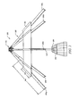
- FIG. 2 is a side view of an exemplary extendable rib reflector having reflector ribs at least partially rotated away from each other.
- FIG. 3 is a perspective side view of an exemplary extendable rib reflector in a fully extended position.
- FIG. 4 is a schematic illustration of an exemplary extendable rib of the extendable rib reflector of FIG. 1 .
- FIG. 5 is a schematic illustration of another exemplary extendable rib that is useful for understanding the present invention.
- FIG. 6 is a schematic illustration of yet another exemplary extendable rib that is useful for understanding the present invention.
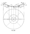
- FIG. 7 is a cross sectional view of an exemplary extendable rib reflector that is useful for understanding a guideline truss structure.
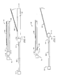
- FIGS. 8A-8E collectively illustrate a deployment sequence for the extendable rib reflector shown in FIG. 7 .
- FIG. 9 is a front perspective view of an exemplary extendable rib reflector antenna that is useful for understanding the present invention.
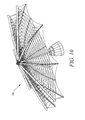
- FIG. 10 is a back perspective view of an exemplary extendable rib reflector antenna that is useful for understanding the present invention.
- exemplary is used herein to mean serving as an example, instance or illustration. Any aspect or design described herein as “exemplary” is not necessarily to be construed as preferred or advantageous over other aspects or designs. Rather, use of the word exemplary is intended to present concepts in a concrete fashion.
- the term “or” is intended to mean an inclusive “or” rather than an exclusive “or”. That is, unless specified otherwise, or clear from context, "X employs A or B” is intended to mean any of the natural inclusive permutations. That is if, X employs A; X employs B; or X employs both A and B, then "X employs A or B" is satisfied under any of the foregoing instances.
- the extendable rib reflector antenna described herein offers several advantages. For example, it (a) provides a simpler architecture than conventional folding rib reflector designs, (b) eliminates the need for a hub tower, (c) allows a feed tower to be provided on a surface side of a reflector, (d) has reduced guideline lengths, and (e) ensures that there is no overstretch of the flexible antenna reflector surface and guidelines.
- the extendable rib reflector antenna 100 can be mounted on a support structure, such as a space borne vehicle (e.g., a spacecraft).
- the objective of the extendable rib reflector antenna 100 is to: (a) maintain a deployed surface accuracy; (b) provide a reflector with a desirably shaped aperture; (c) provide larger deployed aperture with an overall mechanical structure comprising a smaller stowed volume; (d) provide controlled synchronous/continuous deployment of the reflector; and/or (e) provide methods to stow the flexible reflective surface as shown in FIGS. 8A-8E .
- FIG. 1 there is provided a perspective view of the extendable rib reflector antenna 100 in a stowed position.
- FIG. 2 there is provided a side view of the extendable rib reflector antenna 100 having a plurality of reflector ribs 106a, 106b, 106c, 106d, 106e, 106f, 106g at least partially rotated away from each other.
- FIG. 3 there is provided a perspective side view of the extendable rib reflector antenna 100 in a fully extended position.
- FIG. 9 there is provided a front perspective view of the extendable rib reflector antenna 100 .
- FIG. 10 there is provided a back perspective view of the extendable rib reflector antenna 100 .
- an antenna reflector surface 122 is not shown for purposes of simplicity. However, it should be understood that the antenna reflector surface 122 is at least partially folded when the extendable rib reflector antenna 100 is in its non-extended position shown in FIG. 1 .
- the extendable rib reflector antenna 100 has an appearance that is similar to a conventional radial rib reflector. However, the extendable rib reflector antenna 100 stows more compactly, relative to deployed aperture area, as compared to conventional radial rib reflector antennas.
- the extendable rib reflector antenna 100 includes a centrally located hub 120 , an antenna feed structure 102 and a reflector structure 150 .
- the hub 120 includes at least one drive component for mechanically controlling the deployment of the extendable rib reflector antenna 100 .
- the drive component can include, but is not limited to, rib fittings, drive units, gears, drive shafts, drive belts, ball screws and push rods.
- the antenna feed structure 102 generally comprises an antenna feed 104 configured to convey radio waves between a transceiver and the antenna reflector surface 122 .
- Antenna feed structures 102 , 104 are well known to those having ordinary skill in the art, and therefore will not be described in detail herein. However, it should be understood that the antenna feed method can include any suitable antenna feed structure.
- the antenna feed structure 102 , 104 may include an antenna horn, an orthomode transducer, a frequency diplexer, a waveguide, waveguide switches, a rotary joint, active patch elements and electronically steerable feed.
- the antenna feed structure 102 is provided on a reflective surface side 152 of the extendable rib reflector antenna 100 as shown in FIG. 3 . More particularly, the antenna feed 104 is located above the reflective side of the antenna reflector surface 122 by means of a post 124 . The post 124 extends along a central longitudinal axis 170 of the extendable rib reflector antenna 100 . The post 124 is coupled to the hub 120 via any suitable mechanical connectors (e.g., bolts, screws or a weld). The antenna feed 104 is generally positioned at the focus 172 of the curved antenna reflector surface 122 , but the invention is not limited in this regard.
- the curved antenna reflector surface 122 is illuminated by an incident radio frequency (RF) signal from the antenna feed 104 . At least a portion of the RF signal is reflected by the antenna reflector surface 122 to yield a desired reflected RF energy distribution. In a receive mode, incident RF energy is focused by the reflector and directed toward the antenna feed 104 .
- RF radio frequency
- the reflector structure 150 generally has a circular, parabolic shape when the extendable rib reflector antenna 100 is in its fully extended position as shown in FIG. 3 .
- the reflector structure 150 includes the foldable antenna reflector surface 122 , a plurality of extendable ribs 106a , 106b , 106c , 106d , 106e , 106f , 106g and a guideline truss structure 132 , 160 .
- the antenna reflector surface 122 is formed from any material that is suitable to serve as an antenna's reflective surface. Such materials include, but are not limited to, reflective wire woven mesh materials similar to light weight woven fabrics. In its fully extended position shown in FIG. 3 , the antenna reflector surface 122 has a size and shape selected for directing RF energy into a desired pattern. For example, the antenna reflector surface 122 has a scalloped cup shape with concave peripheral edge portions 134 . Embodiments of the present invention are not limited in this regard.
- the antenna reflector surface 122 extends at least partially around the central longitudinal axis 170 of the extendable rib reflector antenna 100 .
- the antenna reflector surface 122 is defined by a curve symmetrically rotated about the central longitudinal axis 170 of the extendable rib reflector antenna 100 .
- the curve of the antenna reflector surface 122 shown in FIG. 3 has a focus on the central longitudinal axis 170
- embodiments of the present invention are not limited in this regard.
- the curve of the antenna reflector surface 122 may alternatively be selected to have a focus laterally displaced from the central longitudinal axis 170 of the extendable rib reflector antenna 100 .
- the antenna feed 104 may also be laterally displaced from the central longitudinal axis 170 of the extendable rib reflector 100 . This creates an offset antenna configuration where the main beam of the antenna is not blocked by the antenna feed structure 102 , 104 .
- the extendable ribs 106a, 106b, 106c, 106d, 106e, 106f, 106g are rotatably coupled to the hub 120 .
- the extendable ribs 106a, 106b, 106c , 106d , 106e , 106f , 106g can be rotated from the stowed position shown in FIG. 1 to a fully extended position shown in FIG. 3 .
- the extendable ribs 106a, 106b, 106c, 106d, 106e, 106f, 106g are generally aligned with the central longitudinal axis 170 of the extendable rib reflector antenna 100.
- the extendable ribs 106a, 106b, 106c, 106d, 106e, 106f, 106g are rotatable so that they can extend radially away from the central longitudinal axis 170 of the extendable rib reflector antenna 100 when in the extended position.
- Each extendable rib 106a, 106b, 106c, 106d, 106e, 106f, 106g includes an inner rib 108 and a outer rib 110 movably disposed on the inner rib 108 .
- the inner rib 108 has at least a proximal end 112 attached to the hub 120 .
- the outer rib 110 is disposed on the inner rib 108 so as to allow the outer rib 110 to be linearly displaced on the inner rib 108 .
- the linear displacement of the outer rib 110 is achieved by transforming a rotation induced by at least one motor of the hub 120 to linear motion.
- the rotation can be transformed to a linear motion using at least one mechanical system.
- the mechanical system can include, but is not limited to, a worm gear, a pinion gear, a spur gear, a pulley and a drive shaft. At least a portion of the mechanical system can be disposed in the inner and/or outer ribs 108 , 110 . Still, those skilled in the art will appreciated that linear displacement of the outer rib can be accomplished by any other suitable means.
- the linear displacement of the outer rib 110 allows the extendable rib 106a, 106b, 106c, 106d, 106e, 106f, 106g to be expanded from a stowed configuration shown in FIG. 1 to a fully extended configuration shown in FIG. 3 .
- a proximal end 116 of the outer rib 110 is located at about the proximal end 112 of the inner rib 108 .
- the proximal end 116 of the outer rib 110 is located at a distal end 114 of the inner rib 108 .
- Exemplary structures of the extendable ribs 106a, 106b,106c, 106d, 106e, 106f , 106g will be described in more detail below in relation to FIGS. 4-6 .
- Each of the extendable ribs 106a, 106b, 106c, 106d, 106e, 106f, 106g includes a locking mechanism (not shown in FIGS. 1-3 ) or other mechanism (e.g., a mechanical stop or a worm drive) configured to eliminate a reverse motion of said extended outer rib (not shown in FIGS. 1-3 ) to selectively secure the outer rib 110 in the extended position shown in FIG. 3 .
- Locking mechanisms are well known to those having ordinary skill in the art, and therefore will not be described herein. However, it should be understood that any suitable locking mechanism can be used without limitation.
- each of the extendable ribs 106a, 106b, 106c, 106d, 106e, 106f, 106g includes a latch and an adjustable stop that collectively lock the outer rib 110 in its extended position.
- Embodiments of the present invention are not limited in this regard. Latches are extensively used as a redundant lock. In cases where right angle drives are used, latches are not required.
- the extensibility of the ribs 106a, 106b, 106c, 106d, 106e, 106f, 106g allows the stowed height of the extendable rib reflector antenna 100 to be reduced as compared to conventional radial rib reflector designs.
- the extensibility of the ribs 106a, 106b , 106c, 106d, 106e, 106f, 106g also reduces the stowed diameter of the extendable rib reflector antenna 100 as compared to the conventional folding rib reflector designs.
- the extensibility of the ribs 106a, 106b, 106c, 106d, 106e, 106f, 106g also ensures that the antenna reflector surface 122 will not be over stretched during deployment of the extendable rib reflector antenna 100 .
- the antenna reflector surface 122 is fastened to the extendable ribs 106a , 106b , 106c , 106d , 106e , 106f and 106g via the guideline truss structure 132 .
- the guideline truss structure 132 supports the antenna reflector surface 122 creating a parabolic shape.
- the antenna reflector surface 122 is dominantly shaped by the guideline truss structure 132 .
- the guideline truss structure 132 defines and maintains the shape of the extendable rib reflector antenna 100 when it is in use.
- the guideline truss structures 132 and 160 include a plurality of interconnected cords (or thread like strings) 176 .
- the cords 176 are positioned between the antenna reflector surface 122 and the extendable ribs 106a, 106b, 106c, 106d, 106e, 106f, 106g so as to provide structural stiffness to the antenna reflector surface 122 when the extendable rib reflector antenna 100 is in-use.
- the guideline truss structures 132 and 160 are stable structures under tension.
- the tension is achieved by applying pulling forces to the cords ends by means of compression member 142 which is mechanically attached to the outer rib 110 so as to take up slack in the cords.
- the pulling forces are applied to the cords 176 at least partially by the extendable ribs 106a, 106b, 106c, 106d, 106e, 106f, 106g .
- An exemplary configuration of the cords 176 will be described below in relation to FIG. 7 .
- the extendable rib reflector antenna 100 further includes a solar energy collector 180 .
- the solar energy collector 180 is generally configured to convert solar energy to electricity. Electricity is advantageously used to charge a battery (not shown in FIGS. 1-3 ) of a vehicle (e.g., a spacecraft).
- the battery may be used to power one or more motors of the hub 120 that facilitate the deployment of the extendable rib reflector antenna 100 .
- the batter may also be used to supply electric power for spacecraft operations.
- the solar energy collectors 180 are photovoltaic type solar panels which are well known to those having ordinary skill in the art, and therefore will not be described in detail herein. However, it should be understood that the solar panel 180 can include, but is not limited to, a thin film rolled solar panel and/or a fan fold solar panel, adopting folding methods known to persons having ordinary skill in the art.
- the solar panel 180 is tensioned into a stable configuration in its deployed state as shown in FIG. 3 .
- the solar panel 180 is coupled to the outer ribs 110 of the extendable ribs 106a, 106b, 106c, 106d, 106e, 106f, 106g via any suitable mechanical connectors 182 .
- Such mechanical connectors include, but are not limited to, screws, rivets, clips, springs and a variety of adhesives (e.g., glue).
- Springs can advantageously be used at the interfaces of the solar panel and outer ribs 110 to ensure that appropriate tension loads are placed on the solar panel 180 without placing undue loads in the supporting extendable ribs 106a, 106b, 106c, 106d, 106e, 106f, 106g .
- the solar panel 180 is shown in FIGS. 1-3 to have a width 184 that is about 1 ⁇ 4 the length 186 of the outer ribs 110 , embodiments of the present invention are not limited in this regard.
- the width 184 of the solar panel 180 can be selected in accordance with a particular solar panel application. As such, the width 184 of the solar panel 180 can be less than or greater than 1 ⁇ 4 the length 186 of the outer ribs 110 . In one embodiment, the width 184 of the solar panel 180 is substantially equal to the length 186 of the outer ribs 110 .
- the position of solar panel 180 along the length 186 may be varied depending on the embodiment of the design.
- FIGS. 4-6 there are provided schematic illustrations of exemplary extendable ribs 400, 500, 600.
- the extendable ribs 106a, 106b, 106c , 106d, 106e, 106f, 106g can be configured in a manner similar to any of the exemplary extendable ribs 400 , 500 , 600 . Still, it should be appreciated that the invention is not limited in this regard and alternative arrangements are also possible within the scope of the invention.
- each of the extendable ribs 400 , 500 , 600 includes an inner rib 408, 508, 608 and an outer rib 410, 510, 610.
- At least one compression member 404, 504, 604, 620, 622 is used to provide tension to the guideline truss structure. Compression members are well known to those having ordinary skill in the art, and therefore will not be described herein. However, it should be understood that a compression member 404, 504, 604 is advantageously coupled to an inner rib 408 , 508 , 608 by means of a rotatable member. Also, one or more additional compression members 620 , 622 can be rotatably coupled to the compression member 604 .
- the compression members 404, 504, 604, 620, 622 facilitate the application of pulling forces on the interconnected cords or wires (e.g., the cords or wires 176 of FIGS. 1-3 ) of a guideline truss structure 132 and provides support for the reflector surface.
- the inner rib 408, 508, 608 is a structural member with a proximal end 412, 512, 612 and a distal end 414, 514, 614 .
- the outer rib 410, 510, 610 is preferably arranged to move linearly along the length of the inner rib 408, 508, 608. To permit such motion, the outer rib 410, 510, 610 can be a hollow tube 410 as shown in FIG. 4 or a collar 510 , 610 as shown in FIGS. 5-6 .
- the outer rib/outer collar 410 , 510 , 610 is configured mechanically as to not be rotatable around inner rib 408, 508, 608 by means of the inner rib shape or by means of a keying feature.
- the invention is not limited in this regard.
- Other linear guide arrangements are possible, provided that a plurality of attachment points can be provided along a length of the outer rib 410, 510, 610 and/or compression members 404, 504, 604 , without interfering with the linear motion of the outer rib.
- This arrangement is thus distinguishable from telescoping systems where the outer rub telescopes from within the inner rib.
- the compression member 404, 504, 604 rotates away from the inner rib 408, 508, 608 as shown in FIGS. 4-6 .
- the additional compression members 620, 622 rotate away from each other as shown in FIG. 6 .
- the extendable ribs 106a, 106b, 106c, 106d, 106e, 106f, 106g can include cuffs instead of the collars 510, 610 shown in FIGS. 5-6 .
- the term cuff refers to any structure capable of being guided along an exterior surface of inner rib 408, 508, 608.
- a cuff could include a structure similar to collar 502 , but which only extends partially around an exterior of inner rib 408 .
- the extendable ribs 106a, 106b, 106c, 106d, 106e, 106f, 106g can include a guide structure for linearly displacing linearly displacing the outer ribs 410, 510, 610 respectively along an elongated length of the inner ribs 408, 508, 608 from a proximal position adjacent to a centrally located hub 120 , to an extended position distal from a centrally located hub 120 .
- guide structures include, but are not limited to, a pulley track system or any other suitable track system.
- FIG. 7 A cross sectional view of another exemplary extendable rib reflector 700 is provided in FIG. 7 that is useful for understanding a guideline truss structure.
- the extendable rib reflector 700 is substantially similar to the extendable rib reflector antenna 100 described above in relation to FIGS. 1-3 .
- the feed 130 has been removed from FIG. 7 for purposes of clarity.
- the extendable rib reflector 700 has extendable ribs 600 shown in FIG. 6 as opposed to the extendable ribs 400, 500 shown in FIGS. 4-5 .
- Embodiments of the present invention are not limited in this regard.
- the interconnected cords 776 of the guideline truss structure 732 include a plurality of arch cords 731 , a plurality of sets of first standoff cords 734 , a plurality of inner catenaries 736 , a plurality of sets of second standoff cords 738 , rear struts 740 , 746 and rear structural cords 742, 744 .
- Each of the arch cords 731 is attached from a distal end 718a of a first outer rib 710a of a first extendable rib 706a to a distal end 718b of a second outer rib 710b of a second extendable rib 706e .
- Each set of first standoff cords 734 is attached between a respective arch cord 731 and the outer rib 710b of a respective extendable rib 706a , 706e.
- Each of the inner catenaries 736 is attached from the hub 120 to a proximal end 716a , 716b of the outer rib 710a , 710b of a respective extendable rib 706a , 706e .
- Each sets of second standoff cords 738 is attached between respective arch cords 731 and inner catenaries 736 .
- Each of the rear structural cords 742 , 744 is attached from the hub 120 to a distal end 718a, 718b of the outer rib 710a, 710b of a respective extendable rib 706a , 706e .
- Each of the rear struts 740, 746 is attached between the respective rear structural cords 742 , 744 and the proximal end 716a , 716b of the outer rib 710a, 710b of a respective extendable rib 706a, 706e.
- the rear struts 740, 746 and rear structural cords 742, 744 are provided to relieve the load from the extendable ribs 706a, 706e .
- the hub 120 employs pivotable rib fittings, drive units (e.g., motors), gears, drive shafts, ballscrews, push rods and/or mechanical stops for mechanically controlling the deployment of the extendable rib reflector 700 .
- drive units e.g., motors
- gears e.g., gears
- drive shafts e.g., ballscrews
- push rods e.g., push rods
- FIGS. 8A-8F show the deployment of two (2) reflector ribs 706a, 706e only.
- the deployment of the other reflector ribs of the extendable rib reflector 700 is the same as or substantially similar to the deployment of reflector ribs 706a, 706e .
- the description provided below in relation to the deployment of reflector ribs 706a, 706e is sufficient for understanding the deployment of the other reflector ribs of the extendable rib reflector 700 .
- each of the outer ribs 710a, 710b of the reflector ribs 706a , 706e include a collar 810a , 810b and compression members 830a , 830b coupled to the collar 810a, 810b .
- the collar 810a, 810b is disposed on a respective inner rib 708a, 708b at a certain distance D 1 from the common hub 120 .
- each of the reflector ribs 706a, 706e is shown in various intermediary positions between the stowed position shown in FIG. 8A and the extended position shown in FIG. 8E .
- the distal ends 814a, 814b of the inner ribs 708a, 708b have moved radially away from each other.
- the collars 810a, 810b of the outer ribs 710a, 710b have moved outward along the inner ribs 708a, 708b to a distance D 2 , D 3 from the common hub 120 .
- the antenna reflector surface 122 is partially unfolded as shown in FIGS. 8B-8C .
- the distal ends 814a, 814b of the inner ribs 708a, 708b have moved further away from each other.
- the collars 810a, 810b of the outer ribs 710a, 710b have moved a further amount outward along the inner ribs 708a, 708b to a distance D 4 from the common hub 120 .
- the compression members 820a, 820b of the outer ribs 710a, 710b have moved radially outward a certain distance with respect to the inner ribs 708a, 708b .
- Compression members 822a, 822b of outer ribs 710a, 710b have moved radially outward a certain distance with respect to the inner ribs 708a, 708b .
- each of the outer ribs 710a, 710b has a substantially "Y" shape.
- the extendable rib reflector 700 is in its extended position.
- the collars 810a, 810b of the outer ribs 710a, 710b have moved along the inner ribs 708a, 708b to the distal ends 814a, 814b thereof.
- inner ribs 708a, 708b, outer ribs 710a, 710b and guideline truss structure 732 collectively provide a generally parabolic shaped structure for supporting the antenna reflector surface 122 . Consequently, the antenna reflector surface 122 is fully unfolded and at least partially supported by the parabolic shaped structure.
Landscapes
- Physics & Mathematics (AREA)
- Electromagnetism (AREA)
- Aerials With Secondary Devices (AREA)
- Details Of Aerials (AREA)
Abstract
An antenna reflector (100, 700) comprising a centrally located hub (120), inner ribs (108) rotatably secured at a proximal end to the hub, outer ribs (110) extendible from the inner ribs, and a guideline truss structure (132, 160) configured to support a flexible antenna reflector surface (122). The inner ribs are rotatable from a stowed position in which they are generally aligned with a central axis of the hub, to a rotated position in which they extend in a radial direction relative to the central axis. The guideline truss structure is secured to each outer rib using standoff cords attached at intermediate locations along a length of the outer rib between opposing ends (116, 118) thereof. The outer ribs are configured to be linearly displaced respectively along an elongated length of the inner ribs from a proximal position adjacent to the hub, to an extended position distal from the hub.
Description
- The inventive arrangements relate to compact antenna system structures, and more particularly, to a compact deployable antenna reflector structure.
- Various conventional antenna structures exist that include a reflector for directing energy into a desired pattern. One such conventional antenna structure is a radial rib reflector design comprising a plurality of reflector ribs joined together at a common cylindrical shaped hub. The reflector ribs provide structural support to a flexible antenna reflector surface attached thereto. A plurality of wires or guidelines couple the flexible antenna reflector surface to the reflector ribs. The wires or guidelines define and maintain the shape of the flexible antenna reflector surface. The radial rib reflector is collapsible so that it can be transitioned from a deployed position to a stowed position. In the deployed position, the radial rib reflector has a generally parabolic shape. In the stowed position, the reflector ribs are folded up against each other. As a result, the antenna reflector has a stowed height approximately equal to the reflector's radius.
- Another conventional antenna structure is a folding rib reflector having a similar design to the radial rib reflector design described above. However, the reflector ribs include a first rib shaft and second rib shaft joined together by a common joint. In the stowed position, the first rib shafts are folded up against the second rib shafts. As such, the antenna reflector has a stowed height that is less than the stowed height of the radial rib reflector design. However, the stowed diameter of the folding rib reflector is larger than the stowed diameter of the radial rib reflector design.
- Embodiments of the present invention concern antenna reflectors and methods of deploying the antenna reflectors. Each of the antenna reflectors includes extendable ribs coupled to a centrally located hub. Each of the extendable ribs includes an inner rib rotatably coupled to the hub. Each of the extendable ribs also includes an outer rib slidingly coupled to a respective inner rib. The outer rib can be, but is not limited to, a hollow tube or a collar.
- During deployment of an antenna reflector, the extendable ribs are rotated from a stowed position in which the extendable ribs are generally aligned with a central axis of the hub, to a rotated position in which the extendable ribs extend in radial directions relative to the central axis. Each of the outer ribs is linearly displaced on the inner rib from a proximal position adjacent to the hub to an extended position distal from the hub. A flexible antenna reflector surface is supported on a guideline truss structure that is under tension when each of the outer ribs is in its extended position. The guideline truss structure includes cords attached at intermediate locations along a length of each outer rib between opposing ends thereof. Each of the outer ribs is secured in its extended position with a locking mechanism or a mechanism configured to eliminate a reverse motion of said extended outer rib. During use of the antenna reflector, a shaped reflective surface is illuminated using an antenna feed supportably located in opposed relation with respect to the curved reflective surface.
- The antenna reflector is re-stored to its stowed position by unsecuring the outer ribs, and linearly displacing each of the outer ribs on a respective inner rib from its extended position to its proximal position adjacent to the hub. Each of the outer ribs is linearly displaced on the respective inner rib by transforming a rotation induced by at least one motor of the hub to linear motion. The rotation is transformed to a linear motion using at least one mechanical component. The mechanical component can be selected from the group comprising a worm gear, a pinion gear, a spur gear, a pulley with a driving belt and a drive shaft.
- According to an aspect of the present invention, one or more solar panels are concurrently extended with the rotating and linearly displacing outer ribs. The solar panels can be used to charge a battery. The battery can supply electrical power to the antenna system inclusive of the motor facilitating the deployment of the antenna reflector.
- Embodiments will be described with reference to the following drawing figures, in which like numerals represent like items throughout the figures, and in which:
-
FIG. 1 is a perspective view of an exemplary extendable rib reflector in a stowed position. -
FIG. 2 is a side view of an exemplary extendable rib reflector having reflector ribs at least partially rotated away from each other. -
FIG. 3 is a perspective side view of an exemplary extendable rib reflector in a fully extended position. -
FIG. 4 is a schematic illustration of an exemplary extendable rib of the extendable rib reflector ofFIG. 1 . -
FIG. 5 is a schematic illustration of another exemplary extendable rib that is useful for understanding the present invention. -
FIG. 6 is a schematic illustration of yet another exemplary extendable rib that is useful for understanding the present invention. -
FIG. 7 is a cross sectional view of an exemplary extendable rib reflector that is useful for understanding a guideline truss structure. -
FIGS. 8A-8E collectively illustrate a deployment sequence for the extendable rib reflector shown inFIG. 7 . -
FIG. 9 is a front perspective view of an exemplary extendable rib reflector antenna that is useful for understanding the present invention. -
FIG. 10 is a back perspective view of an exemplary extendable rib reflector antenna that is useful for understanding the present invention. - The invention described and claimed herein is not to be limited in scope by the preferred embodiments herein disclosed, since these embodiments are intended as illustrations of several aspects of the invention. Any equivalent embodiments are intended to be within the scope of this invention. Indeed, various modifications of the invention in addition to those shown and described herein will become apparent to those skilled in the art from the foregoing description. Such modifications are also intended to fall within the scope of the appended claims.
- The word "exemplary" is used herein to mean serving as an example, instance or illustration. Any aspect or design described herein as "exemplary" is not necessarily to be construed as preferred or advantageous over other aspects or designs. Rather, use of the word exemplary is intended to present concepts in a concrete fashion. As used in this application, the term "or" is intended to mean an inclusive "or" rather than an exclusive "or". That is, unless specified otherwise, or clear from context, "X employs A or B" is intended to mean any of the natural inclusive permutations. That is if, X employs A; X employs B; or X employs both A and B, then "X employs A or B" is satisfied under any of the foregoing instances.
- The extendable rib reflector antenna described herein offers several advantages. For example, it (a) provides a simpler architecture than conventional folding rib reflector designs, (b) eliminates the need for a hub tower, (c) allows a feed tower to be provided on a surface side of a reflector, (d) has reduced guideline lengths, and (e) ensures that there is no overstretch of the flexible antenna reflector surface and guidelines.
- An exemplary extendable
rib reflector antenna 100 will now be described in relation toFIGS. 1-6 ,9 and 10 . The extendablerib reflector antenna 100 can be mounted on a support structure, such as a space borne vehicle (e.g., a spacecraft). The objective of the extendablerib reflector antenna 100 is to: (a) maintain a deployed surface accuracy; (b) provide a reflector with a desirably shaped aperture; (c) provide larger deployed aperture with an overall mechanical structure comprising a smaller stowed volume; (d) provide controlled synchronous/continuous deployment of the reflector; and/or (e) provide methods to stow the flexible reflective surface as shown inFIGS. 8A-8E . - Referring now to
FIG. 1 , there is provided a perspective view of the extendablerib reflector antenna 100 in a stowed position. InFIG. 2 , there is provided a side view of the extendablerib reflector antenna 100 having a plurality ofreflector ribs FIG. 3 , there is provided a perspective side view of the extendablerib reflector antenna 100 in a fully extended position. InFIG. 9 there is provided a front perspective view of the extendablerib reflector antenna 100. InFIG. 10 there is provided a back perspective view of the extendablerib reflector antenna 100. InFIGS. 1-2 , anantenna reflector surface 122 is not shown for purposes of simplicity. However, it should be understood that theantenna reflector surface 122 is at least partially folded when the extendablerib reflector antenna 100 is in its non-extended position shown inFIG. 1 . - As shown in
FIGS. 1-3 , the extendablerib reflector antenna 100 has an appearance that is similar to a conventional radial rib reflector. However, the extendablerib reflector antenna 100 stows more compactly, relative to deployed aperture area, as compared to conventional radial rib reflector antennas. In general, the extendablerib reflector antenna 100 includes a centrally locatedhub 120, anantenna feed structure 102 and areflector structure 150. Thehub 120 includes at least one drive component for mechanically controlling the deployment of the extendablerib reflector antenna 100. The drive component can include, but is not limited to, rib fittings, drive units, gears, drive shafts, drive belts, ball screws and push rods. - The
antenna feed structure 102 generally comprises anantenna feed 104 configured to convey radio waves between a transceiver and theantenna reflector surface 122.Antenna feed structures antenna feed structure - The
antenna feed structure 102 is provided on areflective surface side 152 of the extendablerib reflector antenna 100 as shown inFIG. 3 . More particularly, theantenna feed 104 is located above the reflective side of theantenna reflector surface 122 by means of apost 124. Thepost 124 extends along a centrallongitudinal axis 170 of the extendablerib reflector antenna 100. Thepost 124 is coupled to thehub 120 via any suitable mechanical connectors (e.g., bolts, screws or a weld). Theantenna feed 104 is generally positioned at thefocus 172 of the curvedantenna reflector surface 122, but the invention is not limited in this regard. During transmit operation of the extendablerib reflector antenna 100, the curvedantenna reflector surface 122 is illuminated by an incident radio frequency (RF) signal from theantenna feed 104. At least a portion of the RF signal is reflected by theantenna reflector surface 122 to yield a desired reflected RF energy distribution. In a receive mode, incident RF energy is focused by the reflector and directed toward theantenna feed 104. - The
reflector structure 150 generally has a circular, parabolic shape when the extendablerib reflector antenna 100 is in its fully extended position as shown inFIG. 3 . Thereflector structure 150 includes the foldableantenna reflector surface 122, a plurality ofextendable ribs guideline truss structure - The
antenna reflector surface 122 is formed from any material that is suitable to serve as an antenna's reflective surface. Such materials include, but are not limited to, reflective wire woven mesh materials similar to light weight woven fabrics. In its fully extended position shown inFIG. 3 , theantenna reflector surface 122 has a size and shape selected for directing RF energy into a desired pattern. For example, theantenna reflector surface 122 has a scalloped cup shape with concaveperipheral edge portions 134. Embodiments of the present invention are not limited in this regard. - The
antenna reflector surface 122 extends at least partially around the centrallongitudinal axis 170 of the extendablerib reflector antenna 100. As such, theantenna reflector surface 122 is defined by a curve symmetrically rotated about the centrallongitudinal axis 170 of the extendablerib reflector antenna 100. Although the curve of theantenna reflector surface 122 shown inFIG. 3 has a focus on the centrallongitudinal axis 170, embodiments of the present invention are not limited in this regard. For example, the curve of theantenna reflector surface 122 may alternatively be selected to have a focus laterally displaced from the centrallongitudinal axis 170 of the extendablerib reflector antenna 100. In this scenario, theantenna feed 104 may also be laterally displaced from the centrallongitudinal axis 170 of theextendable rib reflector 100. This creates an offset antenna configuration where the main beam of the antenna is not blocked by theantenna feed structure - The
extendable ribs hub 120. As such, theextendable ribs FIG. 1 to a fully extended position shown inFIG. 3 . In the stowed position, theextendable ribs longitudinal axis 170 of the extendablerib reflector antenna 100. Theextendable ribs longitudinal axis 170 of the extendablerib reflector antenna 100 when in the extended position. - Each
extendable rib inner rib 108 and aouter rib 110 movably disposed on theinner rib 108. In this regard, it should be understood that theinner rib 108 has at least aproximal end 112 attached to thehub 120. Theouter rib 110 is disposed on theinner rib 108 so as to allow theouter rib 110 to be linearly displaced on theinner rib 108. The linear displacement of theouter rib 110 is achieved by transforming a rotation induced by at least one motor of thehub 120 to linear motion. The rotation can be transformed to a linear motion using at least one mechanical system. The mechanical system can include, but is not limited to, a worm gear, a pinion gear, a spur gear, a pulley and a drive shaft. At least a portion of the mechanical system can be disposed in the inner and/orouter ribs - The linear displacement of the
outer rib 110 allows theextendable rib FIG. 1 to a fully extended configuration shown inFIG. 3 . In the stowed configuration, aproximal end 116 of theouter rib 110 is located at about theproximal end 112 of theinner rib 108. In the fully extended configuration, theproximal end 116 of theouter rib 110 is located at adistal end 114 of theinner rib 108. Exemplary structures of theextendable ribs FIGS. 4-6 . - Each of the
extendable ribs FIGS. 1-3 ) or other mechanism (e.g., a mechanical stop or a worm drive) configured to eliminate a reverse motion of said extended outer rib (not shown inFIGS. 1-3 ) to selectively secure theouter rib 110 in the extended position shown inFIG. 3 . Locking mechanisms are well known to those having ordinary skill in the art, and therefore will not be described herein. However, it should be understood that any suitable locking mechanism can be used without limitation. For example, in one embodiment, each of theextendable ribs outer rib 110 in its extended position. Embodiments of the present invention are not limited in this regard. Latches are extensively used as a redundant lock. In cases where right angle drives are used, latches are not required. - As will be apparent to those having ordinary skill in the art, the extensibility of the
ribs rib reflector antenna 100 to be reduced as compared to conventional radial rib reflector designs. The extensibility of theribs rib reflector antenna 100 as compared to the conventional folding rib reflector designs. The extensibility of theribs antenna reflector surface 122 will not be over stretched during deployment of the extendablerib reflector antenna 100. - As shown in
FIG. 3 , theantenna reflector surface 122 is fastened to theextendable ribs guideline truss structure 132. Theguideline truss structure 132 supports theantenna reflector surface 122 creating a parabolic shape. Theantenna reflector surface 122 is dominantly shaped by theguideline truss structure 132. - The
guideline truss structure 132 defines and maintains the shape of the extendablerib reflector antenna 100 when it is in use. In this regard, theguideline truss structures cords 176 are positioned between theantenna reflector surface 122 and theextendable ribs antenna reflector surface 122 when the extendablerib reflector antenna 100 is in-use. When the extendablerib reflector antenna 100 is in its fully deployed configuration, theguideline truss structures compression member 142 which is mechanically attached to theouter rib 110 so as to take up slack in the cords. The pulling forces are applied to thecords 176 at least partially by theextendable ribs cords 176 will be described below in relation toFIG. 7 . - As shown in
FIGS. 1-3 , the extendablerib reflector antenna 100 further includes asolar energy collector 180. Thesolar energy collector 180 is generally configured to convert solar energy to electricity. Electricity is advantageously used to charge a battery (not shown inFIGS. 1-3 ) of a vehicle (e.g., a spacecraft). The battery may be used to power one or more motors of thehub 120 that facilitate the deployment of the extendablerib reflector antenna 100. The batter may also be used to supply electric power for spacecraft operations. - The
solar energy collectors 180 are photovoltaic type solar panels which are well known to those having ordinary skill in the art, and therefore will not be described in detail herein. However, it should be understood that thesolar panel 180 can include, but is not limited to, a thin film rolled solar panel and/or a fan fold solar panel, adopting folding methods known to persons having ordinary skill in the art. Thesolar panel 180 is tensioned into a stable configuration in its deployed state as shown inFIG. 3 . - The
solar panel 180 is coupled to theouter ribs 110 of theextendable ribs mechanical connectors 182. Such mechanical connectors include, but are not limited to, screws, rivets, clips, springs and a variety of adhesives (e.g., glue). Springs can advantageously be used at the interfaces of the solar panel andouter ribs 110 to ensure that appropriate tension loads are placed on thesolar panel 180 without placing undue loads in the supportingextendable ribs - Although the
solar panel 180 is shown inFIGS. 1-3 to have awidth 184 that is about ¼ thelength 186 of theouter ribs 110, embodiments of the present invention are not limited in this regard. For example, thewidth 184 of thesolar panel 180 can be selected in accordance with a particular solar panel application. As such, thewidth 184 of thesolar panel 180 can be less than or greater than ¼ thelength 186 of theouter ribs 110. In one embodiment, thewidth 184 of thesolar panel 180 is substantially equal to thelength 186 of theouter ribs 110. In addition, the position ofsolar panel 180 along thelength 186 may be varied depending on the embodiment of the design. - Referring now to
FIGS. 4-6 , there are provided schematic illustrations of exemplaryextendable ribs extendable ribs extendable ribs - As shown in
FIGS. 4-6 , each of theextendable ribs inner rib outer rib compression member compression member inner rib additional compression members compression member 604. Thecompression members wires 176 ofFIGS. 1-3 ) of aguideline truss structure 132 and provides support for the reflector surface. - The
inner rib proximal end distal end outer rib inner rib outer rib hollow tube 410 as shown inFIG. 4 or acollar FIGS. 5-6 . The outer rib/outer collar inner rib outer rib compression members outer collar inner rib compression member inner rib FIGS. 4-6 . Also, theadditional compression members FIG. 6 . - According to another embodiment of the invention, the
extendable ribs collars FIGS. 5-6 . As used herein, the term cuff refers to any structure capable of being guided along an exterior surface ofinner rib collar 502, but which only extends partially around an exterior ofinner rib 408. Also, theextendable ribs outer ribs inner ribs hub 120, to an extended position distal from a centrally locatedhub 120. Such guide structures include, but are not limited to, a pulley track system or any other suitable track system. - A cross sectional view of another exemplary
extendable rib reflector 700 is provided inFIG. 7 that is useful for understanding a guideline truss structure. Theextendable rib reflector 700 is substantially similar to the extendablerib reflector antenna 100 described above in relation toFIGS. 1-3 . Notably, the feed 130 has been removed fromFIG. 7 for purposes of clarity. Also, theextendable rib reflector 700 hasextendable ribs 600 shown inFIG. 6 as opposed to theextendable ribs FIGS. 4-5 . Embodiments of the present invention are not limited in this regard. - As shown in
FIG. 7 , theinterconnected cords 776 of theguideline truss structure 732 include a plurality ofarch cords 731, a plurality of sets offirst standoff cords 734, a plurality ofinner catenaries 736, a plurality of sets ofsecond standoff cords 738,rear struts structural cords arch cords 731 is attached from adistal end 718a of a firstouter rib 710a of a firstextendable rib 706a to adistal end 718b of a secondouter rib 710b of a secondextendable rib 706e. Each set offirst standoff cords 734 is attached between a respectivearch cord 731 and theouter rib 710b of a respectiveextendable rib inner catenaries 736 is attached from thehub 120 to aproximal end outer rib extendable rib second standoff cords 738 is attached between respectivearch cords 731 andinner catenaries 736. Each of the rearstructural cords hub 120 to adistal end outer rib extendable rib structural cords proximal end outer rib extendable rib structural cords extendable ribs - Referring now to
FIGS. 8A-8F , there is provided a deployment sequence for deploying theextendable rib reflector 700 ofFIG. 7 . In order to carryout the deployment sequence, thehub 120 employs pivotable rib fittings, drive units (e.g., motors), gears, drive shafts, ballscrews, push rods and/or mechanical stops for mechanically controlling the deployment of theextendable rib reflector 700. - The deployment sequence will now be described in relation to
FIGS. 8A-8F . It should be noted thatFIGS. 8A-8F show the deployment of two (2)reflector ribs extendable rib reflector 700 is the same as or substantially similar to the deployment ofreflector ribs reflector ribs extendable rib reflector 700. It should be noted that the feed 130 and thecords guideline truss structure 732 have been removed from some views ofFIGS. 8A-8F for purposes of clarity and ease of explanation. - Referring now to
FIG. 8A , thereflector ribs reflector ribs hub 120. Notably, each of theouter ribs reflector ribs collar compression members collar collar inner rib common hub 120. - Referring now to
FIGS. 8B-8C , each of thereflector ribs FIG. 8A and the extended position shown inFIG. 8E . In these various intermediary positions, the distal ends 814a, 814b of theinner ribs collars outer ribs inner ribs common hub 120. In effect, theantenna reflector surface 122 is partially unfolded as shown inFIGS. 8B-8C . - Referring now to
FIG. 8D , the distal ends 814a, 814b of theinner ribs collars outer ribs inner ribs common hub 120. Further, thecompression members outer ribs inner ribs Compression members outer ribs inner ribs outer ribs - Referring now to
FIG. 8E , theextendable rib reflector 700 is in its extended position. In the extended position, thecollars outer ribs inner ribs distal ends inner ribs outer ribs guideline truss structure 732 collectively provide a generally parabolic shaped structure for supporting theantenna reflector surface 122. Consequently, theantenna reflector surface 122 is fully unfolded and at least partially supported by the parabolic shaped structure. - The terminology used herein is for the purpose of describing particular embodiments only and is not intended to be limiting of the invention. As used herein, the singular forms "a", "an" and "the" are intended to include the plural forms as well, unless the context clearly indicates otherwise. Furthermore, to the extent that the terms "including", "includes", "having", "has", "with", or variants thereof are used in either the detailed description and/or the claims, such terms are intended to be inclusive in a manner similar to the term "comprising."
- Unless otherwise defined, all terms (including technical and scientific terms) used herein have the same meaning as commonly understood by one of ordinary skill in the art to which this invention belongs. It will be further understood that terms, such as those defined in commonly used dictionaries, should be interpreted as having a meaning that is consistent with their meaning in the context of the relevant art and will not be interpreted in an idealized or overly formal sense unless expressly so defined herein.
Claims (11)
- A method of deploying an antenna reflector including a plurality of extendable ribs coupled to a centrally located hub, each extendable rib of said plurality of extendable ribs including an inner rib rotataby coupled to said centrally located hub and an outer rib slidingly coupled to said inner rib, said method comprising:rotating said plurality of extendable ribs from a stowed position in which said plurality of extendable ribs are generally aligned with a central axis of said centrally located hub, to a rotated position in which said plurality of extendable ribs extend in radial directions relative to said central axis;linearly displacing said outer rib on said inner rib from a proximal position adjacent to said centrally located hub to an extended position distal from said centrally located hub; andsupporting a flexible antenna reflector surface on a guideline truss structure that is under tension when said outer rib is in said extended position with said guideline truss structure including a plurality of cords attached at a plurality of intermediate locations along a length of said outer rib between opposing ends thereof.
- The method according to claim 1, further comprising securing said outer rib in said extended position with a locking mechanism, a mechanical stop or a worm drive.
- The method according to claim 2, further comprising re-storing said antenna reflector by
unsecuring said outer rib, and
linearly displacing said outer rib on said inner rib from said extended position to said proximal position adjacent to said centrally located hub. - The method according to claim 1, wherein said outer rib is linearly displaced on said inner rib by transforming a rotation induced by at least one motor of said centrally located hub to linear motion.
- The method according to claim 4, wherein said rotation is transformed to a linear motion using at least one mechanical component selected from the group consisting of a worm gear, a pinion gear, a spur gear, a pulley, a belt drive and a drive shaft.
- The method according to claim 1, further comprising extending at least one solar panel concurrently with at least one of said rotating and linearly displacing ribs of said plurality of extendable ribs.
- The method according to claim 1, wherein said linear displacement further comprises transitioning said outer rib from a first position in which said inner rib is substantially contained within said outer rib, to a second position in which said outer rib is substantially extended from within said inner rib.
- The method according to claim 1, wherein said linear displacing further comprises guiding a collar over an exterior surface of said inner rib, defining an elongated length.
- The method according to claim 1, further comprising forming said guideline truss structure by taking up slack in a plurality of guidelines coupled to said centrally located hub and each of said plurality of extendable ribs.
- The method according to claim 1, further comprising rotating at least one compression member attached to said outer rib from a first position adjacent to said outer rib to a second position extending away from said outer rib.
- An antenna reflector, comprising:a centrally located hub;a plurality of inner ribs rotatably secured at a proximal end to said centrally located hub, said plurality of inner ribs rotatable from a stowed position in which said plurality of inner ribs are generally aligned with a central axis of said centrally located hub, to a rotated position in which said plurality of inner ribs extend in a radial direction relative to said central axis;a plurality of outer ribs extendible from said plurality of inner ribs;a guideline truss structure configured to support a flexible antenna reflector surface, said guideline truss structure secured to each outer rib of said plurality of outer ribs using a plurality of standoff cords attached at a plurality of intermediate locations along a length of each said outer rib between opposing ends thereof; anda guide structure for linearly displacing said plurality of outer ribs respectively along an elongated length of said plurality of inner ribs from a proximal position adjacent to said centrally located hub, to an extended position distal from said centrally located hub.
Applications Claiming Priority (1)
| Application Number | Priority Date | Filing Date | Title |
|---|---|---|---|
| US12/697,520 US8508430B2 (en) | 2010-02-01 | 2010-02-01 | Extendable rib reflector |
Publications (1)
| Publication Number | Publication Date |
|---|---|
| EP2355247A1 true EP2355247A1 (en) | 2011-08-10 |
Family
ID=43795049
Family Applications (1)
| Application Number | Title | Priority Date | Filing Date |
|---|---|---|---|
| EP11000783A Withdrawn EP2355247A1 (en) | 2010-02-01 | 2011-02-01 | Extendable rib reflector |
Country Status (3)
| Country | Link |
|---|---|
| US (1) | US8508430B2 (en) |
| EP (1) | EP2355247A1 (en) |
| JP (1) | JP2011160425A (en) |
Cited By (1)
| Publication number | Priority date | Publication date | Assignee | Title |
|---|---|---|---|---|
| CN110416741A (en) * | 2019-07-19 | 2019-11-05 | 同济大学 | A deployable antenna structure with hoop-tensioned elastic ribs |
Families Citing this family (19)
| Publication number | Priority date | Publication date | Assignee | Title |
|---|---|---|---|---|
| CN103904407B (en) * | 2014-04-25 | 2015-10-21 | 哈尔滨工业大学 | A motor-driven deployment control mechanism for a rib-type inflatable deployment parabolic antenna |
| US10153559B1 (en) * | 2016-06-23 | 2018-12-11 | Harris Corporation | Modular center fed reflector antenna system |
| US10862189B1 (en) * | 2016-11-10 | 2020-12-08 | United States Of America As Represented By The Administrator Of National Aeronautics And Space Administration | Near earth and deep space communications system |
| IL255390B (en) | 2017-11-01 | 2022-07-01 | Elta Systems Ltd | Antenna reflector |
| WO2020036623A2 (en) * | 2018-01-08 | 2020-02-20 | Umbra Lab, Inc. | Articulated folding rib reflector for concentrating radiation |
| CN110247150B (en) * | 2018-03-09 | 2021-01-22 | 江苏南通海之升电子商务有限公司 | Expandable satellite antenna truss structure based on main shaft |
| WO2019231538A1 (en) * | 2018-05-30 | 2019-12-05 | M.M.A. Design, LLC | Deployable cylindrical parabolic antenna |
| US10707552B2 (en) * | 2018-08-21 | 2020-07-07 | Eagle Technology, Llc | Folded rib truss structure for reflector antenna with zero over stretch |
| US11942687B2 (en) | 2019-02-25 | 2024-03-26 | Eagle Technology, Llc | Deployable reflectors |
| WO2020255594A1 (en) * | 2019-06-17 | 2020-12-24 | 日本電気株式会社 | Antenna device, radio transmitter, radio receiver, radio communication system, and antenna diameter adjustment method |
| WO2021058838A1 (en) * | 2019-09-24 | 2021-04-01 | Airbus Defence And Space, S.A. | Deployable assembly for antennas |
| US11283183B2 (en) * | 2019-09-25 | 2022-03-22 | Eagle Technology, Llc | Deployable reflector antenna systems |
| CN113764899B (en) * | 2021-08-04 | 2022-11-18 | 同济大学 | Net surface installation method of rib net type deployable antenna |
| CN113675615B (en) * | 2021-08-25 | 2023-11-24 | 沈阳建筑大学 | Aerospace folding antenna reflector and satellite system equipped with such reflector |
| US12027767B1 (en) * | 2022-12-20 | 2024-07-02 | Eagle Technology, Llc | Antenna movable between deployed and partially stowed positions and associated methods |
| US12300887B2 (en) * | 2023-03-17 | 2025-05-13 | The Boeing Company | Reflector antennas and related methods |
| US12531328B2 (en) | 2023-03-17 | 2026-01-20 | The Boeing Company | Reflector antennas and related methods |
| KR102864369B1 (en) * | 2024-08-07 | 2025-10-17 | 대한민국(방위사업청장) | Mesh-type parabolic antenna including beam pattern reconfigurable lc parallel switch |
| CN119009488B (en) * | 2024-08-29 | 2026-04-21 | 西安电子科技大学 | Annular truss type expandable radial rib type cable net antenna and expansion method thereof |
Citations (4)
| Publication number | Priority date | Publication date | Assignee | Title |
|---|---|---|---|---|
| US3574447A (en) * | 1969-02-17 | 1971-04-13 | Goodyear Aerospace Corp | Multicurved reflector |
| JPH04288705A (en) * | 1991-03-18 | 1992-10-13 | Uchu Tsushin Kiso Gijutsu Kenkyusho:Kk | Horn antenna |
| EP0984511A2 (en) * | 1998-09-04 | 2000-03-08 | Trw Inc. | Combined photovoltaic array and RF reflector |
| US20070200789A1 (en) * | 2006-02-28 | 2007-08-30 | The Boeing Company | Arbitrarily shaped deployable mesh reflectors |
Family Cites Families (16)
| Publication number | Priority date | Publication date | Assignee | Title |
|---|---|---|---|---|
| US2709220A (en) * | 1954-01-25 | 1955-05-24 | Nat Electronic Mfg Corp | Extensible and retractible antenna |
| JPS6388903A (en) * | 1986-10-02 | 1988-04-20 | Nippon Telegr & Teleph Corp <Ntt> | Three-dimensional truss universal structure |
| US4845511A (en) * | 1987-01-27 | 1989-07-04 | Harris Corp. | Space deployable domed solar concentrator with foldable panels and hinge therefor |
| JPH01265603A (en) * | 1988-04-18 | 1989-10-23 | Sharp Corp | Parabolic antenna |
| JPH0830362B2 (en) * | 1990-02-16 | 1996-03-27 | 公男 斎藤 | Arch dome reinforced with tension material and its construction method |
| JPH04129404A (en) * | 1990-09-20 | 1992-04-30 | Uchu Tsushin Kiso Gijutsu Kenkyusho:Kk | Expansion antenna reflector |
| JPH04154302A (en) * | 1990-10-18 | 1992-05-27 | Mitsubishi Electric Corp | Extension/expansion type parabolic antenna |
| JPH04286216A (en) * | 1991-03-14 | 1992-10-12 | Fujitsu Ltd | Satellite radio wave receiving antenna |
| JP2970731B2 (en) * | 1993-11-12 | 1999-11-02 | 三菱電機株式会社 | Deployable antenna reflector |
| JP2587197B2 (en) * | 1994-05-18 | 1997-03-05 | 株式会社宇宙通信基礎技術研究所 | Deployable antenna |
| US5864324A (en) * | 1996-05-15 | 1999-01-26 | Trw Inc. | Telescoping deployable antenna reflector and method of deployment |
| JPH1198040A (en) * | 1997-09-19 | 1999-04-09 | Fujitsu General Ltd | Satellite receiver with power generation function |
| US6844862B1 (en) * | 2002-02-11 | 2005-01-18 | Lockheed Martin Corporation | Wide angle paraconic reflector antenna |
| JP3889384B2 (en) * | 2003-09-10 | 2007-03-07 | 日本電信電話株式会社 | Deployment antenna |
| JP4288705B2 (en) | 2004-06-08 | 2009-07-01 | 横河電機株式会社 | Electronics |
| US7782530B1 (en) * | 2006-06-26 | 2010-08-24 | Sandia Corporation | Deployable telescope having a thin-film mirror and metering structure |
-
2010
- 2010-02-01 US US12/697,520 patent/US8508430B2/en active Active
-
2011
- 2011-01-31 JP JP2011018028A patent/JP2011160425A/en active Pending
- 2011-02-01 EP EP11000783A patent/EP2355247A1/en not_active Withdrawn
Patent Citations (4)
| Publication number | Priority date | Publication date | Assignee | Title |
|---|---|---|---|---|
| US3574447A (en) * | 1969-02-17 | 1971-04-13 | Goodyear Aerospace Corp | Multicurved reflector |
| JPH04288705A (en) * | 1991-03-18 | 1992-10-13 | Uchu Tsushin Kiso Gijutsu Kenkyusho:Kk | Horn antenna |
| EP0984511A2 (en) * | 1998-09-04 | 2000-03-08 | Trw Inc. | Combined photovoltaic array and RF reflector |
| US20070200789A1 (en) * | 2006-02-28 | 2007-08-30 | The Boeing Company | Arbitrarily shaped deployable mesh reflectors |
Non-Patent Citations (2)
| Title |
|---|
| D'ADDARIO L R: "Microwave technology innovations in orbiting VLBI", MICROWAVE SYMPOSIUM DIGEST, 1992., IEEE MTT-S INTERNATIONAL ALBUQUERQUE, NM, USA 1-5 JUNE 1992, NEW YORK, NY, USA,IEEE, US, 1 June 1992 (1992-06-01), pages 1375 - 1378, XP010063032, ISBN: 978-0-7803-0611-0, DOI: 10.1109/MWSYM.1992.188262 * |
| TAKANO T ET AL: "LARGE DEPLOYABLE ANTENNA WITH CABLE CONSTITUTION FOR SATELLITE-USE", DENSHI JOHO TSUSHIN GAKKAI RONBUNSHI. B-2 - TRANSACTIONS OF THEINSTITUTE OF ELECTRONICS, INFORMATION AND COMMUNICATIONENGINEERS. SECTION J-B-2, TOKYO, JP, vol. J81-B-II, no. 7, 1 July 1998 (1998-07-01), pages 673 - 682, XP009009803, ISSN: 0915-1885 * |
Cited By (2)
| Publication number | Priority date | Publication date | Assignee | Title |
|---|---|---|---|---|
| CN110416741A (en) * | 2019-07-19 | 2019-11-05 | 同济大学 | A deployable antenna structure with hoop-tensioned elastic ribs |
| CN110416741B (en) * | 2019-07-19 | 2021-05-11 | 同济大学 | Antenna structure with stretchable annular stretching elastic ribs |
Also Published As
| Publication number | Publication date |
|---|---|
| US8508430B2 (en) | 2013-08-13 |
| US20110187627A1 (en) | 2011-08-04 |
| JP2011160425A (en) | 2011-08-18 |
Similar Documents
| Publication | Publication Date | Title |
|---|---|---|
| US8508430B2 (en) | Extendable rib reflector | |
| US9608333B1 (en) | Scalable high compaction ratio mesh hoop column deployable reflector system | |
| JP3242377B2 (en) | Foldable peripheral truss reflective surface | |
| EP3614487B1 (en) | Folded rip truss structure for reflector antenna with zero over stretch | |
| WO2014127813A1 (en) | Deployable support structure | |
| US6618025B2 (en) | Lightweight, compactly deployable support structure with telescoping members | |
| US9755318B2 (en) | Mesh reflector with truss structure | |
| EP0807991B1 (en) | Telescoping deployable antenna reflector and method of deployment | |
| CN103794842B (en) | A kind of annular truss formula large space development agency | |
| EP2482378B1 (en) | Deployable antenna | |
| JP4876941B2 (en) | Deployable antenna | |
| JP3291481B2 (en) | Combination structure of photovoltaic array and deployable RF reflector | |
| EP3598576B1 (en) | Reflecting systems, such as reflector antenna systems, with tension-stabilized reflector positional apparatus | |
| EP3945635B1 (en) | Dual boom deployable parabolic trough reflectors | |
| CN104022337A (en) | Modular spatial curved surface folding and unfolding antenna mechanism based on rib mechanisms | |
| CN110884690B (en) | Optical imaging satellite side face light shield unfolding system | |
| JP6854632B2 (en) | Deployable structures containing a set of photovoltaic devices, systems deploying such deployable structures, and artificial satellites containing such systems. | |
| CN110884689B (en) | An optical imaging satellite bottom hood deployment system | |
| EP3923412B1 (en) | Systems and methods for providing antennas with mechanically coupled offset posititons | |
| RU2350519C1 (en) | Space vehicle deployable bulky reflector | |
| EP3945637A1 (en) | Scalable high compaction ratio hoop column deployable mesh reflector system | |
| CN109340045A (en) | A wind-solar combined power generation equipment | |
| RU2101811C1 (en) | Large-size space collapsible reflector | |
| CN113131172B (en) | A rope-driven foldable umbrella antenna | |
| RU207815U1 (en) | Convertible rim reflector with flexible elements |
Legal Events
| Date | Code | Title | Description |
|---|---|---|---|
| PUAI | Public reference made under article 153(3) epc to a published international application that has entered the european phase |
Free format text: ORIGINAL CODE: 0009012 |
|
| 17P | Request for examination filed |
Effective date: 20110201 |
|
| AK | Designated contracting states |
Kind code of ref document: A1 Designated state(s): AL AT BE BG CH CY CZ DE DK EE ES FI FR GB GR HR HU IE IS IT LI LT LU LV MC MK MT NL NO PL PT RO RS SE SI SK SM TR |
|
| AX | Request for extension of the european patent |
Extension state: BA ME |
|
| STAA | Information on the status of an ep patent application or granted ep patent |
Free format text: STATUS: THE APPLICATION HAS BEEN WITHDRAWN |
|
| 18W | Application withdrawn |
Effective date: 20121019 |