EP2355123A2 - Electronic apparatus - Google Patents
Electronic apparatus Download PDFInfo
- Publication number
- EP2355123A2 EP2355123A2 EP10177571A EP10177571A EP2355123A2 EP 2355123 A2 EP2355123 A2 EP 2355123A2 EP 10177571 A EP10177571 A EP 10177571A EP 10177571 A EP10177571 A EP 10177571A EP 2355123 A2 EP2355123 A2 EP 2355123A2
- Authority
- EP
- European Patent Office
- Prior art keywords
- hole
- cover
- front cover
- cabinet
- opening
- Prior art date
- Legal status (The legal status is an assumption and is not a legal conclusion. Google has not performed a legal analysis and makes no representation as to the accuracy of the status listed.)
- Withdrawn
Links
- 230000001681 protective effect Effects 0.000 description 12
- 230000004048 modification Effects 0.000 description 10
- 238000012986 modification Methods 0.000 description 10
- 239000004973 liquid crystal related substance Substances 0.000 description 8
- 238000000034 method Methods 0.000 description 7
- 239000000463 material Substances 0.000 description 5
- 239000002184 metal Substances 0.000 description 3
- 230000002093 peripheral effect Effects 0.000 description 3
- 230000002787 reinforcement Effects 0.000 description 3
- 239000002390 adhesive tape Substances 0.000 description 2
- 239000011521 glass Substances 0.000 description 2
- 239000004925 Acrylic resin Substances 0.000 description 1
- 229920000178 Acrylic resin Polymers 0.000 description 1
- 230000003796 beauty Effects 0.000 description 1
- 230000008602 contraction Effects 0.000 description 1
- 239000000428 dust Substances 0.000 description 1
- 229920002457 flexible plastic Polymers 0.000 description 1
- 239000003973 paint Substances 0.000 description 1
- 239000011347 resin Substances 0.000 description 1
- 229920005989 resin Polymers 0.000 description 1
- 238000007493 shaping process Methods 0.000 description 1
Images




Classifications
-
- H—ELECTRICITY
- H05—ELECTRIC TECHNIQUES NOT OTHERWISE PROVIDED FOR
- H05K—PRINTED CIRCUITS; CASINGS OR CONSTRUCTIONAL DETAILS OF ELECTRIC APPARATUS; MANUFACTURE OF ASSEMBLAGES OF ELECTRICAL COMPONENTS
- H05K5/00—Casings, cabinets or drawers for electric apparatus
- H05K5/02—Details
Definitions
- Embodiments described herein generally relate to an electronic apparatus.
- a plasma display apparatus having a configuration suitable for having a large screen size is known.
- the plasma display apparatus is equipped with a panel having a display screen, a chassis which holds the panel, and a front protective cover which covers the front side of a peripheral portion of the panel.
- the front protective cover has a front frame having an opening, a protective plate which is made of resin, glass, or the like and attached to the front frame, protective plate pressing metal members for pressing the protective plate from the inside.
- the protective plate is attached to the front frame in such a manner as to be sandwiched between an opening-side portion of the front frame and the protective plate pressing metal members.
- An example of such configuration is disclosed in JP-A-2007-199705 .
- double-sided adhesive tapes may be used for fixing a protective plate or a decorative plate to a front frame.
- a protective plate or a decorative plate may be used for fixing a protective plate or a decorative plate to a front frame.
- an electronic apparatus including: a display device comprising a display screen; a cabinet that houses the display device and is provided with a first opening through which the display screen is exposed and a first hole which is located outside the first opening; a first cover member which is attached to the cabinet and covers the first hole; and a cover portion that is provided inside the cabinet at a position spaced from the first cover member, the cover portion covering at least part of the first hole on the side opposite to the first cover member.
- a TV receiver will be hereinafter described with reference to Figs. 1-10 as an example of an electronic apparatus according to an embodiment of the present invention.
- Fig. 1 is a perspective view of the TV receiver according to the embodiment.
- Fig. 2 is a vertical sectional view of the TV receiver according to the embodiment.
- Fig. 3 is an exploded perspective view of a front unit of the TV receiver according to the embodiment.
- the TV receiver 11 is equipped with a main body 12 including a liquid crystal panel 16 and the front unit 13 which covers the front side of a peripheral portion of the liquid crystal panel 16.
- the main body 12 has a stand 14 which serves as a support stand of the main body 12, a rectangular-plate-shaped frame 15 which is located over and supported by the stand 14, the liquid crystal panel 16 which is an example display and has a display screen 16a, a panel controller 17 for driving the liquid crystal panel 16, a power unit 18 for supplying power to the liquid crystal panel 16 etc., and a back cover 19 which covers the main body 12 from the back side.
- arrows F and R indicate the front side and the back side, respectively, of the TV receiver 11.
- the front unit 13 and the back cover 19 constitute a cabinet which is an outer covering of the TV receiver 11.
- the panel controller 17 and the power unit 18 are fixed to the back surface of the frame 15.
- the embodiment employs the liquid crystal panel 16 as an example display, the invention is not limited to such a case.
- the display may be any of other display panels such as an organic EL device and a plasma display.
- the front unit 13 is fixed to the frame 13 with such means as screws. As shown in Figs. 3 and 4 , the front unit 13 has a decorative panel 22, a front cover 23 which supports a peripheral portion of the decorative panel 22, plural through-holes formed through the front cover 23, and plural bonding members 27 which are sandwiched between the decorative panel 22 and the front cover 23.
- the decorative panel 22 of the embodiment has a top portion 22a, a bottom portion 22b, corner portions 22c1-22c4, a front surface 22d, and a back surface 22e.
- the decorative panel 22 is formed by shaping acrylic resin into a rectangular, frame-shaped plate.
- the decorative panel 22 is provided with an opening 221 for exposing the display screen 16a.
- the front cover 23 has a top portion 23a, a bottom portion 23b, corner portions 23c1-23c4, a front surface 23d, a back surface 23e, and side walls 23f.
- the front cover 23 is provided with an opening 231 which corresponds to the opening 221 of the decorative panel 22 and serves to expose the display screen 16a.
- the decorative panel 22, which is made of an opaque material, a .low-transparency material, or the like, covers at least part of the front surface of the front cover 23 and can thereby improve the front appearance of the TV receiver 11.
- the decorative panel 22 of the embodiment is a plate-like member for adding to the beauty of the front surface of the front cover 23 and is made of such a material as flexible plastics.
- the decorative panel 22 is lower in the probability of damaging the front cover 23 or the display screen 16a of the liquid crystal panel 16 during work of attaching it than in a case that it is made of a rigid material such as glass or metal.
- the decorative panel 22 of the embodiment can lower the probability that the decorative panel 22 itself or the front cover 23 is damaged in a process of removing it from the front cover 23.
- the decorative panel 22 and the front cover 23 are prevented from being deformed or damaged when they are separated from each other, they can be reused. Where the decorative panel 22 and the front cover 23 are made of different materials, they can easily be discriminated from each other when they are discarded.
- the embodiment is directed to the example process of separating the decorative panel 22 from the front cover 23, the invention is not limited to such a case.
- the invention can also be applied to a protective panel (not shown) for protecting the display area 16a of the liquid crystal panel 16 and its neighboring region, in which case the invention can increase the efficiency of the work of removing the protective panel from the front cover 23.
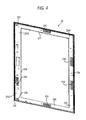
- Fig. 4 is a front view of the front cover 23 of the TV receiver 11 according to the embodiment.
- Fig. 5 is a front view of part of the front cover 23 of the TV receiver 11 according to the embodiment.
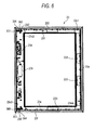
- Fig. 6 is a rear view of the front cover 23 of the TV receiver 11 according to the embodiment.
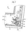
- Fig. 7 is a rear view of part of the front cover 23 of the TV receiver 11 according to the embodiment.
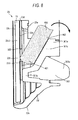
- Fig. 8 shows a process of removing the decorative panel 22 from the front cover 23 according to the embodiment.
- holes 232 through which a jig can be inserted are formed in the respective corner portions 23c2 and 23c3 which are adjacent to the bottom portion 23b.
- the jig means a rod-shaped member such as a screwdriver.
- holes 233 for enabling expansion and contraction of the decorative panel 22 and a hole 234 in which to mount components such as a circuit board (not shown) are formed around the opening 231.
- these holes 232-234 are covered with the decorative panel 22 and hence are not exposed to the outside.
- a projection 300 which projects toward the inside of the cabinet is formed near each hole 232.
- the projection 300 has a cover portion 301 which covers at least part of the hole 232 when viewed from inside the cabinet and a pair of side walls 302 which extend from portions adjacent to the hole 232 and bridge the cover portion 301 and the front cover 23.
- the cover portion 301 has a portion that is opposed to the decorative panel 22 with the hole 232 interposed in between.
- the cover portion 301 has an end portion 301a which is spaced from the front cover 23, a continuous portion 301b which is continuous with the front cover 23, and a slant portion 301c which bridges the end portion 301a and the continuous portion 301b.
- the slant portion 301c extends in a direction that crosses the respective planes in which the front cover 23 and the decorative panel 22 exist. That is, when the TV receiver 11 according to the embodiment is placed on the top plate, for example, of a desk in such a manner that the display screen 16a is approximately perpendicular to the top plate, the slant portion 301c is inclined from the top plate.
- the front cover 23 is provided with bosses 303 each of which is fitted with a fixing member (not shown) for joining the front cover 23 to the back cover 19.
- Each boss 303 is provided with plural boss support portions 303a for supporting the boss 303.
- each projection 300 of the embodiment is provided near the associated boss 303. More specifically, each projection 300 is provided in such a manner that part of the slant portion 301c enters the boss 303.
- the slant portion 301c is integral with some boss support portions 303a.
- One boss support portion 303a extends along a central portion of the slant portion 301c. This structure can increase the rigidity of the projection 300.
- the back surface 23a of the front cover 23 is provided with ribs 304 which extend parallel with the respective side walls 23f.
- Each projection 300 of the embodiment is provided near the associated rib 304. More specifically, part of the slant portion 301c enters the rib 304 and the slant portion 301c is integral with the rib 304.
- the rib 304 extends along the periphery of the end portion 301a. This structure can increase the rigidity of the projection 300.
- each cover portion 301 and the front cover 23 form a hole 302a which is located inside the cabinet and has an open top.
- the hole 302a communicates with the associated hole 232 of the front cover 23. Therefore, in being inserted into the hole 232 from the back side, a jig 400 passes through the hole 302a first and then reaches the hole 232.
- the jig 400 When an end portion (not shown), opposite to a tip portion 401, of the jig 400 is pushed downward in a state that the jig 400 is inserted in the hole 232, that is, the tip portion 401 of the jig 400 is in contact with the decorative panel 22 through the hole 232, the jig 400 is rotated with its portion 402 of contact with the end portion 301a serving as the fulcrum and separates the decorative panel 22 from the portion, around the hole 232, of the front cover 23.
- Indicators 305 indicating that part of the decorative panel 22 can easily be separated from the front cover 23 utilizing the leverage are provided on the back surface 23e of the front cover 23. This allows an operator to recognize that part of the decorative panel 22 can be separated from the front cover 23 utilizing the leverage.
- the indicators 305 are molded together with the front cover 23, the invention is not limited to such a case.
- the indicators 305 may be provided by attaching seals, using paint, or a similar manner.
- part of the decorative panel 22 can easily be separated from the front cover 23 utilizing the leverage.
- the holes 232 of the embodiment are provided in the respective corner portions 23c1 and 23c3 of the front cover 23 which are adjacent to the bottom portion 23b. Therefore, end portions of the decorative panel 22 are peeled off with the jig 400, and hence the decorative panel 22 can easily be separated from the front cover 23 by gripping those end portions.
- each hole 302a has an open top.
- the slant portion 301c exists adjacent to each hole 302a and the associated hole 232 of the front cover 23. Therefore, when inserted into the hole 302a from the side of the top portion 23a of the front cover 23, the jig 400 reaches the hole 232 smoothly being guided by the slant portion 301c.
- each projection 300 is integral with the associated boss 303 and rib 304.
- stress is imposed on the projection 300, in particular, its end portion 301a.
- the projection 300 is integral with the boss 303 and the rib 304, the resistance to the stress occurring in the peeling work can be increased.
- the projections 300 are integral with the front cover 23. This can make the resistance to the stress occurring in the peeling work higher than in a case that the projections 300 are provided separately from the front cover 23.
- Fig. 9 is a rear view of a front cover of a TV receiver according to a modification of the embodiment.
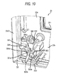
- Fig. 10 shows a process of removing a decorative panel from the front cover according to the modification of the embodiment.
- the TV receiver according to the modification of the embodiment will be described below with reference to Figs. 9 and 10 .
- Members etc. having the same or equivalent (in function) ones in the first embodiment will be given the same reference symbols as the latter and will not be described in detail.
- the members etc. that will not be described below are the same as in the first embodiment.
- a boss 303 and projection 300 that are associated with each other are spaced from each other more than in the embodiment.
- the projection 300 is integral with a rib 304.
- the rib 304 has a reinforcement portion 304a which extends along a central portion of the slant portion 301c.
- the reinforcement portion 304a is thicker than the other portions of the rib 204.
- the reinforcement portion 304a is continuous with one boss support portion 303a. This structure can increase the rigidity of the projection 300 as in the case of the first embodiment.
- the degree of freedom of designing relating to such items as a size change of the TV receiver 11 and a change in the arrangement of mounted components can be increased.
- Electronic apparatus to which the invention is applied are not limited to TV receivers and include displays of personal computers, for example.
- Inventive electronic apparatus can be modified in various manners without departing from the spirit and scope of the invention.
- the present invention may not be limited to the above-mentioned embodiments but can be variously modified.
- Components disclosed in the aforementioned embodiments may be combined suitably to form various modifications.
- some of all components disclosed in the embodiments may be removed or may be appropriately combined.
Landscapes
- Engineering & Computer Science (AREA)
- Microelectronics & Electronic Packaging (AREA)
- Devices For Indicating Variable Information By Combining Individual Elements (AREA)
Abstract
An electronic apparatus includes: a display device comprising a display screen; a cabinet that houses the display device and is provided with a first opening through which the display screen is exposed and a first hole which is located outside the first opening; a first cover member which is attached to the cabinet and covers the first hole; and a cover portion that is provided inside the cabinet at a position spaced from the first cover member, the cover portion covering at least part of the first hole on the side opposite to the first cover member.
Description
- The present application is based upon and claims priority from prior Japanese Patent Application No.
2010-019708, filed on January 29, 2010 - Embodiments described herein generally relate to an electronic apparatus.
- A plasma display apparatus having a configuration suitable for having a large screen size is known. The plasma display apparatus is equipped with a panel having a display screen, a chassis which holds the panel, and a front protective cover which covers the front side of a peripheral portion of the panel. The front protective cover has a front frame having an opening, a protective plate which is made of resin, glass, or the like and attached to the front frame, protective plate pressing metal members for pressing the protective plate from the inside.
- In this type of plasma display apparatus, the protective plate is attached to the front frame in such a manner as to be sandwiched between an opening-side portion of the front frame and the protective plate pressing metal members. An example of such configuration is disclosed in
JP-A-2007-199705 - In large-screen TV monitors, double-sided adhesive tapes may be used for fixing a protective plate or a decorative plate to a front frame. In this case, if trouble occurs such as dust coming into the space between the front frame and the protective plate or decorative plate or a scratch in the front frame, it is necessary to separate the protective plate or decorative plate from the front frame and do reassembling. A structure is desired that allows such work to be conducted efficiently.
- A general configuration that implements the various features of the present invention will be described with reference to the drawings. The drawings and the associated descriptions are provided to illustrate embodiments of the invention and not to limit the scope of the invention.
-
Fig. 1 is a perspective view of a TV receiver according to an embodiment. -
Fig. 2 is a vertical sectional view of the TV receiver according to the embodiment. -
Fig. 3 is an exploded perspective view of a front unit of the TV receiver according to the embodiment. -
Fig. 4 is a front view of a front cover of the TV receiver according to the embodiment. -
Fig. 5 is a front view of part of the front cover of the TV receiver according to the embodiment. -
Fig. 6 is a rear view of the front cover of the TV receiver according to the embodiment. -
Fig. 7 is a rear view of part of the front cover of the TV receiver according to the embodiment. -
Fig. 8 shows a process of removing a decorative panel from the front cover according to the embodiment. -
Fig. 9 is a rear view of a front cover of a TV receiver according to a modification of the embodiment. -
Fig. 10 shows a process of removing a decorative panel from the front cover according to the modification of the embodiment. - According to the embodiments described herein, there is provided an electronic apparatus including: a display device comprising a display screen; a cabinet that houses the display device and is provided with a first opening through which the display screen is exposed and a first hole which is located outside the first opening; a first cover member which is attached to the cabinet and covers the first hole; and a cover portion that is provided inside the cabinet at a position spaced from the first cover member, the cover portion covering at least part of the first hole on the side opposite to the first cover member.
- Embodiments according to the present invention will be described in detail with reference to the accompanying drawings. The scope of the claimed invention should not be limited to the examples illustrated in the drawings and those described in below.
- A TV receiver will be hereinafter described with reference to
Figs. 1-10 as an example of an electronic apparatus according to an embodiment of the present invention. - A configuration of the TV receiver according to the embodiment will be described with reference to
Figs. 1-3 .Fig. 1 is a perspective view of the TV receiver according to the embodiment.Fig. 2 is a vertical sectional view of the TV receiver according to the embodiment.Fig. 3 is an exploded perspective view of a front unit of the TV receiver according to the embodiment. - As shown in
Figs. 1 and2 , theTV receiver 11 is equipped with amain body 12 including aliquid crystal panel 16 and thefront unit 13 which covers the front side of a peripheral portion of theliquid crystal panel 16. Themain body 12 has astand 14 which serves as a support stand of themain body 12, a rectangular-plate-shaped frame 15 which is located over and supported by thestand 14, theliquid crystal panel 16 which is an example display and has adisplay screen 16a, apanel controller 17 for driving theliquid crystal panel 16, apower unit 18 for supplying power to theliquid crystal panel 16 etc., and aback cover 19 which covers themain body 12 from the back side. InFig. 1 , arrows F and R indicate the front side and the back side, respectively, of theTV receiver 11. - The
front unit 13 and theback cover 19 constitute a cabinet which is an outer covering of theTV receiver 11. For example, thepanel controller 17 and thepower unit 18 are fixed to the back surface of theframe 15. Although the embodiment employs theliquid crystal panel 16 as an example display, the invention is not limited to such a case. The display may be any of other display panels such as an organic EL device and a plasma display. - The
front unit 13 is fixed to theframe 13 with such means as screws. As shown inFigs. 3 and4 , thefront unit 13 has adecorative panel 22, afront cover 23 which supports a peripheral portion of thedecorative panel 22, plural through-holes formed through thefront cover 23, andplural bonding members 27 which are sandwiched between thedecorative panel 22 and thefront cover 23. The bondingmembers 27, which are double-sided adhesive tapes, for example, join thedecorative panel 22 and thefront cover 23 to each other. - The
decorative panel 22 of the embodiment has atop portion 22a, abottom portion 22b, corner portions 22c1-22c4, afront surface 22d, and aback surface 22e. For example, thedecorative panel 22 is formed by shaping acrylic resin into a rectangular, frame-shaped plate. Thedecorative panel 22 is provided with anopening 221 for exposing thedisplay screen 16a. Thefront cover 23 has atop portion 23a, abottom portion 23b, corner portions 23c1-23c4, afront surface 23d, aback surface 23e, andside walls 23f. Thefront cover 23 is provided with an opening 231 which corresponds to the opening 221 of thedecorative panel 22 and serves to expose thedisplay screen 16a. - The
decorative panel 22, which is made of an opaque material, a .low-transparency material, or the like, covers at least part of the front surface of thefront cover 23 and can thereby improve the front appearance of theTV receiver 11. - As described above, the
decorative panel 22 of the embodiment is a plate-like member for adding to the beauty of the front surface of thefront cover 23 and is made of such a material as flexible plastics. Thedecorative panel 22 is lower in the probability of damaging thefront cover 23 or thedisplay screen 16a of theliquid crystal panel 16 during work of attaching it than in a case that it is made of a rigid material such as glass or metal. By virtue of its flexibility, thedecorative panel 22 of the embodiment can lower the probability that thedecorative panel 22 itself or thefront cover 23 is damaged in a process of removing it from thefront cover 23. - Since the
decorative panel 22 and thefront cover 23 are prevented from being deformed or damaged when they are separated from each other, they can be reused. Where thedecorative panel 22 and thefront cover 23 are made of different materials, they can easily be discriminated from each other when they are discarded. - Although the embodiment is directed to the example process of separating the
decorative panel 22 from thefront cover 23, the invention is not limited to such a case. For example, the invention can also be applied to a protective panel (not shown) for protecting thedisplay area 16a of theliquid crystal panel 16 and its neighboring region, in which case the invention can increase the efficiency of the work of removing the protective panel from thefront cover 23. - Next, a structure capable of increasing the efficiency of the work of removing the
decorative panel 22 from thefront cover 23 according to the embodiment will be described in detail with reference toFig. 4-8 . -
Fig. 4 is a front view of thefront cover 23 of theTV receiver 11 according to the embodiment.Fig. 5 is a front view of part of thefront cover 23 of theTV receiver 11 according to the embodiment.Fig. 6 is a rear view of thefront cover 23 of theTV receiver 11 according to the embodiment.Fig. 7 is a rear view of part of thefront cover 23 of theTV receiver 11 according to the embodiment.Fig. 8 shows a process of removing thedecorative panel 22 from thefront cover 23 according to the embodiment. - As shown in
Figs. 4 and6 , in thefront cover 23,holes 232 through which a jig can be inserted are formed in the respective corner portions 23c2 and 23c3 which are adjacent to thebottom portion 23b. The jig means a rod-shaped member such as a screwdriver. - In the
front cover 23 of the embodiment, holes 233 for enabling expansion and contraction of thedecorative panel 22 and ahole 234 in which to mount components such as a circuit board (not shown) are formed around theopening 231. In the embodiment, these holes 232-234 are covered with thedecorative panel 22 and hence are not exposed to the outside. - As shown in
Figs. 5 and7 , in thefront cover 23, aprojection 300 which projects toward the inside of the cabinet is formed near eachhole 232. Theprojection 300 has acover portion 301 which covers at least part of thehole 232 when viewed from inside the cabinet and a pair ofside walls 302 which extend from portions adjacent to thehole 232 and bridge thecover portion 301 and thefront cover 23. Thecover portion 301 has a portion that is opposed to thedecorative panel 22 with thehole 232 interposed in between. - As shown in
Figs. 5 ,7 , and8 , thecover portion 301 has anend portion 301a which is spaced from thefront cover 23, acontinuous portion 301b which is continuous with thefront cover 23, and aslant portion 301c which bridges theend portion 301a and thecontinuous portion 301b. Theslant portion 301c extends in a direction that crosses the respective planes in which thefront cover 23 and thedecorative panel 22 exist. That is, when theTV receiver 11 according to the embodiment is placed on the top plate, for example, of a desk in such a manner that thedisplay screen 16a is approximately perpendicular to the top plate, theslant portion 301c is inclined from the top plate. - As shown in
Figs. 7 and8 , thefront cover 23 is provided withbosses 303 each of which is fitted with a fixing member (not shown) for joining thefront cover 23 to theback cover 19. Eachboss 303 is provided with pluralboss support portions 303a for supporting theboss 303. - As shown in
Fig. 7 , eachprojection 300 of the embodiment is provided near the associatedboss 303. More specifically, eachprojection 300 is provided in such a manner that part of theslant portion 301c enters theboss 303. Theslant portion 301c is integral with someboss support portions 303a. Oneboss support portion 303a extends along a central portion of theslant portion 301c. This structure can increase the rigidity of theprojection 300. - As shown in
Fig. 7 , theback surface 23a of thefront cover 23 is provided withribs 304 which extend parallel with therespective side walls 23f. Eachprojection 300 of the embodiment is provided near the associatedrib 304. More specifically, part of theslant portion 301c enters therib 304 and theslant portion 301c is integral with therib 304. Therib 304 extends along the periphery of theend portion 301a. This structure can increase the rigidity of theprojection 300. - As shown in
Figs. 5 ,7 , and8 , eachcover portion 301 and thefront cover 23 form ahole 302a which is located inside the cabinet and has an open top. Thehole 302a communicates with the associatedhole 232 of thefront cover 23. Therefore, in being inserted into thehole 232 from the back side, ajig 400 passes through thehole 302a first and then reaches thehole 232. - When an end portion (not shown), opposite to a
tip portion 401, of thejig 400 is pushed downward in a state that thejig 400 is inserted in thehole 232, that is, thetip portion 401 of thejig 400 is in contact with thedecorative panel 22 through thehole 232, thejig 400 is rotated with itsportion 402 of contact with theend portion 301a serving as the fulcrum and separates thedecorative panel 22 from the portion, around thehole 232, of thefront cover 23. -
Indicators 305 indicating that part of thedecorative panel 22 can easily be separated from thefront cover 23 utilizing the leverage are provided on theback surface 23e of thefront cover 23. This allows an operator to recognize that part of thedecorative panel 22 can be separated from thefront cover 23 utilizing the leverage. Although in the embodiment theindicators 305 are molded together with thefront cover 23, the invention is not limited to such a case. Theindicators 305 may be provided by attaching seals, using paint, or a similar manner. - As described above, according to the embodiment, part of the
decorative panel 22 can easily be separated from thefront cover 23 utilizing the leverage. As described above, theholes 232 of the embodiment are provided in the respective corner portions 23c1 and 23c3 of thefront cover 23 which are adjacent to thebottom portion 23b. Therefore, end portions of thedecorative panel 22 are peeled off with thejig 400, and hence thedecorative panel 22 can easily be separated from thefront cover 23 by gripping those end portions. - In the embodiment, each
hole 302a has an open top. And theslant portion 301c exists adjacent to eachhole 302a and the associatedhole 232 of thefront cover 23. Therefore, when inserted into thehole 302a from the side of thetop portion 23a of thefront cover 23, thejig 400 reaches thehole 232 smoothly being guided by theslant portion 301c. - With the above-described structure, in the embodiment, work of inserting the
jig 400 which is one step of a process of separating thedecorative panel 22 from thefront cover 23 can be conducted easily and its efficiency is increased. - In the embodiment, each
projection 300 is integral with the associatedboss 303 andrib 304. For example, when it is attempted to remove part of thedecorative panel 22 from thefront panel 23 utilizing the leverage by inserting thejig 400 into onehole 302a, stress is imposed on theprojection 300, in particular, itsend portion 301a. However, in the embodiment, since theprojection 300 is integral with theboss 303 and therib 304, the resistance to the stress occurring in the peeling work can be increased. - In the embodiment, the
projections 300 are integral with thefront cover 23. This can make the resistance to the stress occurring in the peeling work higher than in a case that theprojections 300 are provided separately from thefront cover 23. -
Fig. 9 is a rear view of a front cover of a TV receiver according to a modification of the embodiment.Fig. 10 shows a process of removing a decorative panel from the front cover according to the modification of the embodiment. The TV receiver according to the modification of the embodiment will be described below with reference toFigs. 9 and10 . Members etc. having the same or equivalent (in function) ones in the first embodiment will be given the same reference symbols as the latter and will not be described in detail. The members etc. that will not be described below are the same as in the first embodiment. - As shown in
Figs. 9 and10 , in the modification, aboss 303 andprojection 300 that are associated with each other are spaced from each other more than in the embodiment. Theprojection 300 is integral with arib 304. Therib 304 has areinforcement portion 304a which extends along a central portion of theslant portion 301c. Thereinforcement portion 304a is thicker than the other portions of the rib 204. Thereinforcement portion 304a is continuous with oneboss support portion 303a. This structure can increase the rigidity of theprojection 300 as in the case of the first embodiment. - As described above, according to the embodiment and its modification, the degree of freedom of designing relating to such items as a size change of the
TV receiver 11 and a change in the arrangement of mounted components can be increased. - Electronic apparatus to which the invention is applied are not limited to TV receivers and include displays of personal computers, for example. Inventive electronic apparatus can be modified in various manners without departing from the spirit and scope of the invention.
- Although the embodiments according to the present invention have been described above, the present invention may not be limited to the above-mentioned embodiments but can be variously modified. Components disclosed in the aforementioned embodiments may be combined suitably to form various modifications. For example, some of all components disclosed in the embodiments may be removed or may be appropriately combined.
- Additional advantages and modifications will readily occur to those skilled in the art. Therefore, the invention in its broader aspects may not be limited to the specific details and representative embodiments shown and described herein. Accordingly, various modifications may be made without departing from the spirit or scope of the general inventive concept as defined by the appended claims and their equivalents.
Claims (9)
- An electronic apparatus comprising:a display device comprising a display screen;a cabinet that houses the display device and is provided with a first opening through which the display screen is exposed and a first hole which is located outside the first opening;a first cover member which is attached to the cabinet and covers the first hole; anda cover portion that is provided inside the cabinet at a position spaced from the first cover member, the cover portion covering at least part of the first hole on the side opposite to the first cover member.
- The apparatus of Claim 1,
wherein the cover portion is formed to project from a portion near the first hole of the cabinet. - The apparatus of Claim 2,
wherein the first cover member formed in a frame shape and is formed with a second opening through which the display screen is exposed. - The apparatus of Claim 3,
wherein the first hole is located near a corner of the display screen. - The apparatus of Claim 4,
wherein the cabinet comprises a support member,
wherein the first cover member comprises a first end portion and a second end portion which is more distant than the first end portion from the support member, and
wherein the first hole is located at a position that is nearer to the second end portion than to the first end portion. - The apparatus of Claim 5,
wherein the cover portion comprises a second hole which is open on the side opposite to the support member and through which the first hole communicates with the inside of the cabinet. - The apparatus of Claim 6,
wherein at least a part of the cover portion is thicker than a portion that is located in the vicinity of the cover portion. - The apparatus of Claim 7,
wherein the cabinet comprises a first member that is provided with the first opening, the first hole, and the cover portion, a second member, and a boss in which a fixing member for fixing the first member and second member to each other is inserted, and
wherein the cover portion is integral with the boss. - The apparatus of Claim 7,
wherein the cabinet comprises a second cover member which is formed with the first opening and a rib which surrounds the first opening at least partially, and
wherein the cover portion is integral with the rib.
Applications Claiming Priority (1)
| Application Number | Priority Date | Filing Date | Title |
|---|---|---|---|
| JP2010019708A JP5006418B2 (en) | 2010-01-29 | 2010-01-29 | Electronics |
Publications (1)
| Publication Number | Publication Date |
|---|---|
| EP2355123A2 true EP2355123A2 (en) | 2011-08-10 |
Family
ID=44041564
Family Applications (1)
| Application Number | Title | Priority Date | Filing Date |
|---|---|---|---|
| EP10177571A Withdrawn EP2355123A2 (en) | 2010-01-29 | 2010-09-20 | Electronic apparatus |
Country Status (2)
| Country | Link |
|---|---|
| EP (1) | EP2355123A2 (en) |
| JP (1) | JP5006418B2 (en) |
Cited By (1)
| Publication number | Priority date | Publication date | Assignee | Title |
|---|---|---|---|---|
| TWI808389B (en) * | 2021-03-09 | 2023-07-11 | 大陸商東莞市興奇宏電子有限公司 | Display trim jointing structure |
Citations (1)
| Publication number | Priority date | Publication date | Assignee | Title |
|---|---|---|---|---|
| JP2007199705A (en) | 2005-12-27 | 2007-08-09 | Matsushita Electric Ind Co Ltd | Plasma display device |
Family Cites Families (3)
| Publication number | Priority date | Publication date | Assignee | Title |
|---|---|---|---|---|
| JPH1195192A (en) * | 1997-09-19 | 1999-04-09 | Citizen Watch Co Ltd | Liquid crystal display device |
| JP5094331B2 (en) * | 2007-10-22 | 2012-12-12 | 株式会社日立製作所 | Display device |
| JP2009145759A (en) * | 2007-12-17 | 2009-07-02 | Canon Inc | Image display device |
-
2010
- 2010-01-29 JP JP2010019708A patent/JP5006418B2/en not_active Expired - Fee Related
- 2010-09-20 EP EP10177571A patent/EP2355123A2/en not_active Withdrawn
Patent Citations (1)
| Publication number | Priority date | Publication date | Assignee | Title |
|---|---|---|---|---|
| JP2007199705A (en) | 2005-12-27 | 2007-08-09 | Matsushita Electric Ind Co Ltd | Plasma display device |
Cited By (1)
| Publication number | Priority date | Publication date | Assignee | Title |
|---|---|---|---|---|
| TWI808389B (en) * | 2021-03-09 | 2023-07-11 | 大陸商東莞市興奇宏電子有限公司 | Display trim jointing structure |
Also Published As
| Publication number | Publication date |
|---|---|
| JP5006418B2 (en) | 2012-08-22 |
| JP2011158670A (en) | 2011-08-18 |
Similar Documents
| Publication | Publication Date | Title |
|---|---|---|
| JP5504583B2 (en) | Electronic device display device fixing structure and electronic device including the structure | |
| US20180034948A1 (en) | Mobile terminal, shell module, display module, and method of assembling display module | |
| US9341875B2 (en) | Electronic device | |
| KR100617116B1 (en) | Video display device | |
| US20110102343A1 (en) | Holding structure for a touch panel | |
| US8899812B2 (en) | Front bezel assembly with backlight source, non-self-luminous display device with backlight source in front bezel, and method for installing the backlight source thereof | |
| JP4861502B1 (en) | TV, electronics | |
| US7403377B2 (en) | Method of manufacture and an enclosure for a display for an electronic device | |
| JP2002107697A (en) | Display panel | |
| US20070229724A1 (en) | Double-sided display liquid crystal module | |
| US20100053852A1 (en) | Display Device | |
| JP2011249975A (en) | Electronic apparatus | |
| JP2006235425A (en) | Thin display device and method of assembling thin display device | |
| US9182787B2 (en) | Removable cover panel for display housing | |
| US7149079B2 (en) | Electronic apparatus having keyboard | |
| JP2012063473A (en) | Display device | |
| JP5006418B2 (en) | Electronics | |
| EP3582208B1 (en) | Image display apparatus | |
| JP5740994B2 (en) | Electronic equipment mounting jig | |
| JP2013255020A (en) | Portable terminal device and disassembly method of the same | |
| JP2009130538A (en) | Image display device | |
| JP2005352305A (en) | Flat display apparatus and manufacturing method of the same | |
| CN205103515U (en) | display device | |
| JP5771657B2 (en) | Housing and display device | |
| CN211429815U (en) | Circuit board mounting rack convenient to mount and circuit control panel |
Legal Events
| Date | Code | Title | Description |
|---|---|---|---|
| PUAI | Public reference made under article 153(3) epc to a published international application that has entered the european phase |
Free format text: ORIGINAL CODE: 0009012 |
|
| 17P | Request for examination filed |
Effective date: 20100920 |
|
| AK | Designated contracting states |
Kind code of ref document: A2 Designated state(s): AL AT BE BG CH CY CZ DE DK EE ES FI FR GB GR HR HU IE IS IT LI LT LU LV MC MK MT NL NO PL PT RO SE SI SK SM TR |
|
| AX | Request for extension of the european patent |
Extension state: BA ME RS |
|
| STAA | Information on the status of an ep patent application or granted ep patent |
Free format text: STATUS: THE APPLICATION HAS BEEN WITHDRAWN |
|
| 18W | Application withdrawn |
Effective date: 20150603 |