EP2354496A2 - Brake mechanism for air turbine starter - Google Patents
Brake mechanism for air turbine starter Download PDFInfo
- Publication number
- EP2354496A2 EP2354496A2 EP11250131A EP11250131A EP2354496A2 EP 2354496 A2 EP2354496 A2 EP 2354496A2 EP 11250131 A EP11250131 A EP 11250131A EP 11250131 A EP11250131 A EP 11250131A EP 2354496 A2 EP2354496 A2 EP 2354496A2
- Authority
- EP
- European Patent Office
- Prior art keywords
- brake
- starter
- turbine wheel
- turbine
- piston
- Prior art date
- Legal status (The legal status is an assumption and is not a legal conclusion. Google has not performed a legal analysis and makes no representation as to the accuracy of the status listed.)
- Withdrawn
Links
Images


Classifications
-
- F—MECHANICAL ENGINEERING; LIGHTING; HEATING; WEAPONS; BLASTING
- F02—COMBUSTION ENGINES; HOT-GAS OR COMBUSTION-PRODUCT ENGINE PLANTS
- F02C—GAS-TURBINE PLANTS; AIR INTAKES FOR JET-PROPULSION PLANTS; CONTROLLING FUEL SUPPLY IN AIR-BREATHING JET-PROPULSION PLANTS
- F02C7/00—Features, components parts, details or accessories, not provided for in, or of interest apart form groups F02C1/00 - F02C6/00; Air intakes for jet-propulsion plants
- F02C7/26—Starting; Ignition
- F02C7/268—Starting drives for the rotor, acting directly on the rotor of the gas turbine to be started
- F02C7/275—Mechanical drives
- F02C7/277—Mechanical drives the starter being a separate turbine
-
- F—MECHANICAL ENGINEERING; LIGHTING; HEATING; WEAPONS; BLASTING
- F05—INDEXING SCHEMES RELATING TO ENGINES OR PUMPS IN VARIOUS SUBCLASSES OF CLASSES F01-F04
- F05D—INDEXING SCHEME FOR ASPECTS RELATING TO NON-POSITIVE-DISPLACEMENT MACHINES OR ENGINES, GAS-TURBINES OR JET-PROPULSION PLANTS
- F05D2260/00—Function
- F05D2260/90—Braking
- F05D2260/902—Braking using frictional mechanical forces
-
- F—MECHANICAL ENGINEERING; LIGHTING; HEATING; WEAPONS; BLASTING
- F16—ENGINEERING ELEMENTS AND UNITS; GENERAL MEASURES FOR PRODUCING AND MAINTAINING EFFECTIVE FUNCTIONING OF MACHINES OR INSTALLATIONS; THERMAL INSULATION IN GENERAL
- F16D—COUPLINGS FOR TRANSMITTING ROTATION; CLUTCHES; BRAKES
- F16D2121/00—Type of actuator operation force
- F16D2121/02—Fluid pressure
- F16D2121/12—Fluid pressure for releasing a normally applied brake, the type of actuator being irrelevant or not provided for in groups F16D2121/04 - F16D2121/10
Definitions
- the subject matter disclosed herein generally relates to air-driven turbine starters. More specifically, the subject disclosure relates to braking mechanisms for air-driven turbine starters.
- Aircraft engines for example, gas turbines, are typically equipped with an air-driven turbine starter mounted on the accessory gearbox, whose purpose is to bring the turbine up to a light-off speed prior to ignition of the engine combustor.
- the turbine starter is driven by pressurized air provided by an air source such as an auxiliary power unit, another operating engine, or an external air cart connected to the turbine starter. Pressurized air fed into the turbine starter drives is converted to mechanical power causing rotation of a starter output shaft.
- the starter output shaft transmits this rotation to the drive shaft of the accessory gearbox. Rotation of the gearbox shaft drives the engine which induces airflow into the engine. When the engine rotation reaches a desired speed, combustion is initiated and assists the starter in engine acceleration until the turbine starter is no longer necessary.
- the flow of pressurized air into the air turbine starter is thus cut off, causing rotation of the starter shaft to slow.
- the starter is disengaged via the action of a clutch internal to the turbine starter, for example, a synchronous engagement clutch (SEC) as described in U.S. Patent 5,419,420 .
- SEC synchronous engagement clutch
- the SEC operates by moving clutch elements associated with the starter shaft away from clutch elements associated with the gearbox shaft as the rotation of the starter shaft slows.
- the clutch elements associated with the starter shaft ratchet along the clutch elements associated with the gearbox shaft until the starter shaft slows sufficiently to move the clutch elements associated with the starter shaft a necessary distance to achieve full disengagement.
- the ratcheting during clutch disengagement contributes to wear of said clutch elements. As such, to reduce wear on the clutch elements and extend their service lives, it is desirable to reduce turbine starter speed quickly so that clutch engagement/disengagement and thus ratcheting time is reduced.
- a brake assembly for an air turbine starter includes a brake cylinder located in the air turbine starter.
- a brake piston is located at least partially within the brake cylinder and slidable therein.
- a biasing member biases the brake piston toward a turbine wheel of the air turbine starter applying a braking force to the turbine wheel and defining a piston chamber between the turbine wheel and the brake piston.
- a through opening in the brake piston into the piston chamber is configured such that a flow of fluid through the opening into the piston chamber applies a force to the brake piston sufficient to overcome the bias thereby allowing rotation of the turbine wheel.
- an air turbine starter includes a housing having an inlet receivable of a flow of fluid and a turbine wheel disposed therein including a plurality of turbine blades.
- a starter shaft is operably connected to the turbine wheel such that rotation of the turbine wheel drives rotation of the starter shaft.
- a brake assembly disposed in the housing includes a brake cylinder and a brake piston disposed at least partially within the brake cylinder and slidable therein.
- a biasing member biases the brake piston toward the turbine wheel applying a braking force to the turbine wheel and defining a piston chamber between the turbine wheel and the brake piston.
- a through opening in the brake piston into the piston chamber is configured such that a flow of fluid through the through opening into the piston chamber applies a force to the brake piston sufficient to overcome the bias thereby allowing rotation of the turbine wheel.
- a method of controlling rotation of a turbine wheel of an air turbine starter includes locating a brake assembly at a housing of the air turbine starter.
- the brake assembly includes a brake cylinder, a brake piston located at least partially within the brake cylinder and slidable therein, and a biasing member configured to bias the brake piston toward the turbine wheel.
- a braking force is applied to the turbine wheel sufficient to resist rotation of the turbine wheel due to the action of a biasing member on the brake piston.
- FIG. 1 is a cross-sectional view of an embodiment of an air turbine starter
- FIG. 2 is a partial cross-sectional view of an embodiment of an air turbine starter
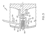
- FIG. 3 is an enlarged view of a portion of the air turbine starter of FIG. 2 .
- the air turbine starter 10 includes a turbine wheel 12 that is driven by a compressed gas, from a source such as an auxiliary power unit (APU), another operating engine, or an external air cart.
- the air turbine starter 10 has a gear housing 14 disposed between and mounted to an inlet housing 16 and a transmission housing 18.
- the inlet housing 16 defines a flow chamber 20 having a flow inlet 22, through which the compressed gas enters the air turbine starter 10, and a flow outlet 24.
- the turbine wheel 12 is disposed in the flow chamber 20 between the flow inlet 22 and the flow outlet 24 and includes a plurality of blades 26 disposed circumferentially around the turbine wheel 12.
- the turbine wheel 12 further includes a central axially-extending starter shaft 28.
- the turbine wheel 12 is mounted to the starter shaft 28 such that the starter shaft 28 is driven in rotation about its axis as the turbine wheel 12 is driven to rotate about its axis by the compressed gas passing through the plurality of blades 26 to the flow outlet 24.
- a flow deflector 34 may be disposed in the flow chamber 20 downstream of the turbine wheel 12 to direct the compressed gas toward the flow outlet 24.
- the energy extracted from the compressed gas via the turbine wheel 12 is transmitted via the starter shaft 28 into an output shaft 36 via a clutch assembly 38.
- the clutch assembly 38 is a synchronous engagement clutch, but other types of clutches are contemplated within the scope of the present disclosure.
- the clutch assembly 38 includes a starter spline 40 associated with and connected to the starter shaft 28 and an input spline 42 associated with and connected to the output shaft 36.
- the starter spline 40 is biased toward engagement with the input spline 42 when the air turbine starter 10 is operating until a cut-off speed of the starter shaft 28 is reached. At that speed, the supply of compressed gas to the air turbine starter 10 is stopped and the clutch assembly 38 begins to disengage. Complete disengagement of the clutch assembly 38 occurs when the turbine shaft 28 stops rotating.
- the air turbine starter 10 includes a turbine brake 44.
- the turbine brake 44 is disposed between the turbine shield 30 and the turbine wheel 12.
- FIG. 3 the turbine brake 44 is shown in more detail.
- the turbine brake 44 includes a brake cylinder 46 affixed to the turbine shield 30.
- a brake piston 48 is disposed in the brake cylinder 46 and biased toward the turbine wheel 12 by, for example, a coil spring 50 or other means located in a spring cavity 62.
- the coil spring 50 is also generally referred to as biasing member 50, and the spring cavity 62 is also referred to as bias cavity 62.
- a piston arm 52 is attached to the brake piston 48.
- the piston arm 52 is configured such that the piston arm 52 contacts the turbine wheel 12 and applies a braking force thereto when there is no flow of compressed gas into the air turbine starter 10, thus preventing rotation of the turbine wheel 12.
- the brake piston 48 includes a pipe hole 56 which, in some embodiments, extends along a length of the brake piston 48.
- the pipe hole 56 also referred to as through opening 56, allows the compressed gas to enter a piston chamber 58 between the piston arm 52 and the turbine wheel 12.
- the compressed gas entering the piston chamber 58 sufficiently pressurizes the piston chamber 58 to, for example, about 30 pounds per square inch, to overcome the bias force of the coil spring 50 and forces the brake piston 48 and piston arm 52 away from the turbine wheel 12 thus allowing the turbine wheel 12 to rotate.
- the turbine brake 44 includes at least one air release 60 which extends from the brake cylinder 46 through the stator vanes 32 and out of the inlet housing 16 as depicted in FIG. 2 .
- the air release 60 vents the spring cavity 62 if necessary to ensure sufficient force is exerted on the brake piston 48 to ensure translation away from the turbine wheel 12.
Landscapes
- Engineering & Computer Science (AREA)
- Chemical & Material Sciences (AREA)
- Combustion & Propulsion (AREA)
- Mechanical Engineering (AREA)
- General Engineering & Computer Science (AREA)
- Control Of Turbines (AREA)
- Braking Arrangements (AREA)
Abstract
A brake assembly (44) for an air turbine starter (10) includes a brake cylinder (46). A brake piston (48) is located at least partially within the brake cylinder (46) and slidable therein. A biasing member (50) biases the brake piston (48) toward a turbine wheel (12) of the air turbine starter (10) applying a braking force to the turbine wheel (12) and defining a piston chamber (58) between the turbine wheel (12) and the brake piston (48). A through opening (56) in the brake piston (48) into the piston chamber (58) is configured such that a flow of fluid through the through opening (56) into the piston chamber (58) applies a force to the brake piston (48) sufficient to overcome the bias thereby allowing rotation of the turbine wheel (12).
Description
- The subject matter disclosed herein generally relates to air-driven turbine starters. More specifically, the subject disclosure relates to braking mechanisms for air-driven turbine starters.
- Aircraft engines, for example, gas turbines, are typically equipped with an air-driven turbine starter mounted on the accessory gearbox, whose purpose is to bring the turbine up to a light-off speed prior to ignition of the engine combustor. The turbine starter is driven by pressurized air provided by an air source such as an auxiliary power unit, another operating engine, or an external air cart connected to the turbine starter. Pressurized air fed into the turbine starter drives is converted to mechanical power causing rotation of a starter output shaft. The starter output shaft transmits this rotation to the drive shaft of the accessory gearbox. Rotation of the gearbox shaft drives the engine which induces airflow into the engine. When the engine rotation reaches a desired speed, combustion is initiated and assists the starter in engine acceleration until the turbine starter is no longer necessary. The flow of pressurized air into the air turbine starter is thus cut off, causing rotation of the starter shaft to slow. As the starter shaft slows, the starter is disengaged via the action of a clutch internal to the turbine starter, for example, a synchronous engagement clutch (SEC) as described in
U.S. Patent 5,419,420 . The SEC operates by moving clutch elements associated with the starter shaft away from clutch elements associated with the gearbox shaft as the rotation of the starter shaft slows. During the disengagement process, the clutch elements associated with the starter shaft ratchet along the clutch elements associated with the gearbox shaft until the starter shaft slows sufficiently to move the clutch elements associated with the starter shaft a necessary distance to achieve full disengagement. The ratcheting during clutch disengagement contributes to wear of said clutch elements. As such, to reduce wear on the clutch elements and extend their service lives, it is desirable to reduce turbine starter speed quickly so that clutch engagement/disengagement and thus ratcheting time is reduced. - According to one aspect of the invention, a brake assembly for an air turbine starter includes a brake cylinder located in the air turbine starter. A brake piston is located at least partially within the brake cylinder and slidable therein. A biasing member biases the brake piston toward a turbine wheel of the air turbine starter applying a braking force to the turbine wheel and defining a piston chamber between the turbine wheel and the brake piston. A through opening in the brake piston into the piston chamber is configured such that a flow of fluid through the opening into the piston chamber applies a force to the brake piston sufficient to overcome the bias thereby allowing rotation of the turbine wheel.
- According to another aspect of the invention, an air turbine starter includes a housing having an inlet receivable of a flow of fluid and a turbine wheel disposed therein including a plurality of turbine blades. A starter shaft is operably connected to the turbine wheel such that rotation of the turbine wheel drives rotation of the starter shaft. A brake assembly disposed in the housing includes a brake cylinder and a brake piston disposed at least partially within the brake cylinder and slidable therein. A biasing member biases the brake piston toward the turbine wheel applying a braking force to the turbine wheel and defining a piston chamber between the turbine wheel and the brake piston. A through opening in the brake piston into the piston chamber is configured such that a flow of fluid through the through opening into the piston chamber applies a force to the brake piston sufficient to overcome the bias thereby allowing rotation of the turbine wheel.
- According to yet another aspect of the invention, a method of controlling rotation of a turbine wheel of an air turbine starter includes locating a brake assembly at a housing of the air turbine starter. The brake assembly includes a brake cylinder, a brake piston located at least partially within the brake cylinder and slidable therein, and a biasing member configured to bias the brake piston toward the turbine wheel. A braking force is applied to the turbine wheel sufficient to resist rotation of the turbine wheel due to the action of a biasing member on the brake piston.
- These and other advantages and features will become more apparent from the following description taken in conjunction with the drawings.
- The subject matter, which is regarded as the invention, is particularly pointed out and distinctly claimed in the claims at the conclusion of the specification. The foregoing and other features, and advantages of the invention are apparent from the following detailed description taken in conjunction with the accompanying drawings in which:
-
FIG. 1 is a cross-sectional view of an embodiment of an air turbine starter; -
FIG. 2 is a partial cross-sectional view of an embodiment of an air turbine starter; and -
FIG. 3 is an enlarged view of a portion of the air turbine starter ofFIG. 2 . - The detailed description explains embodiments of the invention, together with advantages and features, by way of example with reference to the drawings.
- Shown in
FIG. 1 is an embodiment of anair turbine starter 10. Theair turbine starter 10 includes aturbine wheel 12 that is driven by a compressed gas, from a source such as an auxiliary power unit (APU), another operating engine, or an external air cart. Theair turbine starter 10 has agear housing 14 disposed between and mounted to aninlet housing 16 and atransmission housing 18. Theinlet housing 16 defines aflow chamber 20 having aflow inlet 22, through which the compressed gas enters theair turbine starter 10, and aflow outlet 24. Theturbine wheel 12 is disposed in theflow chamber 20 between theflow inlet 22 and theflow outlet 24 and includes a plurality ofblades 26 disposed circumferentially around theturbine wheel 12. Theturbine wheel 12 further includes a central axially-extendingstarter shaft 28. Theturbine wheel 12 is mounted to thestarter shaft 28 such that thestarter shaft 28 is driven in rotation about its axis as theturbine wheel 12 is driven to rotate about its axis by the compressed gas passing through the plurality ofblades 26 to theflow outlet 24. Aturbine shield 30, having a plurality ofstator vanes 32 disposed circumferentially thereabout, is disposed in theflow chamber 20 upstream of thestator wheel 12 to direct the compressed gas from theflow inlet 22 toward the plurality ofblades 26 in a desired manner. In some embodiments, aflow deflector 34 may be disposed in theflow chamber 20 downstream of theturbine wheel 12 to direct the compressed gas toward theflow outlet 24. - The energy extracted from the compressed gas via the
turbine wheel 12 is transmitted via thestarter shaft 28 into anoutput shaft 36 via aclutch assembly 38. In the embodiment shown inFIG.1 , theclutch assembly 38 is a synchronous engagement clutch, but other types of clutches are contemplated within the scope of the present disclosure. Theclutch assembly 38 includes astarter spline 40 associated with and connected to thestarter shaft 28 and aninput spline 42 associated with and connected to theoutput shaft 36. Thestarter spline 40 is biased toward engagement with theinput spline 42 when theair turbine starter 10 is operating until a cut-off speed of thestarter shaft 28 is reached. At that speed, the supply of compressed gas to theair turbine starter 10 is stopped and theclutch assembly 38 begins to disengage. Complete disengagement of theclutch assembly 38 occurs when theturbine shaft 28 stops rotating. - Referring to
FIG. 2 , to speed complete disengagement of theclutch assembly 38 ofFIG. 1 , theair turbine starter 10 includes aturbine brake 44. Theturbine brake 44 is disposed between theturbine shield 30 and theturbine wheel 12. Referring now toFIG. 3 , theturbine brake 44 is shown in more detail. Theturbine brake 44 includes abrake cylinder 46 affixed to theturbine shield 30. Abrake piston 48 is disposed in thebrake cylinder 46 and biased toward theturbine wheel 12 by, for example, acoil spring 50 or other means located in aspring cavity 62. Thecoil spring 50 is also generally referred to as biasingmember 50, and thespring cavity 62 is also referred to asbias cavity 62. Apiston arm 52 is attached to thebrake piston 48. Thepiston arm 52 is configured such that thepiston arm 52 contacts theturbine wheel 12 and applies a braking force thereto when there is no flow of compressed gas into theair turbine starter 10, thus preventing rotation of theturbine wheel 12. - When operation of the
air turbine starter 10 is begun and compressed gas is flowed through theflow inlet 22, a portion of the compressed gas flows through a plurality ofshield holes 54 in theturbine shield 30. Thebrake piston 48 includes apipe hole 56 which, in some embodiments, extends along a length of thebrake piston 48. Thepipe hole 56, also referred to as throughopening 56, allows the compressed gas to enter apiston chamber 58 between thepiston arm 52 and theturbine wheel 12. The compressed gas entering thepiston chamber 58 sufficiently pressurizes thepiston chamber 58 to, for example, about 30 pounds per square inch, to overcome the bias force of thecoil spring 50 and forces thebrake piston 48 andpiston arm 52 away from theturbine wheel 12 thus allowing theturbine wheel 12 to rotate. In some embodiments, theturbine brake 44 includes at least oneair release 60 which extends from thebrake cylinder 46 through thestator vanes 32 and out of theinlet housing 16 as depicted inFIG. 2 . Theair release 60 vents thespring cavity 62 if necessary to ensure sufficient force is exerted on thebrake piston 48 to ensure translation away from theturbine wheel 12. - When the
air turbine starter 10 is turned off, for example, when the engine is successfully started, the flow of compressed gas through theflow inlet 22 is stopped. Consequently, flow of compressed air through thepipe hole 56 into thepiston chamber 58 ceases, thus allowing thecoil spring 50 to force thepiston arm 52 into contact with theturbine wheel 12. Thepiston arm 52 applies a braking force to theturbine wheel 12 to quickly bring theturbine wheel 12 to a stop, thus reducing the disengagement time of theclutch assembly 38 to reduce wear of theclutch assembly 38. The reduction of engagement time reduces ratcheting of the teeth of thestarter spline 40 and theinput spline 42 ofFIG. 1 , thereby reducing wear. - While the invention has been described in detail in connection with only a limited number of embodiments, it should be readily understood that the invention is not limited to such disclosed embodiments. Rather, the invention can be modified to incorporate any number of variations, alterations, substitutions or equivalent arrangements not heretofore described. Additionally, while various embodiments of the invention have been described, it is to be understood that aspects of the invention may include only some of the described embodiments. Accordingly, the invention is not to be seen as limited by the foregoing description, but is only limited by the scope of the appended claims.
Claims (15)
- A brake assembly (44) for an air turbine starter (10) comprising:a brake cylinder (46);a brake piston (48) disposed at least partially within the brake cylinder (46) and slidable therein;a biasing member (50) to bias the brake piston (48) toward a turbine wheel (12) of the air turbine starter (10) applying a braking force to the turbine wheel (12) and defining a piston chamber (58) between the turbine wheel (12) and the brake piston (48); anda through opening (56) in the brake piston (48) into the piston chamber (58) configured such that a flow of fluid through the through opening (56) into the piston chamber (58) applies a force to the brake piston (48) sufficient to overcome the bias thereby allowing rotation of the turbine wheel (12).
- The brake assembly (44) of Claim 1 wherein the brake piston (48) is configured to travel axially away from the turbine wheel (12) when the bias is overcome.
- The brake assembly (44) of Claim 1 or 2 wherein the biasing member (50) is a coil spring (50).
- The brake assembly (44) of Claim 1, 2 or 3 wherein the biasing member (50) is disposed at a bias cavity (62) in the brake cylinder (46).
- The brake assembly (44) of Claim 4 including at least one release opening (60) disposed at the brake cylinder (46) to prevent pressurization of bias cavity (62).
- The brake assembly (44) of any preceding Claim wherein the flow of fluid is compressed gas.
- An air turbine starter (10) comprising:a housing (16) having an inlet (22) receivable of a flow of fluid;a turbine wheel (12) disposed in the housing (16), the turbine wheel (12) including a plurality of turbine blades (26) disposed thereat;a starter shaft (28) operably connected to the turbine wheel (12) such that rotation of the turbine wheel (12) drives rotation of the starter shaft (28); andthe brake assembly of any of claims 1 to 5.
- The air turbine starter (10) of Claim 7 further comprising an output shaft (36) in operable communication with the starter shaft (28) via a clutch assembly (38).
- The air turbine starter (10) of Claim 8 wherein the clutch assembly (38) is a synchronous engagement clutch.
- The air turbine starter (10) of Claim 8 or 9 where engagement of the brake assembly (44) to stop rotation of the turbine wheel (12) disengages the clutch assembly (38) between the starter shaft (28) and the output shaft (36).
- The air turbine starter (10) of any of Claims 7 to 10 including at least one release (60) disposed at the brake cylinder (46) to prevent over pressurization of the brake cylinder (46).
- The air turbine starter (10) of Claim 11 wherein the at least one release (60) extends through at least one stator member (32) disposed between the inlet (22) and the turbine wheel (12).
- The air turbine starter (10) of any of Claims 7 to 12 wherein the flow of fluid is compressed gas.
- A method of controlling rotation of a turbine wheel (12) of an air turbine starter (10) comprising:disposing a brake assembly (44) at a housing (16) of the air turbine starter (10), the brake assembly (44) including:a brake cylinder (46);a brake piston (48) disposed at least partially within the brake cylinder (46) and slidable therein; anda biasing member (50) configured to bias the brake piston (48) toward the turbine wheel (12); andapplying a braking force on the turbine wheel (12) sufficient to resist rotation of the turbine wheel (12) due to the action of a biasing member on the brake piston (48).
- The method of Claim 14 comprising:injecting a flow of fluid into a piston chamber (58) defined between the turbine wheel (12) and the brake piston (48); andovercoming the braking force via pressurization of the piston chamber (58) by urging the brake piston (48) away from the turbine wheel (12) to allow rotation of the turbine wheel (12); preferably wherein the flow of fluid is injected into the piston chamber (58) via one or more through openings (56) in the brake piston (48).
Applications Claiming Priority (1)
| Application Number | Priority Date | Filing Date | Title |
|---|---|---|---|
| US12/700,337 US8678747B2 (en) | 2010-02-04 | 2010-02-04 | Brake mechanism for air turbine starter |
Publications (1)
| Publication Number | Publication Date |
|---|---|
| EP2354496A2 true EP2354496A2 (en) | 2011-08-10 |
Family
ID=43927981
Family Applications (1)
| Application Number | Title | Priority Date | Filing Date |
|---|---|---|---|
| EP11250131A Withdrawn EP2354496A2 (en) | 2010-02-04 | 2011-02-04 | Brake mechanism for air turbine starter |
Country Status (3)
| Country | Link |
|---|---|
| US (1) | US8678747B2 (en) |
| EP (1) | EP2354496A2 (en) |
| CA (1) | CA2730852A1 (en) |
Cited By (1)
| Publication number | Priority date | Publication date | Assignee | Title |
|---|---|---|---|---|
| EP3954884A1 (en) * | 2020-08-13 | 2022-02-16 | Unison Industries LLC | Air turbine starter with primary and secondary air flow paths |
Families Citing this family (4)
| Publication number | Priority date | Publication date | Assignee | Title |
|---|---|---|---|---|
| EP2570621A1 (en) | 2011-09-15 | 2013-03-20 | Siemens Aktiengesellschaft | Device for pivoting a rotor of a fluid flow engine from a first position to a second position |
| CN104533631A (en) * | 2014-12-03 | 2015-04-22 | 中国航空工业集团公司金城南京机电液压工程研究中心 | Air turbine starter turbine class-front pressure restriction apparatus |
| CN110332260B (en) * | 2019-08-12 | 2021-09-24 | 湖北康晨安宝矿业设备有限责任公司 | Front axle traveling and parking integrated brake |
| CN119878418B (en) * | 2024-12-31 | 2025-10-21 | 中国船舶集团有限公司第七一一研究所 | Starter motor turbine and engine |
Citations (1)
| Publication number | Priority date | Publication date | Assignee | Title |
|---|---|---|---|---|
| US5419420A (en) | 1992-10-05 | 1995-05-30 | United Technologies, Corp. | Flyweight actuated clutch |
Family Cites Families (3)
| Publication number | Priority date | Publication date | Assignee | Title |
|---|---|---|---|---|
| US2987296A (en) * | 1957-12-02 | 1961-06-06 | Bendix Corp | Safety device for starter turbine |
| US3203514A (en) * | 1963-04-10 | 1965-08-31 | Caterpillar Tractor Co | Turbocharger brake |
| US5042963A (en) * | 1989-03-31 | 1991-08-27 | Allied-Signal Inc. | Dual range air turbine starter |
-
2010
- 2010-02-04 US US12/700,337 patent/US8678747B2/en not_active Expired - Fee Related
-
2011
- 2011-02-02 CA CA2730852A patent/CA2730852A1/en not_active Abandoned
- 2011-02-04 EP EP11250131A patent/EP2354496A2/en not_active Withdrawn
Patent Citations (1)
| Publication number | Priority date | Publication date | Assignee | Title |
|---|---|---|---|---|
| US5419420A (en) | 1992-10-05 | 1995-05-30 | United Technologies, Corp. | Flyweight actuated clutch |
Cited By (2)
| Publication number | Priority date | Publication date | Assignee | Title |
|---|---|---|---|---|
| EP3954884A1 (en) * | 2020-08-13 | 2022-02-16 | Unison Industries LLC | Air turbine starter with primary and secondary air flow paths |
| US11624323B2 (en) | 2020-08-13 | 2023-04-11 | Unison Industries, Llc | Air turbine starter with primary and secondary air flow paths |
Also Published As
| Publication number | Publication date |
|---|---|
| CA2730852A1 (en) | 2011-08-04 |
| US20110188997A1 (en) | 2011-08-04 |
| US8678747B2 (en) | 2014-03-25 |
Similar Documents
| Publication | Publication Date | Title |
|---|---|---|
| JP5442707B2 (en) | Turbine engine including reversible electric machine | |
| US4799354A (en) | Turbopropeller or turbofan gas turbine engine | |
| EP2407644B1 (en) | Geared turbofan | |
| EP2133537B1 (en) | Bi-modal air turbine starter assembly | |
| EP2772438B1 (en) | Auxiliary power units (APUs) and methods and systems for activation and deactivation of a load compressor therein | |
| US8678747B2 (en) | Brake mechanism for air turbine starter | |
| EP2415991B1 (en) | Clutch between auxiliary gear box and starter-generator of a turbofan engine | |
| CA2920610C (en) | System for braking a low pressure spool in a gas turbine engine | |
| JP2008510916A (en) | Gas turbine braking apparatus and method | |
| CN109306901B (en) | Air turbine starter | |
| GB2566795A (en) | Air turbine starter | |
| CN102383943A (en) | Auxiliary hydraulic power generation system | |
| EP3434880B1 (en) | Air turbine starter | |
| GB2566796A (en) | Air turbine starter | |
| EP3434882B1 (en) | Air turbine starter | |
| CN109306900B (en) | Air turbine starter | |
| CN111188850B (en) | Actuator Failure Fixing System | |
| US20120006035A1 (en) | Turbine rim cutter for air turbine starter | |
| CN109306905B (en) | Air turbine starter | |
| US20100077769A1 (en) | Starter drive assembly and method of starting a gas turbine engine |
Legal Events
| Date | Code | Title | Description |
|---|---|---|---|
| PUAI | Public reference made under article 153(3) epc to a published international application that has entered the european phase |
Free format text: ORIGINAL CODE: 0009012 |
|
| AK | Designated contracting states |
Kind code of ref document: A2 Designated state(s): AL AT BE BG CH CY CZ DE DK EE ES FI FR GB GR HR HU IE IS IT LI LT LU LV MC MK MT NL NO PL PT RO RS SE SI SK SM TR |
|
| AX | Request for extension of the european patent |
Extension state: BA ME |
|
| STAA | Information on the status of an ep patent application or granted ep patent |
Free format text: STATUS: THE APPLICATION HAS BEEN WITHDRAWN |
|
| 18W | Application withdrawn |
Effective date: 20131219 |