EP2354471A2 - Sealing and purging arrangement for a main bearing region - Google Patents
Sealing and purging arrangement for a main bearing region Download PDFInfo
- Publication number
- EP2354471A2 EP2354471A2 EP10196266A EP10196266A EP2354471A2 EP 2354471 A2 EP2354471 A2 EP 2354471A2 EP 10196266 A EP10196266 A EP 10196266A EP 10196266 A EP10196266 A EP 10196266A EP 2354471 A2 EP2354471 A2 EP 2354471A2
- Authority
- EP
- European Patent Office
- Prior art keywords
- flow
- air
- bearing
- gap
- allows
- Prior art date
- Legal status (The legal status is an assumption and is not a legal conclusion. Google has not performed a legal analysis and makes no representation as to the accuracy of the status listed.)
- Withdrawn
Links
- 238000010926 purge Methods 0.000 title claims abstract description 18
- 238000007789 sealing Methods 0.000 title claims abstract description 15
- 239000003570 air Substances 0.000 claims description 84
- 239000012080 ambient air Substances 0.000 claims description 12
- 238000000034 method Methods 0.000 description 10
- 229910001141 Ductile iron Inorganic materials 0.000 description 1
- 230000004075 alteration Effects 0.000 description 1
- 230000000903 blocking effect Effects 0.000 description 1
- 230000000694 effects Effects 0.000 description 1
- 239000000463 material Substances 0.000 description 1
- 239000002184 metal Substances 0.000 description 1
- 229910052751 metal Inorganic materials 0.000 description 1
- 238000006467 substitution reaction Methods 0.000 description 1
Images

Classifications
-
- F—MECHANICAL ENGINEERING; LIGHTING; HEATING; WEAPONS; BLASTING
- F01—MACHINES OR ENGINES IN GENERAL; ENGINE PLANTS IN GENERAL; STEAM ENGINES
- F01D—NON-POSITIVE DISPLACEMENT MACHINES OR ENGINES, e.g. STEAM TURBINES
- F01D25/00—Component parts, details, or accessories, not provided for in, or of interest apart from, other groups
- F01D25/16—Arrangement of bearings; Supporting or mounting bearings in casings
-
- F—MECHANICAL ENGINEERING; LIGHTING; HEATING; WEAPONS; BLASTING
- F01—MACHINES OR ENGINES IN GENERAL; ENGINE PLANTS IN GENERAL; STEAM ENGINES
- F01D—NON-POSITIVE DISPLACEMENT MACHINES OR ENGINES, e.g. STEAM TURBINES
- F01D25/00—Component parts, details, or accessories, not provided for in, or of interest apart from, other groups
- F01D25/18—Lubricating arrangements
- F01D25/183—Sealing means
-
- F—MECHANICAL ENGINEERING; LIGHTING; HEATING; WEAPONS; BLASTING
- F02—COMBUSTION ENGINES; HOT-GAS OR COMBUSTION-PRODUCT ENGINE PLANTS
- F02C—GAS-TURBINE PLANTS; AIR INTAKES FOR JET-PROPULSION PLANTS; CONTROLLING FUEL SUPPLY IN AIR-BREATHING JET-PROPULSION PLANTS
- F02C7/00—Features, components parts, details or accessories, not provided for in, or of interest apart form groups F02C1/00 - F02C6/00; Air intakes for jet-propulsion plants
- F02C7/06—Arrangements of bearings; Lubricating
Definitions
- the subject matter disclosed herein relates to main bearings and, more particularly, to a sealing and purging arrangement at a main bearing region.
- a gas turbine includes a main rotor that requires sealing of the main bearing to prevent leakage of the bearing oil in the bearing housing or compartment. Such leakage may cause operational issues for the gas turbine. It is known to use labyrinth seals in the sealing of the bearing housing. However, these labyrinth seals oftentimes pose added cost and reliability issues.
- apparatus for sealing and purging a bearing region includes a bearing housing having at least one hole that allows a flow of air to flow through the at least one hole, and at least one bearing seal that allows the flow of air to flow through the at least one bearing seal, thereby creating a pressure difference across the bearing seal.
- the apparatus also includes an air directional device having at least a portion of the flow of air to flow adjacent to the air directional device, and a pair of components having a gap between the pair of components that allows the at least a portion of the flow of air to flow through the gap, thereby purging the gap.
- apparatus for sealing and purging a bearing region includes a bearing housing having at least one hole that allows a flow of air to flow through the at least one hole, and at least one bearing seal that allows the flow of air to flow through the at least one bearing seal, thereby creating a pressure difference across the bearing seal.
- the apparatus also includes an air directional device having at least a portion of the flow of air to flow adjacent to the air directional device, and a rotor and stator having a gap between the rotor and the stator that allows the at least a portion of the flow of air to flow through the gap, thereby purging the gap.
- a method of sealing a bearing housing containing oil includes routing a flow of air through one or more holes located in the bearing housing, and routing the flow of air through at least one bearing seal, thereby creating a pressure difference across the bearing seal to seal the oil within the bearing housing.
- the method also includes routing at least a portion of the flow of air adjacent to an air directional device, and routing the at least a portion of the flow of air through a gap between a rotor and a stator, thereby purging the gap.
- FIG. 1 is a cross section of a bearing region in which embodiments of the present invention may be located.
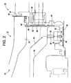
- FIG. 2 is a more detailed cross section of a portion of the bearing region in which embodiments of the present invention may be located.
- FIG. 1 a portion of a gas turbine 10, specifically, at a main or #1 bearing region of the gas turbine 10, in which embodiments of the present invention may be located.
- Embodiments of the present invention are not limited to a bearing region of a gas turbine.
- Embodiments of the present invention may be located in devices other than a gas turbine, wherein these other devices include a bearing region to be sealed in accordance with embodiments of the present invention.
- the main bearing region of the gas turbine 10 may include a rotor 14, a bearing housing 16 and bearing seals 18. Also included may be an inlet guide vane (IGV)shroud 24, a forward stub shaft (FSS) 30, and a gap or cavity 32 between the rotor 14 and a stator.
- IGV inlet guide vane
- FSS forward stub shaft
- the rotor 14 and stator may comprise other components in which a gap is located between these other components.
- a line with an arrowhead 34 shows a flow of bearing oil from the bearing housing 16 to a sump.
- Embodiments of the present invention effectively seal the bearing oil within the bearing housing 16 and prevent any leakage from the bearing housing 16, including into a main airflow path, which may cause issues with operation of the gas turbine 10.
- the one or more bearings within the bearing housing 16 may comprise vacuum-type bearings for the rotor 14, which are those where the bearing oil within the housing 16 is drained due to suction. That is, the sump is maintained at a pressure lower than the atmospheric pressure.
- FIG. 2 is shown a more detailed cross section the main or #1 bearing portion of the gas turbine 10 in which embodiments of the present invention may be located.
- a flow of ambient air as indicated by the line with an arrowhead 40 may come from the surrounding atmosphere of the gas turbine 10.
- the flow of ambient air 40 may then pass through a load tunnel compartment of the gas turbine 10 before getting into the main or #1 bearing region.
- the flow of ambient air 40 passes through holes 42, 44 formed in the bearing housing 16, in accordance with an embodiment of the present invention.
- the holes 42, 44 may be circular or any other suitable shape.
- the ambient airflow 40 then passes through the bearing seals 18, and a portion of the airflow 40 passes adjacent to a cover plate 46 or other suitable air directional device, according to an embodiment of the present invention.
- the ambient air flow 40 passing through the bearing seals 18 creates a relatively high pressure difference across the seals 18, which prevents the oil from leaking out from the bearing housing 16.
- the cover plate 46 may be fitted into a groove 48 formed in the IGV shroud 24 for attachment purposes. Other suitable methods of attaching the cover plate 46 in the desired location may be utilized. A portion of the cover plate 46 may be located adjacent to or abutting the bearing housing 16. The cover plate 46 may comprise nodular cast iron, sheet metal, or other suitable material.
- the flow of ambient air 40 then passes through the rotor-stator gap or cavity 32 before entering a main airflow path 50.
- the cover plate 46 blocks the flow of ambient air from flowing directly to the gap 32 between the rotor and stator.
- a flow of ambient air 40 is routed through the main or #1 bearing seals 18 and then through the rotor-stator (R0) gap 32.
- This provides for relatively effective #1 bearing oil sealing (i.e., primarily by the forward portion of the seals 18 in FIG. 2 ), thereby achieving a reduction in the amount of oil leakage from the bearing housing 16.
- the routing of the ambient air flow 40 in accordance with embodiments of the present invention reduces the amount of air leakage flow from the ambient air entering the holes 42, 44 in the bearing housing 16 and passing through the rotor-stator gap 32 and into the main airflow path 50.
- a greater amount of air leakage flow passing through the rotor-stator gap 32 and into the main airflow path 50 may disturb the flow of air in the main airflow path 50.
- the reduced amount of the flow of air 40 through the rotor-stator gap 32 and into the main airflow path 50 is still high enough to allow for purging of the rotor-stator gap or cavity 32, which is a desirable effect.
- Embodiments of the invention provide for one or more holes 42, 44 in the bearing housing 16. Also provided is a cover plate 46. This configuration of the holes 42, 44 ensures a relatively effective seal of the bearing #1 oil within the housing 16. Without the cover plate 46, a forward stub shaft (FSS) labyrinth seal 52 ( FIG. 1 ) is needed for restricting the flow to the rotor-stator gap 32. Adding a cover plate 46 eliminates the need for the use of a FSS labyrinth seal 52, with the bearing seal 18 aft portion taking care of any flow restriction.
- FSS forward stub shaft
- Embodiments of the invention provide for a relatively more effective oil sealing with a relatively higher delta P (i.e., higher air pressure difference) across the bearing seals 18 at the #1 bearing aft end.
- the overall oil sealing and air purging system of embodiments of the present invention is relatively more reliable, since the rotor surface is closed.
- the necessity for use of the forward stub shaft (FSS) labyrinth seal can be eliminated, thereby providing for cost saving and improved reliability.
- the amount of air flow into the main flow path 50 through the rotor-stator (R0) gap 32 may be reduced by a relatively significant amount at any given flow path pressure condition, thereby meeting certain aerodynamic requirements.
Landscapes
- Engineering & Computer Science (AREA)
- Mechanical Engineering (AREA)
- General Engineering & Computer Science (AREA)
- Chemical & Material Sciences (AREA)
- Combustion & Propulsion (AREA)
- Sealing Using Fluids, Sealing Without Contact, And Removal Of Oil (AREA)
- Turbine Rotor Nozzle Sealing (AREA)
- Sealing Of Bearings (AREA)
Abstract
Apparatus for sealing and purging a bearing region includes a bearing housing (16) having at least one hole (42, 44) that allows a flow of air to flow through the at least one hole (42, 44), and at least one bearing seal (18) that allows the flow of air to flow through the at least one bearing seal (18), thereby creating a pressure difference across the bearing seal (18). The apparatus also includes an air directional device (46) having at least a portion of the flow of air to flow adjacent to the air directional device (46), and a pair of components having a gap (32) between the pair of components that allows the at least a portion of the flow of air to flow through the gap (32), thereby purging the gap (32).
Description
- The subject matter disclosed herein relates to main bearings and, more particularly, to a sealing and purging arrangement at a main bearing region.
- A gas turbine includes a main rotor that requires sealing of the main bearing to prevent leakage of the bearing oil in the bearing housing or compartment. Such leakage may cause operational issues for the gas turbine. It is known to use labyrinth seals in the sealing of the bearing housing. However, these labyrinth seals oftentimes pose added cost and reliability issues.
- According to one aspect of the invention, apparatus for sealing and purging a bearing region includes a bearing housing having at least one hole that allows a flow of air to flow through the at least one hole, and at least one bearing seal that allows the flow of air to flow through the at least one bearing seal, thereby creating a pressure difference across the bearing seal. The apparatus also includes an air directional device having at least a portion of the flow of air to flow adjacent to the air directional device, and a pair of components having a gap between the pair of components that allows the at least a portion of the flow of air to flow through the gap, thereby purging the gap.
- According to another aspect of the invention, apparatus for sealing and purging a bearing region includes a bearing housing having at least one hole that allows a flow of air to flow through the at least one hole, and at least one bearing seal that allows the flow of air to flow through the at least one bearing seal, thereby creating a pressure difference across the bearing seal. The apparatus also includes an air directional device having at least a portion of the flow of air to flow adjacent to the air directional device, and a rotor and stator having a gap between the rotor and the stator that allows the at least a portion of the flow of air to flow through the gap, thereby purging the gap.
- According to yet another aspect of the invention, a method of sealing a bearing housing containing oil includes routing a flow of air through one or more holes located in the bearing housing, and routing the flow of air through at least one bearing seal, thereby creating a pressure difference across the bearing seal to seal the oil within the bearing housing. The method also includes routing at least a portion of the flow of air adjacent to an air directional device, and routing the at least a portion of the flow of air through a gap between a rotor and a stator, thereby purging the gap.
- These and other advantages and features will become more apparent from the following description taken in conjunction with the drawings.
- The subject matter, which is regarded as the invention, is particularly pointed out and distinctly claimed in the claims at the conclusion of the specification. The foregoing and other features and advantages of the invention are apparent from the following detailed description taken in conjunction with the accompanying drawings in which:
-
FIG. 1 is a cross section of a bearing region in which embodiments of the present invention may be located; and -
FIG. 2 is a more detailed cross section of a portion of the bearing region in which embodiments of the present invention may be located. - The detailed description explains embodiments of the invention, together with advantages and features, by way of example with reference to the drawings.
- In
FIG. 1 is shown a portion of agas turbine 10, specifically, at a main or #1 bearing region of thegas turbine 10, in which embodiments of the present invention may be located. Embodiments of the present invention are not limited to a bearing region of a gas turbine. Embodiments of the present invention may be located in devices other than a gas turbine, wherein these other devices include a bearing region to be sealed in accordance with embodiments of the present invention. The main bearing region of thegas turbine 10 may include arotor 14, a bearinghousing 16 andbearing seals 18. Also included may be an inlet guide vane (IGV)shroud 24, a forward stub shaft (FSS) 30, and a gap orcavity 32 between therotor 14 and a stator. In embodiments of the present invention located in devices other than a gas turbine, therotor 14 and stator may comprise other components in which a gap is located between these other components. A line with an arrowhead 34 shows a flow of bearing oil from the bearinghousing 16 to a sump. Embodiments of the present invention effectively seal the bearing oil within the bearinghousing 16 and prevent any leakage from the bearinghousing 16, including into a main airflow path, which may cause issues with operation of thegas turbine 10. The one or more bearings within the bearinghousing 16 may comprise vacuum-type bearings for therotor 14, which are those where the bearing oil within thehousing 16 is drained due to suction. That is, the sump is maintained at a pressure lower than the atmospheric pressure. - In
FIG. 2 is shown a more detailed cross section the main or #1 bearing portion of thegas turbine 10 in which embodiments of the present invention may be located. In an embodiment, a flow of ambient air as indicated by the line with anarrowhead 40 may come from the surrounding atmosphere of thegas turbine 10. The flow ofambient air 40 may then pass through a load tunnel compartment of thegas turbine 10 before getting into the main or #1 bearing region. There, the flow ofambient air 40 passes throughholes housing 16, in accordance with an embodiment of the present invention. Theholes ambient airflow 40 then passes through thebearing seals 18, and a portion of theairflow 40 passes adjacent to acover plate 46 or other suitable air directional device, according to an embodiment of the present invention. Theambient air flow 40 passing through thebearing seals 18 creates a relatively high pressure difference across theseals 18, which prevents the oil from leaking out from the bearinghousing 16. - The
cover plate 46 may be fitted into agroove 48 formed in theIGV shroud 24 for attachment purposes. Other suitable methods of attaching thecover plate 46 in the desired location may be utilized. A portion of thecover plate 46 may be located adjacent to or abutting the bearinghousing 16. Thecover plate 46 may comprise nodular cast iron, sheet metal, or other suitable material. The flow ofambient air 40 then passes through the rotor-stator gap orcavity 32 before entering amain airflow path 50. Thecover plate 46 blocks the flow of ambient air from flowing directly to thegap 32 between the rotor and stator. - In embodiments of the present invention, a flow of
ambient air 40 is routed through the main or #1 bearingseals 18 and then through the rotor-stator (R0)gap 32. This provides for relatively effective #1 bearing oil sealing (i.e., primarily by the forward portion of theseals 18 inFIG. 2 ), thereby achieving a reduction in the amount of oil leakage from the bearinghousing 16. In addition, the routing of theambient air flow 40 in accordance with embodiments of the present invention reduces the amount of air leakage flow from the ambient air entering theholes housing 16 and passing through the rotor-stator gap 32 and into themain airflow path 50. A greater amount of air leakage flow passing through the rotor-stator gap 32 and into themain airflow path 50 may disturb the flow of air in themain airflow path 50. At the same time, the reduced amount of the flow ofair 40 through the rotor-stator gap 32 and into themain airflow path 50 is still high enough to allow for purging of the rotor-stator gap orcavity 32, which is a desirable effect. - Embodiments of the invention provide for one or
more holes housing 16. Also provided is acover plate 46. This configuration of theholes housing 16. Without thecover plate 46, a forward stub shaft (FSS) labyrinth seal 52 (FIG. 1 ) is needed for restricting the flow to the rotor-stator gap 32. Adding acover plate 46 eliminates the need for the use of a FSS labyrinth seal 52, with thebearing seal 18 aft portion taking care of any flow restriction. Embodiments of the invention provide for a relatively more effective oil sealing with a relatively higher delta P (i.e., higher air pressure difference) across thebearing seals 18 at the #1 bearing aft end. Also, the overall oil sealing and air purging system of embodiments of the present invention is relatively more reliable, since the rotor surface is closed. As such, the necessity for use of the forward stub shaft (FSS) labyrinth seal can be eliminated, thereby providing for cost saving and improved reliability. Further, the amount of air flow into themain flow path 50 through the rotor-stator (R0)gap 32 may be reduced by a relatively significant amount at any given flow path pressure condition, thereby meeting certain aerodynamic requirements. - While the invention has been described in detail in connection with only a limited number of embodiments, it should be readily understood that the invention is not limited to such disclosed embodiments. Rather, the invention can be modified to incorporate any number of variations, alterations, substitutions or equivalent arrangements not heretofore described, but which are commensurate with the spirit and scope of the invention. Additionally, while various embodiments of the invention have been described, it is to be understood that aspects of the invention may include only some of the described embodiments.
For completeness, various aspects of the invention are now set out in the following numbered clauses: - 1. Apparatus for sealing and purging a bearing region, comprising:
- a bearing housing having at least one hole that allows a flow of air to flow through the at least one hole;
- at least one bearing seal that allows the flow of air to flow through the at least one bearing seal, thereby creating a pressure difference across the bearing seal;
- an air directional device having at least a portion of the flow of air to flow adjacent to the air directional device; and
- a pair of components having a gap between the pair of components that allows the at least a portion of the flow of air to flow through the gap, thereby purging the gap.
- 2. The apparatus of clause 1, wherein the air directional device comprises a surface that allows the at least a portion of the flow of air to flow adjacent to the surface.
- 3. The apparatus of clause 1, wherein the air directional device comprises a plate having a surface that allows the at least a portion of the flow of air to flow adjacent to the surface.
- 4. The apparatus of clause 1, wherein the bearing housing has a pair of holes that allow the flow of air to flow through the pair of holes and to the at least one bearing seal.
- 5. The apparatus of clause 1, wherein the flow of air comprises a flow of ambient air.
- 6. The apparatus of clause 1, wherein the air directional device blocks the flow of air from flowing directly to the gap.
- 7. The apparatus of clause 1, wherein the pair of components comprises a rotor and stator of a gas turbine.
- 8. Apparatus for sealing and purging a bearing region, comprising:
- a bearing housing having at least one hole that allows a flow of air to flow through the at least one hole;
- at least one bearing seal that allows the flow of air to flow through the at least one bearing seal, thereby creating a pressure difference across the bearing seal;
- an air directional device having at least a portion of the flow of air to flow adjacent to the air directional device; and
- a rotor and stator having a gap between the rotor and the stator that allows the at least a portion of the flow of air to flow through the gap, thereby purging the gap.
- 9. The apparatus of clause 8, wherein the air directional device comprises a surface that allows the at least a portion of the flow of air to flow adjacent to the surface.
- 10. The apparatus of clause 8, wherein the air directional device comprises a plate having a surface that allows the at least a portion of the flow of air to flow adjacent to the surface.
- 11. The apparatus of clause 8, wherein the bearing housing has a pair of holes that allow the flow of air to flow through the pair of holes and to the at least one bearing seal.
- 12. The apparatus of clause 8, wherein the flow of air comprises a flow of ambient air.
- 13. The apparatus of clause 8, wherein the air directional device blocks the flow of air from flowing directly to the gap.
- 14. The apparatus of clause 8, wherein the rotor and the stator comprise a portion of a gas turbine.
- 15. A method of sealing a bearing housing containing oil, the method comprising:
- routing a flow of air through one or more holes located in the bearing housing;
- routing the flow of air through at least one bearing seal, thereby creating a pressure difference across the bearing seal to seal the oil within the bearing housing;
- routing at least a portion of the flow of air adjacent to an air directional device; and
- routing the at least a portion of the flow of air through a gap between a rotor and a stator, thereby purging the gap.
- 16. The method of clause 15, wherein after routing the at least a portion of the flow of air through a gap between a rotor and a stator, further comprising routing the at least a portion of the flow of air into a main flow path.
- 17. The method of clause 15, wherein the routing a flow of air through one or more holes located in the bearing housing comprises routing the flow of air through a pair of holes located in the bearing housing.
- 18. The method of clause 15, wherein the routing a flow of air through one or more holes located in the bearing housing comprises routing the flow of air through the one or more holes and to the at least one bearing seal.
- 19. The method of clause 15, wherein the routing the flow of air through at least one bearing air seal comprises routing the flow of air through at least one bearing seal and routing the at least a portion of the flow of air adjacent to an air directional device.
- 20. The method of clause 15, further comprising the step of blocking the flow of air from flowing directly to the gap between the rotor and stator.
Claims (7)
- Apparatus for sealing and purging a bearing region, comprising:a bearing housing (16) having at least one hole (42, 44) that allows a flow of air to flow through the at least one hole (42, 44);at least one bearing seal (18) that allows the flow of air to flow through the at least one bearing seal (18), thereby creating a pressure difference across the bearing seal (18);an air directional device (46) having at least a portion of the flow of air to flow adjacent to the air directional device (46); anda pair of components having a gap (32) between the pair of components that allows the at least a portion of the flow of air to flow through the gap (32), thereby purging the gap (32).
- The apparatus of claim 1, wherein the air directional device (46) comprises a surface that allows the at least a portion of the flow of air to flow adjacent to the surface.
- The apparatus of claim 1 or claim 2, wherein the air directional device (46) comprises a plate having a surface that allows the at least a portion of the flow of air to flow adjacent to the surface.
- The apparatus of any preceding claim, wherein the bearing housing (16) has a pair of holes that allow the flow of air to flow through the pair of holes and to the at least one bearing seal (18).
- The apparatus of any preceding claim, wherein the flow of air comprises a flow of ambient air.
- The apparatus of any preceding claim, wherein the air directional device (46) blocks the flow of air from flowing directly to the gap (32).
- The apparatus of any preceding claim, wherein the pair of components comprises a rotor (14) and stator of a gas turbine (10).
Applications Claiming Priority (1)
| Application Number | Priority Date | Filing Date | Title |
|---|---|---|---|
| US12/652,165 US8529200B2 (en) | 2010-01-05 | 2010-01-05 | Sealing and purging arrangement for a main bearing region |
Publications (1)
| Publication Number | Publication Date |
|---|---|
| EP2354471A2 true EP2354471A2 (en) | 2011-08-10 |
Family
ID=43636267
Family Applications (1)
| Application Number | Title | Priority Date | Filing Date |
|---|---|---|---|
| EP10196266A Withdrawn EP2354471A2 (en) | 2010-01-05 | 2010-12-21 | Sealing and purging arrangement for a main bearing region |
Country Status (4)
| Country | Link |
|---|---|
| US (1) | US8529200B2 (en) |
| EP (1) | EP2354471A2 (en) |
| JP (1) | JP2011141029A (en) |
| CN (1) | CN102140937A (en) |
Families Citing this family (7)
| Publication number | Priority date | Publication date | Assignee | Title |
|---|---|---|---|---|
| WO2014079466A1 (en) * | 2012-11-21 | 2014-05-30 | Volvo Truck Corporation | Power turbine unit |
| US9617916B2 (en) | 2012-11-28 | 2017-04-11 | Pratt & Whitney Canada Corp. | Gas turbine engine with bearing buffer air flow and method |
| KR101327861B1 (en) | 2013-06-28 | 2013-11-11 | 조정봉 | Oil deflector |
| DE102014117840A1 (en) * | 2014-12-04 | 2016-06-09 | Rolls-Royce Deutschland Ltd & Co Kg | Device having a rotationally fixed first component and a second component rotatably connected at least in regions to the first component |
| DE102014117841A1 (en) | 2014-12-04 | 2016-06-09 | Rolls-Royce Deutschland Ltd & Co Kg | Device having a rotationally fixed first component and a second component rotatably connected at least in regions to the first component |
| US10520035B2 (en) | 2016-11-04 | 2019-12-31 | United Technologies Corporation | Variable volume bearing compartment |
| CN112833190B (en) * | 2020-12-28 | 2022-07-19 | 东方电气集团东方汽轮机有限公司 | Rotary mechanical sealing system suitable for high-density and high-viscosity working medium |
Family Cites Families (10)
| Publication number | Priority date | Publication date | Assignee | Title |
|---|---|---|---|---|
| DE2625551A1 (en) * | 1976-06-05 | 1977-12-15 | Motoren Turbinen Union | DEVICE FOR SEALING THE STORAGE CHAMBER OF A TURBO MACHINE, IN PARTICULAR A GAS TURBINE ENGINE |
| US5344160A (en) * | 1992-12-07 | 1994-09-06 | General Electric Company | Shaft sealing of steam turbines |
| US5480232A (en) * | 1994-05-26 | 1996-01-02 | General Electric Co. | Oil seal for gas turbine |
| JP3310909B2 (en) * | 1997-07-08 | 2002-08-05 | 三菱重工業株式会社 | Gas turbine vane sealing device |
| US6266954B1 (en) * | 1999-12-15 | 2001-07-31 | General Electric Co. | Double wall bearing cone |
| JP4091874B2 (en) * | 2003-05-21 | 2008-05-28 | 本田技研工業株式会社 | Secondary air supply device for gas turbine engine |
| US20050206088A1 (en) * | 2004-03-16 | 2005-09-22 | Anderson James H | Bearing seal with backup device |
| JP4773804B2 (en) * | 2005-11-17 | 2011-09-14 | 三菱重工業株式会社 | gas turbine |
| CN101600854A (en) * | 2006-09-14 | 2009-12-09 | 索拉透平公司 | Seal structure for turbine engine |
| US8167534B2 (en) * | 2006-09-14 | 2012-05-01 | Solar Turbines Inc. | Seal for a turbine engine |
-
2010
- 2010-01-05 US US12/652,165 patent/US8529200B2/en not_active Expired - Fee Related
- 2010-12-21 EP EP10196266A patent/EP2354471A2/en not_active Withdrawn
- 2010-12-27 JP JP2010289139A patent/JP2011141029A/en not_active Withdrawn
-
2011
- 2011-01-05 CN CN2011100099367A patent/CN102140937A/en active Pending
Non-Patent Citations (1)
| Title |
|---|
| None |
Also Published As
| Publication number | Publication date |
|---|---|
| US20110164964A1 (en) | 2011-07-07 |
| JP2011141029A (en) | 2011-07-21 |
| CN102140937A (en) | 2011-08-03 |
| US8529200B2 (en) | 2013-09-10 |
Similar Documents
| Publication | Publication Date | Title |
|---|---|---|
| EP2354471A2 (en) | Sealing and purging arrangement for a main bearing region | |
| US9316118B2 (en) | Bearing chamber apparatus | |
| US8257017B2 (en) | Method and device for cooling a component of a turbine | |
| US10323656B2 (en) | Extracting dry gas from a wet-gas compressor | |
| US20190085768A1 (en) | Bearing structure for turbocharger and turbocharger | |
| US20140219777A1 (en) | Turbocharger | |
| US20100192571A1 (en) | Turbocharger Having a Turbocharger Housing | |
| ITFI20130204A1 (en) | "FAN-COOLED ELECTRICAL MACHINE WITH AXIAL THRUST COMPENSATION" | |
| US20090050410A1 (en) | Methods and systems for sealing rotating machines | |
| EP3406862B1 (en) | A seal assembly and method for reducing aircraft engine oil leakage | |
| US10844742B2 (en) | Heat shield | |
| CN105899763A (en) | Turbomachine bearing housing | |
| EP1840384A2 (en) | Centrifugal fan | |
| CN106661942B (en) | Turbine element including auxiliary sealing device and the method for testing the element | |
| JP5175161B2 (en) | Bearing device with bearing oil leakage prevention mechanism | |
| KR101779880B1 (en) | Bearing housing of an exhaust-gas turbocharger | |
| BR112013012889B1 (en) | oil evacuation device and turbomachinery comprising such a device | |
| EP2650485A2 (en) | Shaft sealing system for steam turbines | |
| EP2835544A2 (en) | Bearing cage deflector | |
| CN106884722B (en) | A kind of flow path designs method for bearing bore oil seal | |
| CN100458242C (en) | Structure to prevent water ingress and oil leakage in turbine oil | |
| US20140248125A1 (en) | Chamber fluid removal system | |
| JP2012112359A (en) | Bearing stand cover of axial-flow exhaust turbine and axial-flow exhaust turbine | |
| JP2016037960A (en) | Shaft seal system and exhaust gas turbocharger | |
| CN110296100A (en) | Turbo-compressor |
Legal Events
| Date | Code | Title | Description |
|---|---|---|---|
| PUAI | Public reference made under article 153(3) epc to a published international application that has entered the european phase |
Free format text: ORIGINAL CODE: 0009012 |
|
| AK | Designated contracting states |
Kind code of ref document: A2 Designated state(s): AL AT BE BG CH CY CZ DE DK EE ES FI FR GB GR HR HU IE IS IT LI LT LU LV MC MK MT NL NO PL PT RO RS SE SI SK SM TR |
|
| AX | Request for extension of the european patent |
Extension state: BA ME |
|
| STAA | Information on the status of an ep patent application or granted ep patent |
Free format text: STATUS: THE APPLICATION IS DEEMED TO BE WITHDRAWN |
|
| 18D | Application deemed to be withdrawn |
Effective date: 20140701 |