EP2354460A1 - Turbine Guide Vane - Google Patents
Turbine Guide Vane Download PDFInfo
- Publication number
- EP2354460A1 EP2354460A1 EP10152535A EP10152535A EP2354460A1 EP 2354460 A1 EP2354460 A1 EP 2354460A1 EP 10152535 A EP10152535 A EP 10152535A EP 10152535 A EP10152535 A EP 10152535A EP 2354460 A1 EP2354460 A1 EP 2354460A1
- Authority
- EP
- European Patent Office
- Prior art keywords
- guide vane
- pads
- rail
- rails
- blades
- Prior art date
- Legal status (The legal status is an assumption and is not a legal conclusion. Google has not performed a legal analysis and makes no representation as to the accuracy of the status listed.)
- Granted
Links
Images


Classifications
-
- F—MECHANICAL ENGINEERING; LIGHTING; HEATING; WEAPONS; BLASTING
- F01—MACHINES OR ENGINES IN GENERAL; ENGINE PLANTS IN GENERAL; STEAM ENGINES
- F01D—NON-POSITIVE DISPLACEMENT MACHINES OR ENGINES, e.g. STEAM TURBINES
- F01D9/00—Stators
- F01D9/02—Nozzles; Nozzle boxes; Stator blades; Guide conduits, e.g. individual nozzles
- F01D9/04—Nozzles; Nozzle boxes; Stator blades; Guide conduits, e.g. individual nozzles forming ring or sector
- F01D9/042—Nozzles; Nozzle boxes; Stator blades; Guide conduits, e.g. individual nozzles forming ring or sector fixing blades to stators
-
- F—MECHANICAL ENGINEERING; LIGHTING; HEATING; WEAPONS; BLASTING
- F01—MACHINES OR ENGINES IN GENERAL; ENGINE PLANTS IN GENERAL; STEAM ENGINES
- F01D—NON-POSITIVE DISPLACEMENT MACHINES OR ENGINES, e.g. STEAM TURBINES
- F01D25/00—Component parts, details, or accessories, not provided for in, or of interest apart from, other groups
- F01D25/24—Casings; Casing parts, e.g. diaphragms, casing fastenings
- F01D25/246—Fastening of diaphragms or stator-rings
-
- F—MECHANICAL ENGINEERING; LIGHTING; HEATING; WEAPONS; BLASTING
- F05—INDEXING SCHEMES RELATING TO ENGINES OR PUMPS IN VARIOUS SUBCLASSES OF CLASSES F01-F04
- F05D—INDEXING SCHEME FOR ASPECTS RELATING TO NON-POSITIVE-DISPLACEMENT MACHINES OR ENGINES, GAS-TURBINES OR JET-PROPULSION PLANTS
- F05D2230/00—Manufacture
- F05D2230/60—Assembly methods
- F05D2230/64—Assembly methods using positioning or alignment devices for aligning or centring, e.g. pins
-
- F—MECHANICAL ENGINEERING; LIGHTING; HEATING; WEAPONS; BLASTING
- F05—INDEXING SCHEMES RELATING TO ENGINES OR PUMPS IN VARIOUS SUBCLASSES OF CLASSES F01-F04
- F05D—INDEXING SCHEME FOR ASPECTS RELATING TO NON-POSITIVE-DISPLACEMENT MACHINES OR ENGINES, GAS-TURBINES OR JET-PROPULSION PLANTS
- F05D2240/00—Components
- F05D2240/80—Platforms for stationary or moving blades
Definitions
- the present invention relates to a turbine guide vane.
- the present invention refers to a supporting system for turbine guide vanes.
- Gas turbine guide vanes are known to comprise a platform from which one or also more than one guide vane blade extend.
- each platform two or also three guide vane blades extend.
- the platforms have a front rail and a rear rail arranged to be inserted into guide vane carrier seats having a slot shape.
- the shape of the rails must allow free deformations in order to avoid stress concentration and breakage risk.
- Figure 1 shows a first embodiment of a traditional rail 1 inserted into a guide vane carrier seat 2 (in this figure the dimensions are exaggerated for sake of clarity, particularly radial dimensions are exaggerated); moreover, figure 1 also shows in dashed line a portion of a guide vane blade 3.
- the rail 1 has a pad 4, extending from its side towards the guide vane blades 3, resting against the guide vane carrier seat 2; a second pad 5 extends from the side of the rail 1 opposite the guide vane blade 3 and rests against the guide vane carrier seat 2.
- the guide vane in this traditional embodiment proved to have good deformation properties and also easy of assembling (i.e. sliding of the rail 1 into the guide vane carrier seat 2 proved to be easy); nevertheless this structure can only be implemented in lighter guide vanes; i.e. typically in guide vanes having only one or two guide vane blades 3.
- Figure 2 shows a different embodiment of traditional rails.
- This rail 1 is provided with pads 6 extending from the same side being the side of the rail 1 towards the guide vane blade 3; the opposite side of the rail 1 has no pads and rests directly against the guide vane carrier seat 2.
- the guide vanes with these rails can be much heavier than those with the rails of figure 1 , for example these guide vanes can have three or also more than three guide vane blades.
- the technical aim of the present invention is therefore to provide a guide vane by which the said problems of the known art are eliminated.
- an aspect of the invention is to provide a guide vane that can have a substantial weight and, in this respect, can also have three or more than three guide vane blades.
- Another aspect of the invention is to provide a guide vane with rails having large deformation possibilities, such that during operation stress and forces concentration are avoided or limited and the lifetime of the guide vanes is increased.
- a further aspect of the present invention is to provide a guide vane that can be easily and quickly assembled and disassembled.
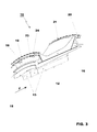
- the guide vane 10 has a platform 12 from which guide vane blades 13 extend; in particular figure 3 shows an embodiment of a guide vane 10 with three guide vane blades 13, it is anyhow clear that in different embodiments their number can also be different.
- the guide vane 10 is also provided with supporting means that are located at the front side and rear side of the platform 12 (with reference to the hot gas flow direction indicated by arrow F in figure 3 ).
- the front side of the platform 12 has a seat 15 for the stator heat shield and, correspondingly, the rear side of the platform 12 has a seat 16 for a further stator heat shield (the stator heat shields are not shown).
- the front side of the platform 12 has a rail 18 arranged to be housed into a guide vane carrier seat 19; the guide vane carrier seat 19 is of traditional type and have the shape of a circumferential slot.
- the rear side of the platform 12 has a rail 20 arranged to be housed into a guide vane carrier seat 21; also the guide vane carrier seat 21 is of traditional type and have the shape of a circumferential slot.
- the rails 18 and 20 have projecting pads arranged to rest against the guide vane carrier seats 19, 21.
- each rail 18, 20 has two pads 23 extending from one side of the rail and two further pads 24 extending from an opposite side of the rail 18, 20.
- the pads 23 and 24 extend from opposite radial sides of each rail 18, 20; the pads 23 extend from a side of the rails 18, 20 facing the guide vane blades 13, and the other pads 24 extend from the opposite side, i.e. from the side opposite the guide vane blades 13.
- the pads 23 and 24 extend from opposite circumferential portions 26 of the rails 18, 20, i.e. they are located close to the circumferentially opposite ends of the rails 18, 20.
- the pads 23, 24 that extend from the same circumferential portion 26 of the rails 18, 20 are advantageously at least partly staggered with respect to one another.
- figure 4 (referring to the front rail 18) shows the pads 23 and 24 that are staggered but are circumferentially very close one to the other.
- Figure 5 shows that the pads 23 and 24 that are staggered are also circumferentially distant one from the other.
- each couple of pads 23, 24 extending from the same circumferential portion 26 of each rail 18, 20 the pads 23 extending from the side of the rail facing the guide vane blades 13 are farther from the respective rail end 27 than those opposite the guide vanes blades 13 (i.e. the pads 24).
- the pads 23 and 24 are symmetrically disposed with respect to the vane axis 28; it is anyhow clear that in different embodiments the pads 23 and 24 are not symmetrically disposed with respect to the vane axis 28.
- the guide vanes of the invention may also have a heavy structure (such as for example guide vanes having three or more guide vane blades 13), since assembling/disassembling is easy and the degree of allowable deformations is very large.
Landscapes
- Engineering & Computer Science (AREA)
- Mechanical Engineering (AREA)
- General Engineering & Computer Science (AREA)
- Turbine Rotor Nozzle Sealing (AREA)
Abstract
Description
- The present invention relates to a turbine guide vane.
- In particular the present invention refers to a supporting system for turbine guide vanes.
- Gas turbine guide vanes are known to comprise a platform from which one or also more than one guide vane blade extend.
- For example, in guide vanes of the third or fourth stage, from each platform two or also three guide vane blades extend.
- The platforms have a front rail and a rear rail arranged to be inserted into guide vane carrier seats having a slot shape.
- When in operation, mechanical forces and thermally induced deformations highly stress the guide vane rails and the guide vane carriers.
- For this reason, the shape of the rails must allow free deformations in order to avoid stress concentration and breakage risk.
-
Figure 1 shows a first embodiment of atraditional rail 1 inserted into a guide vane carrier seat 2 (in this figure the dimensions are exaggerated for sake of clarity, particularly radial dimensions are exaggerated); moreover,figure 1 also shows in dashed line a portion of aguide vane blade 3. - The
rail 1 has apad 4, extending from its side towards theguide vane blades 3, resting against the guidevane carrier seat 2; asecond pad 5 extends from the side of therail 1 opposite theguide vane blade 3 and rests against the guidevane carrier seat 2. - The guide vane in this traditional embodiment proved to have good deformation properties and also easy of assembling (i.e. sliding of the
rail 1 into the guidevane carrier seat 2 proved to be easy); nevertheless this structure can only be implemented in lighter guide vanes; i.e. typically in guide vanes having only one or twoguide vane blades 3. -
Figure 2 shows a different embodiment of traditional rails. - This
rail 1 is provided withpads 6 extending from the same side being the side of therail 1 towards theguide vane blade 3; the opposite side of therail 1 has no pads and rests directly against the guidevane carrier seat 2. - The guide vanes with these rails can be much heavier than those with the rails of
figure 1 , for example these guide vanes can have three or also more than three guide vane blades. - Nevertheless these guide vanes have limited freedom of deformation; this could cause during operation stress and forces concentration and consequently possibility of structural breakages.
- In addition, assembling (i.e. sliding the rails of these guide vanes into the corresponding guide vane carrier seats 2) and disassembling (i.e. sliding the rails out of the guide vane carrier seats 2) proved to be very difficult, because of the weight of these guide vanes and the large surfaces of the rails and guide vane carrier seats that are directly in contact with one another.
- The technical aim of the present invention is therefore to provide a guide vane by which the said problems of the known art are eliminated.
- Within the scope of this technical aim, an aspect of the invention is to provide a guide vane that can have a substantial weight and, in this respect, can also have three or more than three guide vane blades.
- Another aspect of the invention is to provide a guide vane with rails having large deformation possibilities, such that during operation stress and forces concentration are avoided or limited and the lifetime of the guide vanes is increased.
- A further aspect of the present invention is to provide a guide vane that can be easily and quickly assembled and disassembled.
- The technical aim, together with these and further aspects, are attained according to the invention by providing a guide vane in accordance with the accompanying claims.
- Further characteristics and advantages of the invention will be more apparent from the description of a preferred but non-exclusive embodiment of the guide vane according to the invention, illustrated by way of nonlimiting example in the accompanying drawings, in which:
-
Figures 1 and 2 are two different embodiments of rails of a guide vane of the prior art; -
Figure 3 is a side view of a guide vane in an embodiment of the invention; and -
Figure 4 and 5 are views respectively of a front rail and rear rail of the guide vanes; in these figures the dimensions (in particular radial dimensions) are exaggerated for clarity. - With reference to
figures 3-5 , these show a turbine guide vane indicated by thereference 10. - The guide vane 10 has a
platform 12 from whichguide vane blades 13 extend; in particularfigure 3 shows an embodiment of aguide vane 10 with threeguide vane blades 13, it is anyhow clear that in different embodiments their number can also be different. - The
guide vane 10 is also provided with supporting means that are located at the front side and rear side of the platform 12 (with reference to the hot gas flow direction indicated by arrow F infigure 3 ). - In particular, the front side of the
platform 12 has aseat 15 for the stator heat shield and, correspondingly, the rear side of theplatform 12 has aseat 16 for a further stator heat shield (the stator heat shields are not shown). - In addition, the front side of the
platform 12 has arail 18 arranged to be housed into a guidevane carrier seat 19; the guidevane carrier seat 19 is of traditional type and have the shape of a circumferential slot. - Similarly, the rear side of the
platform 12 has arail 20 arranged to be housed into a guidevane carrier seat 21; also the guidevane carrier seat 21 is of traditional type and have the shape of a circumferential slot. - The
rails vane carrier seats - Advantageously, each
rail pads 23 extending from one side of the rail and twofurther pads 24 extending from an opposite side of therail - In particular, as shown in the enclosed figures, the
pads rail pads 23 extend from a side of therails guide vane blades 13, and theother pads 24 extend from the opposite side, i.e. from the side opposite theguide vane blades 13. - In addition, the
pads circumferential portions 26 of therails rails - The
pads circumferential portion 26 of therails - In this respect
figure 4 (referring to the front rail 18) shows thepads -
Figure 5 (referring to the rear rail 20) shows that thepads - In addition, in each couple of
pads circumferential portion 26 of eachrail pads 23 extending from the side of the rail facing theguide vane blades 13 are farther from therespective rail end 27 than those opposite the guide vanes blades 13 (i.e. the pads 24). - In a particular embodiment the
pads vane axis 28; it is anyhow clear that in different embodiments thepads vane axis 28. - Assembling of the guide vanes of the invention is quite easy and fast, because the
rails vane carriers seats - Since the contact occurs only between the
pads vane carrier seat rails vane carrier seats pads 24 and the same guidevane carrier seats seats - Also disassembling is easy and quick; in fact since there are no large contact surfaces between the
rails vane carrier seats rails vane carrier seats - In addition, the guide vanes of the invention may also have a heavy structure (such as for example guide vanes having three or more guide vane blades 13), since assembling/disassembling is easy and the degree of allowable deformations is very large.
- In fact, when the guide vanes 18, 20 are assembled within the guide
vane carrier seats - Naturally the features described may be independently provided from one another.
- In practice the materials used and the dimensions are chosen according to requirements and to the state of the art.
-
- 1
- rail
- 2
- guide vane carrier seat
- 3
- guide vane blade
- 4
- pad
- 5
- pad
- 6
- pad
-
- 10
- guide vane
- 12
- platform
- 13
- guide vane blades
- 15, 16
- seat for the stator heat shield
- 18
- front rail
- 19
- guide vane carrier seat of 18
- 20
- rear rail
- 21
- guide vane carrier seat of 20
- 23
- pad
- 24
- pad
- 26
- portion of 18, 20
- 27
- rail end
- 28
- guide vane axis
- F
- flow gas direction
Claims (11)
- Guide vane (10) of a gas turbine comprising a platform (12) from which at least a guide vane blade (13) extends, said platform (12) having a front rail (18) and a rear rail (20) arranged to be housed in guide vane carrier seats (19, 21), wherein said front and rear rails (18, 20) have projecting pads (23, 24) arranged to rest against the guide vane carrier seats (19, 21), characterised in that said front and rear rails (18, 20) have at least two pads (23) extending from one side of the front and rear rails (18, 20) and at least two further pads (24) extending from an opposite side of the front and rear rails (18, 20).
- Guide vane (10) as claimed in claim 1, characterised in that said pads (23, 24) extend from opposite radial sides of said front and rear rails (18, 20).
- Guide vane (10) as claimed in claim 2, characterised in that said pads (23, 24) extend from a side of the front and rear rails (18, 20) facing the guide vane blade (13), and from the opposite side being opposite the guide vane blades (13).
- Guide vane (10) as claimed in claim 1, characterised in that said pads (23, 24) extend from opposite circumferential portions (26) of the front and rear rails (18, 20).
- Guide vane (10) as claimed in claim 4, characterised in that said pads (23, 24) extending from the same circumferential portion (26) of the front and rear rails (18, 20) are at least partly staggered with respect to one another.
- Guide vane (10) as claimed in claim 5, characterised in that in each couple of pads (23, 24) extending at the same circumferential portion (26) of each front and rear rail (18, 20), the pads (23) extending from the side of the front and rear rails (18, 20) facing the guide vane blades (13) are farther from the respective rail end (27) than those opposite the guide vanes blades (13).
- Guide vane (10) as claimed in claim 1, characterised in that said pads (23, 24) are symmetrically disposed with respect to a guide vane axis (28).
- Guide vane (10) as claimed in claim 1, characterised in that said pads (23, 24) are not symmetrically disposed with respect to a guide vane axis (28).
- Guide vane (10) as claimed in claim 1, characterised by comprising a plurality of guide vane blades (13).
- Guide vane (10) as claimed in claim 9, characterised in that said plurality of guide vane blades (13) comprises at least three guide vane blades (13).
- Guide vane (10) as claimed in claim 1, characterised in that when the rails (18, 20) are housed in the guide vane carrier seats (19, 21) a gap between the pads (23, 24) and the same guide vane carrier seats (19, 21) is provided
Priority Applications (4)
| Application Number | Priority Date | Filing Date | Title |
|---|---|---|---|
| EP10152535.0A EP2354460B1 (en) | 2010-02-03 | 2010-02-03 | Turbine Guide Vane |
| ES10152535T ES2431290T3 (en) | 2010-02-03 | 2010-02-03 | Turbine guide blade |
| US13/012,317 US20110189002A1 (en) | 2010-02-03 | 2011-01-24 | Turbine guide vane |
| MYPI2011000407A MY155452A (en) | 2010-02-03 | 2011-01-28 | Turbine guide vane |
Applications Claiming Priority (1)
| Application Number | Priority Date | Filing Date | Title |
|---|---|---|---|
| EP10152535.0A EP2354460B1 (en) | 2010-02-03 | 2010-02-03 | Turbine Guide Vane |
Publications (2)
| Publication Number | Publication Date |
|---|---|
| EP2354460A1 true EP2354460A1 (en) | 2011-08-10 |
| EP2354460B1 EP2354460B1 (en) | 2013-07-24 |
Family
ID=42235861
Family Applications (1)
| Application Number | Title | Priority Date | Filing Date |
|---|---|---|---|
| EP10152535.0A Active EP2354460B1 (en) | 2010-02-03 | 2010-02-03 | Turbine Guide Vane |
Country Status (4)
| Country | Link |
|---|---|
| US (1) | US20110189002A1 (en) |
| EP (1) | EP2354460B1 (en) |
| ES (1) | ES2431290T3 (en) |
| MY (1) | MY155452A (en) |
Cited By (2)
| Publication number | Priority date | Publication date | Assignee | Title |
|---|---|---|---|---|
| EP3034798A1 (en) * | 2014-12-18 | 2016-06-22 | Alstom Technology Ltd | Gas turbine vane |
| EP3147457A1 (en) * | 2015-09-22 | 2017-03-29 | General Electric Technology GmbH | Gas turbine vane |
Families Citing this family (2)
| Publication number | Priority date | Publication date | Assignee | Title |
|---|---|---|---|---|
| US9303528B2 (en) | 2012-07-06 | 2016-04-05 | United Technologies Corporation | Mid-turbine frame thermal radiation shield |
| US9151226B2 (en) | 2012-07-06 | 2015-10-06 | United Technologies Corporation | Corrugated mid-turbine frame thermal radiation shield |
Citations (3)
| Publication number | Priority date | Publication date | Assignee | Title |
|---|---|---|---|---|
| DE1476928A1 (en) * | 1965-05-29 | 1969-07-31 | Bergmann Borsig Veb | Guide vane root for turbines with high inlet temperature |
| US5205708A (en) * | 1992-02-07 | 1993-04-27 | General Electric Company | High pressure turbine component interference fit up |
| US7458772B2 (en) * | 2004-10-26 | 2008-12-02 | Alstom Technology Ltd. | Guide vane ring of a turbomachine and associated modification method |
Family Cites Families (1)
| Publication number | Priority date | Publication date | Assignee | Title |
|---|---|---|---|---|
| FR2923527B1 (en) * | 2007-11-13 | 2013-12-27 | Snecma | STAGE OF TURBINE OR COMPRESSOR, IN PARTICULAR TURBOMACHINE |
-
2010
- 2010-02-03 EP EP10152535.0A patent/EP2354460B1/en active Active
- 2010-02-03 ES ES10152535T patent/ES2431290T3/en active Active
-
2011
- 2011-01-24 US US13/012,317 patent/US20110189002A1/en not_active Abandoned
- 2011-01-28 MY MYPI2011000407A patent/MY155452A/en unknown
Patent Citations (3)
| Publication number | Priority date | Publication date | Assignee | Title |
|---|---|---|---|---|
| DE1476928A1 (en) * | 1965-05-29 | 1969-07-31 | Bergmann Borsig Veb | Guide vane root for turbines with high inlet temperature |
| US5205708A (en) * | 1992-02-07 | 1993-04-27 | General Electric Company | High pressure turbine component interference fit up |
| US7458772B2 (en) * | 2004-10-26 | 2008-12-02 | Alstom Technology Ltd. | Guide vane ring of a turbomachine and associated modification method |
Cited By (4)
| Publication number | Priority date | Publication date | Assignee | Title |
|---|---|---|---|---|
| EP3034798A1 (en) * | 2014-12-18 | 2016-06-22 | Alstom Technology Ltd | Gas turbine vane |
| US10221709B2 (en) | 2014-12-18 | 2019-03-05 | Ansaldo Energia Switzerland AG | Gas turbine vane |
| EP3147457A1 (en) * | 2015-09-22 | 2017-03-29 | General Electric Technology GmbH | Gas turbine vane |
| US10731490B2 (en) | 2015-09-22 | 2020-08-04 | Ansaldo Energia Switzerland AG | Gas turbine vane |
Also Published As
| Publication number | Publication date |
|---|---|
| ES2431290T3 (en) | 2013-11-25 |
| EP2354460B1 (en) | 2013-07-24 |
| US20110189002A1 (en) | 2011-08-04 |
| MY155452A (en) | 2015-10-15 |
Similar Documents
| Publication | Publication Date | Title |
|---|---|---|
| JP6310958B2 (en) | Shroud holding system with holding spring | |
| EP2586980A2 (en) | Turbine blade rail damper | |
| JP6085561B2 (en) | Non-rotating shroud for turbine engine | |
| EP2354460B1 (en) | Turbine Guide Vane | |
| CN106321170B (en) | Shroud retention system with keyed retention clips | |
| JP6183990B2 (en) | Gas turbine frame reinforcement rail | |
| EP1939411B1 (en) | Cantilevered nozzle with crowned flange to improve outer band low cycle fatigue | |
| EP2357322A2 (en) | Mounting apparatus for low-ductility turbine shroud | |
| EP2402557B1 (en) | Turbine rotor assembly | |
| US8353672B2 (en) | Turbine blade damper arrangement | |
| CN102748136A (en) | Apparatus to seal with a turbine blade stage in a gas turbine | |
| KR20060067864A (en) | Turbocharger | |
| US8684665B2 (en) | Ring sector of turbomachine turbine | |
| JP5478613B2 (en) | Turbomachine fan rotor | |
| KR20110102908A (en) | Turbine wheel with system for supporting blades axially | |
| CN102392692A (en) | Apparatus and system for sealing a turbine rotor | |
| US8967968B2 (en) | Turbine rotor blade | |
| EP3070274A1 (en) | Turbine blade assembly with cooled platform | |
| US9494039B2 (en) | Stationary gas turbine arrangement and method for performing maintenance work | |
| KR102261350B1 (en) | Methods and systems for securing turbine nozzles | |
| CN103362575B (en) | Collateral support turbine case | |
| EP2602548A1 (en) | Leaf spring damper for a turbine engine fuel delivery system | |
| RU2547354C2 (en) | Cooling of gas turbine structural element, say, rotor disc or turbine blade | |
| EP2895697B1 (en) | Turbine airfoil platform rail with gusset | |
| CN106988785B (en) | Gas turbine guide vane |
Legal Events
| Date | Code | Title | Description |
|---|---|---|---|
| PUAI | Public reference made under article 153(3) epc to a published international application that has entered the european phase |
Free format text: ORIGINAL CODE: 0009012 |
|
| AK | Designated contracting states |
Kind code of ref document: A1 Designated state(s): AT BE BG CH CY CZ DE DK EE ES FI FR GB GR HR HU IE IS IT LI LT LU LV MC MK MT NL NO PL PT RO SE SI SK SM TR |
|
| AX | Request for extension of the european patent |
Extension state: AL BA RS |
|
| 17P | Request for examination filed |
Effective date: 20120202 |
|
| 17Q | First examination report despatched |
Effective date: 20120514 |
|
| GRAP | Despatch of communication of intention to grant a patent |
Free format text: ORIGINAL CODE: EPIDOSNIGR1 |
|
| GRAS | Grant fee paid |
Free format text: ORIGINAL CODE: EPIDOSNIGR3 |
|
| GRAA | (expected) grant |
Free format text: ORIGINAL CODE: 0009210 |
|
| AK | Designated contracting states |
Kind code of ref document: B1 Designated state(s): AT BE BG CH CY CZ DE DK EE ES FI FR GB GR HR HU IE IS IT LI LT LU LV MC MK MT NL NO PL PT RO SE SI SK SM TR |
|
| REG | Reference to a national code |
Ref country code: GB Ref legal event code: FG4D |
|
| REG | Reference to a national code |
Ref country code: CH Ref legal event code: EP |
|
| REG | Reference to a national code |
Ref country code: AT Ref legal event code: REF Ref document number: 623594 Country of ref document: AT Kind code of ref document: T Effective date: 20130815 |
|
| REG | Reference to a national code |
Ref country code: IE Ref legal event code: FG4D |
|
| REG | Reference to a national code |
Ref country code: DE Ref legal event code: R096 Ref document number: 602010008758 Country of ref document: DE Effective date: 20130919 |
|
| REG | Reference to a national code |
Ref country code: NL Ref legal event code: T3 |
|
| REG | Reference to a national code |
Ref country code: ES Ref legal event code: FG2A Ref document number: 2431290 Country of ref document: ES Kind code of ref document: T3 Effective date: 20131125 |
|
| REG | Reference to a national code |
Ref country code: AT Ref legal event code: MK05 Ref document number: 623594 Country of ref document: AT Kind code of ref document: T Effective date: 20130724 |
|
| REG | Reference to a national code |
Ref country code: LT Ref legal event code: MG4D |
|
| PG25 | Lapsed in a contracting state [announced via postgrant information from national office to epo] |
Ref country code: LT Free format text: LAPSE BECAUSE OF FAILURE TO SUBMIT A TRANSLATION OF THE DESCRIPTION OR TO PAY THE FEE WITHIN THE PRESCRIBED TIME-LIMIT Effective date: 20130724 Ref country code: PT Free format text: LAPSE BECAUSE OF FAILURE TO SUBMIT A TRANSLATION OF THE DESCRIPTION OR TO PAY THE FEE WITHIN THE PRESCRIBED TIME-LIMIT Effective date: 20131125 Ref country code: HR Free format text: LAPSE BECAUSE OF FAILURE TO SUBMIT A TRANSLATION OF THE DESCRIPTION OR TO PAY THE FEE WITHIN THE PRESCRIBED TIME-LIMIT Effective date: 20130724 Ref country code: AT Free format text: LAPSE BECAUSE OF FAILURE TO SUBMIT A TRANSLATION OF THE DESCRIPTION OR TO PAY THE FEE WITHIN THE PRESCRIBED TIME-LIMIT Effective date: 20130724 Ref country code: BE Free format text: LAPSE BECAUSE OF FAILURE TO SUBMIT A TRANSLATION OF THE DESCRIPTION OR TO PAY THE FEE WITHIN THE PRESCRIBED TIME-LIMIT Effective date: 20130724 Ref country code: SE Free format text: LAPSE BECAUSE OF FAILURE TO SUBMIT A TRANSLATION OF THE DESCRIPTION OR TO PAY THE FEE WITHIN THE PRESCRIBED TIME-LIMIT Effective date: 20130724 Ref country code: NO Free format text: LAPSE BECAUSE OF FAILURE TO SUBMIT A TRANSLATION OF THE DESCRIPTION OR TO PAY THE FEE WITHIN THE PRESCRIBED TIME-LIMIT Effective date: 20131024 Ref country code: CY Free format text: LAPSE BECAUSE OF FAILURE TO SUBMIT A TRANSLATION OF THE DESCRIPTION OR TO PAY THE FEE WITHIN THE PRESCRIBED TIME-LIMIT Effective date: 20130626 Ref country code: IS Free format text: LAPSE BECAUSE OF FAILURE TO SUBMIT A TRANSLATION OF THE DESCRIPTION OR TO PAY THE FEE WITHIN THE PRESCRIBED TIME-LIMIT Effective date: 20131124 |
|
| PG25 | Lapsed in a contracting state [announced via postgrant information from national office to epo] |
Ref country code: LV Free format text: LAPSE BECAUSE OF FAILURE TO SUBMIT A TRANSLATION OF THE DESCRIPTION OR TO PAY THE FEE WITHIN THE PRESCRIBED TIME-LIMIT Effective date: 20130724 Ref country code: SI Free format text: LAPSE BECAUSE OF FAILURE TO SUBMIT A TRANSLATION OF THE DESCRIPTION OR TO PAY THE FEE WITHIN THE PRESCRIBED TIME-LIMIT Effective date: 20130724 Ref country code: GR Free format text: LAPSE BECAUSE OF FAILURE TO SUBMIT A TRANSLATION OF THE DESCRIPTION OR TO PAY THE FEE WITHIN THE PRESCRIBED TIME-LIMIT Effective date: 20131025 Ref country code: PL Free format text: LAPSE BECAUSE OF FAILURE TO SUBMIT A TRANSLATION OF THE DESCRIPTION OR TO PAY THE FEE WITHIN THE PRESCRIBED TIME-LIMIT Effective date: 20130724 Ref country code: FI Free format text: LAPSE BECAUSE OF FAILURE TO SUBMIT A TRANSLATION OF THE DESCRIPTION OR TO PAY THE FEE WITHIN THE PRESCRIBED TIME-LIMIT Effective date: 20130724 |
|
| PG25 | Lapsed in a contracting state [announced via postgrant information from national office to epo] |
Ref country code: CY Free format text: LAPSE BECAUSE OF FAILURE TO SUBMIT A TRANSLATION OF THE DESCRIPTION OR TO PAY THE FEE WITHIN THE PRESCRIBED TIME-LIMIT Effective date: 20130724 |
|
| PG25 | Lapsed in a contracting state [announced via postgrant information from national office to epo] |
Ref country code: CZ Free format text: LAPSE BECAUSE OF FAILURE TO SUBMIT A TRANSLATION OF THE DESCRIPTION OR TO PAY THE FEE WITHIN THE PRESCRIBED TIME-LIMIT Effective date: 20130724 Ref country code: SK Free format text: LAPSE BECAUSE OF FAILURE TO SUBMIT A TRANSLATION OF THE DESCRIPTION OR TO PAY THE FEE WITHIN THE PRESCRIBED TIME-LIMIT Effective date: 20130724 Ref country code: EE Free format text: LAPSE BECAUSE OF FAILURE TO SUBMIT A TRANSLATION OF THE DESCRIPTION OR TO PAY THE FEE WITHIN THE PRESCRIBED TIME-LIMIT Effective date: 20130724 Ref country code: DK Free format text: LAPSE BECAUSE OF FAILURE TO SUBMIT A TRANSLATION OF THE DESCRIPTION OR TO PAY THE FEE WITHIN THE PRESCRIBED TIME-LIMIT Effective date: 20130724 Ref country code: RO Free format text: LAPSE BECAUSE OF FAILURE TO SUBMIT A TRANSLATION OF THE DESCRIPTION OR TO PAY THE FEE WITHIN THE PRESCRIBED TIME-LIMIT Effective date: 20130724 |
|
| PLBE | No opposition filed within time limit |
Free format text: ORIGINAL CODE: 0009261 |
|
| STAA | Information on the status of an ep patent application or granted ep patent |
Free format text: STATUS: NO OPPOSITION FILED WITHIN TIME LIMIT |
|
| 26N | No opposition filed |
Effective date: 20140425 |
|
| REG | Reference to a national code |
Ref country code: DE Ref legal event code: R097 Ref document number: 602010008758 Country of ref document: DE Effective date: 20140425 |
|
| PG25 | Lapsed in a contracting state [announced via postgrant information from national office to epo] |
Ref country code: LU Free format text: LAPSE BECAUSE OF FAILURE TO SUBMIT A TRANSLATION OF THE DESCRIPTION OR TO PAY THE FEE WITHIN THE PRESCRIBED TIME-LIMIT Effective date: 20140203 Ref country code: MC Free format text: LAPSE BECAUSE OF FAILURE TO SUBMIT A TRANSLATION OF THE DESCRIPTION OR TO PAY THE FEE WITHIN THE PRESCRIBED TIME-LIMIT Effective date: 20130724 |
|
| REG | Reference to a national code |
Ref country code: IE Ref legal event code: MM4A |
|
| PG25 | Lapsed in a contracting state [announced via postgrant information from national office to epo] |
Ref country code: IE Free format text: LAPSE BECAUSE OF NON-PAYMENT OF DUE FEES Effective date: 20140203 |
|
| REG | Reference to a national code |
Ref country code: FR Ref legal event code: PLFP Year of fee payment: 7 |
|
| PG25 | Lapsed in a contracting state [announced via postgrant information from national office to epo] |
Ref country code: MT Free format text: LAPSE BECAUSE OF FAILURE TO SUBMIT A TRANSLATION OF THE DESCRIPTION OR TO PAY THE FEE WITHIN THE PRESCRIBED TIME-LIMIT Effective date: 20130724 |
|
| PG25 | Lapsed in a contracting state [announced via postgrant information from national office to epo] |
Ref country code: SM Free format text: LAPSE BECAUSE OF FAILURE TO SUBMIT A TRANSLATION OF THE DESCRIPTION OR TO PAY THE FEE WITHIN THE PRESCRIBED TIME-LIMIT Effective date: 20130724 |
|
| PG25 | Lapsed in a contracting state [announced via postgrant information from national office to epo] |
Ref country code: BG Free format text: LAPSE BECAUSE OF FAILURE TO SUBMIT A TRANSLATION OF THE DESCRIPTION OR TO PAY THE FEE WITHIN THE PRESCRIBED TIME-LIMIT Effective date: 20130724 |
|
| REG | Reference to a national code |
Ref country code: CH Ref legal event code: PFA Owner name: GENERAL ELECTRIC TECHNOLOGY GMBH, CH Free format text: FORMER OWNER: ALSTOM TECHNOLOGY LTD, CH |
|
| PG25 | Lapsed in a contracting state [announced via postgrant information from national office to epo] |
Ref country code: HU Free format text: LAPSE BECAUSE OF FAILURE TO SUBMIT A TRANSLATION OF THE DESCRIPTION OR TO PAY THE FEE WITHIN THE PRESCRIBED TIME-LIMIT; INVALID AB INITIO Effective date: 20100203 Ref country code: TR Free format text: LAPSE BECAUSE OF FAILURE TO SUBMIT A TRANSLATION OF THE DESCRIPTION OR TO PAY THE FEE WITHIN THE PRESCRIBED TIME-LIMIT Effective date: 20130724 |
|
| REG | Reference to a national code |
Ref country code: DE Ref legal event code: R081 Ref document number: 602010008758 Country of ref document: DE Owner name: GENERAL ELECTRIC TECHNOLOGY GMBH, CH Free format text: FORMER OWNER: ALSTOM TECHNOLOGY LTD., BADEN, CH Ref country code: DE Ref legal event code: R081 Ref document number: 602010008758 Country of ref document: DE Owner name: ANSALDO ENERGIA IP UK LIMITED, GB Free format text: FORMER OWNER: ALSTOM TECHNOLOGY LTD., BADEN, CH |
|
| REG | Reference to a national code |
Ref country code: ES Ref legal event code: PC2A Owner name: GENERAL ELECTRIC TECHNOLOGY GMBH Effective date: 20161021 |
|
| REG | Reference to a national code |
Ref country code: NL Ref legal event code: HC Owner name: GENERAL ELECTRIC TECHNOLOGY GMBH; CH Free format text: DETAILS ASSIGNMENT: VERANDERING VAN EIGENAAR(S), VERANDERING VAN NAAM VAN DE EIGENAAR(S); FORMER OWNER NAME: ALSTOM TECHNOLOGY LTD Effective date: 20161006 |
|
| REG | Reference to a national code |
Ref country code: FR Ref legal event code: CD Owner name: ALSTOM TECHNOLOGY LTD, CH Effective date: 20161110 |
|
| REG | Reference to a national code |
Ref country code: FR Ref legal event code: PLFP Year of fee payment: 8 |
|
| REG | Reference to a national code |
Ref country code: CH Ref legal event code: PUE Owner name: ANSALDO ENERGIA IP UK LIMITED, GB Free format text: FORMER OWNER: GENERAL ELECTRIC TECHNOLOGY GMBH, CH |
|
| REG | Reference to a national code |
Ref country code: NL Ref legal event code: PD Owner name: ANSALDO ENERGIA IP UK LIMITED; GB Free format text: DETAILS ASSIGNMENT: CHANGE OF OWNER(S), ASSIGNMENT; FORMER OWNER NAME: GENERAL ELECTRIC TECHNOLOGY GMBH Effective date: 20170301 |
|
| PGFP | Annual fee paid to national office [announced via postgrant information from national office to epo] |
Ref country code: CH Payment date: 20170217 Year of fee payment: 8 |
|
| PGFP | Annual fee paid to national office [announced via postgrant information from national office to epo] |
Ref country code: NL Payment date: 20170216 Year of fee payment: 8 Ref country code: GB Payment date: 20170216 Year of fee payment: 8 |
|
| PGFP | Annual fee paid to national office [announced via postgrant information from national office to epo] |
Ref country code: ES Payment date: 20170213 Year of fee payment: 8 |
|
| REG | Reference to a national code |
Ref country code: DE Ref legal event code: R081 Ref document number: 602010008758 Country of ref document: DE Owner name: ANSALDO ENERGIA IP UK LIMITED, GB Free format text: FORMER OWNER: GENERAL ELECTRIC TECHNOLOGY GMBH, BADEN, CH |
|
| REG | Reference to a national code |
Ref country code: GB Ref legal event code: 732E Free format text: REGISTERED BETWEEN 20170824 AND 20170830 |
|
| REG | Reference to a national code |
Ref country code: ES Ref legal event code: PC2A Owner name: ANSALDO ENERGIA IP UK LIMITED Effective date: 20170927 |
|
| REG | Reference to a national code |
Ref country code: FR Ref legal event code: TP Owner name: ANSALDO ENERGIA IP UK LIMITED, GB Effective date: 20171221 |
|
| REG | Reference to a national code |
Ref country code: FR Ref legal event code: PLFP Year of fee payment: 9 |
|
| PGFP | Annual fee paid to national office [announced via postgrant information from national office to epo] |
Ref country code: FR Payment date: 20180223 Year of fee payment: 9 |
|
| PG25 | Lapsed in a contracting state [announced via postgrant information from national office to epo] |
Ref country code: MK Free format text: LAPSE BECAUSE OF FAILURE TO SUBMIT A TRANSLATION OF THE DESCRIPTION OR TO PAY THE FEE WITHIN THE PRESCRIBED TIME-LIMIT Effective date: 20130724 |
|
| REG | Reference to a national code |
Ref country code: CH Ref legal event code: PL |
|
| REG | Reference to a national code |
Ref country code: NL Ref legal event code: MM Effective date: 20180301 |
|
| GBPC | Gb: european patent ceased through non-payment of renewal fee |
Effective date: 20180203 |
|
| PG25 | Lapsed in a contracting state [announced via postgrant information from national office to epo] |
Ref country code: CH Free format text: LAPSE BECAUSE OF NON-PAYMENT OF DUE FEES Effective date: 20180228 Ref country code: LI Free format text: LAPSE BECAUSE OF NON-PAYMENT OF DUE FEES Effective date: 20180228 |
|
| PG25 | Lapsed in a contracting state [announced via postgrant information from national office to epo] |
Ref country code: NL Free format text: LAPSE BECAUSE OF NON-PAYMENT OF DUE FEES Effective date: 20180301 |
|
| PG25 | Lapsed in a contracting state [announced via postgrant information from national office to epo] |
Ref country code: GB Free format text: LAPSE BECAUSE OF NON-PAYMENT OF DUE FEES Effective date: 20180203 |
|
| REG | Reference to a national code |
Ref country code: ES Ref legal event code: FD2A Effective date: 20190801 |
|
| PG25 | Lapsed in a contracting state [announced via postgrant information from national office to epo] |
Ref country code: ES Free format text: LAPSE BECAUSE OF NON-PAYMENT OF DUE FEES Effective date: 20180204 |
|
| PG25 | Lapsed in a contracting state [announced via postgrant information from national office to epo] |
Ref country code: FR Free format text: LAPSE BECAUSE OF NON-PAYMENT OF DUE FEES Effective date: 20190228 |
|
| P01 | Opt-out of the competence of the unified patent court (upc) registered |
Effective date: 20240430 |
|
| PGFP | Annual fee paid to national office [announced via postgrant information from national office to epo] |
Ref country code: DE Payment date: 20260217 Year of fee payment: 17 |
|
| PGFP | Annual fee paid to national office [announced via postgrant information from national office to epo] |
Ref country code: IT Payment date: 20260227 Year of fee payment: 17 |