EP2354088A1 - Hydrogen generator using steam-reforming reaction - Google Patents
Hydrogen generator using steam-reforming reaction Download PDFInfo
- Publication number
- EP2354088A1 EP2354088A1 EP11153711A EP11153711A EP2354088A1 EP 2354088 A1 EP2354088 A1 EP 2354088A1 EP 11153711 A EP11153711 A EP 11153711A EP 11153711 A EP11153711 A EP 11153711A EP 2354088 A1 EP2354088 A1 EP 2354088A1
- Authority
- EP
- European Patent Office
- Prior art keywords
- exhaust gas
- hydrogen generator
- steam
- hydrogen
- orifices
- Prior art date
- Legal status (The legal status is an assumption and is not a legal conclusion. Google has not performed a legal analysis and makes no representation as to the accuracy of the status listed.)
- Granted
Links
Images

Classifications
-
- C—CHEMISTRY; METALLURGY
- C01—INORGANIC CHEMISTRY
- C01B—NON-METALLIC ELEMENTS; COMPOUNDS THEREOF; METALLOIDS OR COMPOUNDS THEREOF NOT COVERED BY SUBCLASS C01C
- C01B3/00—Hydrogen; Gaseous mixtures containing hydrogen; Separation of hydrogen from mixtures containing it; Purification of hydrogen; Reversible storage of hydrogen
- C01B3/02—Production of hydrogen; Production of gaseous mixtures containing hydrogen
- C01B3/32—Production of hydrogen; Production of gaseous mixtures containing hydrogen by reaction of gaseous or liquid organic compounds with gasifying agents, e.g. water, carbon dioxide or air
- C01B3/34—Production of hydrogen; Production of gaseous mixtures containing hydrogen by reaction of gaseous or liquid organic compounds with gasifying agents, e.g. water, carbon dioxide or air by reaction of hydrocarbons with gasifying agents
- C01B3/38—Production of hydrogen; Production of gaseous mixtures containing hydrogen by reaction of gaseous or liquid organic compounds with gasifying agents, e.g. water, carbon dioxide or air by reaction of hydrocarbons with gasifying agents using catalysts
- C01B3/384—Production of hydrogen; Production of gaseous mixtures containing hydrogen by reaction of gaseous or liquid organic compounds with gasifying agents, e.g. water, carbon dioxide or air by reaction of hydrocarbons with gasifying agents using catalysts with external heating of the catalyst
-
- B—PERFORMING OPERATIONS; TRANSPORTING
- B01—PHYSICAL OR CHEMICAL PROCESSES OR APPARATUS IN GENERAL
- B01J—CHEMICAL OR PHYSICAL PROCESSES, e.g. CATALYSIS OR COLLOID CHEMISTRY; THEIR RELEVANT APPARATUS
- B01J8/00—Chemical or physical processes in general, conducted in the presence of fluids and solid particles; Apparatus for such processes
- B01J8/02—Chemical or physical processes in general, conducted in the presence of fluids and solid particles; Apparatus for such processes with stationary particles, e.g. in fixed beds
- B01J8/06—Chemical or physical processes in general, conducted in the presence of fluids and solid particles; Apparatus for such processes with stationary particles, e.g. in fixed beds in tube reactors; the solid particles being arranged in tubes
- B01J8/067—Heating or cooling the reactor
-
- B—PERFORMING OPERATIONS; TRANSPORTING
- B01—PHYSICAL OR CHEMICAL PROCESSES OR APPARATUS IN GENERAL
- B01J—CHEMICAL OR PHYSICAL PROCESSES, e.g. CATALYSIS OR COLLOID CHEMISTRY; THEIR RELEVANT APPARATUS
- B01J2208/00—Processes carried out in the presence of solid particles; Reactors therefor
- B01J2208/00008—Controlling the process
- B01J2208/00017—Controlling the temperature
- B01J2208/00106—Controlling the temperature by indirect heat exchange
- B01J2208/00168—Controlling the temperature by indirect heat exchange with heat exchange elements outside the bed of solid particles
- B01J2208/00212—Plates; Jackets; Cylinders
- B01J2208/00221—Plates; Jackets; Cylinders comprising baffles for guiding the flow of the heat exchange medium
-
- B—PERFORMING OPERATIONS; TRANSPORTING
- B01—PHYSICAL OR CHEMICAL PROCESSES OR APPARATUS IN GENERAL
- B01J—CHEMICAL OR PHYSICAL PROCESSES, e.g. CATALYSIS OR COLLOID CHEMISTRY; THEIR RELEVANT APPARATUS
- B01J2208/00—Processes carried out in the presence of solid particles; Reactors therefor
- B01J2208/00008—Controlling the process
- B01J2208/00017—Controlling the temperature
- B01J2208/00504—Controlling the temperature by means of a burner
-
- C—CHEMISTRY; METALLURGY
- C01—INORGANIC CHEMISTRY
- C01B—NON-METALLIC ELEMENTS; COMPOUNDS THEREOF; METALLOIDS OR COMPOUNDS THEREOF NOT COVERED BY SUBCLASS C01C
- C01B2203/00—Integrated processes for the production of hydrogen or synthesis gas
- C01B2203/02—Processes for making hydrogen or synthesis gas
- C01B2203/0205—Processes for making hydrogen or synthesis gas containing a reforming step
- C01B2203/0227—Processes for making hydrogen or synthesis gas containing a reforming step containing a catalytic reforming step
- C01B2203/0233—Processes for making hydrogen or synthesis gas containing a reforming step containing a catalytic reforming step the reforming step being a steam reforming step
-
- C—CHEMISTRY; METALLURGY
- C01—INORGANIC CHEMISTRY
- C01B—NON-METALLIC ELEMENTS; COMPOUNDS THEREOF; METALLOIDS OR COMPOUNDS THEREOF NOT COVERED BY SUBCLASS C01C
- C01B2203/00—Integrated processes for the production of hydrogen or synthesis gas
- C01B2203/08—Methods of heating or cooling
- C01B2203/0805—Methods of heating the process for making hydrogen or synthesis gas
- C01B2203/0811—Methods of heating the process for making hydrogen or synthesis gas by combustion of fuel
- C01B2203/0816—Heating by flames
Definitions
- the present invention relates to a hydrogen generator using a steam-reforming reaction, and, more particularly, to a heat exchanger-integrated hydrogen generator for producing hydrogen by a steam-reforming reaction using hydrocarbons as a raw material, in which a pressure loss induction structure for artificially reducing the pressure of exhaust gas is provided between a combustion unit and a exhaust gas discharge pipe, thus improving the uneven heat transfer of the exhaust gas supplied to reactor tubes.
- a fuel cell is an electrical generating system for simultaneously generating electricity and heat by converting chemical energy into electric energy by the electrochemical reaction of hydrogen and oxygen.
- hydrocarbons such as natural gas, liquefied petroleum gas (LPG), naphtha, gasoline, kerosene and the like, can be used as the raw material of a steam-reforming reaction. Further, the steam-reforming reaction is conducted at high temperature in the presence of a catalyst.
- LPG liquefied petroleum gas
- the inside of a hydrogen generator was divided into two regions, and then one region was used as a steam-reforming region (steam-reforming unit), and the other region was used as a combustion region (combustion unit) for generating the heat necessary for a steam-reforming reaction.
- the catalyst of the steam-reforming unit is mostly located in a catalytic reactor tube having a small diameter, and several catalytic reactor tubes are symmetrically disposed around a heat source depending on the capacity and size of a hydrogen generator.
- the heat generated from the combustion unit is transferred to the catalytic reactor tube by the radiation or convection of exhaust gas, and is then used in a steam-reforming reaction.
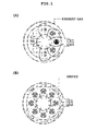
- a pressure loss induction structure for inducing exhaust gas in all directions and an exhaust gas collector is provided at the front end of an exhaust gas outlet, and, as shown in (B) of FIG. 1 , a structure for evenly discharging exhaust gas in all directions is required.
- the present invention has been devised to solve the above-mentioned problems attributable to the uneven flow of exhaust gas, and an object of the present invention intends to prevent reactions from being insufficiently conducted in a reactor for lack of heat by supplying an equal amount of heat to each reactor tube.
- the present invention intends to provide a hydrogen generator having a pressure loss induction structure, by which exhaust gas is evenly distributed and discharged in all directions by an arbitrarily formed partition wall and orifices before the exhaust gas starts from a combustor and then reaches an exhaust gas discharge pipe, so that heat is supplied to all the catalyst tubes in the same amount as a set value, and the hydrogen generator can be easily manufactured and installed and can be stably operated in spite of the thermal deformation attributable to high-temperature exhaust gas.
- An aspect of the present invention provides a cylindrical hydrogen generator for producing hydrogen by steam-reforming hydrocarbon materials, including: a reforming unit including a plurality of reactor tubes, each being filled with a catalyst; a combustion unit including a heat source for generating the heat necessary for a steam-reforming reaction in the reactor tubes; and a partition wall radially provided therein with orifices such that exhaust gas can be evenly distributed in all directions by artificially inducing the exhaust gas generated from the combustion unit and artificially regulating the pressure of the exhaust gas between the combustion unit and an exhaust gas discharge pipe.
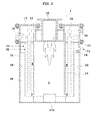
- FIG. 2 is a sectional view showing a conventional hydrogen generator which is applied to the present invention.
- the conventional hydrogen generator is a heat exchanger-integrated hydrogen generator including reactor tubes, each being filled with a catalyst, a combustion unit and the like.
- the present invention relates to a cylindrical hydrogen generator including: a combustion unit; and a reforming unit including two or more tubular reformers supplied with the heat necessary for a steam-reforming reaction by the exhaust gas generated from the combustion unit.
- the present invention provides a cylindrical hydrogen generator having a pressure loss induction structure in which an exhaust gas collecting passage communicating with an exhaust gas discharge pipe is formed by a partition wall along the inner circumference of the cylindrical hydrogen generator, and orifices are radially formed in the partition wall at regular intervals such that exhaust gas is evenly transferred to the exhaust gas collecting passage.
- FIG. 3 is a schematic sectional view showing a hydrogen generator having a pressure loss induction structure according to an embodiment of the present invention. As shown in FIG. 3 , this hydrogen generator is provided with a partition wall and orifices for pressure regulation such that exhaust gas is discharged in all directions.
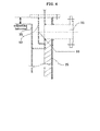
- FIG. 4 is a sectional view showing a pressure loss induction structure according to another embodiment of the present invention. As shown in FIG. 4 , this pressure loss induction structure is configured such that the cross-sectional area of an exhaust gas passage can be controlled by adjusting the length thereof or providing orifices.
- the hydrogen generator 1 which is a basis of the present invention, largely includes a combustion unit 2 provided with a heat source 10, and a reforming unit 3 for reforming hydrocarbon materials using steam.
- a burner is used as the heat source 10 provided in the combustion unit 2, but the present invention is not limited thereto. That is, all kinds of heating devices used to generate the heat necessary for a steam-reforming reaction can be used as the heat source 10.
- the hydrogen generator 1 is provided with the heat source 10 serving to generate the heat necessary for a steam-reforming reaction, and a fireproof material 13 is disposed around the heat source 10, so that high-temperature flames do not directly come into contact with the metal materials constituting the hydrogen generator 1 and simultaneously heat loss is minimized, thereby increasing the efficiency of the hydrogen generator 1.
- the hydrogen generator 1 including the fireproof material 13 is provided therein with flame guides 14, and the flame guides 14 divide the inside ofthe hydrogen generator 1 to form the combustion unit 2 for generating the heat necessary for a steam-reforming reaction.
- the exhaust gas generated from the combustion unit 2 flows into the reforming unit 3 to transfer the heat necessary for the steam-reforming reaction to the reforming unit 3.
- the reforming unit 3 which is formed by dividing the inside of the hydrogen generator 1 using the flame guides 14, is provided therein with a plurality of reactor tubes 20 filled with a catalyst. Hydrocarbon materials are steam-reformed by the action of the catalysts charged in the reactor tubes 20 to produce hydrogen.
- Each of the reactor tubes 20 has a cylindrical shape, and its inside is divided into three parts. It is shown in the drawings that each of the reactor tubes 20 is disposed in the reforming unit 3 using an upper connecting plate 21, but the present invention is not limited thereto.
- reactor tubes 20 are cylindrically disposed around the heat source 10 such that heat is efficiently used in a minimum of space.
- the hydrogen generator 1 is entirely surrounded by an outer case 15 to protect the hydrogen generator 1 from the external environment.
- the inner wall ofthe external case 15 is provided with an insulating material 16, thus preventing heat loss.
- the top and bottom of the hydrogen generator 1 is surrounded by an upper cover 17 and a lower cover 17a, respectively.
- a dispensing unit for supplying raw materials to the reactor tubes 20 and discharging the hydrogen produced by a steam-reforming reaction is provided under the upper cover 17.
- the dispensing unit includes raw material dispensers 18 and reformed gas dispensers 19.
- Each of the raw material dispensers 18 has a passage through which hydrocarbon materials can move such that the hydrocarbon materials are supplied to the rector tube 20, and each of the reformed gas dispensers 19 has a passage through which hydrogen can move such that the hydrogen produced by a steam-reforming reaction can be easily discharged to the places requiring hydrogen.
- hydrocarbon materials are supplied to each of the reactor tubes 20 by the raw material dispenser 18, and the heat generated from the heat source 10 provided in the combustion unit 2 is supplied to the reforming unit 3, thus causing mutual heat exchange.
- a pressure loss induction unit 32 and 33 is provided in order to allow exhaust gas to evenly transfer heat to each of the reactor tubes 20 and in order to evenly discharge exhaust gas to the outside.
- the exhaust gas produced from the combustion unit 2 is discharged to the outside through an exhaust gas discharge pipe 31.
- the pressure loss induction unit including a partition wall 32 and orifices 33 is provided, the exhaust gas is evenly discharged in all directions, not unevenly discharged in a direction toward the exhaust gas discharge pipe 31.
- the exhaust gas is collected in an exhaust gas collecting passage 34 and then discharged.
- the partition wall 32 may be formed by extending the outer wall of the insulating material 16 provided in the hydrogen generator 1.
- the exhaust gas collecting passage 34 is formed by the partition wall 32 and communicates with the exhaust gas discharge pipe.
- the exhaust gas collecting passage 34 is configured such that a single space is formed along the circumference ofthe hydrogen generator ofthe present invention.
- the orifices 33 are formed in the partition wall 32. As shown in (B) of FIG. 1 that is a plan view, the orifices 33 are radially arranged by perforating the partition wall 32 at regular intervals such that exhaust gas is evenly introduced into the exhaust gas collecting passage 34. If necessary, the number of the orifices 33 may be changed. Further, as shown in (B) of FIG. 1 , the orifices 33 may be formed between regions of the partition wall 32 that directly face the tubular reactors.
- the direct discharge of exhaust gas, causing the uneven flow of the exhaust gas used as a heat source in the reforming unit 3, can be prevented by means of the partition wall 32 in which the orifices 33 are formed.
- the orifices 33 also allow the exhaust gas, introduced into the exhaust gas collecting passage 34 as a single communicating passage by the orifices 33, to be easily transferred to the exhaust gas discharge pipe 31.
- the pressure loss induction structure may be provided by adjusting the length of the flame guide 14 disposed between the combustion unit 2 and the heat transfer unit 4 or by forming orifices in the flame guide 14 and thus adjusting the area of an exhaust gas passage.
- the pressure loss induction structure in which orifices are provided between the heat transfer unit 4 and the exhaust gas discharge pipe 31 will be described.
- the pressure loss structure may be realized by controlling a dimension of the space between the orifices 33 or the partition wall 32 and an outer wall.
- the pressure loss structure may be configured such that the guide wall 35 is additionally provided, and thus the exhaust gas passes through the guide wall 35 before it flows into the orifice 33.
- the guide wall 35 as shown in FIG. 4 , may be formed by extending the outer wall of the insulating material 16 surrounding the combustion unit 2.
- the pressure loss structure of the present invention must be easily fabricated and disposed, must not be influenced by the thermal deformation attributable to high-temperature operation, and must not influence the pressure loss structure to support the entire reactor structure.
- the degree of the pressure loss of exhaust gas must be determined in consideration of the pressure of fuel supplied to the burner and the loss of pressure in the heat exchanger.
- an exhaust gas collecting passage is provided between a combustion unit and an exhaust gas discharge pipe, and a partition wall is provided with an orifice, so that the discharge pressure of exhaust gas is artificially reduced, with the result that the exhaust gas is evenly distributed to reactor tubes cylindrically disposed around a heat source.
- the pressure loss structure according to the present invention can be easily fabricated and disposed and is configured such that its performance is not influenced by the thermal deformation attributable to high-temperature operation, the productivity of hydrogen and the convenience of a hydrogen generator can be maintained even when the hydrogen generator has been used for a long time.
Landscapes
- Chemical & Material Sciences (AREA)
- Chemical Kinetics & Catalysis (AREA)
- Organic Chemistry (AREA)
- Health & Medical Sciences (AREA)
- General Health & Medical Sciences (AREA)
- Engineering & Computer Science (AREA)
- Combustion & Propulsion (AREA)
- Inorganic Chemistry (AREA)
- Hydrogen, Water And Hydrids (AREA)
Abstract
Description
- This application claims the benefit of Korean Patent Application No.
10-2010-0011911, filed February 9th 2010 - The present invention relates to a hydrogen generator using a steam-reforming reaction, and, more particularly, to a heat exchanger-integrated hydrogen generator for producing hydrogen by a steam-reforming reaction using hydrocarbons as a raw material, in which a pressure loss induction structure for artificially reducing the pressure of exhaust gas is provided between a combustion unit and a exhaust gas discharge pipe, thus improving the uneven heat transfer of the exhaust gas supplied to reactor tubes.
- Generally, a fuel cell is an electrical generating system for simultaneously generating electricity and heat by converting chemical energy into electric energy by the electrochemical reaction of hydrogen and oxygen.
- It is predicted that such a fuel cell will replace an internal combustion engine because it has excellent energy efficiency. Therefore, in the near future, the stable supply of hydrogen will be an essential factor in the use of a fuel cell as a future source of alternative energy.
- As methods of supplying hydrogen to a fuel cell, a method of producing hydrogen by electrolyzing water and a method of producing hydrogen by steam-reforming a hydrogencontaining raw material are used.
- In this case, all kinds of hydrocarbons, such as natural gas, liquefied petroleum gas (LPG), naphtha, gasoline, kerosene and the like, can be used as the raw material of a steam-reforming reaction. Further, the steam-reforming reaction is conducted at high temperature in the presence of a catalyst.
- Therefore, there must be a catalyst in the place in which a steam-reforming reaction takes place, and the heat necessary for the steam-reforming reaction must be supplied thereto.
- Conventionally, in order to supply the heat necessary for a steam-reforming reaction, a method of burning fuel to generate heat and then transferring the heat to a hydrogen generator has been used. However, this method is problematic in that efficiency is decreased because heat loss occurs due to the increase in size of an apparatus and the transfer of high-temperature exhaust gas.
- Recently, in order to solve the above problem, the inside of a hydrogen generator was divided into two regions, and then one region was used as a steam-reforming region (steam-reforming unit), and the other region was used as a combustion region (combustion unit) for generating the heat necessary for a steam-reforming reaction.
- In this case, the catalyst of the steam-reforming unit is mostly located in a catalytic reactor tube having a small diameter, and several catalytic reactor tubes are symmetrically disposed around a heat source depending on the capacity and size of a hydrogen generator.
- Further, the heat generated from the combustion unit is transferred to the catalytic reactor tube by the radiation or convection of exhaust gas, and is then used in a steam-reforming reaction.
- However, in the heat transfer using exhaust gas, heat cannot be evenly transferred to the catalytic reactor tube because exhaust gas flows unevenly, so that the catalytic reactor tubes are not sufficiently supplied with heat, with the result that a steam-reforming reaction cannot be conducted easily, thereby deteriorating the total performance and efficiency of a reactor. This phenomenon will be described in detail as follows.
- Generally, in order to improve thermal efficiency, high-temperature exhaust gas undergoes an exhaust gas recovery process using a heat exchanger several times even after it is discharged from a reformer. For this purpose, exhaust gas gathers at an outlet and is then transferred to a heat exchanger. In this case, exhaust gas moves along the shortest path between a combustor and an outlet. Therefore, as shown in (A) of
FIG. 1 , a reactor tube which is located relatively far from an outlet does not frequently come into contact with exhaust gas, and thus the amount of the heat transferred from the exhaust gas to the reactor tube decreases. - In order to solve the above problem, a pressure loss induction structure for inducing exhaust gas in all directions and an exhaust gas collector is provided at the front end of an exhaust gas outlet, and, as shown in (B) of
FIG. 1 , a structure for evenly discharging exhaust gas in all directions is required. - When heat is unevenly supplied to reactor tubes due to the uneven flow of exhaust gas, there are the following problems. First, when the temperature of some of the reactor tubes does not reach the target temperature, the steam-reforming reaction in the relevant reactor tubes is conducted to a degree lower than the designed value, so that the production of hydrogen decreases and the concentration of unreacted methane in a product increases, thereby directly decreasing the efficiency of a hydrogen generator and increasing the cost for separating a hydrogen purifier necessarily provided at the rear end of a hydrogen generator. Second, when exhaust gas flows unevenly, some of reactor tubes may be heated above their set value, and, when they are exposed to high temperature for a long period of time, a reactor is damaged by the creep of the material of the reactor or by the corrosion of the metal attributable to reformed gas, with the result that the durability of a hydrogen generator decreases. As described above, the uneven distribution of exhaust gas causes the problems of the efficiency of a hydrogen generator being decreased at low temperature and the durability thereof being deteriorated at high temperature. These problems must be solved in order to improve the performance of a hydrogen generator.
- Accordingly, the present invention has been devised to solve the above-mentioned problems attributable to the uneven flow of exhaust gas, and an object of the present invention intends to prevent reactions from being insufficiently conducted in a reactor for lack of heat by supplying an equal amount of heat to each reactor tube.
- Concretely, the present invention intends to provide a hydrogen generator having a pressure loss induction structure, by which exhaust gas is evenly distributed and discharged in all directions by an arbitrarily formed partition wall and orifices before the exhaust gas starts from a combustor and then reaches an exhaust gas discharge pipe, so that heat is supplied to all the catalyst tubes in the same amount as a set value, and the hydrogen generator can be easily manufactured and installed and can be stably operated in spite of the thermal deformation attributable to high-temperature exhaust gas.
- An aspect of the present invention provides a cylindrical hydrogen generator for producing hydrogen by steam-reforming hydrocarbon materials, including: a reforming unit including a plurality of reactor tubes, each being filled with a catalyst; a combustion unit including a heat source for generating the heat necessary for a steam-reforming reaction in the reactor tubes; and a partition wall radially provided therein with orifices such that exhaust gas can be evenly distributed in all directions by artificially inducing the exhaust gas generated from the combustion unit and artificially regulating the pressure of the exhaust gas between the combustion unit and an exhaust gas discharge pipe.
- The above and other objects, features and advantages of the present invention will be more clearly understood from the following detailed description taken in conjunction with the accompanying drawings, in which:
-
FIG. 1 is a schematic view showing the necessity for the distribution of exhaust gas; -
FIG. 2 is a sectional view showing a conventional hydrogen generator; and -
FIG. 3 is a schematic sectional view showing a hydrogen generator having a pressure loss induction structure according to an embodiment of the present invention; and -
FIG. 4 is a sectional view showing a pressure loss induction structure according to another embodiment ofthe present invention. - Hereinafter, preferred embodiments of the present invention will be described in detail with reference to the attached drawings.
-
FIG. 2 is a sectional view showing a conventional hydrogen generator which is applied to the present invention. The conventional hydrogen generator is a heat exchanger-integrated hydrogen generator including reactor tubes, each being filled with a catalyst, a combustion unit and the like. The present invention relates to a cylindrical hydrogen generator including: a combustion unit; and a reforming unit including two or more tubular reformers supplied with the heat necessary for a steam-reforming reaction by the exhaust gas generated from the combustion unit. Particularly, the present invention provides a cylindrical hydrogen generator having a pressure loss induction structure in which an exhaust gas collecting passage communicating with an exhaust gas discharge pipe is formed by a partition wall along the inner circumference of the cylindrical hydrogen generator, and orifices are radially formed in the partition wall at regular intervals such that exhaust gas is evenly transferred to the exhaust gas collecting passage. -
FIG. 3 is a schematic sectional view showing a hydrogen generator having a pressure loss induction structure according to an embodiment of the present invention. As shown inFIG. 3 , this hydrogen generator is provided with a partition wall and orifices for pressure regulation such that exhaust gas is discharged in all directions. -
FIG. 4 is a sectional view showing a pressure loss induction structure according to another embodiment of the present invention. As shown inFIG. 4 , this pressure loss induction structure is configured such that the cross-sectional area of an exhaust gas passage can be controlled by adjusting the length thereof or providing orifices. - Concretely, as shown in
FIG. 2 , thehydrogen generator 1, which is a basis of the present invention, largely includes acombustion unit 2 provided with aheat source 10, and a reformingunit 3 for reforming hydrocarbon materials using steam. - A burner is used as the
heat source 10 provided in thecombustion unit 2, but the present invention is not limited thereto. That is, all kinds of heating devices used to generate the heat necessary for a steam-reforming reaction can be used as theheat source 10. - Therefore, the
hydrogen generator 1 is provided with theheat source 10 serving to generate the heat necessary for a steam-reforming reaction, and afireproof material 13 is disposed around theheat source 10, so that high-temperature flames do not directly come into contact with the metal materials constituting thehydrogen generator 1 and simultaneously heat loss is minimized, thereby increasing the efficiency of thehydrogen generator 1. - The
hydrogen generator 1 including thefireproof material 13 is provided therein withflame guides 14, and theflame guides 14 divide the inside ofthehydrogen generator 1 to form thecombustion unit 2 for generating the heat necessary for a steam-reforming reaction. The exhaust gas generated from thecombustion unit 2 flows into the reformingunit 3 to transfer the heat necessary for the steam-reforming reaction to the reformingunit 3. - The reforming
unit 3, which is formed by dividing the inside of thehydrogen generator 1 using theflame guides 14, is provided therein with a plurality ofreactor tubes 20 filled with a catalyst. Hydrocarbon materials are steam-reformed by the action of the catalysts charged in thereactor tubes 20 to produce hydrogen. - Each of the
reactor tubes 20 has a cylindrical shape, and its inside is divided into three parts. It is shown in the drawings that each of thereactor tubes 20 is disposed in the reformingunit 3 using an upper connectingplate 21, but the present invention is not limited thereto. - Further, the
reactor tubes 20 are cylindrically disposed around theheat source 10 such that heat is efficiently used in a minimum of space. - The
hydrogen generator 1 is entirely surrounded by anouter case 15 to protect thehydrogen generator 1 from the external environment. In particular, the inner wall oftheexternal case 15 is provided with aninsulating material 16, thus preventing heat loss. - Further, the top and bottom of the
hydrogen generator 1 is surrounded by anupper cover 17 and alower cover 17a, respectively. A dispensing unit for supplying raw materials to thereactor tubes 20 and discharging the hydrogen produced by a steam-reforming reaction is provided under theupper cover 17. The dispensing unit includesraw material dispensers 18 and reformedgas dispensers 19. - Each of the
raw material dispensers 18 has a passage through which hydrocarbon materials can move such that the hydrocarbon materials are supplied to therector tube 20, and each of the reformedgas dispensers 19 has a passage through which hydrogen can move such that the hydrogen produced by a steam-reforming reaction can be easily discharged to the places requiring hydrogen. - Therefore, according to the
hydrogen generator 1 oft he present invention configured as above, hydrocarbon materials are supplied to each of thereactor tubes 20 by theraw material dispenser 18, and the heat generated from theheat source 10 provided in thecombustion unit 2 is supplied to the reformingunit 3, thus causing mutual heat exchange. - In this procedure, a steam-reforming reaction is induced using the action of steam and a catalyst, and hydrogen is produced in the reactor tubes by this steam-forming reaction. The produced hydrogen is finally discharged to the outside through the reformed
gas dispenser 19, and is thus used for fuel cells and the like. - Meanwhile, in order to allow exhaust gas to evenly transfer heat to each of the
reactor tubes 20 and in order to evenly discharge exhaust gas to the outside, a pressureloss induction unit combustion unit 2 is discharged to the outside through an exhaustgas discharge pipe 31. In the present invention, since the pressure loss induction unit including apartition wall 32 andorifices 33 is provided, the exhaust gas is evenly discharged in all directions, not unevenly discharged in a direction toward the exhaustgas discharge pipe 31. The exhaust gas is collected in an exhaustgas collecting passage 34 and then discharged. - Here, as shown in
FIG. 3 , thepartition wall 32 may be formed by extending the outer wall of the insulatingmaterial 16 provided in thehydrogen generator 1. The exhaustgas collecting passage 34 is formed by thepartition wall 32 and communicates with the exhaust gas discharge pipe. The exhaustgas collecting passage 34 is configured such that a single space is formed along the circumference ofthe hydrogen generator ofthe present invention. - Further, the
orifices 33 are formed in thepartition wall 32. As shown in (B) ofFIG. 1 that is a plan view, theorifices 33 are radially arranged by perforating thepartition wall 32 at regular intervals such that exhaust gas is evenly introduced into the exhaustgas collecting passage 34. If necessary, the number of theorifices 33 may be changed. Further, as shown in (B) ofFIG. 1 , theorifices 33 may be formed between regions of thepartition wall 32 that directly face the tubular reactors. - As described above, the direct discharge of exhaust gas, causing the uneven flow of the exhaust gas used as a heat source in the reforming
unit 3, can be prevented by means of thepartition wall 32 in which theorifices 33 are formed. Theorifices 33 also allow the exhaust gas, introduced into the exhaustgas collecting passage 34 as a single communicating passage by theorifices 33, to be easily transferred to the exhaustgas discharge pipe 31. - Here, the pressure loss induction structure may be provided by adjusting the length of the
flame guide 14 disposed between thecombustion unit 2 and the heat transfer unit 4 or by forming orifices in theflame guide 14 and thus adjusting the area of an exhaust gas passage. In the embodiment of the present invention, the pressure loss induction structure in which orifices are provided between the heat transfer unit 4 and the exhaustgas discharge pipe 31 will be described. - For this purpose, as shown in
FIG. 4 , the pressure loss structure may be realized by controlling a dimension of the space between theorifices 33 or thepartition wall 32 and an outer wall. In particular, the pressure loss structure may be configured such that theguide wall 35 is additionally provided, and thus the exhaust gas passes through theguide wall 35 before it flows into theorifice 33. Theguide wall 35, as shown inFIG. 4 , may be formed by extending the outer wall of the insulatingmaterial 16 surrounding thecombustion unit 2. When the pressure loss structure is configured such that exhaust gas passes through theguide wall 35 and then further passes through theorifice 33, the pressure loss of exhaust gas is advantageous compared to when the pressure loss structure is configured such that exhaust gas is directly introduced into theorifice 33. - In order to realize improved distribution efficiency, the pressure loss structure of the present invention must be easily fabricated and disposed, must not be influenced by the thermal deformation attributable to high-temperature operation, and must not influence the pressure loss structure to support the entire reactor structure.
- The degree of the pressure loss of exhaust gas must be determined in consideration of the pressure of fuel supplied to the burner and the loss of pressure in the heat exchanger.
- The most preferable example of pressure loss is the case where exhaust gas is discharged at a flow rate of 100 ∼ 150 kg/hr, and when an orifice having a diameter of 10 ∼ 15 mm is provided, the pressure of exhaust gas is artificially reduced (Δp = 0.02 bar), and thus exhaust gas is evenly distributed to the
reactor tubes 20. - As described above, according to the present invention, an exhaust gas collecting passage is provided between a combustion unit and an exhaust gas discharge pipe, and a partition wall is provided with an orifice, so that the discharge pressure of exhaust gas is artificially reduced, with the result that the exhaust gas is evenly distributed to reactor tubes cylindrically disposed around a heat source.
- Therefore, the deterioration of activity of some reactor tubes due to the uneven distribution of exhaust gas can be prevented, so that the desired reaction efficiency can be accomplished and the stability of a hydrogen generator can be greatly improved.
- Further, since the pressure loss structure according to the present invention can be easily fabricated and disposed and is configured such that its performance is not influenced by the thermal deformation attributable to high-temperature operation, the productivity of hydrogen and the convenience of a hydrogen generator can be maintained even when the hydrogen generator has been used for a long time.
- Although the preferred embodiments of the present invention have been disclosed for illustrative purposes, those skilled in the art will appreciate that various modifications, additions and substitutions are possible, without departing from the scope and spirit of the invention as disclosed in the accompanying claims.
Claims (5)
- A hydrogen generator, comprising:a combustion unit;a reforming unit including two or more tubular reformers supplied with heat necessary for a steam-reforming reaction by exhaust gas generated from the combustion unit; anda pressure loss induction structure in which an exhaust gas collecting passage communicating with an exhaust gas discharge pipe is formed by a partition wall along an inner circumference of the cylindrical hydrogen generator, and orifices are radially formed in the partition wall at regular intervals such that exhaust gas is evenly transferred to the exhaust gas collecting passage.
- The hydrogen generator according to claim 1, wherein the partition wall is formed by extending an outer wall of an insulating material provided in the hydrogen generator.
- The hydrogen generator according to claims 1 or 2, further comprising a guide wall, wherein the exhaust gas passes through the guide wall before it flows into the orifices.
- The hydrogen generator according to anyone of claims 1 to 3, wherein the guide wall is formed by extending an outer wall of an insulating material provided in the hydrogen generator.
- The hydrogen generator according to anyone of claims 1 to 4, wherein the orifices are located in the partition wall between the tubular reformers and the external case.
Applications Claiming Priority (1)
| Application Number | Priority Date | Filing Date | Title |
|---|---|---|---|
| KR1020100011911A KR101624359B1 (en) | 2010-02-09 | 2010-02-09 | Hydrogen generating apparatus using steam reforming reaction with improved distribution of exhaust gas |
Publications (2)
| Publication Number | Publication Date |
|---|---|
| EP2354088A1 true EP2354088A1 (en) | 2011-08-10 |
| EP2354088B1 EP2354088B1 (en) | 2020-01-15 |
Family
ID=43929064
Family Applications (1)
| Application Number | Title | Priority Date | Filing Date |
|---|---|---|---|
| EP11153711.4A Active EP2354088B1 (en) | 2010-02-09 | 2011-02-08 | Hydrogen generator using steam-reforming reaction |
Country Status (4)
| Country | Link |
|---|---|
| US (1) | US8936656B2 (en) |
| EP (1) | EP2354088B1 (en) |
| KR (1) | KR101624359B1 (en) |
| CN (1) | CN102145877B (en) |
Cited By (1)
| Publication number | Priority date | Publication date | Assignee | Title |
|---|---|---|---|---|
| WO2013188671A3 (en) * | 2012-06-14 | 2014-03-13 | Nuvera Fuel Cells, Inc. | Steam reformers, modules, and methods of use |
Families Citing this family (10)
| Publication number | Priority date | Publication date | Assignee | Title |
|---|---|---|---|---|
| WO2013188889A1 (en) * | 2012-06-15 | 2013-12-19 | Clearsign Combustion Corporation | Electrically stabilized down-fired flame reactor |
| US10458649B2 (en) | 2013-02-14 | 2019-10-29 | Clearsign Combustion Corporation | Horizontally fired burner with a perforated flame holder |
| US9828288B2 (en) | 2014-08-13 | 2017-11-28 | Clearsign Combustion Corporation | Perforated burner for a rotary kiln |
| PL3153464T3 (en) * | 2015-10-05 | 2020-03-31 | L'Air Liquide Société Anonyme pour l'Etude et l'Exploitation des Procédés Georges Claude | Steam reformer for the production of synthesis gas |
| KR101828861B1 (en) * | 2017-02-22 | 2018-02-13 | 박강철 | Exhausted gas combustion device for engine |
| CN107069065B (en) * | 2017-03-01 | 2023-04-28 | 四川宏达石油天然气工程有限公司 | Reformer for producing hydrogen by reforming natural gas |
| CN109798508B (en) * | 2017-11-17 | 2020-11-03 | 韩国能量技术研究院 | Steam reformer integrated with raw material preheating unit and hydrogen production system including the same |
| KR102626794B1 (en) | 2019-10-11 | 2024-01-19 | 한국가스공사 | Apparatus for combustion |
| KR102626808B1 (en) | 2019-10-11 | 2024-01-19 | 한국가스공사 | Apparatus for combustion |
| US20250058295A1 (en) * | 2023-08-14 | 2025-02-20 | Air Products And Chemicals, Inc. | Reactor |
Citations (9)
| Publication number | Priority date | Publication date | Assignee | Title |
|---|---|---|---|---|
| EP0615949A2 (en) * | 1993-03-16 | 1994-09-21 | Tokyo Gas Co., Ltd. | Hydrogen producing apparatus |
| WO2000022690A1 (en) * | 1998-10-14 | 2000-04-20 | Northwest Power Systems, Llc | Fuel processing system |
| EP1245532A2 (en) * | 2001-03-30 | 2002-10-02 | Ishikawajima-Harima Heavy Industries Co., Ltd. | Method and apparatus for reforming fuel |
| EP1557395A2 (en) * | 2004-01-22 | 2005-07-27 | Matsushita Electric Industrial Co., Ltd. | Hydrogen generator and fuel cell system |
| EP1734002A2 (en) * | 2005-06-14 | 2006-12-20 | Air Products and Chemicals, Inc. | Axial convective reformer |
| EP1767265A2 (en) * | 2005-09-27 | 2007-03-28 | Samsung SDI Co., Ltd. | Fuel reforming apparatus heated by a burner |
| EP1783425A1 (en) * | 2005-11-03 | 2007-05-09 | Air Products and Chemicals, Inc. | Flame straightening in a furnace |
| US20080090112A1 (en) * | 2006-10-13 | 2008-04-17 | Samsung Sdi Co., Ltd. | Hydrogen generator and method of operating the same |
| US20080096062A1 (en) * | 2006-10-24 | 2008-04-24 | Samsung Sdi Co., Ltd. | Reformer of fuel cell system and method of controlling the same |
Family Cites Families (8)
| Publication number | Priority date | Publication date | Assignee | Title |
|---|---|---|---|---|
| US3541729A (en) * | 1968-05-09 | 1970-11-24 | Gen Electric | Compact reactor-boiler combination |
| US4861348A (en) * | 1986-10-08 | 1989-08-29 | Hitachi, Ltd. | Fuel reforming apparatus |
| JPH03232703A (en) * | 1989-12-26 | 1991-10-16 | Tokyo Electric Power Co Inc:The | Reformer of hydrocarbon |
| US6319306B1 (en) * | 2000-03-23 | 2001-11-20 | Idatech, Llc | Hydrogen-selective metal membrane modules and method of forming the same |
| US6713040B2 (en) * | 2001-03-23 | 2004-03-30 | Argonne National Laboratory | Method for generating hydrogen for fuel cells |
| CN1914118B (en) * | 2004-01-30 | 2010-08-11 | 出光兴产株式会社 | Modifier |
| KR101266673B1 (en) * | 2007-11-01 | 2013-05-28 | 에스케이이노베이션 주식회사 | Hydrogen generating apparatus using steam reforming reaction |
| KR101403883B1 (en) * | 2008-01-25 | 2014-06-17 | 에스케이이노베이션 주식회사 | A steam reformer using a high-performance metal fiber burner and a hydrogen station including the steam reformer |
-
2010
- 2010-02-09 KR KR1020100011911A patent/KR101624359B1/en active Active
-
2011
- 2011-02-08 EP EP11153711.4A patent/EP2354088B1/en active Active
- 2011-02-09 US US13/023,669 patent/US8936656B2/en active Active
- 2011-02-09 CN CN201110035046.3A patent/CN102145877B/en active Active
Patent Citations (9)
| Publication number | Priority date | Publication date | Assignee | Title |
|---|---|---|---|---|
| EP0615949A2 (en) * | 1993-03-16 | 1994-09-21 | Tokyo Gas Co., Ltd. | Hydrogen producing apparatus |
| WO2000022690A1 (en) * | 1998-10-14 | 2000-04-20 | Northwest Power Systems, Llc | Fuel processing system |
| EP1245532A2 (en) * | 2001-03-30 | 2002-10-02 | Ishikawajima-Harima Heavy Industries Co., Ltd. | Method and apparatus for reforming fuel |
| EP1557395A2 (en) * | 2004-01-22 | 2005-07-27 | Matsushita Electric Industrial Co., Ltd. | Hydrogen generator and fuel cell system |
| EP1734002A2 (en) * | 2005-06-14 | 2006-12-20 | Air Products and Chemicals, Inc. | Axial convective reformer |
| EP1767265A2 (en) * | 2005-09-27 | 2007-03-28 | Samsung SDI Co., Ltd. | Fuel reforming apparatus heated by a burner |
| EP1783425A1 (en) * | 2005-11-03 | 2007-05-09 | Air Products and Chemicals, Inc. | Flame straightening in a furnace |
| US20080090112A1 (en) * | 2006-10-13 | 2008-04-17 | Samsung Sdi Co., Ltd. | Hydrogen generator and method of operating the same |
| US20080096062A1 (en) * | 2006-10-24 | 2008-04-24 | Samsung Sdi Co., Ltd. | Reformer of fuel cell system and method of controlling the same |
Cited By (4)
| Publication number | Priority date | Publication date | Assignee | Title |
|---|---|---|---|---|
| WO2013188671A3 (en) * | 2012-06-14 | 2014-03-13 | Nuvera Fuel Cells, Inc. | Steam reformers, modules, and methods of use |
| US9718041B2 (en) | 2012-06-14 | 2017-08-01 | Nuvera Fuel Cells, LLC | Steam reformers, modules, and methods of use |
| US10105667B2 (en) | 2012-06-14 | 2018-10-23 | Nuvera Fuel Cells, LLC | Steam reformers, modules, and methods of use |
| US10773229B2 (en) | 2012-06-14 | 2020-09-15 | Ivys, Inc. | Steam reformers, modules, and methods of use |
Also Published As
| Publication number | Publication date |
|---|---|
| US8936656B2 (en) | 2015-01-20 |
| CN102145877B (en) | 2015-02-18 |
| CN102145877A (en) | 2011-08-10 |
| EP2354088B1 (en) | 2020-01-15 |
| KR20110092471A (en) | 2011-08-18 |
| US20110194998A1 (en) | 2011-08-11 |
| KR101624359B1 (en) | 2016-05-26 |
Similar Documents
| Publication | Publication Date | Title |
|---|---|---|
| EP2354088B1 (en) | Hydrogen generator using steam-reforming reaction | |
| KR101127688B1 (en) | Small-sized reformer of cylinder type | |
| US8617266B2 (en) | Hydrogen generating apparatus using steam reforming reaction | |
| US6932958B2 (en) | Simplified three-stage fuel processor | |
| JP6002249B2 (en) | Catalytic combustion integrated heat reformer for hydrogen production | |
| US8512645B2 (en) | Bayonet tube exchanger-reactor allowing operation with pressure differences of the order of 100 bars between the tube side and the shell side | |
| US7803202B2 (en) | Reformer unit for generating hydrogen from a starting material comprising a hydrocarbon-water mixture | |
| CN114845801A (en) | Electrically heated reactor, furnace comprising said reactor and gas conversion process using said reactor | |
| EP3837210B1 (en) | Steam or dry reforming of hydrocarbons | |
| EP2217528B1 (en) | Hydrogen generating apparatus using steam reforming reaction | |
| JP2015517175A (en) | Catalytically heated fuel processor including a replaceable structured support for supporting a catalyst for a fuel cell | |
| WO2005073126A1 (en) | Reformer | |
| US9776861B1 (en) | Method of steam methane reforming with a tube and shell reactor having spirally positioned fluid inlets | |
| US8728417B2 (en) | Steam reforming furnace using porous burners | |
| KR20150143080A (en) | Reforming system for fuel cell with improved heat transfer performance | |
| KR101526945B1 (en) | Cylindrical Steam reformer using multi-tube | |
| KR102315289B1 (en) | Steam Reformer with Multi Reforming Reactor | |
| CN109798508B (en) | Steam reformer integrated with raw material preheating unit and hydrogen production system including the same | |
| KR100783004B1 (en) | Steam reformer with metal monolithic catalyst body | |
| US20020132147A1 (en) | Chambered reactor for fuel processing |
Legal Events
| Date | Code | Title | Description |
|---|---|---|---|
| PUAI | Public reference made under article 153(3) epc to a published international application that has entered the european phase |
Free format text: ORIGINAL CODE: 0009012 |
|
| AK | Designated contracting states |
Kind code of ref document: A1 Designated state(s): AL AT BE BG CH CY CZ DE DK EE ES FI FR GB GR HR HU IE IS IT LI LT LU LV MC MK MT NL NO PL PT RO RS SE SI SK SM TR |
|
| AX | Request for extension of the european patent |
Extension state: BA ME |
|
| RIN1 | Information on inventor provided before grant (corrected) |
Inventor name: KIM, YOUNG DAE Inventor name: YANG, JIN SIK Inventor name: CHOI, JAE SUK Inventor name: KIM, MYUNG JUN |
|
| 17P | Request for examination filed |
Effective date: 20120203 |
|
| STAA | Information on the status of an ep patent application or granted ep patent |
Free format text: STATUS: EXAMINATION IS IN PROGRESS |
|
| 17Q | First examination report despatched |
Effective date: 20170213 |
|
| GRAP | Despatch of communication of intention to grant a patent |
Free format text: ORIGINAL CODE: EPIDOSNIGR1 |
|
| STAA | Information on the status of an ep patent application or granted ep patent |
Free format text: STATUS: GRANT OF PATENT IS INTENDED |
|
| INTG | Intention to grant announced |
Effective date: 20191016 |
|
| GRAS | Grant fee paid |
Free format text: ORIGINAL CODE: EPIDOSNIGR3 |
|
| GRAA | (expected) grant |
Free format text: ORIGINAL CODE: 0009210 |
|
| STAA | Information on the status of an ep patent application or granted ep patent |
Free format text: STATUS: THE PATENT HAS BEEN GRANTED |
|
| AK | Designated contracting states |
Kind code of ref document: B1 Designated state(s): AL AT BE BG CH CY CZ DE DK EE ES FI FR GB GR HR HU IE IS IT LI LT LU LV MC MK MT NL NO PL PT RO RS SE SI SK SM TR |
|
| REG | Reference to a national code |
Ref country code: CH Ref legal event code: EP Ref country code: GB Ref legal event code: FG4D |
|
| REG | Reference to a national code |
Ref country code: IE Ref legal event code: FG4D |
|
| REG | Reference to a national code |
Ref country code: AT Ref legal event code: REF Ref document number: 1224995 Country of ref document: AT Kind code of ref document: T Effective date: 20200215 |
|
| REG | Reference to a national code |
Ref country code: DE Ref legal event code: R096 Ref document number: 602011064604 Country of ref document: DE |
|
| REG | Reference to a national code |
Ref country code: NL Ref legal event code: MP Effective date: 20200115 |
|
| REG | Reference to a national code |
Ref country code: LT Ref legal event code: MG4D |
|
| PG25 | Lapsed in a contracting state [announced via postgrant information from national office to epo] |
Ref country code: NO Free format text: LAPSE BECAUSE OF FAILURE TO SUBMIT A TRANSLATION OF THE DESCRIPTION OR TO PAY THE FEE WITHIN THE PRESCRIBED TIME-LIMIT Effective date: 20200415 Ref country code: FI Free format text: LAPSE BECAUSE OF FAILURE TO SUBMIT A TRANSLATION OF THE DESCRIPTION OR TO PAY THE FEE WITHIN THE PRESCRIBED TIME-LIMIT Effective date: 20200115 Ref country code: PT Free format text: LAPSE BECAUSE OF FAILURE TO SUBMIT A TRANSLATION OF THE DESCRIPTION OR TO PAY THE FEE WITHIN THE PRESCRIBED TIME-LIMIT Effective date: 20200607 Ref country code: RS Free format text: LAPSE BECAUSE OF FAILURE TO SUBMIT A TRANSLATION OF THE DESCRIPTION OR TO PAY THE FEE WITHIN THE PRESCRIBED TIME-LIMIT Effective date: 20200115 Ref country code: NL Free format text: LAPSE BECAUSE OF FAILURE TO SUBMIT A TRANSLATION OF THE DESCRIPTION OR TO PAY THE FEE WITHIN THE PRESCRIBED TIME-LIMIT Effective date: 20200115 |
|
| PG25 | Lapsed in a contracting state [announced via postgrant information from national office to epo] |
Ref country code: SE Free format text: LAPSE BECAUSE OF FAILURE TO SUBMIT A TRANSLATION OF THE DESCRIPTION OR TO PAY THE FEE WITHIN THE PRESCRIBED TIME-LIMIT Effective date: 20200115 Ref country code: IS Free format text: LAPSE BECAUSE OF FAILURE TO SUBMIT A TRANSLATION OF THE DESCRIPTION OR TO PAY THE FEE WITHIN THE PRESCRIBED TIME-LIMIT Effective date: 20200515 Ref country code: LV Free format text: LAPSE BECAUSE OF FAILURE TO SUBMIT A TRANSLATION OF THE DESCRIPTION OR TO PAY THE FEE WITHIN THE PRESCRIBED TIME-LIMIT Effective date: 20200115 Ref country code: HR Free format text: LAPSE BECAUSE OF FAILURE TO SUBMIT A TRANSLATION OF THE DESCRIPTION OR TO PAY THE FEE WITHIN THE PRESCRIBED TIME-LIMIT Effective date: 20200115 Ref country code: GR Free format text: LAPSE BECAUSE OF FAILURE TO SUBMIT A TRANSLATION OF THE DESCRIPTION OR TO PAY THE FEE WITHIN THE PRESCRIBED TIME-LIMIT Effective date: 20200416 Ref country code: BG Free format text: LAPSE BECAUSE OF FAILURE TO SUBMIT A TRANSLATION OF THE DESCRIPTION OR TO PAY THE FEE WITHIN THE PRESCRIBED TIME-LIMIT Effective date: 20200415 |
|
| REG | Reference to a national code |
Ref country code: CH Ref legal event code: PL |
|
| REG | Reference to a national code |
Ref country code: DE Ref legal event code: R097 Ref document number: 602011064604 Country of ref document: DE |
|
| REG | Reference to a national code |
Ref country code: BE Ref legal event code: MM Effective date: 20200229 |
|
| PG25 | Lapsed in a contracting state [announced via postgrant information from national office to epo] |
Ref country code: EE Free format text: LAPSE BECAUSE OF FAILURE TO SUBMIT A TRANSLATION OF THE DESCRIPTION OR TO PAY THE FEE WITHIN THE PRESCRIBED TIME-LIMIT Effective date: 20200115 Ref country code: LT Free format text: LAPSE BECAUSE OF FAILURE TO SUBMIT A TRANSLATION OF THE DESCRIPTION OR TO PAY THE FEE WITHIN THE PRESCRIBED TIME-LIMIT Effective date: 20200115 Ref country code: SM Free format text: LAPSE BECAUSE OF FAILURE TO SUBMIT A TRANSLATION OF THE DESCRIPTION OR TO PAY THE FEE WITHIN THE PRESCRIBED TIME-LIMIT Effective date: 20200115 Ref country code: LU Free format text: LAPSE BECAUSE OF NON-PAYMENT OF DUE FEES Effective date: 20200208 Ref country code: RO Free format text: LAPSE BECAUSE OF FAILURE TO SUBMIT A TRANSLATION OF THE DESCRIPTION OR TO PAY THE FEE WITHIN THE PRESCRIBED TIME-LIMIT Effective date: 20200115 Ref country code: ES Free format text: LAPSE BECAUSE OF FAILURE TO SUBMIT A TRANSLATION OF THE DESCRIPTION OR TO PAY THE FEE WITHIN THE PRESCRIBED TIME-LIMIT Effective date: 20200115 Ref country code: CZ Free format text: LAPSE BECAUSE OF FAILURE TO SUBMIT A TRANSLATION OF THE DESCRIPTION OR TO PAY THE FEE WITHIN THE PRESCRIBED TIME-LIMIT Effective date: 20200115 Ref country code: MC Free format text: LAPSE BECAUSE OF FAILURE TO SUBMIT A TRANSLATION OF THE DESCRIPTION OR TO PAY THE FEE WITHIN THE PRESCRIBED TIME-LIMIT Effective date: 20200115 Ref country code: SK Free format text: LAPSE BECAUSE OF FAILURE TO SUBMIT A TRANSLATION OF THE DESCRIPTION OR TO PAY THE FEE WITHIN THE PRESCRIBED TIME-LIMIT Effective date: 20200115 Ref country code: DK Free format text: LAPSE BECAUSE OF FAILURE TO SUBMIT A TRANSLATION OF THE DESCRIPTION OR TO PAY THE FEE WITHIN THE PRESCRIBED TIME-LIMIT Effective date: 20200115 |
|
| REG | Reference to a national code |
Ref country code: AT Ref legal event code: MK05 Ref document number: 1224995 Country of ref document: AT Kind code of ref document: T Effective date: 20200115 |
|
| PLBE | No opposition filed within time limit |
Free format text: ORIGINAL CODE: 0009261 |
|
| STAA | Information on the status of an ep patent application or granted ep patent |
Free format text: STATUS: NO OPPOSITION FILED WITHIN TIME LIMIT |
|
| PG25 | Lapsed in a contracting state [announced via postgrant information from national office to epo] |
Ref country code: LI Free format text: LAPSE BECAUSE OF NON-PAYMENT OF DUE FEES Effective date: 20200229 Ref country code: CH Free format text: LAPSE BECAUSE OF NON-PAYMENT OF DUE FEES Effective date: 20200229 |
|
| 26N | No opposition filed |
Effective date: 20201016 |
|
| PG25 | Lapsed in a contracting state [announced via postgrant information from national office to epo] |
Ref country code: IE Free format text: LAPSE BECAUSE OF NON-PAYMENT OF DUE FEES Effective date: 20200208 Ref country code: AT Free format text: LAPSE BECAUSE OF FAILURE TO SUBMIT A TRANSLATION OF THE DESCRIPTION OR TO PAY THE FEE WITHIN THE PRESCRIBED TIME-LIMIT Effective date: 20200115 Ref country code: IT Free format text: LAPSE BECAUSE OF FAILURE TO SUBMIT A TRANSLATION OF THE DESCRIPTION OR TO PAY THE FEE WITHIN THE PRESCRIBED TIME-LIMIT Effective date: 20200115 |
|
| PG25 | Lapsed in a contracting state [announced via postgrant information from national office to epo] |
Ref country code: BE Free format text: LAPSE BECAUSE OF NON-PAYMENT OF DUE FEES Effective date: 20200229 Ref country code: SI Free format text: LAPSE BECAUSE OF FAILURE TO SUBMIT A TRANSLATION OF THE DESCRIPTION OR TO PAY THE FEE WITHIN THE PRESCRIBED TIME-LIMIT Effective date: 20200115 Ref country code: PL Free format text: LAPSE BECAUSE OF FAILURE TO SUBMIT A TRANSLATION OF THE DESCRIPTION OR TO PAY THE FEE WITHIN THE PRESCRIBED TIME-LIMIT Effective date: 20200115 |
|
| PG25 | Lapsed in a contracting state [announced via postgrant information from national office to epo] |
Ref country code: TR Free format text: LAPSE BECAUSE OF FAILURE TO SUBMIT A TRANSLATION OF THE DESCRIPTION OR TO PAY THE FEE WITHIN THE PRESCRIBED TIME-LIMIT Effective date: 20200115 Ref country code: MT Free format text: LAPSE BECAUSE OF FAILURE TO SUBMIT A TRANSLATION OF THE DESCRIPTION OR TO PAY THE FEE WITHIN THE PRESCRIBED TIME-LIMIT Effective date: 20200115 Ref country code: CY Free format text: LAPSE BECAUSE OF FAILURE TO SUBMIT A TRANSLATION OF THE DESCRIPTION OR TO PAY THE FEE WITHIN THE PRESCRIBED TIME-LIMIT Effective date: 20200115 |
|
| PG25 | Lapsed in a contracting state [announced via postgrant information from national office to epo] |
Ref country code: MK Free format text: LAPSE BECAUSE OF FAILURE TO SUBMIT A TRANSLATION OF THE DESCRIPTION OR TO PAY THE FEE WITHIN THE PRESCRIBED TIME-LIMIT Effective date: 20200115 Ref country code: AL Free format text: LAPSE BECAUSE OF FAILURE TO SUBMIT A TRANSLATION OF THE DESCRIPTION OR TO PAY THE FEE WITHIN THE PRESCRIBED TIME-LIMIT Effective date: 20200115 |
|
| P01 | Opt-out of the competence of the unified patent court (upc) registered |
Effective date: 20230622 |
|
| PGFP | Annual fee paid to national office [announced via postgrant information from national office to epo] |
Ref country code: GB Payment date: 20241223 Year of fee payment: 15 |
|
| PGFP | Annual fee paid to national office [announced via postgrant information from national office to epo] |
Ref country code: FR Payment date: 20241224 Year of fee payment: 15 |
|
| PGFP | Annual fee paid to national office [announced via postgrant information from national office to epo] |
Ref country code: DE Payment date: 20241223 Year of fee payment: 15 |