EP2353914B1 - Part fixing structure to resin-made fuel tank and part fixing method thereto - Google Patents
Part fixing structure to resin-made fuel tank and part fixing method thereto Download PDFInfo
- Publication number
- EP2353914B1 EP2353914B1 EP11151357A EP11151357A EP2353914B1 EP 2353914 B1 EP2353914 B1 EP 2353914B1 EP 11151357 A EP11151357 A EP 11151357A EP 11151357 A EP11151357 A EP 11151357A EP 2353914 B1 EP2353914 B1 EP 2353914B1
- Authority
- EP
- European Patent Office
- Prior art keywords
- hook
- tank wall
- pair
- resin
- hook portions
- Prior art date
- Legal status (The legal status is an assumption and is not a legal conclusion. Google has not performed a legal analysis and makes no representation as to the accuracy of the status listed.)
- Active
Links
Images


Classifications
-
- B—PERFORMING OPERATIONS; TRANSPORTING
- B60—VEHICLES IN GENERAL
- B60K—ARRANGEMENT OR MOUNTING OF PROPULSION UNITS OR OF TRANSMISSIONS IN VEHICLES; ARRANGEMENT OR MOUNTING OF PLURAL DIVERSE PRIME-MOVERS IN VEHICLES; AUXILIARY DRIVES FOR VEHICLES; INSTRUMENTATION OR DASHBOARDS FOR VEHICLES; ARRANGEMENTS IN CONNECTION WITH COOLING, AIR INTAKE, GAS EXHAUST OR FUEL SUPPLY OF PROPULSION UNITS IN VEHICLES
- B60K15/00—Arrangement in connection with fuel supply of combustion engines or other fuel consuming energy converters, e.g. fuel cells; Mounting or construction of fuel tanks
- B60K15/03—Fuel tanks
- B60K15/03177—Fuel tanks made of non-metallic material, e.g. plastics, or of a combination of non-metallic and metallic material
-
- B—PERFORMING OPERATIONS; TRANSPORTING
- B29—WORKING OF PLASTICS; WORKING OF SUBSTANCES IN A PLASTIC STATE IN GENERAL
- B29C—SHAPING OR JOINING OF PLASTICS; SHAPING OF MATERIAL IN A PLASTIC STATE, NOT OTHERWISE PROVIDED FOR; AFTER-TREATMENT OF THE SHAPED PRODUCTS, e.g. REPAIRING
- B29C49/00—Blow-moulding, i.e. blowing a preform or parison to a desired shape within a mould; Apparatus therefor
- B29C49/20—Blow-moulding, i.e. blowing a preform or parison to a desired shape within a mould; Apparatus therefor of articles having inserts or reinforcements ; Handling of inserts or reinforcements
-
- B—PERFORMING OPERATIONS; TRANSPORTING
- B29—WORKING OF PLASTICS; WORKING OF SUBSTANCES IN A PLASTIC STATE IN GENERAL
- B29C—SHAPING OR JOINING OF PLASTICS; SHAPING OF MATERIAL IN A PLASTIC STATE, NOT OTHERWISE PROVIDED FOR; AFTER-TREATMENT OF THE SHAPED PRODUCTS, e.g. REPAIRING
- B29C65/00—Joining or sealing of preformed parts, e.g. welding of plastics materials; Apparatus therefor
- B29C65/02—Joining or sealing of preformed parts, e.g. welding of plastics materials; Apparatus therefor by heating, with or without pressure
- B29C65/022—Particular heating or welding methods not otherwise provided for
- B29C65/028—Particular heating or welding methods not otherwise provided for making use of inherent heat, i.e. the heat for the joining comes from the moulding process of one of the parts to be joined
-
- B—PERFORMING OPERATIONS; TRANSPORTING
- B29—WORKING OF PLASTICS; WORKING OF SUBSTANCES IN A PLASTIC STATE IN GENERAL
- B29C—SHAPING OR JOINING OF PLASTICS; SHAPING OF MATERIAL IN A PLASTIC STATE, NOT OTHERWISE PROVIDED FOR; AFTER-TREATMENT OF THE SHAPED PRODUCTS, e.g. REPAIRING
- B29C65/00—Joining or sealing of preformed parts, e.g. welding of plastics materials; Apparatus therefor
- B29C65/56—Joining or sealing of preformed parts, e.g. welding of plastics materials; Apparatus therefor using mechanical means or mechanical connections, e.g. form-fits
- B29C65/60—Riveting or staking
- B29C65/606—Riveting or staking the rivets being integral with one of the parts to be joined, i.e. staking
- B29C65/608—Riveting or staking the rivets being integral with one of the parts to be joined, i.e. staking the integral rivets being pushed in blind holes
-
- B—PERFORMING OPERATIONS; TRANSPORTING
- B29—WORKING OF PLASTICS; WORKING OF SUBSTANCES IN A PLASTIC STATE IN GENERAL
- B29C—SHAPING OR JOINING OF PLASTICS; SHAPING OF MATERIAL IN A PLASTIC STATE, NOT OTHERWISE PROVIDED FOR; AFTER-TREATMENT OF THE SHAPED PRODUCTS, e.g. REPAIRING
- B29C65/00—Joining or sealing of preformed parts, e.g. welding of plastics materials; Apparatus therefor
- B29C65/56—Joining or sealing of preformed parts, e.g. welding of plastics materials; Apparatus therefor using mechanical means or mechanical connections, e.g. form-fits
- B29C65/60—Riveting or staking
- B29C65/606—Riveting or staking the rivets being integral with one of the parts to be joined, i.e. staking
- B29C65/609—Riveting or staking the rivets being integral with one of the parts to be joined, i.e. staking the integral rivets being plunge-formed
-
- B—PERFORMING OPERATIONS; TRANSPORTING
- B29—WORKING OF PLASTICS; WORKING OF SUBSTANCES IN A PLASTIC STATE IN GENERAL
- B29C—SHAPING OR JOINING OF PLASTICS; SHAPING OF MATERIAL IN A PLASTIC STATE, NOT OTHERWISE PROVIDED FOR; AFTER-TREATMENT OF THE SHAPED PRODUCTS, e.g. REPAIRING
- B29C66/00—General aspects of processes or apparatus for joining preformed parts
- B29C66/01—General aspects dealing with the joint area or with the area to be joined
- B29C66/05—Particular design of joint configurations
- B29C66/20—Particular design of joint configurations particular design of the joint lines, e.g. of the weld lines
- B29C66/21—Particular design of joint configurations particular design of the joint lines, e.g. of the weld lines said joint lines being formed by a single dot or dash or by several dots or dashes, i.e. spot joining or spot welding
-
- B—PERFORMING OPERATIONS; TRANSPORTING
- B29—WORKING OF PLASTICS; WORKING OF SUBSTANCES IN A PLASTIC STATE IN GENERAL
- B29C—SHAPING OR JOINING OF PLASTICS; SHAPING OF MATERIAL IN A PLASTIC STATE, NOT OTHERWISE PROVIDED FOR; AFTER-TREATMENT OF THE SHAPED PRODUCTS, e.g. REPAIRING
- B29C66/00—General aspects of processes or apparatus for joining preformed parts
- B29C66/01—General aspects dealing with the joint area or with the area to be joined
- B29C66/05—Particular design of joint configurations
- B29C66/303—Particular design of joint configurations the joint involving an anchoring effect
- B29C66/3032—Particular design of joint configurations the joint involving an anchoring effect making use of protrusions or cavities belonging to at least one of the parts to be joined
- B29C66/30321—Particular design of joint configurations the joint involving an anchoring effect making use of protrusions or cavities belonging to at least one of the parts to be joined making use of protrusions belonging to at least one of the parts to be joined
-
- B—PERFORMING OPERATIONS; TRANSPORTING
- B29—WORKING OF PLASTICS; WORKING OF SUBSTANCES IN A PLASTIC STATE IN GENERAL
- B29C—SHAPING OR JOINING OF PLASTICS; SHAPING OF MATERIAL IN A PLASTIC STATE, NOT OTHERWISE PROVIDED FOR; AFTER-TREATMENT OF THE SHAPED PRODUCTS, e.g. REPAIRING
- B29C66/00—General aspects of processes or apparatus for joining preformed parts
- B29C66/01—General aspects dealing with the joint area or with the area to be joined
- B29C66/05—Particular design of joint configurations
- B29C66/303—Particular design of joint configurations the joint involving an anchoring effect
- B29C66/3032—Particular design of joint configurations the joint involving an anchoring effect making use of protrusions or cavities belonging to at least one of the parts to be joined
- B29C66/30325—Particular design of joint configurations the joint involving an anchoring effect making use of protrusions or cavities belonging to at least one of the parts to be joined making use of cavities belonging to at least one of the parts to be joined
-
- B—PERFORMING OPERATIONS; TRANSPORTING
- B29—WORKING OF PLASTICS; WORKING OF SUBSTANCES IN A PLASTIC STATE IN GENERAL
- B29C—SHAPING OR JOINING OF PLASTICS; SHAPING OF MATERIAL IN A PLASTIC STATE, NOT OTHERWISE PROVIDED FOR; AFTER-TREATMENT OF THE SHAPED PRODUCTS, e.g. REPAIRING
- B29C66/00—General aspects of processes or apparatus for joining preformed parts
- B29C66/50—General aspects of joining tubular articles; General aspects of joining long products, i.e. bars or profiled elements; General aspects of joining single elements to tubular articles, hollow articles or bars; General aspects of joining several hollow-preforms to form hollow or tubular articles
- B29C66/51—Joining tubular articles, profiled elements or bars; Joining single elements to tubular articles, hollow articles or bars; Joining several hollow-preforms to form hollow or tubular articles
- B29C66/53—Joining single elements to tubular articles, hollow articles or bars
- B29C66/532—Joining single elements to the wall of tubular articles, hollow articles or bars
-
- B—PERFORMING OPERATIONS; TRANSPORTING
- B29—WORKING OF PLASTICS; WORKING OF SUBSTANCES IN A PLASTIC STATE IN GENERAL
- B29C—SHAPING OR JOINING OF PLASTICS; SHAPING OF MATERIAL IN A PLASTIC STATE, NOT OTHERWISE PROVIDED FOR; AFTER-TREATMENT OF THE SHAPED PRODUCTS, e.g. REPAIRING
- B29C66/00—General aspects of processes or apparatus for joining preformed parts
- B29C66/50—General aspects of joining tubular articles; General aspects of joining long products, i.e. bars or profiled elements; General aspects of joining single elements to tubular articles, hollow articles or bars; General aspects of joining several hollow-preforms to form hollow or tubular articles
- B29C66/61—Joining from or joining on the inside
-
- B—PERFORMING OPERATIONS; TRANSPORTING
- B29—WORKING OF PLASTICS; WORKING OF SUBSTANCES IN A PLASTIC STATE IN GENERAL
- B29C—SHAPING OR JOINING OF PLASTICS; SHAPING OF MATERIAL IN A PLASTIC STATE, NOT OTHERWISE PROVIDED FOR; AFTER-TREATMENT OF THE SHAPED PRODUCTS, e.g. REPAIRING
- B29C49/00—Blow-moulding, i.e. blowing a preform or parison to a desired shape within a mould; Apparatus therefor
- B29C49/20—Blow-moulding, i.e. blowing a preform or parison to a desired shape within a mould; Apparatus therefor of articles having inserts or reinforcements ; Handling of inserts or reinforcements
- B29C2049/2008—Blow-moulding, i.e. blowing a preform or parison to a desired shape within a mould; Apparatus therefor of articles having inserts or reinforcements ; Handling of inserts or reinforcements inside the article
-
- B—PERFORMING OPERATIONS; TRANSPORTING
- B29—WORKING OF PLASTICS; WORKING OF SUBSTANCES IN A PLASTIC STATE IN GENERAL
- B29C—SHAPING OR JOINING OF PLASTICS; SHAPING OF MATERIAL IN A PLASTIC STATE, NOT OTHERWISE PROVIDED FOR; AFTER-TREATMENT OF THE SHAPED PRODUCTS, e.g. REPAIRING
- B29C49/00—Blow-moulding, i.e. blowing a preform or parison to a desired shape within a mould; Apparatus therefor
- B29C49/20—Blow-moulding, i.e. blowing a preform or parison to a desired shape within a mould; Apparatus therefor of articles having inserts or reinforcements ; Handling of inserts or reinforcements
- B29C2049/2021—Inserts characterised by the material or type
-
- B—PERFORMING OPERATIONS; TRANSPORTING
- B29—WORKING OF PLASTICS; WORKING OF SUBSTANCES IN A PLASTIC STATE IN GENERAL
- B29C—SHAPING OR JOINING OF PLASTICS; SHAPING OF MATERIAL IN A PLASTIC STATE, NOT OTHERWISE PROVIDED FOR; AFTER-TREATMENT OF THE SHAPED PRODUCTS, e.g. REPAIRING
- B29C66/00—General aspects of processes or apparatus for joining preformed parts
- B29C66/01—General aspects dealing with the joint area or with the area to be joined
- B29C66/05—Particular design of joint configurations
- B29C66/10—Particular design of joint configurations particular design of the joint cross-sections
- B29C66/12—Joint cross-sections combining only two joint-segments; Tongue and groove joints; Tenon and mortise joints; Stepped joint cross-sections
- B29C66/124—Tongue and groove joints
- B29C66/1242—Tongue and groove joints comprising interlocking undercuts
- B29C66/12421—Teardrop-like, waterdrop-like or mushroom-like interlocking undercuts
-
- B—PERFORMING OPERATIONS; TRANSPORTING
- B29—WORKING OF PLASTICS; WORKING OF SUBSTANCES IN A PLASTIC STATE IN GENERAL
- B29C—SHAPING OR JOINING OF PLASTICS; SHAPING OF MATERIAL IN A PLASTIC STATE, NOT OTHERWISE PROVIDED FOR; AFTER-TREATMENT OF THE SHAPED PRODUCTS, e.g. REPAIRING
- B29C66/00—General aspects of processes or apparatus for joining preformed parts
- B29C66/70—General aspects of processes or apparatus for joining preformed parts characterised by the composition, physical properties or the structure of the material of the parts to be joined; Joining with non-plastics material
- B29C66/71—General aspects of processes or apparatus for joining preformed parts characterised by the composition, physical properties or the structure of the material of the parts to be joined; Joining with non-plastics material characterised by the composition of the plastics material of the parts to be joined
-
- B—PERFORMING OPERATIONS; TRANSPORTING
- B29—WORKING OF PLASTICS; WORKING OF SUBSTANCES IN A PLASTIC STATE IN GENERAL
- B29C—SHAPING OR JOINING OF PLASTICS; SHAPING OF MATERIAL IN A PLASTIC STATE, NOT OTHERWISE PROVIDED FOR; AFTER-TREATMENT OF THE SHAPED PRODUCTS, e.g. REPAIRING
- B29C66/00—General aspects of processes or apparatus for joining preformed parts
- B29C66/70—General aspects of processes or apparatus for joining preformed parts characterised by the composition, physical properties or the structure of the material of the parts to be joined; Joining with non-plastics material
- B29C66/72—General aspects of processes or apparatus for joining preformed parts characterised by the composition, physical properties or the structure of the material of the parts to be joined; Joining with non-plastics material characterised by the structure of the material of the parts to be joined
- B29C66/723—General aspects of processes or apparatus for joining preformed parts characterised by the composition, physical properties or the structure of the material of the parts to be joined; Joining with non-plastics material characterised by the structure of the material of the parts to be joined being multi-layered
- B29C66/7234—General aspects of processes or apparatus for joining preformed parts characterised by the composition, physical properties or the structure of the material of the parts to be joined; Joining with non-plastics material characterised by the structure of the material of the parts to be joined being multi-layered comprising a barrier layer
-
- B—PERFORMING OPERATIONS; TRANSPORTING
- B29—WORKING OF PLASTICS; WORKING OF SUBSTANCES IN A PLASTIC STATE IN GENERAL
- B29C—SHAPING OR JOINING OF PLASTICS; SHAPING OF MATERIAL IN A PLASTIC STATE, NOT OTHERWISE PROVIDED FOR; AFTER-TREATMENT OF THE SHAPED PRODUCTS, e.g. REPAIRING
- B29C66/00—General aspects of processes or apparatus for joining preformed parts
- B29C66/80—General aspects of machine operations or constructions and parts thereof
- B29C66/83—General aspects of machine operations or constructions and parts thereof characterised by the movement of the joining or pressing tools
- B29C66/832—Reciprocating joining or pressing tools
- B29C66/8322—Joining or pressing tools reciprocating along one axis
-
- B—PERFORMING OPERATIONS; TRANSPORTING
- B29—WORKING OF PLASTICS; WORKING OF SUBSTANCES IN A PLASTIC STATE IN GENERAL
- B29L—INDEXING SCHEME ASSOCIATED WITH SUBCLASS B29C, RELATING TO PARTICULAR ARTICLES
- B29L2031/00—Other particular articles
- B29L2031/712—Containers; Packaging elements or accessories, Packages
- B29L2031/7172—Fuel tanks, jerry cans
-
- B—PERFORMING OPERATIONS; TRANSPORTING
- B60—VEHICLES IN GENERAL
- B60K—ARRANGEMENT OR MOUNTING OF PROPULSION UNITS OR OF TRANSMISSIONS IN VEHICLES; ARRANGEMENT OR MOUNTING OF PLURAL DIVERSE PRIME-MOVERS IN VEHICLES; AUXILIARY DRIVES FOR VEHICLES; INSTRUMENTATION OR DASHBOARDS FOR VEHICLES; ARRANGEMENTS IN CONNECTION WITH COOLING, AIR INTAKE, GAS EXHAUST OR FUEL SUPPLY OF PROPULSION UNITS IN VEHICLES
- B60K15/00—Arrangement in connection with fuel supply of combustion engines or other fuel consuming energy converters, e.g. fuel cells; Mounting or construction of fuel tanks
- B60K15/03—Fuel tanks
- B60K15/063—Arrangement of tanks
- B60K15/067—Mounting of tanks
-
- B—PERFORMING OPERATIONS; TRANSPORTING
- B60—VEHICLES IN GENERAL
- B60K—ARRANGEMENT OR MOUNTING OF PROPULSION UNITS OR OF TRANSMISSIONS IN VEHICLES; ARRANGEMENT OR MOUNTING OF PLURAL DIVERSE PRIME-MOVERS IN VEHICLES; AUXILIARY DRIVES FOR VEHICLES; INSTRUMENTATION OR DASHBOARDS FOR VEHICLES; ARRANGEMENTS IN CONNECTION WITH COOLING, AIR INTAKE, GAS EXHAUST OR FUEL SUPPLY OF PROPULSION UNITS IN VEHICLES
- B60K15/00—Arrangement in connection with fuel supply of combustion engines or other fuel consuming energy converters, e.g. fuel cells; Mounting or construction of fuel tanks
- B60K15/03—Fuel tanks
- B60K2015/03328—Arrangements or special measures related to fuel tanks or fuel handling
- B60K2015/03453—Arrangements or special measures related to fuel tanks or fuel handling for fixing or mounting parts of the fuel tank together
-
- Y—GENERAL TAGGING OF NEW TECHNOLOGICAL DEVELOPMENTS; GENERAL TAGGING OF CROSS-SECTIONAL TECHNOLOGIES SPANNING OVER SEVERAL SECTIONS OF THE IPC; TECHNICAL SUBJECTS COVERED BY FORMER USPC CROSS-REFERENCE ART COLLECTIONS [XRACs] AND DIGESTS
- Y10—TECHNICAL SUBJECTS COVERED BY FORMER USPC
- Y10T—TECHNICAL SUBJECTS COVERED BY FORMER US CLASSIFICATION
- Y10T29/00—Metal working
- Y10T29/49—Method of mechanical manufacture
- Y10T29/49826—Assembling or joining
-
- Y—GENERAL TAGGING OF NEW TECHNOLOGICAL DEVELOPMENTS; GENERAL TAGGING OF CROSS-SECTIONAL TECHNOLOGIES SPANNING OVER SEVERAL SECTIONS OF THE IPC; TECHNICAL SUBJECTS COVERED BY FORMER USPC CROSS-REFERENCE ART COLLECTIONS [XRACs] AND DIGESTS
- Y10—TECHNICAL SUBJECTS COVERED BY FORMER USPC
- Y10T—TECHNICAL SUBJECTS COVERED BY FORMER US CLASSIFICATION
- Y10T29/00—Metal working
- Y10T29/49—Method of mechanical manufacture
- Y10T29/49826—Assembling or joining
- Y10T29/49908—Joining by deforming
- Y10T29/49936—Surface interlocking
Definitions
- the present invention relates to a resin-made fuel tank for a vehicle, and more specifically, a part fixing structure and a part fixing method to such a resin-made fuel tank.
- JP 2009-132297 A discloses a technique for forming a part so as to have an abutting face that closely contacts an internal face of a tank wall of a fuel tank and to have a protrusion protruding from the abutting face and having a triangular cross section. The protrusion is allowed to enter in the interior of the tank wall, thereby fixing the part to the tank wall.
- JP 2008-507651 A discloses a technique for forming a part so as to have an orifice, and a melted resin of a tank wall is caused to flow into a recess of a core (a counter molding part) through the orifice, thereby fixing the part to the tank wall with the flowed resin portion being as a rivet-like engaging portion.
- JP 2009-132297 A since the protrusion of the part has a triangular cross section which gradually tapers toward the tip, it is difficult to obtain mechanical coupling force to the tank wall.
- JP 2008-507651 A since the portion of the resin of the tank wall serves as the rivet-like engaging portion, the part is firmly fixed to the tank wall because of mechanical coupling force by the engaging portion.
- JP 2008-507651 A in order to allow the resin of the tank wall to efficiently flow into the orifice, it is necessary to provide, at a die side, a convex portion which protrudes into the orifice, and in order to form a rivet-like engaging portion, it is also necessary to form a recess at a core side. Therefore, there arises a problem that the configuration of the molding die for a fuel tank becomes complex.
- JP 2008-507651 A since the total cubic volume of sheet-like parison layers (i.e., HDPE layers 2, 2', and an EVOH layer 3) are predetermined, when a resin is poured into the recess of the core in order to form a rivet-like portion (i.e., a plateau portion 8), the layer other than the rivet-like portion should be partially thin by what corresponds to the flowed resin.
- the layer of a portion along the inclined face of the convex portion of the die it is necessary in some cases to make the layer of a portion along the inclined face of the convex portion of the die to be thin. From the standpoint of the strength of the tank and of the fuel impermeable characteristic, it is not desirable that a thin layer is partially formed as described above.
- the document EP 1 099 529 describes a part fixing structure according to the preamble of claim 1.
- the present invention has been made in view of the foregoing circumstances, and it is an object of the present invention to provide a part fixing structure and a part fixing method to a resin-made fuel tank which can firmly fix a part to a tank wall without the need of providing a convex portion and a recess on a molding die.
- a first aspect of the present invention provides a part fixing structure according to claim 1 and a method according to claim 3. Further optional details of the invention are described in the dependent claims.
- the part since the part is provided with the hook portion which is buried in the tank wall, the part is thus fixed to the tank wall. Accordingly, it is not necessary to form the resin of the tank wall as a rivet-like engaging portion like JP 2008-507651 A , and the molding die for the fuel tank needs no convex portion or recess for fixing the part. Therefore, the shape of the molding die for the fuel tank can be simplified.
- fixing of the part to the tank wall becomes stable by the pair of hook portions, and a larger mechanical coupling force can be obtained.
- a chevron portion having a pair of first inclined faces is projectingly provided at a bottom face of the part between the pair of hook portions.
- a further aspect of the invention provides the part fixing structure of the invention, in which a second inclined face which is inclined in a direction opposite to a buried direction of the hook portion toward the tip of the hook portion is formed at a bottom face of each of the pair of hook portions.
- individual first inclined faces of the chevron portion work together as a guide face which positively guides the melted resin of the tank wall into the internal space between the hook portions, so that the resin smoothly flows into the internal space between the hook portion when the hook portion is buried in the tank wall.
- an aspect of the present invention provides a part fixing method according to claim 3.
- the part fixing method comprises a step of causing a resin of the tank wall in the melted state to flow into a space surrounded by the hook portions when the resin-made fuel tank is molded.
- An aspect of the present invention provides the part fixing method in which a second inclined face which is inclined in a direction opposite to a buried direction of the hook portion toward the tip of the hook portion is formed at a bottom face of each of the pair of hook portions.
- Reference numeral 1b in FIGS. 1A and 1B indicates a hook forming portion of a part 1 (see FIGS. 4 and 6 ) to be attached to a tank wall T of a resin-made fuel tank.
- a resin-made fuel tank is a tank for a vehicle
- examples of such a part 1 are tank-associated sub parts, such as a fuel-pump casing built in the tank and an attachment bracket of such a casing, and a casing for various valves built in the tank and an attachment bracket of such a casing.
- the shape of such a tank-associated sub part is not limited to any particular shape.
- the part 1 is formed of a material like POM (polyacetal resin).
- the tank wall T employs a multi-layer cross-section structure having a barrier layer formed of a material with a superior impermeability against fuel, e.g., EVOH (ethylene-vinyl-alcohol copolymer) sandwiched between, at least an inner thermoplastic resin layer forming a tank inner surface and an outer thermoplastic resin layer forming a tank outer surface.
- the inner thermoplastic resin layer and the outer thermoplastic resin layer are each formed of, for example, PE (high-density polyethylene) having good thermal melting characteristics and formability.
- the part 1 (the hook forming portion 1b) is formed with hook portions 2 each having a claw-like cross section, and the hook portions 2 are buried in the tank wall T, thereby fixing the part 1 to the tank wall T.
- the hook portions 2 are integrally molded with the hook forming portion 1b (i.e., the part 1).
- FIGS. 1A and 1B show an embodiment in which a pair of hook portions 2 is integrally molded so that the hook tips 2a are opposed to each other at a distance.
- a chevron portion 4 having a pair of first inclined faces 3P is projectingly provided at a bottom face 1a (a surface facing the tank wall T) of the part 1 (the hook forming portion 1b) between the pair of hook portions 2.
- a second inclined face 5 that is inclined in a direction opposite to a buried direction P toward the hook tip 2a is formed at a bottom face (a surface facing the tank wall T) of each hook portion 2.
- FIGS. 2A to 2D show a state in which a parison in a melted state is pasted on a die 6 by blowing as the tank wall T.
- the part 1 is attached to a non-illustrated support rod (e.g., the support rod 41 shown in FIG. 11 of JP 2009-132297 A ) which is placed within the die 6.
- the melted resin of the tank wall T flows into a hooking internal space 7 surrounded by the bottom face la of the part 1 and the hook portions 2 in an order from FIG .2B to FIG. 2C .
- the first inclined faces 3 of the chevron portion 4 formed at the bottom face 1a of the part 1, and the second inclined faces 5 formed at respective bottom faces of the hook portions 2 work together in order to function as a guide face which positively guides the melted resin into the hooking internal space 7, so that the resin smoothly flows into the hooking internal space 7 when the hook portions 2 are buried in the tank wall T.
- the hooking internal space 7 is completely filled with the melted resin of the tank wall T.
- the die 6 is released and the whole fuel tank taken out from the die is cooled down, the resin of the tank wall T becomes solid, and because of the mechanical coupling force by the hook portions 2, the part 1 is firmly fixed to the tank wall T.
- the thickness of the layer other than the rivet-like portion may become partially thin.
- FIGS. 3A to 3C show a first example layout of the hook portion 2, and a plurality of (in the case of FIGS. 3A to 3C , four) regions R each having a pair of hook portions 2 are placed at a circular bottom face of the part 1 in a circumferential direction at equal intervals.
- the pair of hook portions 2 are formed along the circumferential direction of the part 1 at each region R.
- the other regions S are planes.
- the hooking internal space 7 of the hook portions 2 placed outwardly in the radial direction is communicated with an opening 8 on the outer circumference surface of the part 1.
- the second inclined face 5 of the hook portion 2 is formed in a curved surface.
- FIG. 4 shows a second example layout of the hook portion 2.
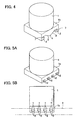
- the hook forming portion 1b is formed in the flat rectangular parallelepiped shape across the whole bottom face of the part 1, and each hook portion 2 (and the chevron portion 4) shown in FIGS. 1A and 1B has a linear cross section.
- FIGS. 5A and 5B show a third example layout of the hook portion 2.
- the flat rectangular parallelepiped hook forming portion 1b is formed across the whole bottom face of the part 1, and a total of four pairs of hook portions 2 opposed to each other are provided, each of which has a linear constant cross section.
- FIGS. 5A and 5B it is shown that the hook portion 2 has no second inclined face 5 (see FIGS. 1A and 1B ), but needless to say, the second inclined face 5 may be formed.
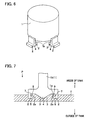
- FIG. 6 shows a fourth example layout of the hook portion 2.
- a plurality of hook forming portions 1b are formed at the outer circumference of the bottom face of the part 1 in the circumferential direction at predetermined intervals.
- Each of the hook forming portions 1b has the pair of hook portions 2 shown in FIGS. 1A and 1B (and the chevron portion 4) having a linear cross section.
- the part 1 can be firmly fixed to the tank wall T because of the mechanical coupling force obtained by the hook portions 2.
Landscapes
- Engineering & Computer Science (AREA)
- Mechanical Engineering (AREA)
- Manufacturing & Machinery (AREA)
- Life Sciences & Earth Sciences (AREA)
- Sustainable Development (AREA)
- Sustainable Energy (AREA)
- Chemical & Material Sciences (AREA)
- Combustion & Propulsion (AREA)
- Transportation (AREA)
- Cooling, Air Intake And Gas Exhaust, And Fuel Tank Arrangements In Propulsion Units (AREA)
- Blow-Moulding Or Thermoforming Of Plastics Or The Like (AREA)
Description
- The present invention relates to a resin-made fuel tank for a vehicle, and more specifically, a part fixing structure and a part fixing method to such a resin-made fuel tank.
- Prior arts of fixing a tank-associated part to a resin-made fuel tank are disclosed in
JP 2009-132297 A JP 2008-507651 A JP 2009-132297 A JP 2008-507651 A - According to
JP 2009-132297 A JP 2008-507651 A - According to
JP 2008-507651 A
Moreover, According toJP 2008-507651 A HDPE layers 2, 2', and an EVOH layer 3) are predetermined, when a resin is poured into the recess of the core in order to form a rivet-like portion (i.e., a plateau portion 8), the layer other than the rivet-like portion should be partially thin by what corresponds to the flowed resin. Hence, in the case of the structure disclosed inFIG 1 ofJP 2008-507651 A document EP 1 099 529 describes a part fixing structure according to the preamble ofclaim 1. - The present invention has been made in view of the foregoing circumstances, and it is an object of the present invention to provide a part fixing structure and a part fixing method to a resin-made fuel tank which can firmly fix a part to a tank wall without the need of providing a convex portion and a recess on a molding die.
- In order to achieve the above object, a first aspect of the present invention provides a part fixing structure according to
claim 1 and a method according toclaim 3.
Further optional details of the invention are described in the dependent claims. - According to the configuration of the first aspect of the present invention, since the part is provided with the hook portion which is buried in the tank wall, the part is thus fixed to the tank wall. Accordingly, it is not necessary to form the resin of the tank wall as a rivet-like engaging portion like
JP 2008-507651 A - According to the configuration of the second aspect of the present invention, fixing of the part to the tank wall becomes stable by the pair of hook portions, and a larger mechanical coupling force can be obtained.
- According to the invention a chevron portion having a pair of first inclined faces is projectingly provided at a bottom face of the part between the pair of hook portions. A further aspect of the invention provides the part fixing structure of the invention, in which a second inclined face which is inclined in a direction opposite to a buried direction of the hook portion toward the tip of the hook portion is formed at a bottom face of each of the pair of hook portions.
- According to the invention, individual first inclined faces of the chevron portion work together as a guide face which positively guides the melted resin of the tank wall into the internal space between the hook portions, so that the resin smoothly flows into the internal space between the hook portion when the hook portion is buried in the tank wall.
- An aspect of the present invention provides a part fixing method according to
claim 3.
According to the invention, the part fixing method comprises a step of causing a resin of the tank wall in the melted state to flow into a space surrounded by the hook portions when the resin-made fuel tank is molded.
An aspect of the present invention provides the part fixing method in which a second inclined face which is inclined in a direction opposite to a buried direction of the hook portion toward the tip of the hook portion is formed at a bottom face of each of the pair of hook portions. -
-
FIG. 1A is a diagram for explaining a hook portion according to the present invention, and is a perspective view showing an outline of the hook portion; -
FIG. 1B is a diagram for explaining the hook portion according to the present invention, and is a side view showing the outline of the hook portion; -
FIG. 2A is a diagram showing how the hook portion of the present invention is buried in a tank wall; -
FIG. 2B is a diagram showing how the hook portion of the present invention is buried in the tank wall; -
FIG. 2C is a diagram showing how the hook portion of the present invention is buried in the tank wall; -
FIG. 2D is a diagram showing how the hook portion of the present invention is buried in the tank wall; -
FIG. 3A is a diagram showing a first example layout of the hook portion, and is a perspective view showing an outline of the hook portion; -
FIG. 3B is a diagram showing the first example layout of the hook portion, and is a bottom view showing the outline of the hook portion; -
FIG. 3C is a diagram showing the first example layout of the hook portion, and is a side cross-sectional view showing the outline of the hook portion; -
FIG. 4 is a perspective view showing a second example layout of the hook portion; -
FIG. 5A is a diagram showing a third example layout of the hook portion, and is a perspective view showing an outline of the hook portion; -
FIG. 5B is a diagram showing the third example layout of the hook portion, and is a side view showing the outline of the hook portion; -
FIG. 6 is a perspective view showing a fourth example layout of the hook portion; and -
FIG. 7 is a side view showing a modified example of the hook portion. -
Reference numeral 1b inFIGS. 1A and 1B indicates a hook forming portion of a part 1 (seeFIGS. 4 and6 ) to be attached to a tank wall T of a resin-made fuel tank. An example of such a resin-made fuel tank is a tank for a vehicle, and examples of such apart 1 are tank-associated sub parts, such as a fuel-pump casing built in the tank and an attachment bracket of such a casing, and a casing for various valves built in the tank and an attachment bracket of such a casing. The shape of such a tank-associated sub part is not limited to any particular shape. The hook forming portion Ibis integrally molded with thepart 1. - The
part 1 is formed of a material like POM (polyacetal resin). In contrast, the tank wall T employs a multi-layer cross-section structure having a barrier layer formed of a material with a superior impermeability against fuel, e.g., EVOH (ethylene-vinyl-alcohol copolymer) sandwiched between, at least an inner thermoplastic resin layer forming a tank inner surface and an outer thermoplastic resin layer forming a tank outer surface. The inner thermoplastic resin layer and the outer thermoplastic resin layer are each formed of, for example, PE (high-density polyethylene) having good thermal melting characteristics and formability. - According to the present invention, the part 1 (the
hook forming portion 1b) is formed withhook portions 2 each having a claw-like cross section, and thehook portions 2 are buried in the tank wall T, thereby fixing thepart 1 to the tank wall T. Thehook portions 2 are integrally molded with thehook forming portion 1b (i.e., the part 1). -
FIGS. 1A and 1B show an embodiment in which a pair ofhook portions 2 is integrally molded so that thehook tips 2a are opposed to each other at a distance. Achevron portion 4 having a pair of first inclined faces 3P is projectingly provided at abottom face 1a (a surface facing the tank wall T) of the part 1 (thehook forming portion 1b) between the pair ofhook portions 2. Also, a secondinclined face 5 that is inclined in a direction opposite to a buried direction P toward thehook tip 2a is formed at a bottom face (a surface facing the tank wall T) of eachhook portion 2. - With reference to
FIGS. 2A to 2D , how to fix thepart 1 will be explained. The resin-made fuel tank is formed by a blow molding die, andFIGS. 2A to 2D show a state in which a parison in a melted state is pasted on adie 6 by blowing as the tank wall T. Thepart 1 is attached to a non-illustrated support rod (e.g., the support rod 41 shown in FIG. 11 ofJP 2009-132297 A die 6. - At the time of blow molding, at least either one of the
die 6 or the support rod is moved in order to move thepart 1 close to the tank wall T from the state shown inFIG. 2A , the melted resin of the tank wall T flows into a hookinginternal space 7 surrounded by the bottom face la of thepart 1 and thehook portions 2 in an order fromFIG .2B to FIG. 2C . In particular, the firstinclined faces 3 of thechevron portion 4 formed at thebottom face 1a of thepart 1, and the second inclined faces 5 formed at respective bottom faces of thehook portions 2 work together in order to function as a guide face which positively guides the melted resin into the hookinginternal space 7, so that the resin smoothly flows into the hookinginternal space 7 when thehook portions 2 are buried in the tank wall T. - Next, when the
hook portions 2 are buried and reach predetermined positions in the tank wall T, as shown inFIG. 2D , the hookinginternal space 7 is completely filled with the melted resin of the tank wall T. Thereafter, when thedie 6 is released and the whole fuel tank taken out from the die is cooled down, the resin of the tank wall T becomes solid, and because of the mechanical coupling force by thehook portions 2, thepart 1 is firmly fixed to the tank wall T. According toJP 2008-507651 A hook portions 2 are pushed in the interior of the parison layer, a resin whose volume corresponds to that to be pushed out merely enters into the hookinginternal space 7, no thin portion is substantially formed, and the layer structure of the parison layer is not substantially deteriorated. - Hereinafter, a plurality of example layouts of the
hook portion 2 to thepart 1 formed in a substantially columned shape (or may be a circular cylindrical shape) will be explained.FIGS. 3A to 3C show a first example layout of thehook portion 2, and a plurality of (in the case ofFIGS. 3A to 3C , four) regions R each having a pair ofhook portions 2 are placed at a circular bottom face of thepart 1 in a circumferential direction at equal intervals. The pair ofhook portions 2 are formed along the circumferential direction of thepart 1 at each region R. The other regions S are planes. As evidenced byFIG. 3C , the hookinginternal space 7 of thehook portions 2 placed outwardly in the radial direction is communicated with anopening 8 on the outer circumference surface of thepart 1. In this example layout, the secondinclined face 5 of thehook portion 2 is formed in a curved surface. -
FIG. 4 shows a second example layout of thehook portion 2. Thehook forming portion 1b is formed in the flat rectangular parallelepiped shape across the whole bottom face of thepart 1, and each hook portion 2 (and the chevron portion 4) shown inFIGS. 1A and 1B has a linear cross section. -
FIGS. 5A and 5B show a third example layout of thehook portion 2. The flat rectangular parallelepipedhook forming portion 1b is formed across the whole bottom face of thepart 1, and a total of four pairs ofhook portions 2 opposed to each other are provided, each of which has a linear constant cross section. InFIGS. 5A and 5B , it is shown that thehook portion 2 has no second inclined face 5 (seeFIGS. 1A and 1B ), but needless to say, the secondinclined face 5 may be formed. -
FIG. 6 shows a fourth example layout of thehook portion 2. A plurality ofhook forming portions 1b are formed at the outer circumference of the bottom face of thepart 1 in the circumferential direction at predetermined intervals. Each of thehook forming portions 1b has the pair ofhook portions 2 shown inFIGS. 1A and 1B (and the chevron portion 4) having a linear cross section. - In the above-explained first to fourth example layouts, the
part 1 can be firmly fixed to the tank wall T because of the mechanical coupling force obtained by thehook portions 2. - In addition, if a third
inclined face 9 which is inclined in the direction opposite to the buried direction P toward thehook tip 2a is further formed at the internal face of thehook portion 2 as shown inFIG. 7 , thehook portion 2 is further engaged into the tank wall T, so that the pulling strength of thepart 1 increases.
Claims (4)
- A part fixing structure that fixes a tank-associated part to a tank wall (T) of a resin-made fuel tank, the part fixing structure comprising:at least a pair of hook portions (2) formed together with the part (1),wherein the at least pair of hook portions (2) is buried in the tank wall (T), thereby fixing the part (1) to the tank wall (T),the at least a pair of hook portions (2) is formed so that respective tips of the hook portions (2) are opposed to each other at a distance, and characterized in thata chevron portion (4) having a pair of first inclined faces (3P) is projectingly provided at a bottom face (1a) of the part (1) between the pair of hook portions (2).
- The part fixing structure according to claim 1, wherein a second inclined face (5) which is inclined in a direction opposite to a buried direction (P) of the hook portion (2) toward the tip of the hook portion (2) is formed at a bottom face (1a) of each of the pair of hook portions (2).
- A part fixing method for fixing a tank-associated part to a tank wall (T) of a resin-made fuel tank, the part (1) being formed together with at least a pair of hook portions (2), the method comprising a step of:burying the pair of hook portions (2) in the tank wall (T) in a melted state when the resin-made fuel tank is molded, thereby fixing the part (1) to the tank wall (T) after the tank wall (T) is cooled,wherein the at least a pair of hook portions (2) is formed so that respective tips of the hook portions (2) are opposed to each other at a distance, and the method further comprising a step of causing a resin of the tank wall (T) in the melted state to flow into a space surrounded by the hook portions (2) when the resin-made fuel tank is molded, anda chevron portion (4) having a pair of first inclined faces (3P) is projectingly provided at a bottom face (1a) of the part (1) between the pair of hook portions (2).
- The part fixing method according to claim 3, wherein a second inclined face (5) which is inclined in a direction opposite to a buried direction (P) of the hook portion (2) toward the tip of the hook portion (2) is formed at a bottom face (1a) of each of the pair of hook portions (2).
Applications Claiming Priority (1)
| Application Number | Priority Date | Filing Date | Title |
|---|---|---|---|
| JP2010009272A JP5097221B2 (en) | 2010-01-19 | 2010-01-19 | Plastic fuel tank component fixing structure |
Publications (2)
| Publication Number | Publication Date |
|---|---|
| EP2353914A1 EP2353914A1 (en) | 2011-08-10 |
| EP2353914B1 true EP2353914B1 (en) | 2012-11-21 |
Family
ID=43642518
Family Applications (1)
| Application Number | Title | Priority Date | Filing Date |
|---|---|---|---|
| EP11151357A Active EP2353914B1 (en) | 2010-01-19 | 2011-01-19 | Part fixing structure to resin-made fuel tank and part fixing method thereto |
Country Status (3)
| Country | Link |
|---|---|
| US (1) | US8668176B2 (en) |
| EP (1) | EP2353914B1 (en) |
| JP (1) | JP5097221B2 (en) |
Cited By (1)
| Publication number | Priority date | Publication date | Assignee | Title |
|---|---|---|---|---|
| DE102016217497A1 (en) | 2016-09-14 | 2018-03-15 | Volkswagen Aktiengesellschaft | Fuel tank for a motor vehicle |
Families Citing this family (17)
| Publication number | Priority date | Publication date | Assignee | Title |
|---|---|---|---|---|
| US9023264B2 (en) * | 2006-07-03 | 2015-05-05 | Kautex Textron Gmbh & Co. Kg | Method for producing a container of thermoplastic material |
| JP5495873B2 (en) * | 2010-03-16 | 2014-05-21 | 株式会社Fts | Automotive fuel tank |
| DE102010032279B4 (en) * | 2010-07-26 | 2012-09-06 | Kautex Textron Gmbh & Co. Kg | Method of riveting an accessory |
| DE102010032931A1 (en) * | 2010-07-30 | 2012-02-02 | Kautex Textron Gmbh & Co. Kg | Container made of thermoplastic material |
| US8973778B2 (en) * | 2012-10-29 | 2015-03-10 | Ti Automotive Technology Center Gmbh | Self-adjusting connector |
| WO2014122747A1 (en) * | 2013-02-07 | 2014-08-14 | 株式会社Fts | Automobile fuel tank |
| JP2014227091A (en) * | 2013-05-23 | 2014-12-08 | 有限会社テル | Interior member |
| JP6020486B2 (en) | 2014-02-21 | 2016-11-02 | トヨタ自動車株式会社 | Resin fuel tank |
| DE102014007121A1 (en) * | 2014-05-16 | 2015-11-19 | Kautex Textron Gmbh & Co. Kg | Container of thermoplastic polymer and method for producing such a container |
| EP2946905B1 (en) * | 2014-05-23 | 2017-03-22 | Inergy Automotive Systems Research (Société Anonyme) | Process for fastening an accessory in a blow molded plastic tank |
| JP6395253B2 (en) * | 2014-08-07 | 2018-09-26 | 株式会社Fts | Mounting structure for internal parts of automobile fuel tank |
| JP6350440B2 (en) * | 2015-08-06 | 2018-07-04 | トヨタ自動車株式会社 | Built-in component fixing structure of resin tank |
| JP6334070B2 (en) * | 2015-10-23 | 2018-06-06 | 八千代工業株式会社 | Welding method and welded structure |
| DE102016219539A1 (en) * | 2016-10-07 | 2018-04-12 | Kautex Textron Gmbh & Co. Kg | Stiffening element for a fluid container for a motor vehicle and fluid container for a motor vehicle with a stiffening element |
| JP7051015B2 (en) * | 2019-07-18 | 2022-04-08 | 八千代工業株式会社 | Fuel tank |
| CN110884009B (en) * | 2019-10-22 | 2021-05-25 | 厦门迈勒滚塑有限公司 | Forming process of external interface of plastic oil tank |
| EP3907058B1 (en) * | 2020-05-07 | 2024-03-13 | MAGNA Energy Storage Systems GesmbH | Plastic container with inserted element and method of manufacture thereof |
Family Cites Families (29)
| Publication number | Priority date | Publication date | Assignee | Title |
|---|---|---|---|---|
| US2705346A (en) * | 1952-11-14 | 1955-04-05 | Raymond M Schlabach | Method of working plastic |
| US4323411A (en) * | 1976-09-27 | 1982-04-06 | Owens-Illinois, Inc. | Method for applying prefabricated parts to blow molded articles |
| US4125339A (en) * | 1977-06-29 | 1978-11-14 | Pittinger Sr Charles B | Releasably interlocked, assymmetrical, lugged flange joint with fixed relative orientation |
| DE2924198C2 (en) * | 1979-06-15 | 1987-01-02 | Kautex Werke Reinold Hagen AG, 5300 Bonn | Hollow body made of thermoplastic material produced by blow molding |
| US4891000A (en) * | 1987-02-06 | 1990-01-02 | Nissan Motor Co., Ltd. | Apparatus for blow moulding hollow article |
| DE4203705A1 (en) * | 1992-02-08 | 1993-08-12 | Kautex Werke Gmbh | METHOD FOR PRODUCING HOLLOW BODIES FROM THERMOPLASTIC PLASTIC AND HOLLOW BODIES FROM THERMOPLASTIC PLASTIC |
| US5219135A (en) * | 1992-03-04 | 1993-06-15 | Delco Electronics Corporation | Apparatus for mounting air core gauges |
| US5308427A (en) * | 1992-09-28 | 1994-05-03 | Ford Motor Company | Method for fastening plastic articles |
| US5445783A (en) * | 1993-07-06 | 1995-08-29 | Ford Motor Company | Blow molding method |
| US5909008A (en) * | 1996-01-29 | 1999-06-01 | Pelaez; Pedro R. | Mounting mechanism for instruments having flanges |
| US5947311A (en) * | 1997-05-06 | 1999-09-07 | Owens-Illinois Closure Inc. | Plastic closure with liner having a periphery spaced from the skirt of the closure and a sealing surface angled axially with respect to the base wall of the closure |
| DE19833157A1 (en) * | 1998-07-23 | 2000-01-27 | Bosch Gmbh Robert | Holding fixture for vehicle gyro navigation instrument suitable for installation in a wide range of vehicles irrespective of orientation |
| FR2801003B1 (en) * | 1999-11-12 | 2002-09-06 | Plastic Omnium Cie | PROCESS FOR PRODUCING A BLOWN ENCLOSURE PROVIDED WITH A MOUTHPIECE CAPABLE OF RECEIVING A CONDUIT, AN INSERT FOR MOLDING BY BLOWING A PARISON AND A BLOWN ENCLOSURE COMPRISING SUCH A OVERMOLDED INSERT |
| JP3824212B2 (en) * | 2000-11-17 | 2006-09-20 | 豊田合成株式会社 | Valve with fuel tank |
| FR2806959B1 (en) * | 2000-04-03 | 2003-02-14 | Plastic Omnium Cie | METHOD FOR MANUFACTURING A BLOWER THERMOPLASTIC TANK INCORPORATING AN INSERT |
| FR2807976B1 (en) * | 2000-04-20 | 2002-06-28 | Plastic Omnium Cie | MOTOR VEHICLE FUEL TANK |
| FR2811404B1 (en) * | 2000-07-06 | 2002-08-16 | Commissariat Energie Atomique | LOCKABLE AND UNLOCKABLE ASSEMBLY SYSTEM OF TWO TUBULAR PARTS |
| US6978802B2 (en) | 2001-03-08 | 2005-12-27 | Toyoda Gosei Co., Ltd. | Fuel tank and manufacturing method thereof |
| FR2827818B1 (en) * | 2001-07-25 | 2003-10-24 | Inergy Automotive Systems Man | BLINDING SYSTEM FOR FUEL TANK FILLING TUBE AND METHOD FOR OPENING SAME |
| FR2833890B1 (en) * | 2001-12-21 | 2005-04-22 | Inergy Automotive Systems Man | FUEL TANK FOR MOTOR VEHICLE |
| US7059305B2 (en) * | 2003-07-21 | 2006-06-13 | Automotive Components Holdings, Llc | Internalized component for fuel tanks |
| FR2873321B1 (en) | 2004-07-23 | 2008-05-09 | Inergy Automotive Systems Res | METHOD FOR FIXING AN ACCESSORY IN A FUEL TANK OF PLASTIC MATERIAL |
| US7497917B2 (en) * | 2005-08-31 | 2009-03-03 | Gm Global Technology Operations, Inc. | Friction heating for joining dissimilar materials |
| DE102006006469B4 (en) | 2006-02-10 | 2018-02-22 | Kautex Textron Gmbh & Co. Kg | Method for producing a plastic container |
| FR2918595B1 (en) * | 2007-07-11 | 2009-10-09 | Inergy Automotive Systems Res | METHOD FOR FIXING AN ACCESSORY IN A PLASTIC RESERVOIR |
| JP5270911B2 (en) | 2007-11-30 | 2013-08-21 | 株式会社Fts | Automotive fuel tank |
| FR2934804A1 (en) * | 2008-08-07 | 2010-02-12 | Inergy Automotive Systems Res | PROCESS FOR THE MANUFACTURE OF A FUEL TANK OF PLASTIC MATERIAL. |
| JP4832480B2 (en) * | 2008-08-08 | 2011-12-07 | 八千代工業株式会社 | Fuel tank protective plate mounting structure |
| US8459013B2 (en) * | 2008-12-30 | 2013-06-11 | Daimler Trucks North America Llc | Urea tank with closure member for vehicle exhaust system |
-
2010
- 2010-01-19 JP JP2010009272A patent/JP5097221B2/en active Active
-
2011
- 2011-01-19 US US13/009,257 patent/US8668176B2/en active Active
- 2011-01-19 EP EP11151357A patent/EP2353914B1/en active Active
Cited By (2)
| Publication number | Priority date | Publication date | Assignee | Title |
|---|---|---|---|---|
| DE102016217497A1 (en) | 2016-09-14 | 2018-03-15 | Volkswagen Aktiengesellschaft | Fuel tank for a motor vehicle |
| DE102016217497B4 (en) | 2016-09-14 | 2024-06-27 | Volkswagen Aktiengesellschaft | Fuel tank for a motor vehicle and method for producing a fuel tank |
Also Published As
| Publication number | Publication date |
|---|---|
| US20110174946A1 (en) | 2011-07-21 |
| JP2011148337A (en) | 2011-08-04 |
| EP2353914A1 (en) | 2011-08-10 |
| JP5097221B2 (en) | 2012-12-12 |
| US8668176B2 (en) | 2014-03-11 |
Similar Documents
| Publication | Publication Date | Title |
|---|---|---|
| US8668176B2 (en) | Part fixing structure to resin-made fuel tank and part fixing method thereto | |
| US10940754B2 (en) | Tank comprising a reinforcement member and method for manufacturing such a reinforcement member | |
| JP5810088B2 (en) | Fuel tank support | |
| US6843384B2 (en) | Fuel tank | |
| US20150217635A1 (en) | Automobile fuel tank | |
| US20190309903A1 (en) | High pressure tank | |
| US6475625B2 (en) | Plastic parts joining structure | |
| JP2016037253A (en) | Suspension arm for vehicle | |
| KR102302975B1 (en) | Liquid container for automobile and injection molding method thereof | |
| JP2015058715A (en) | Fuel tank for vehicle | |
| CN112955381B (en) | container | |
| JP2015089771A (en) | Fuel tank for automobile | |
| EP0930189B1 (en) | Hollow resin container | |
| JPWO2017169351A1 (en) | Method for producing foam composite molded body, in-mold foam molded body unit, foam composite molded body, and mold for foam composite molding | |
| KR20080102206A (en) | Fuel Tank Connector | |
| JP2009113704A (en) | Fuel tank made of thermoplastic synthetic resin | |
| JP2016203579A (en) | Resin optical molded article and production method thereof | |
| EP3052335B1 (en) | Tank with internal connecting member and method for assembling such a tank | |
| JP6184743B2 (en) | Plastic hollow container | |
| JP6274795B2 (en) | Automotive fuel tank | |
| CN119458987A (en) | Molded boxes formed from multiple materials | |
| JP2006321309A (en) | Fuel tank for automobile and manufacturing method thereof | |
| JP2016020061A (en) | Blow molding | |
| US12441179B2 (en) | Fuel tank | |
| JP2005199885A (en) | Synthetic resin hollow body, automobile fuel tank and method for producing the same |
Legal Events
| Date | Code | Title | Description |
|---|---|---|---|
| PUAI | Public reference made under article 153(3) epc to a published international application that has entered the european phase |
Free format text: ORIGINAL CODE: 0009012 |
|
| AK | Designated contracting states |
Kind code of ref document: A1 Designated state(s): AL AT BE BG CH CY CZ DE DK EE ES FI FR GB GR HR HU IE IS IT LI LT LU LV MC MK MT NL NO PL PT RO RS SE SI SK SM TR |
|
| AX | Request for extension of the european patent |
Extension state: BA ME |
|
| 17P | Request for examination filed |
Effective date: 20120206 |
|
| RIC1 | Information provided on ipc code assigned before grant |
Ipc: B29C 41/20 20060101ALI20120625BHEP Ipc: B29C 65/02 20060101ALI20120625BHEP Ipc: B60K 15/03 20060101AFI20120625BHEP |
|
| GRAP | Despatch of communication of intention to grant a patent |
Free format text: ORIGINAL CODE: EPIDOSNIGR1 |
|
| GRAS | Grant fee paid |
Free format text: ORIGINAL CODE: EPIDOSNIGR3 |
|
| GRAA | (expected) grant |
Free format text: ORIGINAL CODE: 0009210 |
|
| AK | Designated contracting states |
Kind code of ref document: B1 Designated state(s): AL AT BE BG CH CY CZ DE DK EE ES FI FR GB GR HR HU IE IS IT LI LT LU LV MC MK MT NL NO PL PT RO RS SE SI SK SM TR |
|
| REG | Reference to a national code |
Ref country code: GB Ref legal event code: FG4D |
|
| REG | Reference to a national code |
Ref country code: CH Ref legal event code: EP |
|
| REG | Reference to a national code |
Ref country code: AT Ref legal event code: REF Ref document number: 584880 Country of ref document: AT Kind code of ref document: T Effective date: 20121215 |
|
| REG | Reference to a national code |
Ref country code: IE Ref legal event code: FG4D |
|
| REG | Reference to a national code |
Ref country code: DE Ref legal event code: R096 Ref document number: 602011000458 Country of ref document: DE Effective date: 20130117 |
|
| REG | Reference to a national code |
Ref country code: NL Ref legal event code: VDEP Effective date: 20121121 |
|
| REG | Reference to a national code |
Ref country code: AT Ref legal event code: MK05 Ref document number: 584880 Country of ref document: AT Kind code of ref document: T Effective date: 20121121 |
|
| REG | Reference to a national code |
Ref country code: LT Ref legal event code: MG4D |
|
| PG25 | Lapsed in a contracting state [announced via postgrant information from national office to epo] |
Ref country code: NO Free format text: LAPSE BECAUSE OF FAILURE TO SUBMIT A TRANSLATION OF THE DESCRIPTION OR TO PAY THE FEE WITHIN THE PRESCRIBED TIME-LIMIT Effective date: 20130221 Ref country code: ES Free format text: LAPSE BECAUSE OF FAILURE TO SUBMIT A TRANSLATION OF THE DESCRIPTION OR TO PAY THE FEE WITHIN THE PRESCRIBED TIME-LIMIT Effective date: 20130304 Ref country code: HR Free format text: LAPSE BECAUSE OF FAILURE TO SUBMIT A TRANSLATION OF THE DESCRIPTION OR TO PAY THE FEE WITHIN THE PRESCRIBED TIME-LIMIT Effective date: 20121121 Ref country code: SE Free format text: LAPSE BECAUSE OF FAILURE TO SUBMIT A TRANSLATION OF THE DESCRIPTION OR TO PAY THE FEE WITHIN THE PRESCRIBED TIME-LIMIT Effective date: 20121121 Ref country code: LT Free format text: LAPSE BECAUSE OF FAILURE TO SUBMIT A TRANSLATION OF THE DESCRIPTION OR TO PAY THE FEE WITHIN THE PRESCRIBED TIME-LIMIT Effective date: 20121121 Ref country code: FI Free format text: LAPSE BECAUSE OF FAILURE TO SUBMIT A TRANSLATION OF THE DESCRIPTION OR TO PAY THE FEE WITHIN THE PRESCRIBED TIME-LIMIT Effective date: 20121121 |
|
| PG25 | Lapsed in a contracting state [announced via postgrant information from national office to epo] |
Ref country code: PT Free format text: LAPSE BECAUSE OF FAILURE TO SUBMIT A TRANSLATION OF THE DESCRIPTION OR TO PAY THE FEE WITHIN THE PRESCRIBED TIME-LIMIT Effective date: 20130321 Ref country code: GR Free format text: LAPSE BECAUSE OF FAILURE TO SUBMIT A TRANSLATION OF THE DESCRIPTION OR TO PAY THE FEE WITHIN THE PRESCRIBED TIME-LIMIT Effective date: 20130222 Ref country code: LV Free format text: LAPSE BECAUSE OF FAILURE TO SUBMIT A TRANSLATION OF THE DESCRIPTION OR TO PAY THE FEE WITHIN THE PRESCRIBED TIME-LIMIT Effective date: 20121121 Ref country code: BE Free format text: LAPSE BECAUSE OF FAILURE TO SUBMIT A TRANSLATION OF THE DESCRIPTION OR TO PAY THE FEE WITHIN THE PRESCRIBED TIME-LIMIT Effective date: 20121121 Ref country code: SI Free format text: LAPSE BECAUSE OF FAILURE TO SUBMIT A TRANSLATION OF THE DESCRIPTION OR TO PAY THE FEE WITHIN THE PRESCRIBED TIME-LIMIT Effective date: 20121121 Ref country code: PL Free format text: LAPSE BECAUSE OF FAILURE TO SUBMIT A TRANSLATION OF THE DESCRIPTION OR TO PAY THE FEE WITHIN THE PRESCRIBED TIME-LIMIT Effective date: 20121121 |
|
| PG25 | Lapsed in a contracting state [announced via postgrant information from national office to epo] |
Ref country code: AT Free format text: LAPSE BECAUSE OF FAILURE TO SUBMIT A TRANSLATION OF THE DESCRIPTION OR TO PAY THE FEE WITHIN THE PRESCRIBED TIME-LIMIT Effective date: 20121121 |
|
| PG25 | Lapsed in a contracting state [announced via postgrant information from national office to epo] |
Ref country code: BG Free format text: LAPSE BECAUSE OF FAILURE TO SUBMIT A TRANSLATION OF THE DESCRIPTION OR TO PAY THE FEE WITHIN THE PRESCRIBED TIME-LIMIT Effective date: 20130221 Ref country code: EE Free format text: LAPSE BECAUSE OF FAILURE TO SUBMIT A TRANSLATION OF THE DESCRIPTION OR TO PAY THE FEE WITHIN THE PRESCRIBED TIME-LIMIT Effective date: 20121121 Ref country code: RS Free format text: LAPSE BECAUSE OF FAILURE TO SUBMIT A TRANSLATION OF THE DESCRIPTION OR TO PAY THE FEE WITHIN THE PRESCRIBED TIME-LIMIT Effective date: 20121121 Ref country code: DK Free format text: LAPSE BECAUSE OF FAILURE TO SUBMIT A TRANSLATION OF THE DESCRIPTION OR TO PAY THE FEE WITHIN THE PRESCRIBED TIME-LIMIT Effective date: 20121121 Ref country code: SK Free format text: LAPSE BECAUSE OF FAILURE TO SUBMIT A TRANSLATION OF THE DESCRIPTION OR TO PAY THE FEE WITHIN THE PRESCRIBED TIME-LIMIT Effective date: 20121121 Ref country code: CZ Free format text: LAPSE BECAUSE OF FAILURE TO SUBMIT A TRANSLATION OF THE DESCRIPTION OR TO PAY THE FEE WITHIN THE PRESCRIBED TIME-LIMIT Effective date: 20121121 |
|
| PG25 | Lapsed in a contracting state [announced via postgrant information from national office to epo] |
Ref country code: RO Free format text: LAPSE BECAUSE OF FAILURE TO SUBMIT A TRANSLATION OF THE DESCRIPTION OR TO PAY THE FEE WITHIN THE PRESCRIBED TIME-LIMIT Effective date: 20121121 Ref country code: MC Free format text: LAPSE BECAUSE OF NON-PAYMENT OF DUE FEES Effective date: 20130131 Ref country code: NL Free format text: LAPSE BECAUSE OF FAILURE TO SUBMIT A TRANSLATION OF THE DESCRIPTION OR TO PAY THE FEE WITHIN THE PRESCRIBED TIME-LIMIT Effective date: 20121121 Ref country code: IT Free format text: LAPSE BECAUSE OF FAILURE TO SUBMIT A TRANSLATION OF THE DESCRIPTION OR TO PAY THE FEE WITHIN THE PRESCRIBED TIME-LIMIT Effective date: 20121121 |
|
| PLBE | No opposition filed within time limit |
Free format text: ORIGINAL CODE: 0009261 |
|
| STAA | Information on the status of an ep patent application or granted ep patent |
Free format text: STATUS: NO OPPOSITION FILED WITHIN TIME LIMIT |
|
| REG | Reference to a national code |
Ref country code: IE Ref legal event code: MM4A |
|
| 26N | No opposition filed |
Effective date: 20130822 |
|
| REG | Reference to a national code |
Ref country code: DE Ref legal event code: R097 Ref document number: 602011000458 Country of ref document: DE Effective date: 20130822 |
|
| PG25 | Lapsed in a contracting state [announced via postgrant information from national office to epo] |
Ref country code: AL Free format text: LAPSE BECAUSE OF FAILURE TO SUBMIT A TRANSLATION OF THE DESCRIPTION OR TO PAY THE FEE WITHIN THE PRESCRIBED TIME-LIMIT Effective date: 20121121 Ref country code: IE Free format text: LAPSE BECAUSE OF NON-PAYMENT OF DUE FEES Effective date: 20130119 |
|
| PG25 | Lapsed in a contracting state [announced via postgrant information from national office to epo] |
Ref country code: MT Free format text: LAPSE BECAUSE OF FAILURE TO SUBMIT A TRANSLATION OF THE DESCRIPTION OR TO PAY THE FEE WITHIN THE PRESCRIBED TIME-LIMIT Effective date: 20121121 |
|
| REG | Reference to a national code |
Ref country code: CH Ref legal event code: PL |
|
| PG25 | Lapsed in a contracting state [announced via postgrant information from national office to epo] |
Ref country code: CH Free format text: LAPSE BECAUSE OF NON-PAYMENT OF DUE FEES Effective date: 20140131 Ref country code: LI Free format text: LAPSE BECAUSE OF NON-PAYMENT OF DUE FEES Effective date: 20140131 |
|
| PG25 | Lapsed in a contracting state [announced via postgrant information from national office to epo] |
Ref country code: SM Free format text: LAPSE BECAUSE OF FAILURE TO SUBMIT A TRANSLATION OF THE DESCRIPTION OR TO PAY THE FEE WITHIN THE PRESCRIBED TIME-LIMIT Effective date: 20121121 |
|
| PG25 | Lapsed in a contracting state [announced via postgrant information from national office to epo] |
Ref country code: TR Free format text: LAPSE BECAUSE OF FAILURE TO SUBMIT A TRANSLATION OF THE DESCRIPTION OR TO PAY THE FEE WITHIN THE PRESCRIBED TIME-LIMIT Effective date: 20121121 Ref country code: CY Free format text: LAPSE BECAUSE OF FAILURE TO SUBMIT A TRANSLATION OF THE DESCRIPTION OR TO PAY THE FEE WITHIN THE PRESCRIBED TIME-LIMIT Effective date: 20121121 |
|
| PG25 | Lapsed in a contracting state [announced via postgrant information from national office to epo] |
Ref country code: HU Free format text: LAPSE BECAUSE OF FAILURE TO SUBMIT A TRANSLATION OF THE DESCRIPTION OR TO PAY THE FEE WITHIN THE PRESCRIBED TIME-LIMIT; INVALID AB INITIO Effective date: 20110119 Ref country code: MK Free format text: LAPSE BECAUSE OF FAILURE TO SUBMIT A TRANSLATION OF THE DESCRIPTION OR TO PAY THE FEE WITHIN THE PRESCRIBED TIME-LIMIT Effective date: 20121121 Ref country code: LU Free format text: LAPSE BECAUSE OF NON-PAYMENT OF DUE FEES Effective date: 20130119 |
|
| REG | Reference to a national code |
Ref country code: FR Ref legal event code: PLFP Year of fee payment: 6 |
|
| PG25 | Lapsed in a contracting state [announced via postgrant information from national office to epo] |
Ref country code: IS Free format text: LAPSE BECAUSE OF FAILURE TO SUBMIT A TRANSLATION OF THE DESCRIPTION OR TO PAY THE FEE WITHIN THE PRESCRIBED TIME-LIMIT Effective date: 20121121 |
|
| REG | Reference to a national code |
Ref country code: FR Ref legal event code: PLFP Year of fee payment: 7 |
|
| REG | Reference to a national code |
Ref country code: FR Ref legal event code: PLFP Year of fee payment: 8 |
|
| REG | Reference to a national code |
Ref country code: DE Ref legal event code: R084 Ref document number: 602011000458 Country of ref document: DE |
|
| PGFP | Annual fee paid to national office [announced via postgrant information from national office to epo] |
Ref country code: GB Payment date: 20241128 Year of fee payment: 15 |
|
| PGFP | Annual fee paid to national office [announced via postgrant information from national office to epo] |
Ref country code: FR Payment date: 20241209 Year of fee payment: 15 |
|
| PGFP | Annual fee paid to national office [announced via postgrant information from national office to epo] |
Ref country code: DE Payment date: 20241203 Year of fee payment: 15 |