EP2353782A1 - Peening process for enhancing surface finish of a component - Google Patents
Peening process for enhancing surface finish of a component Download PDFInfo
- Publication number
- EP2353782A1 EP2353782A1 EP11153601A EP11153601A EP2353782A1 EP 2353782 A1 EP2353782 A1 EP 2353782A1 EP 11153601 A EP11153601 A EP 11153601A EP 11153601 A EP11153601 A EP 11153601A EP 2353782 A1 EP2353782 A1 EP 2353782A1
- Authority
- EP
- European Patent Office
- Prior art keywords
- peening
- glass bead
- intensity
- component
- peening operation
- Prior art date
- Legal status (The legal status is an assumption and is not a legal conclusion. Google has not performed a legal analysis and makes no representation as to the accuracy of the status listed.)
- Granted
Links
Images


Classifications
-
- B—PERFORMING OPERATIONS; TRANSPORTING
- B24—GRINDING; POLISHING
- B24C—ABRASIVE OR RELATED BLASTING WITH PARTICULATE MATERIAL
- B24C1/00—Methods for use of abrasive blasting for producing particular effects; Use of auxiliary equipment in connection with such methods
- B24C1/10—Methods for use of abrasive blasting for producing particular effects; Use of auxiliary equipment in connection with such methods for compacting surfaces, e.g. shot-peening
-
- B—PERFORMING OPERATIONS; TRANSPORTING
- B24—GRINDING; POLISHING
- B24C—ABRASIVE OR RELATED BLASTING WITH PARTICULATE MATERIAL
- B24C7/00—Equipment for feeding abrasive material; Controlling the flowability, constitution, or other physical characteristics of abrasive blasts
- B24C7/0007—Equipment for feeding abrasive material; Controlling the flowability, constitution, or other physical characteristics of abrasive blasts the abrasive material being fed in a liquid carrier
-
- C—CHEMISTRY; METALLURGY
- C21—METALLURGY OF IRON
- C21D—MODIFYING THE PHYSICAL STRUCTURE OF FERROUS METALS; GENERAL DEVICES FOR HEAT TREATMENT OF FERROUS OR NON-FERROUS METALS OR ALLOYS; MAKING METAL MALLEABLE, e.g. BY DECARBURISATION OR TEMPERING
- C21D7/00—Modifying the physical properties of iron or steel by deformation
- C21D7/02—Modifying the physical properties of iron or steel by deformation by cold working
- C21D7/04—Modifying the physical properties of iron or steel by deformation by cold working of the surface
- C21D7/06—Modifying the physical properties of iron or steel by deformation by cold working of the surface by shot-peening or the like
-
- Y—GENERAL TAGGING OF NEW TECHNOLOGICAL DEVELOPMENTS; GENERAL TAGGING OF CROSS-SECTIONAL TECHNOLOGIES SPANNING OVER SEVERAL SECTIONS OF THE IPC; TECHNICAL SUBJECTS COVERED BY FORMER USPC CROSS-REFERENCE ART COLLECTIONS [XRACs] AND DIGESTS
- Y10—TECHNICAL SUBJECTS COVERED BY FORMER USPC
- Y10T—TECHNICAL SUBJECTS COVERED BY FORMER US CLASSIFICATION
- Y10T29/00—Metal working
- Y10T29/47—Burnishing
- Y10T29/479—Burnishing by shot peening or blasting
Definitions
- This invention relates to processes for modifying the surface of an article. More particularly, this invention is directed to peening processes by which mechanical properties and surface finish characteristics of a component can be improved.
- Shot peening is a process by which the surface and immediate underlying substrate regions of a component can be modified to exhibit improved properties, including improved resistance to fatigue and foreign object damage by inducing compressive residual stresses.
- Certain components of turbomachinery including airfoil components such as gas turbine blades, steam turbine blades, and gas turbine engine blades formed of steel, titanium-based alloys and superalloys, may require complete shot peening of their airfoil surfaces at relatively high intensities, for example, an Almen intensity of 10N on the Almen N strip scale (about 3A on the Almen A strip scale) or higher, to obtain the desired surface properties (all peening intensities referred to herein are quantified on either the Almen A or N strip scale).
- compressor blades In order to reduce roughness following peening, compressor blades often undergo a polishing process, such as prolonged tumbling, hydro-honing, drag finishing, chemical etching, or other methods to reduce the surface finish to more acceptable levels, for example, 35 microinches (about 0.9 micrometers) Ra.
- a polishing process such as prolonged tumbling, hydro-honing, drag finishing, chemical etching, or other methods to reduce the surface finish to more acceptable levels, for example, 35 microinches (about 0.9 micrometers) Ra.
- the resulting surface finish is often higher than the original pre-peened airfoil surface finish.
- post shot-peen polishing processes can also negate the benefits obtained from shot peening by removing the compressive residual stress layers, and in so doing can also cause dimensional distortion.
- the present invention provides a process for treating a surface of a component to improve its surface finish and induce residual compressive stresses in a near-surface region of the component.
- the process entails performing a first peening operation to form residual compressive stress layers in the near-surface region of a component, and then performing at least a second peening operation to cause surface smoothing of the surface of the component while retaining residual compressive stresses in the near-surface region of the component.
- the first peening operation comprises wet glass bead peening at a first intensity with a first glass bead media
- the second peening operation comprises wet glass bead peening at a second intensity with a second glass bead media, wherein the second intensity is lower than the first intensity and the second glass bead media is smaller than the first glass bead media.
- the process achieves a smooth surface finish in the as-peened condition without the need for post-peen polishing processes that tend to remove the desirable residual compressive stress layers induced by the first peening operation and may cause dimensional distortion of the component.
- the invention is also capable of significantly reducing production time and costs of a component.
- the present invention is generally applicable to components that benefit from the effects of shot peening, including improved fatigue properties, but also require relatively smooth surface finishes of less than 35 microinches (about 0.9 micrometers) Ra, such as 25 microinches (about 0.6 micrometers) Ra or less, that are not achievable with conventional shot peening processes.
- Notable examples of such components include airfoil components of turbomachinery, including gas turbine blades, steam turbine blades, and gas turbine engine blades formed of steel, titanium-based alloys and superalloys, whose airfoils are subjected to high fatigue loads. While the advantages of this invention will be described with reference to compressor blades, the teachings of this invention are generally applicable to any component that benefits from smooth surface finishes and fatigue resistance.
- the invention generally entails a peening process by which peening mediae of at least two different sizes are employed in sequence and in a manner that initially induces a desirable level of compressive residual stress layers in the near-surface region of a component, followed by surface smoothing without removing the desired compressive residual stresses. More particularly, the peening process is a wet glass bead peening process that involves wet glass bead peening performed at a first Almen intensity with a relatively coarse glass bead media, followed by another wet glass bead peening operation performed at a lower Almen intensity with a finer glass bead media.
- the first Almen intensity is preferably at least 7N, for example, 7N to 14N, and more preferably 9N to 12N, and the lower Almen intensity is preferably less than 6N, more preferably about one fourth to about one third of the first Almen intensity, for example, 2N to 5N.
- the glass bead mediae used to achieve the first and second intensities should have diameters as large as practical for the selected intensity range.
- the relatively coarse glass bead media for achieving the first intensity should have diameters of greater than 0.50 millimeter, as a nonlimiting example, about 0.70 millimeter (e.g., GP234 or equivalent), and the relatively finer glass bead media for achieving the lower intensity has smaller diameters, such as about one fourth to about one third of the relatively coarse glass bead media, as a nonlimiting example, about 0.2 millimeter (e.g., GP20 or equivalent).
- the first peening operation is intended to induce the desired compressive residual stress layers in the near-surface region of the blade, while the second peening operation is intended to cause surface smoothing by removing asperities created by the first peening operation.
- the second peening operation substantially retains the full benefits of the preceding peening operation and avoids the risk of part distortion associated with polishing processes.
- a first blade underwent shot peening with CCW-14 stainless steel wire shot (diameter of about 0.014 inch (about 0.35 mm) at an Almen intensity of about 10N to 12N, followed by a lengthy tumbling vibratory polish operation.
- a second blade underwent the same peening operation as the first, but without the additional tumbling operation.
- a third blade underwent wet glass bead peening with GP234 glass beads (diameter of about 0.028 inch (about 0.70 mm)) at an Almen intensity of about 9N to 12N, followed by wet glass bead peening with GP20 glass beads (diameter of about 0.008 inch (about 0.20 mm)) at an Almen intensity of about 3N.
- GP234 glass beads diameter of about 0.028 inch (about 0.70 mm)
- Almen intensity of about 3N Almen intensity of about 3N.
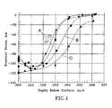
- FIG. 1 is a graph plotting the case depth of residual compressive stresses induced by the three surface treatments, and evidences that higher residual compressive stresses were achieved at significantly greater case depths in the blade that underwent the two-step peening process.
- CC and "CV” identify data obtained from the concave and convex surfaces, respectively, of Specimen A.
- Specimen C which underwent the two-step peening surface treatment exhibited the highest residual compressive stresses throughout its entire near-surface region, which corresponded to a depth of about 0.006 inch (about 150 micrometers) below the surface of the blade.
- a second of these blades underwent peening with S110 cast steel shot (diameter of about 0.014 inch (about 0.35 mm) or less) to achieve full surface coverage and an Almen intensity of about 10N
- the third blade underwent peening with S 170 cast steel shot (diameter of about 0.02 inch (about 0.50 mm)) to achieve full surface coverage and an Almen intensity of about 10N.
- the second peening step performed on Specimens D, E and F employed the same GP20 glass bead slurry, coverage, intensity (about 3N), and duration as used in the previous investigation.
- FIG. 2 is a normal probability plot of surface roughness data on a percentile basis for Specimens D, E and F of the second investigation, as well as Specimens B and C from the first investigation. From this graph, it is evident that the surface finish attainable with the GP20 glass bead slurry was dependent on the media used in the first peening operation, and that far better surface finishes were attained when the first peening operation employed the larger GP234 glass beads (diameter of about 0.70 mm), as opposed to the finer GP165 glass beads (diameter of about 0.50 mm) and either of the cast shot mediae (diameters of about 0.35 and 0.50 mm).
- the mean surface finish of the unpolished Specimen B (peened with CCW-14 stainless steel wire shot (about 0.35 mm diameter; Almen intensity of about 10N to 12N; no tumbling or second peening operation) was about 100 microinches (about 2.5 micrometers) Ra, whereas the mean surface finishes for Specimen E peened with S110 cast shot (0.35 mm diameter), Specimen F peened with S 170 cast steel shot (0.50 mm diameter), and Specimen D peened with GP165 glass beads (0.50 mm diameter) were within a range of about 46 to 53 microinches (about 1.2 to about 1.3 micrometers) Ra.
- FIGS. 3 and 4 are scanned images of microphotographs showing the appearance of the airfoil surfaces of Specimens C and B, respectively, and evidence the drastic improvement in surface finish achieved with the second peening operation performed on Specimen C.
- a two-step peening process can achieve desirable levels of residual compressive stresses and surface roughnesses of about 25 microinches (about 0.64 micrometers) and less by employing a first slurry containing a glass bead media of greater than 0.50 millimeter particles, followed by a second peening operation at a lower intensity using a second slurry containing a finer glass bead media. More generally, it was concluded that the glass bead mediae used to achieve the intensities of the first and second peening operations should have diameters as large as practical for their respective intensities.
- the first wet glass bead peening operation should preferably be performed using a relatively coarser glass bead media having diameters of greater than 0.50 mm to about 0.90 mm, more preferably about 0.60 to about 0.80 mm, and achieve an Almen intensity of at least 7N and to about 14N, more preferably about 9N to about 13N
- the second glass bead peening operation should preferably be performed at an Almen intensity of less than 6N, more preferably about one fourth to about one third of the first Almen intensity, for example, 2N to 5N, using a smaller glass bead media than the first, preferably about one fourth to about one third of the relatively coarse glass bead media, for example, about 0.15 to about 0.25 mm.
- the surface finish following the second peening operation is about one fourth to about one half the surface finish following the first operation, for example, if the surface roughness after the first peening operation is about 70 to about 100 microinches (about 1.8 to about 2.5 micrometer), the second peening operation is carried out to achieve a surface finish of about 20 to about 50 microinches (about 0.5 to about 1.3 micrometer).
Landscapes
- Engineering & Computer Science (AREA)
- Mechanical Engineering (AREA)
- Chemical & Material Sciences (AREA)
- Crystallography & Structural Chemistry (AREA)
- Materials Engineering (AREA)
- Metallurgy (AREA)
- Organic Chemistry (AREA)
- Structures Of Non-Positive Displacement Pumps (AREA)
- Turbine Rotor Nozzle Sealing (AREA)
Abstract
Description
- This invention relates to processes for modifying the surface of an article. More particularly, this invention is directed to peening processes by which mechanical properties and surface finish characteristics of a component can be improved.
- Shot peening is a process by which the surface and immediate underlying substrate regions of a component can be modified to exhibit improved properties, including improved resistance to fatigue and foreign object damage by inducing compressive residual stresses. Certain components of turbomachinery, including airfoil components such as gas turbine blades, steam turbine blades, and gas turbine engine blades formed of steel, titanium-based alloys and superalloys, may require complete shot peening of their airfoil surfaces at relatively high intensities, for example, an Almen intensity of 10N on the Almen N strip scale (about 3A on the Almen A strip scale) or higher, to obtain the desired surface properties (all peening intensities referred to herein are quantified on either the Almen A or N strip scale). However, shot peening at high intensities tends to cause significant surface roughening of an airfoil surface, for example, about 90 microinches (about 2.3 micrometers) Ra and greater, which can be detrimental to blade aerodynamics and the overall performance of the turbine. Increased surface roughness also promotes the adhesion of airborne contaminants, corrodents, and erodents whose deposits can promote crevice pitting, stress corrosion cracking and fatigue loss.
- In order to reduce roughness following peening, compressor blades often undergo a polishing process, such as prolonged tumbling, hydro-honing, drag finishing, chemical etching, or other methods to reduce the surface finish to more acceptable levels, for example, 35 microinches (about 0.9 micrometers) Ra. However, the resulting surface finish is often higher than the original pre-peened airfoil surface finish. In addition to increasing the production costs and cycle time, post shot-peen polishing processes can also negate the benefits obtained from shot peening by removing the compressive residual stress layers, and in so doing can also cause dimensional distortion.
- The present invention provides a process for treating a surface of a component to improve its surface finish and induce residual compressive stresses in a near-surface region of the component.
- According to a first aspect of the invention, the process entails performing a first peening operation to form residual compressive stress layers in the near-surface region of a component, and then performing at least a second peening operation to cause surface smoothing of the surface of the component while retaining residual compressive stresses in the near-surface region of the component. The first peening operation comprises wet glass bead peening at a first intensity with a first glass bead media, and the second peening operation comprises wet glass bead peening at a second intensity with a second glass bead media, wherein the second intensity is lower than the first intensity and the second glass bead media is smaller than the first glass bead media.
- According to a preferred aspect of the invention, the process achieves a smooth surface finish in the as-peened condition without the need for post-peen polishing processes that tend to remove the desirable residual compressive stress layers induced by the first peening operation and may cause dimensional distortion of the component. By eliminating the use of post-peen polishing, the invention is also capable of significantly reducing production time and costs of a component.
- Other aspects and advantages of this invention will be better appreciated from the following detailed description.
-
-
FIG. 1 is a graph plotting the case depth of residual compressive stresses induced by three surface treatments performed on gas turbine compressor blades. -
FIG. 2 is a graph plotting surface roughness data resulting from five different surface treatments performed on gas turbine compressor blades. -
FIGS. 3 and 4 are scanned images of microphotographs showing the appearance of two surfaces of compressor blades whose data are represented inFIG. 2 . - The present invention is generally applicable to components that benefit from the effects of shot peening, including improved fatigue properties, but also require relatively smooth surface finishes of less than 35 microinches (about 0.9 micrometers) Ra, such as 25 microinches (about 0.6 micrometers) Ra or less, that are not achievable with conventional shot peening processes. Notable examples of such components include airfoil components of turbomachinery, including gas turbine blades, steam turbine blades, and gas turbine engine blades formed of steel, titanium-based alloys and superalloys, whose airfoils are subjected to high fatigue loads. While the advantages of this invention will be described with reference to compressor blades, the teachings of this invention are generally applicable to any component that benefits from smooth surface finishes and fatigue resistance.
- The invention generally entails a peening process by which peening mediae of at least two different sizes are employed in sequence and in a manner that initially induces a desirable level of compressive residual stress layers in the near-surface region of a component, followed by surface smoothing without removing the desired compressive residual stresses. More particularly, the peening process is a wet glass bead peening process that involves wet glass bead peening performed at a first Almen intensity with a relatively coarse glass bead media, followed by another wet glass bead peening operation performed at a lower Almen intensity with a finer glass bead media. The first Almen intensity is preferably at least 7N, for example, 7N to 14N, and more preferably 9N to 12N, and the lower Almen intensity is preferably less than 6N, more preferably about one fourth to about one third of the first Almen intensity, for example, 2N to 5N. The glass bead mediae used to achieve the first and second intensities should have diameters as large as practical for the selected intensity range. The relatively coarse glass bead media for achieving the first intensity should have diameters of greater than 0.50 millimeter, as a nonlimiting example, about 0.70 millimeter (e.g., GP234 or equivalent), and the relatively finer glass bead media for achieving the lower intensity has smaller diameters, such as about one fourth to about one third of the relatively coarse glass bead media, as a nonlimiting example, about 0.2 millimeter (e.g., GP20 or equivalent). The first peening operation is intended to induce the desired compressive residual stress layers in the near-surface region of the blade, while the second peening operation is intended to cause surface smoothing by removing asperities created by the first peening operation. In addition to reduced process time and cost compared to conventional polishing processes, the second peening operation substantially retains the full benefits of the preceding peening operation and avoids the risk of part distortion associated with polishing processes.
- An investigation leading to the invention was conducted with steel compressor blades of an industrial gas turbine. A first blade (Specimen A) underwent shot peening with CCW-14 stainless steel wire shot (diameter of about 0.014 inch (about 0.35 mm) at an Almen intensity of about 10N to 12N, followed by a lengthy tumbling vibratory polish operation. A second blade (Specimen B) underwent the same peening operation as the first, but without the additional tumbling operation. Finally, a third blade (Specimen C) underwent wet glass bead peening with GP234 glass beads (diameter of about 0.028 inch (about 0.70 mm)) at an Almen intensity of about 9N to 12N, followed by wet glass bead peening with GP20 glass beads (diameter of about 0.008 inch (about 0.20 mm)) at an Almen intensity of about 3N. Each of the shot peening processes was carried out to achieve full surface coverage.
-
FIG. 1 is a graph plotting the case depth of residual compressive stresses induced by the three surface treatments, and evidences that higher residual compressive stresses were achieved at significantly greater case depths in the blade that underwent the two-step peening process. ("CC" and "CV" identify data obtained from the concave and convex surfaces, respectively, of Specimen A.) Notably Specimen C, which underwent the two-step peening surface treatment exhibited the highest residual compressive stresses throughout its entire near-surface region, which corresponded to a depth of about 0.006 inch (about 150 micrometers) below the surface of the blade. By comparing the data for Specimens A and B, it is evident that the tumbling operation had likely reduced the residual compressive stresses in Specimen A. - In a second investigation, three additional blades underwent two-step peening processes using different coarse peening mediae. A first of these additional blades (Specimen D) underwent wet glass bead peening with GP165 glass beads (diameter of about 0.02 inch (about 0.50 mm)) to achieve full surface coverage and an Almen intensity of about 10N. A second of these blades (Specimen E) underwent peening with S110 cast steel shot (diameter of about 0.014 inch (about 0.35 mm) or less) to achieve full surface coverage and an Almen intensity of about 10N, while the third blade (Specimen F) underwent peening with S 170 cast steel shot (diameter of about 0.02 inch (about 0.50 mm)) to achieve full surface coverage and an Almen intensity of about 10N. The second peening step performed on Specimens D, E and F employed the same GP20 glass bead slurry, coverage, intensity (about 3N), and duration as used in the previous investigation.
-
FIG. 2 is a normal probability plot of surface roughness data on a percentile basis for Specimens D, E and F of the second investigation, as well as Specimens B and C from the first investigation. From this graph, it is evident that the surface finish attainable with the GP20 glass bead slurry was dependent on the media used in the first peening operation, and that far better surface finishes were attained when the first peening operation employed the larger GP234 glass beads (diameter of about 0.70 mm), as opposed to the finer GP165 glass beads (diameter of about 0.50 mm) and either of the cast shot mediae (diameters of about 0.35 and 0.50 mm). The mean surface finish of the unpolished Specimen B (peened with CCW-14 stainless steel wire shot (about 0.35 mm diameter; Almen intensity of about 10N to 12N; no tumbling or second peening operation) was about 100 microinches (about 2.5 micrometers) Ra, whereas the mean surface finishes for Specimen E peened with S110 cast shot (0.35 mm diameter), Specimen F peened with S 170 cast steel shot (0.50 mm diameter), and Specimen D peened with GP165 glass beads (0.50 mm diameter) were within a range of about 46 to 53 microinches (about 1.2 to about 1.3 micrometers) Ra. In contrast Specimen C, which underwent a two-step peening operation (GP234 glass beads (0.70 mm diameter) at an intensity of 9N to 12N, followed by the smaller GP20 glass beads at an intensity of 3N), had a mean surface finish of about 25 microinches (about 0.64 micrometers) Ra.FIGS. 3 and 4 are scanned images of microphotographs showing the appearance of the airfoil surfaces of Specimens C and B, respectively, and evidence the drastic improvement in surface finish achieved with the second peening operation performed on Specimen C. - From the above, it was concluded that a two-step peening process can achieve desirable levels of residual compressive stresses and surface roughnesses of about 25 microinches (about 0.64 micrometers) and less by employing a first slurry containing a glass bead media of greater than 0.50 millimeter particles, followed by a second peening operation at a lower intensity using a second slurry containing a finer glass bead media. More generally, it was concluded that the glass bead mediae used to achieve the intensities of the first and second peening operations should have diameters as large as practical for their respective intensities. As examples, for components such as gas turbine compressor blades formed of steel alloys, titanium-based alloys and superalloys, it is believed that the first wet glass bead peening operation should preferably be performed using a relatively coarser glass bead media having diameters of greater than 0.50 mm to about 0.90 mm, more preferably about 0.60 to about 0.80 mm, and achieve an Almen intensity of at least 7N and to about 14N, more preferably about 9N to about 13N, and the second glass bead peening operation should preferably be performed at an Almen intensity of less than 6N, more preferably about one fourth to about one third of the first Almen intensity, for example, 2N to 5N, using a smaller glass bead media than the first, preferably about one fourth to about one third of the relatively coarse glass bead media, for example, about 0.15 to about 0.25 mm. According to a preferred aspect of the invention, the surface finish following the second peening operation is about one fourth to about one half the surface finish following the first operation, for example, if the surface roughness after the first peening operation is about 70 to about 100 microinches (about 1.8 to about 2.5 micrometer), the second peening operation is carried out to achieve a surface finish of about 20 to about 50 microinches (about 0.5 to about 1.3 micrometer).
- While the invention has been described in terms of a preferred embodiment, it is apparent that other forms could be adopted by one skilled in the art. For example, while glass bead mediae are preferred it is foreseeable that different materials could be used, such as ceramic, steel, stainless, etc., though doing so would necessitate adjustments in media size and intensities. Furthermore, it should be noted that various peening techniques may be used if capable of delivering the peening mediae at the specified intensities while also providing the necessary coverage for the surface area to be treated. Therefore, the scope of the invention is to be limited only by the following claims.
- For completeness, various aspects of the invention are now set out in the following numbered clauses:
- 1. A peening process for enhancing a surface finish of a component, the process comprising the steps of:
- performing a first peening operation to form residual compressive stress layers in a near-surface region of the component, the first peening operation comprising wet glass bead peening at a first intensity with a first glass bead media; and then performing at least a second peening operation to cause surface smoothing of the surface of the component while retaining residual compressive stresses in the near-surface region of the component, the second peening operation comprising wet glass bead peening at a second intensity with a second glass bead media, wherein the second intensity is lower than the first intensity and the second glass bead media is smaller than the first glass bead media.
- 2. The process according to
clause 1, wherein glass beads of the first glass bead media have diameters of greater than 0.50 millimeter. - 3. The process according to
clause 1, wherein glass beads of the first glass bead media have diameters of greater than 0.50 millimeter to about 0.90 millimeter. - 4. The process according to
clause 1, wherein glass beads of the first glass bead media have diameters of about 0.60 to about 0.80 millimeter. - 5. The process according to
clause 1, wherein the first intensity of the first peening operation is about 7N to about 14N. - 6. The process according to
clause 1, wherein the first intensity of the first peening operation is about 9N to about 13N. - 7. The process according to
clause 1, wherein the first intensity of the first peening operation is about 10N to about 12N. - 8. The process according to
clause 1, wherein glass beads of the second glass bead media have diameters of about one fourth to about one third of the diameters of the first glass bead media. - 9. The process according to
clause 1, wherein glass beads of the second glass bead media have diameters of about 0.15 millimeter to about 0.25 millimeter. - 10. The process according to
clause 1, wherein the second intensity of the second peening operation is less than 6N. - 11. The process according to
clause 1, wherein the second intensity of the second peening operation is about one fourth to about one third of the first intensity of the first peening operation. - 12. The process according to
clause 1, wherein the second intensity of the second peening operation is about 2N to about 5N. - 13. The process according to
clause 1, wherein the surface finish of the surface of the component following the second peening operation is about one fourth to about one half the surface finish following the first peening operation. - 14. The process according to
clause 1, wherein the surface finish of the surface of the component following the first peening operation is about 1.8 to about 2.5 micrometer, and the surface finish following the second peening operation is about 0.5 to about 1.3 micrometer. - 15. The process according to
clause 1, wherein the surface finish of the surface of the component following the second peening operation is less than 0.9 micrometer. - 16. The process according to
clause 1, wherein the component is formed of a material chosen from the group consisting of steel alloys, titanium-based alloys and superalloys. - 17. The process according to
clause 1, wherein the component is an airfoil component of a turbomachine. - 18. The process according to clause 17, wherein the airfoil component is chosen from the group consisting of gas turbine blades, steam turbine blades, and gas turbine engine blades and the surface of the component is an airfoil surface.
- 19. The process according to
clause 1, wherein the first and second peening operations are the only peening operations performed on the component. - 20. A peening process for enhancing a surface finish of an airfoil surface of a turbomachine component, the process comprising:
- performing a first peening operation to form residual compressive stress layers in a near-surface region of the component, the first peening operation comprising wet glass bead peening at an intensity of 7N to 14N with a first glass bead media consisting of glass beads having diameters of greater than 0.50 millimeter; and then
- performing a second peening operation to cause surface smoothing of the surface of the component while retaining residual compressive stresses in the near-surface region of the component, the second peening operation comprising wet glass bead peening at an intensity of about one fourth to about one third of the intensity of the first peening operation with a second glass bead media consisting of glass beads having diameters of about one fourth to about one third of the first glass bead media, the surface finish of the airfoil surface following the second peening operation being 0.9 micrometer or less.
Claims (15)
- A peening process for enhancing a surface finish of a component, the process comprising the steps of:performing a first peening operation to form residual compressive stress layers in a near-surface region of the component, the first peening operation comprising wet glass bead peening at a first intensity with a first glass bead media; and then performing at least a second peening operation to cause surface smoothing of the surface of the component while retaining residual compressive stresses in the near-surface region of the component, the second peening operation comprising wet glass bead peening at a second intensity with a second glass bead media, wherein the second intensity is lower than the first intensity and the second glass bead media is smaller than the first glass bead media.
- The process according to claim 1, wherein glass beads of the first glass bead media have diameters of greater than 0.50 millimeter.
- The process according to claim 1, wherein glass beads of the first glass bead media have diameters of greater than 0.50 millimeter to about 0.90 millimeter.
- The process according to claim 1, wherein glass beads of the first glass bead media have diameters of about 0.60 to about 0.80 millimeter.
- The process according to any of the preceding claims, wherein the first intensity of the first peening operation is about 7N to about 14N.
- The process according to any of claims 1 to 4, wherein the first intensity of the first peening operation is about 9N to about 13N.
- The process according to any of claims 1 to 4, wherein the first intensity of the first peening operation is about 10N to about 12N.
- The process according to any of the preceding claims, wherein glass beads of the second glass bead media have diameters of about one fourth to about one third of the diameters of the first glass bead media.
- The process according to any of the preceding claims, wherein glass beads of the second glass bead media have diameters of about 0.15 millimeter to about 0.25 millimeter.
- The process according to any of claims 1 to 4, wherein the second intensity of the second peening operation is less than 6N.
- The process according to any of the preceding claims, wherein the second intensity of the second peening operation is about one fourth to about one third of the first intensity of the first peening operation.
- The process according to any of the preceding claims, wherein the second intensity of the second peening operation is about 2N to about 5N.
- The process according to any of the preceding claims, wherein the surface finish of the surface of the component following the second peening operation is about one fourth to about one half the surface finish following the first peening operation.
- The process according to any of the preceding claims, wherein the surface finish of the surface of the component following the first peening operation is about 1.8 to about 2.5 micrometer, and the surface finish following the second peening operation is about 0.5 to about 1.3 micrometer.
- The process according to any of the preceding claims, wherein the surface finish of the surface of the component following the second peening operation is less than 0.9 micrometer.
Applications Claiming Priority (1)
| Application Number | Priority Date | Filing Date | Title |
|---|---|---|---|
| US12/702,534 US8468862B2 (en) | 2010-02-09 | 2010-02-09 | Peening process for enhancing surface finish of a component |
Publications (2)
| Publication Number | Publication Date |
|---|---|
| EP2353782A1 true EP2353782A1 (en) | 2011-08-10 |
| EP2353782B1 EP2353782B1 (en) | 2013-06-19 |
Family
ID=43856133
Family Applications (1)
| Application Number | Title | Priority Date | Filing Date |
|---|---|---|---|
| EP11153601.7A Active EP2353782B1 (en) | 2010-02-09 | 2011-02-07 | Peening process for enhancing surface finish of a component |
Country Status (4)
| Country | Link |
|---|---|
| US (1) | US8468862B2 (en) |
| EP (1) | EP2353782B1 (en) |
| JP (1) | JP5778935B2 (en) |
| CN (1) | CN102189491A (en) |
Cited By (1)
| Publication number | Priority date | Publication date | Assignee | Title |
|---|---|---|---|---|
| EP2801443A1 (en) | 2013-05-07 | 2014-11-12 | Phibo Industries BVBA | Processing medium for processing stainless steel or other metallic surfaces, method for processing stainless steel or other metallic surfaces using such a processing medium and nozzle arranged to be fitted on a process gun |
Families Citing this family (16)
| Publication number | Priority date | Publication date | Assignee | Title |
|---|---|---|---|---|
| WO2012014542A1 (en) * | 2010-07-27 | 2012-02-02 | 新東工業株式会社 | Shot peening method and shot peening apparatus |
| US20130084190A1 (en) * | 2011-09-30 | 2013-04-04 | General Electric Company | Titanium aluminide articles with improved surface finish and methods for their manufacture |
| CN104204710A (en) * | 2012-03-28 | 2014-12-10 | 开利公司 | Surface treatment for corrosion resistance of aluminum |
| EP3063304B8 (en) * | 2013-10-29 | 2021-04-14 | Raytheon Technologies Corporation | Method for finishing flow elements |
| GB201320501D0 (en) * | 2013-11-20 | 2014-01-01 | Element Six Gmbh | Strike constructions,picks comprising same and methods for making same |
| JP2015214738A (en) * | 2014-05-13 | 2015-12-03 | 株式会社東芝 | Corrosion resistant metal member, heat sink for power device, rotating blade for generator and manufacturing method of corrosion resistant metal member |
| PL420430A1 (en) * | 2017-02-09 | 2018-08-13 | General Electric Company | Qualification of the processes of cold plastic working and polishing |
| CN108193153A (en) * | 2018-01-30 | 2018-06-22 | 上海核工程研究设计院有限公司 | A kind of zircaloy composite shot blasting surface modifying method |
| JP2019210502A (en) * | 2018-06-01 | 2019-12-12 | 大同特殊鋼株式会社 | PREFORM, AND MANUFACTURING METHOD OF TiAl-BASED TURBINE WHEEL |
| EP3853465B1 (en) * | 2018-09-20 | 2022-07-27 | Safran Aircraft Engines | Acoustic management, on a turbomachine or a nacelle |
| JP7319784B2 (en) * | 2019-01-29 | 2023-08-02 | 住友重機械工業株式会社 | Manufacturing method for eccentric oscillating speed reducer and external gear |
| CN111070104A (en) * | 2019-12-27 | 2020-04-28 | 安庆谢德尔汽车零部件有限公司 | Shot blasting treatment method for compression spring of transmission |
| CN113246030A (en) * | 2021-05-27 | 2021-08-13 | 无锡航亚科技股份有限公司 | Blade shot blasting method of blisk |
| CN114559057B (en) * | 2022-01-27 | 2023-11-10 | 上海工程技术大学 | A composite device and method for improving the fatigue performance of additively manufactured metal components |
| GB202212898D0 (en) * | 2022-09-05 | 2022-10-19 | Rolls Royce Plc | Component and method of manufacturing thereof |
| CN117358778B (en) * | 2023-12-08 | 2024-03-08 | 成都先进金属材料产业技术研究院股份有限公司 | Titanium alloy seamless tube and preparation method thereof |
Citations (4)
| Publication number | Priority date | Publication date | Assignee | Title |
|---|---|---|---|---|
| US3073022A (en) * | 1959-04-03 | 1963-01-15 | Gen Motors Corp | Shot-peening treatments |
| US20050173028A1 (en) * | 2002-04-02 | 2005-08-11 | Sumie Suda | Steel wire for hard drawn spring excellent in fatigue strength and resistance to settling, and hard drawn spring |
| US20060201650A1 (en) * | 2002-10-30 | 2006-09-14 | Hiroaki Koyama | Mold for casting and method of surface treatment thereof |
| US20080221688A1 (en) * | 2007-03-09 | 2008-09-11 | Warsaw Orthopedic, Inc. | Method of Maintaining Fatigue Performance In A Bone-Engaging Implant |
Family Cites Families (11)
| Publication number | Priority date | Publication date | Assignee | Title |
|---|---|---|---|---|
| US4454740A (en) * | 1981-09-10 | 1984-06-19 | United Technologies Corporation | Method for simultaneous peening and smoothing |
| US4514469A (en) | 1981-09-10 | 1985-04-30 | United Technologies Corporation | Peened overlay coatings |
| JP2994508B2 (en) * | 1991-11-26 | 1999-12-27 | 株式会社東郷製作所 | Manufacturing method of coil spring |
| US7384244B2 (en) | 2004-12-16 | 2008-06-10 | General Electric Company | Fatigue-resistant components and method therefor |
| US7638341B2 (en) * | 2005-06-09 | 2009-12-29 | The Regents Of The University Of California | Volumetric induction phase shift detection system for determining tissue water content properties |
| US7516547B2 (en) * | 2005-12-21 | 2009-04-14 | General Electric Company | Dovetail surface enhancement for durability |
| US8024846B2 (en) * | 2006-01-27 | 2011-09-27 | General Electric Company | Preparation of an article surface having a surface compressive texture |
| JP2009018370A (en) * | 2007-07-11 | 2009-01-29 | Honda Motor Co Ltd | Shot peening processing method and apparatus |
| US8347683B2 (en) * | 2008-03-14 | 2013-01-08 | Varel International Ind., L.P. | Texturing of the seal surface for a roller cone rock bit |
| JP2010196817A (en) * | 2009-02-25 | 2010-09-09 | Ntn Corp | Power transmission shaft and manufacturing method thereof |
| CN101530985A (en) * | 2009-04-09 | 2009-09-16 | 上海交通大学 | Method for processing composite shot blasting considering both surface peening and polishing |
-
2010
- 2010-02-09 US US12/702,534 patent/US8468862B2/en active Active
-
2011
- 2011-02-07 EP EP11153601.7A patent/EP2353782B1/en active Active
- 2011-02-07 JP JP2011023445A patent/JP5778935B2/en active Active
- 2011-02-09 CN CN2011100780086A patent/CN102189491A/en active Pending
Patent Citations (4)
| Publication number | Priority date | Publication date | Assignee | Title |
|---|---|---|---|---|
| US3073022A (en) * | 1959-04-03 | 1963-01-15 | Gen Motors Corp | Shot-peening treatments |
| US20050173028A1 (en) * | 2002-04-02 | 2005-08-11 | Sumie Suda | Steel wire for hard drawn spring excellent in fatigue strength and resistance to settling, and hard drawn spring |
| US20060201650A1 (en) * | 2002-10-30 | 2006-09-14 | Hiroaki Koyama | Mold for casting and method of surface treatment thereof |
| US20080221688A1 (en) * | 2007-03-09 | 2008-09-11 | Warsaw Orthopedic, Inc. | Method of Maintaining Fatigue Performance In A Bone-Engaging Implant |
Cited By (1)
| Publication number | Priority date | Publication date | Assignee | Title |
|---|---|---|---|---|
| EP2801443A1 (en) | 2013-05-07 | 2014-11-12 | Phibo Industries BVBA | Processing medium for processing stainless steel or other metallic surfaces, method for processing stainless steel or other metallic surfaces using such a processing medium and nozzle arranged to be fitted on a process gun |
Also Published As
| Publication number | Publication date |
|---|---|
| US20110192205A1 (en) | 2011-08-11 |
| US8468862B2 (en) | 2013-06-25 |
| CN102189491A (en) | 2011-09-21 |
| EP2353782B1 (en) | 2013-06-19 |
| JP5778935B2 (en) | 2015-09-16 |
| JP2011173236A (en) | 2011-09-08 |
Similar Documents
| Publication | Publication Date | Title |
|---|---|---|
| US8468862B2 (en) | Peening process for enhancing surface finish of a component | |
| US7470335B2 (en) | Method of modifying a workpiece following laser shock processing | |
| Shi et al. | Effect of shot peening and vibration finishing on the fatigue behavior of TC17 titanium alloy at room and high temperature | |
| RU2400347C2 (en) | Procedure for hardening metal component and structure element with metal component made by this procedure | |
| US8471168B2 (en) | Methods of treating metal articles and articles made therefrom | |
| US8024846B2 (en) | Preparation of an article surface having a surface compressive texture | |
| EP2760632A1 (en) | Titanium aluminide articles with improved surface finish and methods for their manufacture | |
| Feldmann et al. | Application of vibropeening on aero–engine component | |
| US6672838B1 (en) | Method for making a metallic article with integral end band under compression | |
| JP2015501224A5 (en) | ||
| KR20070115592A (en) | Low firing burnishing of coated titanium parts | |
| Fuhr et al. | Coverage and peening angle effects in shot peening on HCF performance of Ti-6Al-4V | |
| JP2002527623A (en) | SUPERALLOY COMPONENT HAVING COATING UNCONSTRAINED BY GRINDING SAND AND METHOD OF MANUFACTURING THE SAME | |
| Paques et al. | Comparative assessment of Ti‐6Al‐4 V titanium alloy fatigue life improvement by vibratory peening, shot peening, and vibratory finishing | |
| CN111136588A (en) | Method for improving surface quality of aluminum matrix composite | |
| KR101462541B1 (en) | method for reforming surface of metal alloy for seawater | |
| CA2645470C (en) | Process for producing metallic component and structural member | |
| CN101743095A (en) | Metal member manufacturing method and metal member | |
| Zhang et al. | The microhardness, morphology and tribological property of TC4 subjected to machine hammer peening | |
| US10828748B2 (en) | Qualifying a cold working and polishing process | |
| Prevéy et al. | Use of residual compression in design to improve damage tolerance in Ti-6Al-4V aero engine blade dovetails | |
| CN121161187A (en) | Method for improving AlCoCrFeNi 2.1 eutectic high-entropy alloy rotational bending fatigue strength | |
| Cecchin et al. | Influence of tempering conditions on shot-peened tool steel components in-depth residual stress profiles | |
| JP2005003074A (en) | Spring and manufacturing method thereof | |
| Kolmakov et al. | Effect of the surface condition of metallic wires on their mechanical properties |
Legal Events
| Date | Code | Title | Description |
|---|---|---|---|
| PUAI | Public reference made under article 153(3) epc to a published international application that has entered the european phase |
Free format text: ORIGINAL CODE: 0009012 |
|
| AK | Designated contracting states |
Kind code of ref document: A1 Designated state(s): AL AT BE BG CH CY CZ DE DK EE ES FI FR GB GR HR HU IE IS IT LI LT LU LV MC MK MT NL NO PL PT RO RS SE SI SK SM TR |
|
| AX | Request for extension of the european patent |
Extension state: BA ME |
|
| 17P | Request for examination filed |
Effective date: 20120210 |
|
| GRAP | Despatch of communication of intention to grant a patent |
Free format text: ORIGINAL CODE: EPIDOSNIGR1 |
|
| RIC1 | Information provided on ipc code assigned before grant |
Ipc: B24C 7/00 20060101ALI20121123BHEP Ipc: B21D 53/78 20060101ALI20121123BHEP Ipc: C21D 7/06 20060101ALI20121123BHEP Ipc: B24C 1/10 20060101AFI20121123BHEP |
|
| GRAS | Grant fee paid |
Free format text: ORIGINAL CODE: EPIDOSNIGR3 |
|
| GRAA | (expected) grant |
Free format text: ORIGINAL CODE: 0009210 |
|
| AK | Designated contracting states |
Kind code of ref document: B1 Designated state(s): AL AT BE BG CH CY CZ DE DK EE ES FI FR GB GR HR HU IE IS IT LI LT LU LV MC MK MT NL NO PL PT RO RS SE SI SK SM TR |
|
| REG | Reference to a national code |
Ref country code: GB Ref legal event code: FG4D |
|
| REG | Reference to a national code |
Ref country code: CH Ref legal event code: EP |
|
| REG | Reference to a national code |
Ref country code: AT Ref legal event code: REF Ref document number: 617371 Country of ref document: AT Kind code of ref document: T Effective date: 20130715 |
|
| REG | Reference to a national code |
Ref country code: IE Ref legal event code: FG4D |
|
| REG | Reference to a national code |
Ref country code: DE Ref legal event code: R096 Ref document number: 602011002040 Country of ref document: DE Effective date: 20130814 |
|
| PG25 | Lapsed in a contracting state [announced via postgrant information from national office to epo] |
Ref country code: FI Free format text: LAPSE BECAUSE OF FAILURE TO SUBMIT A TRANSLATION OF THE DESCRIPTION OR TO PAY THE FEE WITHIN THE PRESCRIBED TIME-LIMIT Effective date: 20130619 Ref country code: ES Free format text: LAPSE BECAUSE OF FAILURE TO SUBMIT A TRANSLATION OF THE DESCRIPTION OR TO PAY THE FEE WITHIN THE PRESCRIBED TIME-LIMIT Effective date: 20130930 Ref country code: GR Free format text: LAPSE BECAUSE OF FAILURE TO SUBMIT A TRANSLATION OF THE DESCRIPTION OR TO PAY THE FEE WITHIN THE PRESCRIBED TIME-LIMIT Effective date: 20130920 Ref country code: SI Free format text: LAPSE BECAUSE OF FAILURE TO SUBMIT A TRANSLATION OF THE DESCRIPTION OR TO PAY THE FEE WITHIN THE PRESCRIBED TIME-LIMIT Effective date: 20130619 Ref country code: NO Free format text: LAPSE BECAUSE OF FAILURE TO SUBMIT A TRANSLATION OF THE DESCRIPTION OR TO PAY THE FEE WITHIN THE PRESCRIBED TIME-LIMIT Effective date: 20130919 Ref country code: LT Free format text: LAPSE BECAUSE OF FAILURE TO SUBMIT A TRANSLATION OF THE DESCRIPTION OR TO PAY THE FEE WITHIN THE PRESCRIBED TIME-LIMIT Effective date: 20130619 Ref country code: SE Free format text: LAPSE BECAUSE OF FAILURE TO SUBMIT A TRANSLATION OF THE DESCRIPTION OR TO PAY THE FEE WITHIN THE PRESCRIBED TIME-LIMIT Effective date: 20130619 |
|
| REG | Reference to a national code |
Ref country code: AT Ref legal event code: MK05 Ref document number: 617371 Country of ref document: AT Kind code of ref document: T Effective date: 20130619 |
|
| REG | Reference to a national code |
Ref country code: LT Ref legal event code: MG4D |
|
| PG25 | Lapsed in a contracting state [announced via postgrant information from national office to epo] |
Ref country code: RS Free format text: LAPSE BECAUSE OF FAILURE TO SUBMIT A TRANSLATION OF THE DESCRIPTION OR TO PAY THE FEE WITHIN THE PRESCRIBED TIME-LIMIT Effective date: 20130619 Ref country code: BG Free format text: LAPSE BECAUSE OF FAILURE TO SUBMIT A TRANSLATION OF THE DESCRIPTION OR TO PAY THE FEE WITHIN THE PRESCRIBED TIME-LIMIT Effective date: 20130919 Ref country code: HR Free format text: LAPSE BECAUSE OF FAILURE TO SUBMIT A TRANSLATION OF THE DESCRIPTION OR TO PAY THE FEE WITHIN THE PRESCRIBED TIME-LIMIT Effective date: 20130619 |
|
| REG | Reference to a national code |
Ref country code: NL Ref legal event code: VDEP Effective date: 20130619 |
|
| PG25 | Lapsed in a contracting state [announced via postgrant information from national office to epo] |
Ref country code: LV Free format text: LAPSE BECAUSE OF FAILURE TO SUBMIT A TRANSLATION OF THE DESCRIPTION OR TO PAY THE FEE WITHIN THE PRESCRIBED TIME-LIMIT Effective date: 20130619 |
|
| PG25 | Lapsed in a contracting state [announced via postgrant information from national office to epo] |
Ref country code: SK Free format text: LAPSE BECAUSE OF FAILURE TO SUBMIT A TRANSLATION OF THE DESCRIPTION OR TO PAY THE FEE WITHIN THE PRESCRIBED TIME-LIMIT Effective date: 20130619 Ref country code: CY Free format text: LAPSE BECAUSE OF FAILURE TO SUBMIT A TRANSLATION OF THE DESCRIPTION OR TO PAY THE FEE WITHIN THE PRESCRIBED TIME-LIMIT Effective date: 20130626 Ref country code: PT Free format text: LAPSE BECAUSE OF FAILURE TO SUBMIT A TRANSLATION OF THE DESCRIPTION OR TO PAY THE FEE WITHIN THE PRESCRIBED TIME-LIMIT Effective date: 20131021 Ref country code: EE Free format text: LAPSE BECAUSE OF FAILURE TO SUBMIT A TRANSLATION OF THE DESCRIPTION OR TO PAY THE FEE WITHIN THE PRESCRIBED TIME-LIMIT Effective date: 20130619 Ref country code: BE Free format text: LAPSE BECAUSE OF FAILURE TO SUBMIT A TRANSLATION OF THE DESCRIPTION OR TO PAY THE FEE WITHIN THE PRESCRIBED TIME-LIMIT Effective date: 20130619 Ref country code: IS Free format text: LAPSE BECAUSE OF FAILURE TO SUBMIT A TRANSLATION OF THE DESCRIPTION OR TO PAY THE FEE WITHIN THE PRESCRIBED TIME-LIMIT Effective date: 20131019 Ref country code: AT Free format text: LAPSE BECAUSE OF FAILURE TO SUBMIT A TRANSLATION OF THE DESCRIPTION OR TO PAY THE FEE WITHIN THE PRESCRIBED TIME-LIMIT Effective date: 20130619 Ref country code: CZ Free format text: LAPSE BECAUSE OF FAILURE TO SUBMIT A TRANSLATION OF THE DESCRIPTION OR TO PAY THE FEE WITHIN THE PRESCRIBED TIME-LIMIT Effective date: 20130619 |
|
| PG25 | Lapsed in a contracting state [announced via postgrant information from national office to epo] |
Ref country code: NL Free format text: LAPSE BECAUSE OF FAILURE TO SUBMIT A TRANSLATION OF THE DESCRIPTION OR TO PAY THE FEE WITHIN THE PRESCRIBED TIME-LIMIT Effective date: 20130619 Ref country code: PL Free format text: LAPSE BECAUSE OF FAILURE TO SUBMIT A TRANSLATION OF THE DESCRIPTION OR TO PAY THE FEE WITHIN THE PRESCRIBED TIME-LIMIT Effective date: 20130619 Ref country code: RO Free format text: LAPSE BECAUSE OF FAILURE TO SUBMIT A TRANSLATION OF THE DESCRIPTION OR TO PAY THE FEE WITHIN THE PRESCRIBED TIME-LIMIT Effective date: 20130619 |
|
| PG25 | Lapsed in a contracting state [announced via postgrant information from national office to epo] |
Ref country code: CY Free format text: LAPSE BECAUSE OF FAILURE TO SUBMIT A TRANSLATION OF THE DESCRIPTION OR TO PAY THE FEE WITHIN THE PRESCRIBED TIME-LIMIT Effective date: 20130619 |
|
| PLBE | No opposition filed within time limit |
Free format text: ORIGINAL CODE: 0009261 |
|
| STAA | Information on the status of an ep patent application or granted ep patent |
Free format text: STATUS: NO OPPOSITION FILED WITHIN TIME LIMIT |
|
| PG25 | Lapsed in a contracting state [announced via postgrant information from national office to epo] |
Ref country code: DK Free format text: LAPSE BECAUSE OF FAILURE TO SUBMIT A TRANSLATION OF THE DESCRIPTION OR TO PAY THE FEE WITHIN THE PRESCRIBED TIME-LIMIT Effective date: 20130619 |
|
| 26N | No opposition filed |
Effective date: 20140320 |
|
| PG25 | Lapsed in a contracting state [announced via postgrant information from national office to epo] |
Ref country code: IT Free format text: LAPSE BECAUSE OF FAILURE TO SUBMIT A TRANSLATION OF THE DESCRIPTION OR TO PAY THE FEE WITHIN THE PRESCRIBED TIME-LIMIT Effective date: 20130619 |
|
| REG | Reference to a national code |
Ref country code: DE Ref legal event code: R097 Ref document number: 602011002040 Country of ref document: DE Effective date: 20140320 |
|
| PG25 | Lapsed in a contracting state [announced via postgrant information from national office to epo] |
Ref country code: LU Free format text: LAPSE BECAUSE OF FAILURE TO SUBMIT A TRANSLATION OF THE DESCRIPTION OR TO PAY THE FEE WITHIN THE PRESCRIBED TIME-LIMIT Effective date: 20140207 Ref country code: MC Free format text: LAPSE BECAUSE OF FAILURE TO SUBMIT A TRANSLATION OF THE DESCRIPTION OR TO PAY THE FEE WITHIN THE PRESCRIBED TIME-LIMIT Effective date: 20130619 |
|
| REG | Reference to a national code |
Ref country code: IE Ref legal event code: MM4A |
|
| PG25 | Lapsed in a contracting state [announced via postgrant information from national office to epo] |
Ref country code: IE Free format text: LAPSE BECAUSE OF NON-PAYMENT OF DUE FEES Effective date: 20140207 |
|
| GBPC | Gb: european patent ceased through non-payment of renewal fee |
Effective date: 20150207 |
|
| PG25 | Lapsed in a contracting state [announced via postgrant information from national office to epo] |
Ref country code: GB Free format text: LAPSE BECAUSE OF NON-PAYMENT OF DUE FEES Effective date: 20150207 |
|
| REG | Reference to a national code |
Ref country code: FR Ref legal event code: PLFP Year of fee payment: 6 |
|
| PG25 | Lapsed in a contracting state [announced via postgrant information from national office to epo] |
Ref country code: MT Free format text: LAPSE BECAUSE OF FAILURE TO SUBMIT A TRANSLATION OF THE DESCRIPTION OR TO PAY THE FEE WITHIN THE PRESCRIBED TIME-LIMIT Effective date: 20130619 |
|
| PG25 | Lapsed in a contracting state [announced via postgrant information from national office to epo] |
Ref country code: SM Free format text: LAPSE BECAUSE OF FAILURE TO SUBMIT A TRANSLATION OF THE DESCRIPTION OR TO PAY THE FEE WITHIN THE PRESCRIBED TIME-LIMIT Effective date: 20130619 |
|
| PG25 | Lapsed in a contracting state [announced via postgrant information from national office to epo] |
Ref country code: TR Free format text: LAPSE BECAUSE OF FAILURE TO SUBMIT A TRANSLATION OF THE DESCRIPTION OR TO PAY THE FEE WITHIN THE PRESCRIBED TIME-LIMIT Effective date: 20130619 Ref country code: HU Free format text: LAPSE BECAUSE OF FAILURE TO SUBMIT A TRANSLATION OF THE DESCRIPTION OR TO PAY THE FEE WITHIN THE PRESCRIBED TIME-LIMIT; INVALID AB INITIO Effective date: 20110207 |
|
| REG | Reference to a national code |
Ref country code: FR Ref legal event code: PLFP Year of fee payment: 7 |
|
| REG | Reference to a national code |
Ref country code: FR Ref legal event code: PLFP Year of fee payment: 8 |
|
| PG25 | Lapsed in a contracting state [announced via postgrant information from national office to epo] |
Ref country code: MK Free format text: LAPSE BECAUSE OF FAILURE TO SUBMIT A TRANSLATION OF THE DESCRIPTION OR TO PAY THE FEE WITHIN THE PRESCRIBED TIME-LIMIT Effective date: 20130619 |
|
| PG25 | Lapsed in a contracting state [announced via postgrant information from national office to epo] |
Ref country code: AL Free format text: LAPSE BECAUSE OF FAILURE TO SUBMIT A TRANSLATION OF THE DESCRIPTION OR TO PAY THE FEE WITHIN THE PRESCRIBED TIME-LIMIT Effective date: 20130619 |
|
| REG | Reference to a national code |
Ref country code: DE Ref legal event code: R081 Ref document number: 602011002040 Country of ref document: DE Owner name: GENERAL ELECTRIC TECHNOLOGY GMBH, CH Free format text: FORMER OWNER: GENERAL ELECTRIC CO., SCHENECTADY, N.Y., US |
|
| REG | Reference to a national code |
Ref country code: CH Ref legal event code: U11 Free format text: ST27 STATUS EVENT CODE: U-0-0-U10-U11 (AS PROVIDED BY THE NATIONAL OFFICE) Effective date: 20260301 |
|
| PGFP | Annual fee paid to national office [announced via postgrant information from national office to epo] |
Ref country code: DE Payment date: 20260121 Year of fee payment: 16 |
|
| PGFP | Annual fee paid to national office [announced via postgrant information from national office to epo] |
Ref country code: FR Payment date: 20260121 Year of fee payment: 16 |
|
| PGFP | Annual fee paid to national office [announced via postgrant information from national office to epo] |
Ref country code: CH Payment date: 20260301 Year of fee payment: 16 |