EP2353753A1 - Method of forming a pattern on a turbomachine component - Google Patents
Method of forming a pattern on a turbomachine component Download PDFInfo
- Publication number
- EP2353753A1 EP2353753A1 EP10195906A EP10195906A EP2353753A1 EP 2353753 A1 EP2353753 A1 EP 2353753A1 EP 10195906 A EP10195906 A EP 10195906A EP 10195906 A EP10195906 A EP 10195906A EP 2353753 A1 EP2353753 A1 EP 2353753A1
- Authority
- EP
- European Patent Office
- Prior art keywords
- turbomachine component
- pattern
- turbomachine
- surface regions
- selected surface
- Prior art date
- Legal status (The legal status is an assumption and is not a legal conclusion. Google has not performed a legal analysis and makes no representation as to the accuracy of the status listed.)
- Granted
Links
- 238000000034 method Methods 0.000 title claims abstract description 56
- 239000000463 material Substances 0.000 claims abstract description 46
- 238000002174 soft lithography Methods 0.000 claims description 3
- 239000007921 spray Substances 0.000 claims description 3
- 238000010425 computer drawing Methods 0.000 claims description 2
- 239000011248 coating agent Substances 0.000 description 6
- 238000000576 coating method Methods 0.000 description 6
- 239000000567 combustion gas Substances 0.000 description 3
- 238000002485 combustion reaction Methods 0.000 description 3
- 238000005530 etching Methods 0.000 description 3
- 239000011148 porous material Substances 0.000 description 3
- 239000002131 composite material Substances 0.000 description 2
- 230000001419 dependent effect Effects 0.000 description 2
- 239000007789 gas Substances 0.000 description 2
- 238000000465 moulding Methods 0.000 description 2
- 230000004075 alteration Effects 0.000 description 1
- 238000005422 blasting Methods 0.000 description 1
- 239000000919 ceramic Substances 0.000 description 1
- 238000003486 chemical etching Methods 0.000 description 1
- 238000004590 computer program Methods 0.000 description 1
- 238000007796 conventional method Methods 0.000 description 1
- 238000013461 design Methods 0.000 description 1
- 238000010438 heat treatment Methods 0.000 description 1
- 238000003754 machining Methods 0.000 description 1
- 239000002184 metal Substances 0.000 description 1
- 229920000642 polymer Polymers 0.000 description 1
- 238000012545 processing Methods 0.000 description 1
- 239000002904 solvent Substances 0.000 description 1
- 239000000126 substance Substances 0.000 description 1
- 238000006467 substitution reaction Methods 0.000 description 1
- 230000003746 surface roughness Effects 0.000 description 1
- 238000012546 transfer Methods 0.000 description 1
Images



Classifications
-
- F—MECHANICAL ENGINEERING; LIGHTING; HEATING; WEAPONS; BLASTING
- F04—POSITIVE - DISPLACEMENT MACHINES FOR LIQUIDS; PUMPS FOR LIQUIDS OR ELASTIC FLUIDS
- F04D—NON-POSITIVE-DISPLACEMENT PUMPS
- F04D29/00—Details, component parts, or accessories
- F04D29/26—Rotors specially for elastic fluids
- F04D29/32—Rotors specially for elastic fluids for axial flow pumps
- F04D29/38—Blades
- F04D29/388—Blades characterised by construction
-
- B—PERFORMING OPERATIONS; TRANSPORTING
- B22—CASTING; POWDER METALLURGY
- B22F—WORKING METALLIC POWDER; MANUFACTURE OF ARTICLES FROM METALLIC POWDER; MAKING METALLIC POWDER; APPARATUS OR DEVICES SPECIALLY ADAPTED FOR METALLIC POWDER
- B22F10/00—Additive manufacturing of workpieces or articles from metallic powder
- B22F10/10—Formation of a green body
-
- B—PERFORMING OPERATIONS; TRANSPORTING
- B22—CASTING; POWDER METALLURGY
- B22F—WORKING METALLIC POWDER; MANUFACTURE OF ARTICLES FROM METALLIC POWDER; MAKING METALLIC POWDER; APPARATUS OR DEVICES SPECIALLY ADAPTED FOR METALLIC POWDER
- B22F3/00—Manufacture of workpieces or articles from metallic powder characterised by the manner of compacting or sintering; Apparatus specially adapted therefor ; Presses and furnaces
- B22F3/24—After-treatment of workpieces or articles
-
- B—PERFORMING OPERATIONS; TRANSPORTING
- B22—CASTING; POWDER METALLURGY
- B22F—WORKING METALLIC POWDER; MANUFACTURE OF ARTICLES FROM METALLIC POWDER; MAKING METALLIC POWDER; APPARATUS OR DEVICES SPECIALLY ADAPTED FOR METALLIC POWDER
- B22F5/00—Manufacture of workpieces or articles from metallic powder characterised by the special shape of the product
- B22F5/009—Manufacture of workpieces or articles from metallic powder characterised by the special shape of the product of turbine components other than turbine blades
-
- B—PERFORMING OPERATIONS; TRANSPORTING
- B22—CASTING; POWDER METALLURGY
- B22F—WORKING METALLIC POWDER; MANUFACTURE OF ARTICLES FROM METALLIC POWDER; MAKING METALLIC POWDER; APPARATUS OR DEVICES SPECIALLY ADAPTED FOR METALLIC POWDER
- B22F5/00—Manufacture of workpieces or articles from metallic powder characterised by the special shape of the product
- B22F5/04—Manufacture of workpieces or articles from metallic powder characterised by the special shape of the product of turbine blades
-
- F—MECHANICAL ENGINEERING; LIGHTING; HEATING; WEAPONS; BLASTING
- F01—MACHINES OR ENGINES IN GENERAL; ENGINE PLANTS IN GENERAL; STEAM ENGINES
- F01D—NON-POSITIVE DISPLACEMENT MACHINES OR ENGINES, e.g. STEAM TURBINES
- F01D5/00—Blades; Blade-carrying members; Heating, heat-insulating, cooling or antivibration means on the blades or the members
- F01D5/12—Blades
- F01D5/14—Form or construction
- F01D5/147—Construction, i.e. structural features, e.g. of weight-saving hollow blades
-
- B—PERFORMING OPERATIONS; TRANSPORTING
- B22—CASTING; POWDER METALLURGY
- B22F—WORKING METALLIC POWDER; MANUFACTURE OF ARTICLES FROM METALLIC POWDER; MAKING METALLIC POWDER; APPARATUS OR DEVICES SPECIALLY ADAPTED FOR METALLIC POWDER
- B22F3/00—Manufacture of workpieces or articles from metallic powder characterised by the manner of compacting or sintering; Apparatus specially adapted therefor ; Presses and furnaces
- B22F3/24—After-treatment of workpieces or articles
- B22F2003/248—Thermal after-treatment
-
- F—MECHANICAL ENGINEERING; LIGHTING; HEATING; WEAPONS; BLASTING
- F05—INDEXING SCHEMES RELATING TO ENGINES OR PUMPS IN VARIOUS SUBCLASSES OF CLASSES F01-F04
- F05D—INDEXING SCHEME FOR ASPECTS RELATING TO NON-POSITIVE-DISPLACEMENT MACHINES OR ENGINES, GAS-TURBINES OR JET-PROPULSION PLANTS
- F05D2230/00—Manufacture
- F05D2230/30—Manufacture with deposition of material
-
- F—MECHANICAL ENGINEERING; LIGHTING; HEATING; WEAPONS; BLASTING
- F05—INDEXING SCHEMES RELATING TO ENGINES OR PUMPS IN VARIOUS SUBCLASSES OF CLASSES F01-F04
- F05D—INDEXING SCHEME FOR ASPECTS RELATING TO NON-POSITIVE-DISPLACEMENT MACHINES OR ENGINES, GAS-TURBINES OR JET-PROPULSION PLANTS
- F05D2250/00—Geometry
- F05D2250/10—Two-dimensional
- F05D2250/18—Two-dimensional patterned
-
- F—MECHANICAL ENGINEERING; LIGHTING; HEATING; WEAPONS; BLASTING
- F05—INDEXING SCHEMES RELATING TO ENGINES OR PUMPS IN VARIOUS SUBCLASSES OF CLASSES F01-F04
- F05D—INDEXING SCHEME FOR ASPECTS RELATING TO NON-POSITIVE-DISPLACEMENT MACHINES OR ENGINES, GAS-TURBINES OR JET-PROPULSION PLANTS
- F05D2250/00—Geometry
- F05D2250/60—Structure; Surface texture
-
- Y—GENERAL TAGGING OF NEW TECHNOLOGICAL DEVELOPMENTS; GENERAL TAGGING OF CROSS-SECTIONAL TECHNOLOGIES SPANNING OVER SEVERAL SECTIONS OF THE IPC; TECHNICAL SUBJECTS COVERED BY FORMER USPC CROSS-REFERENCE ART COLLECTIONS [XRACs] AND DIGESTS
- Y02—TECHNOLOGIES OR APPLICATIONS FOR MITIGATION OR ADAPTATION AGAINST CLIMATE CHANGE
- Y02P—CLIMATE CHANGE MITIGATION TECHNOLOGIES IN THE PRODUCTION OR PROCESSING OF GOODS
- Y02P10/00—Technologies related to metal processing
- Y02P10/25—Process efficiency
Definitions
- the subject matter disclosed herein relates to the art of turbomachines and, more particularly, to a patterned turbomachine component and a method of forming a pattern on a turbomachine component.
- Turbomachine components such as compressor blades, rotate to generate a high pressure air flow.
- the high pressure air flow combines with a combustion air flow to rotate turbine blades.
- Changes in aerodynamic properties of either the compressor blades and/or the turbine blades result in changes to overall operational characteristics of the turbomachine. It has been found that increasing a surface area of compressor and/or turbine blades leads to enhanced turbomachine operation.
- Conventional methods of increasing surface area of compressor and/or turbine blades include molding processes and etching or machining, i.e., surface removal, processes.
- the molding process patterns are formed on a mold. When cast, the patterns are formed on a surface of the compressor and/or turbine blades.
- the patterns are configured and disposed to increase an effective surface area and enhance aerodynamic properties of the compressor and/or turbine blades.
- the etching process chemicals, lasers or other methods are employed to remove specific portions from the surface of the compressor and/or turbine blades.
- the patterns are configured and disposed to increase an effective surface area and enhance aerodynamic properties of the compressor and/or turbine blades.
- a method of forming a pattern on a turbomachine component includes adding material to selected surface regions of the turbomachine component, the material is arranged in a predetermined pattern.
- a turbomachine component includes a body portion having an external surface.
- a pattern is formed on the external surface.
- the pattern includes material added to the external surface through a direct write (DW) process.
- DW direct write
- Turbomachine 2 includes a turbine casing 4 that houses a combustion chamber 6 and a turbine stage 8.
- turbine stage 8 is a first stage.
- Combustion gases from combustion chamber 6 pass through a first stage nozzle 10 along a hot gas path (HGP) 12 to a second stage nozzle 14.
- the combustion gases drive a rotor disk 20 that, in turn, drives a turbine shaft (not shown).
- Rotor disk 20 is arranged in a wheel space area 22 of turbomachine 2 and includes a plurality of turbine buckets, one of which is indicated at 24, mounted to rotor disk 20.
- Each turbine bucket 24 includes a body portion 27 that defines a base portion 30, and an airfoil portion 32.
- Airfoil portion 32 includes a first end section 34 that extends to a second end section 35 through an airfoil surface 38. The combustion gases passing along hot gas path 12 impact airfoil surface 38 pushing airfoil portion 32 circumferentially causing rotor disk 20 to rotate.
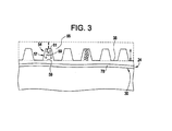
- airfoil surface 38 includes a patterned zone 47 having a plurality of raised elements, one of which is indicated at 54 that enhance aerodynamic performance for turbine bucket 24.
- Each raised element 54 includes a body portion 57 having a base portion 59 that extends to a tip portion 61.
- base portion 59 is larger than tip portion 61, it should be understood that raised element 54 can take on a variety of forms, including forms having rectangular profiles, curvilinear profiles and the like.
- a coating is applied to patterned zone 47. Coating 65 provides additional protection for each raised element 54.
- coating 65 is applied in a substantially linear layer. However, it should be understood that coating 65 could also be contoured.
- a plurality of pores 69 are created in body portion 57. Pores 69 further enhance the surface area of raised elements 54.
- patterned zone 47 is formed using a direct write (DW) process.
- the direct write process adds material to airfoil surface 38 in a predetermined pattern.
- raised elements 54 are formed from at least one of a polymer, a ceramic, a metal, and a composite. Of course other materials and composites may also be employed.
- a bond coat 78 is applied to airfoil surface 38 prior to adding patterned zone 47. Bond coat 78 enhances adhesion of the plurality of raised features 54 that are added using the DW process.
- a pattern design and material type is formulated for the DW process as indicated in block 92. That is, prior to creating patterned zone 47, the particular type of pattern and the particular material employed to form the pattern is formulated and input into a DW process application. In accordance with one aspect, the particular material(s) chosen will result in raised elements 54 including pores 69.
- bond coat 78 is added to airfoil surface 38 as indicated in block 94. After applying bond coat 78 and/or grit blasting or chemical etching is applied to improve surface roughness to enhance adhesion, surface deposits are added to airfoil surface 38 as indicated in block 96.
- airfoil surface 38 is heat-treated to consolidate or harden raised features 54 as indicated in block 98.
- need for heat-treatment is dependent upon the particular type of material used in forming the plurality of raised features.
- a partial overcoat is applied to the plurality of raised features 54 as indicated in block 100.
- the overcoat or coating is used to provide additional protection to the plurality raised features as indicated above.
- material may be removed to form additional patterns in airfoil surface 48. The material is removed using one or more known techniques such as etching, lasers and the like.
- the exemplary embodiments employs a direct write (DW) process to add material to surface portions of a turbomachine component to form a patterned zone.
- portions of the material can be selectively removed to alter/adjust the patterned zone.
- the material is selectively removed using a solvent to dissolve portions of the patterned zone, or using a laser to remove/alter portions of the patterned zone.
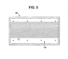
- exemplary embodiments can be employed to create a patterned zone 110 on two-dimensional (2D) surfaces such as a shroud 120 shown in FIG. 5 .
- the additional material enhances the structural stability of the turbomachine component. That is, instead of the conventional process for creating patterns on existing turbomachine components which requires removing material, the exemplary embodiments add material to the turbomachine component to enhance aerodynamic properties.
Landscapes
- Engineering & Computer Science (AREA)
- Mechanical Engineering (AREA)
- Manufacturing & Machinery (AREA)
- General Engineering & Computer Science (AREA)
- Chemical & Material Sciences (AREA)
- Materials Engineering (AREA)
- Architecture (AREA)
- Structures Of Non-Positive Displacement Pumps (AREA)
- Turbine Rotor Nozzle Sealing (AREA)
- Laser Beam Processing (AREA)
Abstract
Description
- The subject matter disclosed herein relates to the art of turbomachines and, more particularly, to a patterned turbomachine component and a method of forming a pattern on a turbomachine component.
- Turbomachine components, such as compressor blades, rotate to generate a high pressure air flow. The high pressure air flow combines with a combustion air flow to rotate turbine blades. Changes in aerodynamic properties of either the compressor blades and/or the turbine blades result in changes to overall operational characteristics of the turbomachine. It has been found that increasing a surface area of compressor and/or turbine blades leads to enhanced turbomachine operation.
- Conventional methods of increasing surface area of compressor and/or turbine blades include molding processes and etching or machining, i.e., surface removal, processes. In the molding process, patterns are formed on a mold. When cast, the patterns are formed on a surface of the compressor and/or turbine blades. The patterns are configured and disposed to increase an effective surface area and enhance aerodynamic properties of the compressor and/or turbine blades. In the etching process, chemicals, lasers or other methods are employed to remove specific portions from the surface of the compressor and/or turbine blades. As noted above, the patterns are configured and disposed to increase an effective surface area and enhance aerodynamic properties of the compressor and/or turbine blades.
- According to one aspect of the invention, a method of forming a pattern on a turbomachine component includes adding material to selected surface regions of the turbomachine component, the material is arranged in a predetermined pattern.
- According to another aspect of the invention, a turbomachine component includes a body portion having an external surface. A pattern is formed on the external surface. The pattern includes material added to the external surface through a direct write (DW) process.
- System and computer program products for adding material to selected regions of a turbomachine component are also described and claimed herein.
- The subject matter, which is regarded as the invention, is particularly pointed out and distinctly claimed in the claims at the conclusion of the specification. The foregoing and other features, and advantages of the invention are apparent from the following detailed description taken in conjunction with the accompanying drawings in which:
-
FIG. 1 is a partial, cross-sectional view of a turbomachine including a patterned turbomachine component in accordance with an exemplary embodiment; -
FIG 2 is a perspective view of the patterned turbomachine component ofFIG. 1 ; -
FIG 3 is a partial side view of the patterned turbomachine component ofFIG. 2 illustrating material added to a surface of the turbomachine component to form a pattern; -
FIG. 4 is a flow chart illustrating a method of forming a pattern on a turbomachine component in accordance with an exemplary embodiment; and -
FIG. 5 is a plan view of another patterned turbomachine component in accordance with an exemplary embodiment. - Referring to
FIG. 1 , a turbomachine constructed in accordance with an exemplary embodiment is indicated generally at 2.Turbomachine 2 includes aturbine casing 4 that houses acombustion chamber 6 and aturbine stage 8. In the exemplary embodiment shown,turbine stage 8 is a first stage. Combustion gases fromcombustion chamber 6 pass through afirst stage nozzle 10 along a hot gas path (HGP) 12 to asecond stage nozzle 14. The combustion gases drive arotor disk 20 that, in turn, drives a turbine shaft (not shown).Rotor disk 20 is arranged in awheel space area 22 ofturbomachine 2 and includes a plurality of turbine buckets, one of which is indicated at 24, mounted torotor disk 20. Eachturbine bucket 24 includes abody portion 27 that defines abase portion 30, and anairfoil portion 32.Airfoil portion 32 includes afirst end section 34 that extends to asecond end section 35 through anairfoil surface 38. The combustion gases passing alonghot gas path 12impact airfoil surface 38 pushingairfoil portion 32 circumferentially causingrotor disk 20 to rotate. - With reference to
FIGS 2 and3 , in accordance an exemplary embodiment,airfoil surface 38 includes a patternedzone 47 having a plurality of raised elements, one of which is indicated at 54 that enhance aerodynamic performance forturbine bucket 24. Each raisedelement 54 includes abody portion 57 having abase portion 59 that extends to atip portion 61. Although shown having a generally trapezoidal form withbase portion 59 being larger thantip portion 61, it should be understood that raisedelement 54 can take on a variety of forms, including forms having rectangular profiles, curvilinear profiles and the like. In accordance with one aspect of the exemplary embodiment, a coating is applied to patternedzone 47.Coating 65 provides additional protection for each raisedelement 54. In the exemplary embodiment shown,coating 65 is applied in a substantially linear layer. However, it should be understood thatcoating 65 could also be contoured. In accordance with another aspect of the exemplary embodiment, a plurality ofpores 69 are created inbody portion 57.Pores 69 further enhance the surface area of raisedelements 54. - In further accordance with the exemplary embodiment, patterned
zone 47 is formed using a direct write (DW) process. The direct write process adds material toairfoil surface 38 in a predetermined pattern. In accordance with one aspect of the exemplary embodiment, raisedelements 54 are formed from at least one of a polymer, a ceramic, a metal, and a composite. Of course other materials and composites may also be employed. As will be discussed more fully below, depending upon the material employed for raisedelements 54, prior to addingpatterned zone 47, abond coat 78 is applied toairfoil surface 38.Bond coat 78 enhances adhesion of the plurality of raisedfeatures 54 that are added using the DW process. - Reference will now be made to
FIG. 4 in describing amethod 90 of creating patternedzone 47. Initially, a pattern design and material type is formulated for the DW process as indicated inblock 92. That is, prior to creatingpatterned zone 47, the particular type of pattern and the particular material employed to form the pattern is formulated and input into a DW process application. In accordance with one aspect, the particular material(s) chosen will result in raisedelements 54 includingpores 69. At this point, if required,bond coat 78 is added toairfoil surface 38 as indicated inblock 94. After applyingbond coat 78 and/or grit blasting or chemical etching is applied to improve surface roughness to enhance adhesion, surface deposits are added toairfoil surface 38 as indicated inblock 96. After adding the surface deposits to form the plurality of raisedfeatures 54,airfoil surface 38 is heat-treated to consolidate or harden raisedfeatures 54 as indicated inblock 98. Of course, it should be understood that the need for heat-treatment is dependent upon the particular type of material used in forming the plurality of raised features. - After heat-treating, a partial overcoat is applied to the plurality of raised
features 54 as indicated inblock 100. The overcoat or coating is used to provide additional protection to the plurality raised features as indicated above. Of course the need for an overcoat or coating is also dependent on a particular type of material used in forming patternedzone 47. In addition to adding features, material may be removed to form additional patterns in airfoil surface 48. The material is removed using one or more known techniques such as etching, lasers and the like. - At this point, it should be understood that the exemplary embodiments employs a direct write (DW) process to add material to surface portions of a turbomachine component to form a patterned zone. Of course, once added, portions of the material can be selectively removed to alter/adjust the patterned zone. If desired, the material is selectively removed using a solvent to dissolve portions of the patterned zone, or using a laser to remove/alter portions of the patterned zone. In addition to providing patterns on three-dimensional (3D) surfaces such as turbine buckets described above, exemplary embodiments can be employed to create a patterned
zone 110 on two-dimensional (2D) surfaces such as ashroud 120 shown inFIG. 5 . Regardless of the surface, the additional material enhances the structural stability of the turbomachine component. That is, instead of the conventional process for creating patterns on existing turbomachine components which requires removing material, the exemplary embodiments add material to the turbomachine component to enhance aerodynamic properties. - While the invention has been described in detail in connection with only a limited number of embodiments, it should be readily understood that the invention is not limited to such disclosed embodiments. Rather, the invention can be modified to incorporate any number of variations, alterations, substitutions or equivalent arrangements not heretofore described, but which are commensurate with the spirit and scope of the invention. Additionally, while various embodiments of the invention have been described, it is to be understood that aspects of the invention may include only some of the described embodiments. Accordingly, the invention is not to be seen as limited by the foregoing description, but is only limited by the scope of the appended claims.
- Various aspects and embodiments of the present invention are defined by the following numbered clause:
- 1. A method of forming patterns on a turbomachine component, the method comprising:
- adding material to selected surface regions of the turbomachine component using a direct write (DW) process, the material being arranged in a predetermined pattern.
- 2. The method of clause 1, wherein adding material to the selected surface regions includes adding at least one of a two-dimensional structure and a three-dimensional structure to the selected surface regions.
- 3. The method of clause 1, further comprising: creating a computer drawing file that defines the predetermined pattern to be added to the selected surface regions of the turbomachine component.
- 4. The method of clause 3, further comprising: transferring the pattern directly to the turbomachine component.
- 5. The method of clause 1, further comprising: adding material with at least one of a nozzle dispensing process, thermal spray process, a soft lithography process, and a laser process.
- 6. The method of clause 1, further comprising: removing a portion of the material added to the selected surface regions.
- 7. The method of
clause 6, wherein removing the portion of the material includes dissolving, with a laser, predetermined portions of the material. - 8. The method according to clause 1, wherein the material is added to select surface regions of one of a compressor blade and a turbine blade.
- 9. A system for establishing a pattern on a turbomachine component, the system comprising:
- a central processing unit (CPU), said CPU being interconnected functionally via a system bus to:
- at least one memory device thereupon stored a set of instructions which, when executed by the CPU, causes the system to:
- add material to selected surface regions of the turbomachine component using a direct write (DW) process, the material being arranged in a predetermined pattern.
- at least one memory device thereupon stored a set of instructions which, when executed by the CPU, causes the system to:
- a central processing unit (CPU), said CPU being interconnected functionally via a system bus to:
- 10. The system according to clause 9, wherein the set of instructions, when executed by the CPU, causes the system to: add at least one of a two-dimensional structure and a three-dimensional structure to the selected surface regions.
- 11. The system according to clause 9, wherein the set of instructions, when executed by the CPU, causes the system to: transfer a pattern stored in the at least one memory device directly to the turbomachine component.
- 12. The system according to clause 9, wherein the set of instructions, when executed by the CPU, causes the system to: add material through a direct write (DW) process.
- 13. The system according to
clause 12, wherein the set of instructions, when executed by the CPU, causes the system to: add material with at least one of a nozzle dispensing process, miniature gun thermal spray process, a soft lithography process, and a laser process. - 14. The system according to clause 9, wherein the set of instructions, when executed by the CPU, causes the system to: remove a portion of the material added to the selected surface regions.
- 15. A turbomachine component comprising:
- a body portion including an external surface; and
- a pattern formed on the external surface, the pattern including material added to select portions of the external surface through a direct write (DW) process.
- 16. The turbomachine according to clause 15, further comprising:
- removing a portion of the material added to the select portions of the external surface.
- 17. The turbomachine according to clause 15, wherein the turbomachine component includes a three-dimensional (3D) surface.
- 18. The turbomachine according to clause 17, wherein the turbomachine component is one of a compressor blade and a turbine blade.
- 19. The turbomachine according to clause 15, wherein the turbomachine component includes a two-dimensional (2D) surface.
- 20. The turbomachine according to clause 19, wherein the turbomachine component is a shroud.
Claims (8)
- A method of forming patterns on a turbomachine component (24), the method comprising:adding material to selected surface regions (38) of the turbomachine component (24) using a direct write (DW) process, the material being arranged in a predetermined pattern.
- The method of claim 1, wherein adding material to the selected surface regions (38) includes adding at least one of a two-dimensional structure and a three-dimensional structure to the selected surface regions (38).
- The method of claim 1, further comprising: creating a computer drawing file that defines the predetermined pattern to be added to the selected surface regions (38) of the turbomachine component (24).
- The method of claim 3, further comprising: transferring the pattern directly to the turbomachine component.
- The method of claim 1, further comprising: adding material with at least one of a nozzle dispensing process, thermal spray process, a soft lithography process, and a laser process.
- The method of claim 1, further comprising: removing a portion of the material added to the selected surface regions (38).
- The method of claim 6, wherein removing the portion of the material includes dissolving, with a laser, predetermined portions of the material.
- The method according to claim 1, wherein the material is added to select surface regions (38) of one of a compressor blade and a turbine blade (24).
Applications Claiming Priority (1)
| Application Number | Priority Date | Filing Date | Title |
|---|---|---|---|
| US12/651,817 US20110164981A1 (en) | 2010-01-04 | 2010-01-04 | Patterned turbomachine component and method of forming a pattern on a turbomachine component |
Publications (2)
| Publication Number | Publication Date |
|---|---|
| EP2353753A1 true EP2353753A1 (en) | 2011-08-10 |
| EP2353753B1 EP2353753B1 (en) | 2013-04-17 |
Family
ID=44168252
Family Applications (1)
| Application Number | Title | Priority Date | Filing Date |
|---|---|---|---|
| EP10195906.2A Not-in-force EP2353753B1 (en) | 2010-01-04 | 2010-12-20 | Method of forming a pattern on a turbomachine component |
Country Status (4)
| Country | Link |
|---|---|
| US (1) | US20110164981A1 (en) |
| EP (1) | EP2353753B1 (en) |
| JP (1) | JP5795712B2 (en) |
| CN (1) | CN102116176B (en) |
Families Citing this family (7)
| Publication number | Priority date | Publication date | Assignee | Title |
|---|---|---|---|---|
| US8632327B2 (en) * | 2011-11-28 | 2014-01-21 | General Electric Company | Apparatus to apply a variable surface texture on an airfoil |
| US9022743B2 (en) * | 2011-11-30 | 2015-05-05 | United Technologies Corporation | Segmented thermally insulating coating |
| US9289917B2 (en) | 2013-10-01 | 2016-03-22 | General Electric Company | Method for 3-D printing a pattern for the surface of a turbine shroud |
| US10450867B2 (en) * | 2016-02-12 | 2019-10-22 | General Electric Company | Riblets for a flowpath surface of a turbomachine |
| EP3450684A1 (en) * | 2017-09-04 | 2019-03-06 | Siemens Aktiengesellschaft | Method of manufacturing a component |
| US12304614B2 (en) * | 2023-06-13 | 2025-05-20 | General Electric Company | Composite airfoil assembly and method of forming a composite airfoil assembly |
| TWI871703B (en) * | 2023-07-19 | 2025-02-01 | 宏碁股份有限公司 | Axial-flow heat-dissipation fan |
Citations (4)
| Publication number | Priority date | Publication date | Assignee | Title |
|---|---|---|---|---|
| US6203021B1 (en) * | 1996-12-10 | 2001-03-20 | Chromalloy Gas Turbine Corporation | Abradable seal having a cut pattern |
| US20040115351A1 (en) * | 2002-12-17 | 2004-06-17 | Yuk-Chiu Lau | High temperature abradable coatings |
| EP1645655A1 (en) * | 2004-10-05 | 2006-04-12 | Siemens Aktiengesellschaft | Coated substrate and coating method |
| EP1952932A2 (en) * | 2007-01-31 | 2008-08-06 | General Electric Company | Laser net shape manufacturing using an adaptive toolpath deposition method |
Family Cites Families (31)
| Publication number | Priority date | Publication date | Assignee | Title |
|---|---|---|---|---|
| US4339282A (en) * | 1981-06-03 | 1982-07-13 | United Technologies Corporation | Method and composition for removing aluminide coatings from nickel superalloys |
| US4720239A (en) * | 1982-10-22 | 1988-01-19 | Owczarek Jerzy A | Stator blades of turbomachines |
| US4986496A (en) * | 1985-05-31 | 1991-01-22 | Minnesota Mining And Manufacturing | Drag reduction article |
| JPH01219301A (en) * | 1988-02-26 | 1989-09-01 | Hitachi Ltd | Moving blade for steam turbine |
| DE4120305C1 (en) * | 1991-06-20 | 1992-08-27 | Mtu Muenchen Gmbh | |
| US5419971A (en) * | 1993-03-03 | 1995-05-30 | General Electric Company | Enhanced thermal barrier coating system |
| US6200439B1 (en) * | 1998-11-05 | 2001-03-13 | General Electric Company | Tool for electrochemical machining |
| US6303193B1 (en) * | 1998-11-05 | 2001-10-16 | General Electric Company | Process for fabricating a tool used in electrochemical machining |
| US6267902B1 (en) * | 1998-12-15 | 2001-07-31 | General Electric Company | Process for removing a coating from a hole in a metal substrate |
| US6290461B1 (en) * | 1999-08-16 | 2001-09-18 | General Electric Company | Method and tool for electrochemical machining |
| US6387242B1 (en) * | 1999-08-16 | 2002-05-14 | General Electric Company | Method and tool for electrochemical machining |
| US6234752B1 (en) * | 1999-08-16 | 2001-05-22 | General Electric Company | Method and tool for electrochemical machining |
| US6267868B1 (en) * | 1999-08-16 | 2001-07-31 | General Electric Company | Method and tool for electrochemical machining |
| US6352636B1 (en) * | 1999-10-18 | 2002-03-05 | General Electric Company | Electrochemical system and process for stripping metallic coatings |
| US6420178B1 (en) * | 2000-09-20 | 2002-07-16 | General Electric Company | High throughput screening method, array assembly and system |
| US6863738B2 (en) * | 2001-01-29 | 2005-03-08 | General Electric Company | Method for removing oxides and coatings from a substrate |
| US6846574B2 (en) * | 2001-05-16 | 2005-01-25 | Siemens Westinghouse Power Corporation | Honeycomb structure thermal barrier coating |
| US6380512B1 (en) * | 2001-10-09 | 2002-04-30 | Chromalloy Gas Turbine Corporation | Method for removing coating material from a cooling hole of a gas turbine engine component |
| JP3958040B2 (en) * | 2001-12-17 | 2007-08-15 | 京セラ株式会社 | Manufacturing method of ceramic nozzle |
| US6921014B2 (en) * | 2002-05-07 | 2005-07-26 | General Electric Company | Method for forming a channel on the surface of a metal substrate |
| US20050003172A1 (en) * | 2002-12-17 | 2005-01-06 | General Electric Company | 7FAstage 1 abradable coatings and method for making same |
| US20040121182A1 (en) * | 2002-12-23 | 2004-06-24 | Hardwicke Canan Uslu | Method and composition to repair and build structures |
| FR2853572B1 (en) * | 2003-04-10 | 2005-05-27 | Snecma Moteurs | METHOD FOR MANUFACTURING A HOLLOW MECHANICAL WELDING-DIFFUSION MECHANICAL PIECE AND SUPERPLASTIC FORMING |
| US7351290B2 (en) * | 2003-07-17 | 2008-04-01 | General Electric Company | Robotic pen |
| US7302990B2 (en) * | 2004-05-06 | 2007-12-04 | General Electric Company | Method of forming concavities in the surface of a metal component, and related processes and articles |
| JP2006131997A (en) * | 2004-10-29 | 2006-05-25 | United Technol Corp <Utc> | Method for repairing workpiece |
| US7360437B2 (en) * | 2005-06-28 | 2008-04-22 | General Electric Company | Devices for evaluating material properties, and related processes |
| US20070003416A1 (en) * | 2005-06-30 | 2007-01-04 | General Electric Company | Niobium silicide-based turbine components, and related methods for laser deposition |
| US20080274336A1 (en) * | 2006-12-01 | 2008-11-06 | Siemens Power Generation, Inc. | High temperature insulation with enhanced abradability |
| US20080145694A1 (en) * | 2006-12-19 | 2008-06-19 | David Vincent Bucci | Thermal barrier coating system and method for coating a component |
| US20080264897A1 (en) * | 2007-04-30 | 2008-10-30 | Canan Uslu Hardwicke | Turbine component pattern forming method |
-
2010
- 2010-01-04 US US12/651,817 patent/US20110164981A1/en not_active Abandoned
- 2010-12-20 EP EP10195906.2A patent/EP2353753B1/en not_active Not-in-force
- 2010-12-27 JP JP2010289136A patent/JP5795712B2/en not_active Expired - Fee Related
-
2011
- 2011-01-04 CN CN201110008844.7A patent/CN102116176B/en not_active Expired - Fee Related
Patent Citations (4)
| Publication number | Priority date | Publication date | Assignee | Title |
|---|---|---|---|---|
| US6203021B1 (en) * | 1996-12-10 | 2001-03-20 | Chromalloy Gas Turbine Corporation | Abradable seal having a cut pattern |
| US20040115351A1 (en) * | 2002-12-17 | 2004-06-17 | Yuk-Chiu Lau | High temperature abradable coatings |
| EP1645655A1 (en) * | 2004-10-05 | 2006-04-12 | Siemens Aktiengesellschaft | Coated substrate and coating method |
| EP1952932A2 (en) * | 2007-01-31 | 2008-08-06 | General Electric Company | Laser net shape manufacturing using an adaptive toolpath deposition method |
Also Published As
| Publication number | Publication date |
|---|---|
| EP2353753B1 (en) | 2013-04-17 |
| CN102116176A (en) | 2011-07-06 |
| JP2011137466A (en) | 2011-07-14 |
| JP5795712B2 (en) | 2015-10-14 |
| CN102116176B (en) | 2015-07-22 |
| US20110164981A1 (en) | 2011-07-07 |
Similar Documents
| Publication | Publication Date | Title |
|---|---|---|
| EP2353753A1 (en) | Method of forming a pattern on a turbomachine component | |
| JP6348965B2 (en) | Additive manufacturing method for adding structures in cooling holes | |
| US20080317602A1 (en) | Article having a vibration damping coating and a method of applying a vibration damping coating to an article | |
| JP2014114810A (en) | Airfoil and method for cooling airfoil platform | |
| JP4307814B2 (en) | Transonic airfoils with reduced shock waves | |
| JP2008106755A (en) | Blade shape for compressor | |
| US20130149163A1 (en) | Method for Reducing Stress on Blade Tips | |
| JP6931991B2 (en) | How to manage moisture in steam turbines, steam turbine nozzles, and steam turbines | |
| CN1626696A (en) | Protection mask for the surface treatment of blades for turbine engines | |
| WO2014099814A1 (en) | Robust turbine blades | |
| JP2009264378A (en) | Shape for turbine bucket tip shroud | |
| US20160243654A1 (en) | Component repair using confined laser drilling | |
| JP2022519571A (en) | Controlling the degree of TBC sheet crushing | |
| EP2882570B1 (en) | Post processing of components that are laser peened | |
| Krain et al. | Improved high pressure ratio centrifugal compressor | |
| EP3282034A1 (en) | Aluminum fan blade tip prepared for thermal spray deposition of abrasive by laser ablation | |
| Gonzalez et al. | On the numerical simulation of turbine blade tangling after a shaft failure | |
| JP2015501222A (en) | How to repair surface damage on turbomachine parts | |
| JP7539915B2 (en) | Protecting and Improving Thermal Barrier Coating Integrity Through Lithography | |
| Williams et al. | A study of large tip clearance flows in an axial compressor blade row | |
| EL-Saied et al. | Erosion of an Axial Transonic Fan due to dust ingestion | |
| JP2015518542A (en) | Turbomachine parts with functional coating | |
| Bohn et al. | Influence of Stator Clocking on the Unsteady 3-Dimensional Flow in a 2-Stage Turbine | |
| Phillipsen | A simple inverse cascade design method | |
| Mayenberger et al. | Aerodynamic design of abradable liners with integrated endwall treatments for axial compressor rotors |
Legal Events
| Date | Code | Title | Description |
|---|---|---|---|
| PUAI | Public reference made under article 153(3) epc to a published international application that has entered the european phase |
Free format text: ORIGINAL CODE: 0009012 |
|
| AK | Designated contracting states |
Kind code of ref document: A1 Designated state(s): AL AT BE BG CH CY CZ DE DK EE ES FI FR GB GR HR HU IE IS IT LI LT LU LV MC MK MT NL NO PL PT RO RS SE SI SK SM TR |
|
| AX | Request for extension of the european patent |
Extension state: BA ME |
|
| 17P | Request for examination filed |
Effective date: 20120210 |
|
| 17Q | First examination report despatched |
Effective date: 20120601 |
|
| GRAP | Despatch of communication of intention to grant a patent |
Free format text: ORIGINAL CODE: EPIDOSNIGR1 |
|
| GRAS | Grant fee paid |
Free format text: ORIGINAL CODE: EPIDOSNIGR3 |
|
| GRAA | (expected) grant |
Free format text: ORIGINAL CODE: 0009210 |
|
| AK | Designated contracting states |
Kind code of ref document: B1 Designated state(s): AL AT BE BG CH CY CZ DE DK EE ES FI FR GB GR HR HU IE IS IT LI LT LU LV MC MK MT NL NO PL PT RO RS SE SI SK SM TR |
|
| REG | Reference to a national code |
Ref country code: GB Ref legal event code: FG4D |
|
| REG | Reference to a national code |
Ref country code: CH Ref legal event code: EP |
|
| REG | Reference to a national code |
Ref country code: IE Ref legal event code: FG4D |
|
| REG | Reference to a national code |
Ref country code: AT Ref legal event code: REF Ref document number: 606931 Country of ref document: AT Kind code of ref document: T Effective date: 20130515 |
|
| REG | Reference to a national code |
Ref country code: DE Ref legal event code: R096 Ref document number: 602010006241 Country of ref document: DE Effective date: 20130613 |
|
| REG | Reference to a national code |
Ref country code: AT Ref legal event code: MK05 Ref document number: 606931 Country of ref document: AT Kind code of ref document: T Effective date: 20130417 |
|
| REG | Reference to a national code |
Ref country code: LT Ref legal event code: MG4D |
|
| REG | Reference to a national code |
Ref country code: NL Ref legal event code: VDEP Effective date: 20130417 |
|
| PG25 | Lapsed in a contracting state [announced via postgrant information from national office to epo] |
Ref country code: LT Free format text: LAPSE BECAUSE OF FAILURE TO SUBMIT A TRANSLATION OF THE DESCRIPTION OR TO PAY THE FEE WITHIN THE PRESCRIBED TIME-LIMIT Effective date: 20130417 Ref country code: SE Free format text: LAPSE BECAUSE OF FAILURE TO SUBMIT A TRANSLATION OF THE DESCRIPTION OR TO PAY THE FEE WITHIN THE PRESCRIBED TIME-LIMIT Effective date: 20130417 Ref country code: SI Free format text: LAPSE BECAUSE OF FAILURE TO SUBMIT A TRANSLATION OF THE DESCRIPTION OR TO PAY THE FEE WITHIN THE PRESCRIBED TIME-LIMIT Effective date: 20130417 Ref country code: GR Free format text: LAPSE BECAUSE OF FAILURE TO SUBMIT A TRANSLATION OF THE DESCRIPTION OR TO PAY THE FEE WITHIN THE PRESCRIBED TIME-LIMIT Effective date: 20130718 Ref country code: AT Free format text: LAPSE BECAUSE OF FAILURE TO SUBMIT A TRANSLATION OF THE DESCRIPTION OR TO PAY THE FEE WITHIN THE PRESCRIBED TIME-LIMIT Effective date: 20130417 Ref country code: IS Free format text: LAPSE BECAUSE OF FAILURE TO SUBMIT A TRANSLATION OF THE DESCRIPTION OR TO PAY THE FEE WITHIN THE PRESCRIBED TIME-LIMIT Effective date: 20130817 Ref country code: FI Free format text: LAPSE BECAUSE OF FAILURE TO SUBMIT A TRANSLATION OF THE DESCRIPTION OR TO PAY THE FEE WITHIN THE PRESCRIBED TIME-LIMIT Effective date: 20130417 Ref country code: BE Free format text: LAPSE BECAUSE OF FAILURE TO SUBMIT A TRANSLATION OF THE DESCRIPTION OR TO PAY THE FEE WITHIN THE PRESCRIBED TIME-LIMIT Effective date: 20130417 Ref country code: NO Free format text: LAPSE BECAUSE OF FAILURE TO SUBMIT A TRANSLATION OF THE DESCRIPTION OR TO PAY THE FEE WITHIN THE PRESCRIBED TIME-LIMIT Effective date: 20130717 Ref country code: PT Free format text: LAPSE BECAUSE OF FAILURE TO SUBMIT A TRANSLATION OF THE DESCRIPTION OR TO PAY THE FEE WITHIN THE PRESCRIBED TIME-LIMIT Effective date: 20130819 Ref country code: ES Free format text: LAPSE BECAUSE OF FAILURE TO SUBMIT A TRANSLATION OF THE DESCRIPTION OR TO PAY THE FEE WITHIN THE PRESCRIBED TIME-LIMIT Effective date: 20130728 |
|
| PG25 | Lapsed in a contracting state [announced via postgrant information from national office to epo] |
Ref country code: PL Free format text: LAPSE BECAUSE OF FAILURE TO SUBMIT A TRANSLATION OF THE DESCRIPTION OR TO PAY THE FEE WITHIN THE PRESCRIBED TIME-LIMIT Effective date: 20130417 Ref country code: BG Free format text: LAPSE BECAUSE OF FAILURE TO SUBMIT A TRANSLATION OF THE DESCRIPTION OR TO PAY THE FEE WITHIN THE PRESCRIBED TIME-LIMIT Effective date: 20130717 Ref country code: LV Free format text: LAPSE BECAUSE OF FAILURE TO SUBMIT A TRANSLATION OF THE DESCRIPTION OR TO PAY THE FEE WITHIN THE PRESCRIBED TIME-LIMIT Effective date: 20130417 Ref country code: HR Free format text: LAPSE BECAUSE OF FAILURE TO SUBMIT A TRANSLATION OF THE DESCRIPTION OR TO PAY THE FEE WITHIN THE PRESCRIBED TIME-LIMIT Effective date: 20130417 Ref country code: CY Free format text: LAPSE BECAUSE OF FAILURE TO SUBMIT A TRANSLATION OF THE DESCRIPTION OR TO PAY THE FEE WITHIN THE PRESCRIBED TIME-LIMIT Effective date: 20130417 Ref country code: RS Free format text: LAPSE BECAUSE OF FAILURE TO SUBMIT A TRANSLATION OF THE DESCRIPTION OR TO PAY THE FEE WITHIN THE PRESCRIBED TIME-LIMIT Effective date: 20130417 |
|
| PG25 | Lapsed in a contracting state [announced via postgrant information from national office to epo] |
Ref country code: EE Free format text: LAPSE BECAUSE OF FAILURE TO SUBMIT A TRANSLATION OF THE DESCRIPTION OR TO PAY THE FEE WITHIN THE PRESCRIBED TIME-LIMIT Effective date: 20130417 Ref country code: DK Free format text: LAPSE BECAUSE OF FAILURE TO SUBMIT A TRANSLATION OF THE DESCRIPTION OR TO PAY THE FEE WITHIN THE PRESCRIBED TIME-LIMIT Effective date: 20130417 Ref country code: CZ Free format text: LAPSE BECAUSE OF FAILURE TO SUBMIT A TRANSLATION OF THE DESCRIPTION OR TO PAY THE FEE WITHIN THE PRESCRIBED TIME-LIMIT Effective date: 20130417 Ref country code: SK Free format text: LAPSE BECAUSE OF FAILURE TO SUBMIT A TRANSLATION OF THE DESCRIPTION OR TO PAY THE FEE WITHIN THE PRESCRIBED TIME-LIMIT Effective date: 20130417 |
|
| PLBE | No opposition filed within time limit |
Free format text: ORIGINAL CODE: 0009261 |
|
| STAA | Information on the status of an ep patent application or granted ep patent |
Free format text: STATUS: NO OPPOSITION FILED WITHIN TIME LIMIT |
|
| PG25 | Lapsed in a contracting state [announced via postgrant information from national office to epo] |
Ref country code: NL Free format text: LAPSE BECAUSE OF FAILURE TO SUBMIT A TRANSLATION OF THE DESCRIPTION OR TO PAY THE FEE WITHIN THE PRESCRIBED TIME-LIMIT Effective date: 20130417 Ref country code: RO Free format text: LAPSE BECAUSE OF FAILURE TO SUBMIT A TRANSLATION OF THE DESCRIPTION OR TO PAY THE FEE WITHIN THE PRESCRIBED TIME-LIMIT Effective date: 20130417 Ref country code: IT Free format text: LAPSE BECAUSE OF FAILURE TO SUBMIT A TRANSLATION OF THE DESCRIPTION OR TO PAY THE FEE WITHIN THE PRESCRIBED TIME-LIMIT Effective date: 20130417 |
|
| 26N | No opposition filed |
Effective date: 20140120 |
|
| REG | Reference to a national code |
Ref country code: DE Ref legal event code: R097 Ref document number: 602010006241 Country of ref document: DE Effective date: 20140120 |
|
| PG25 | Lapsed in a contracting state [announced via postgrant information from national office to epo] |
Ref country code: LU Free format text: LAPSE BECAUSE OF FAILURE TO SUBMIT A TRANSLATION OF THE DESCRIPTION OR TO PAY THE FEE WITHIN THE PRESCRIBED TIME-LIMIT Effective date: 20131220 |
|
| REG | Reference to a national code |
Ref country code: IE Ref legal event code: MM4A |
|
| PG25 | Lapsed in a contracting state [announced via postgrant information from national office to epo] |
Ref country code: IE Free format text: LAPSE BECAUSE OF NON-PAYMENT OF DUE FEES Effective date: 20131220 |
|
| PG25 | Lapsed in a contracting state [announced via postgrant information from national office to epo] |
Ref country code: MC Free format text: LAPSE BECAUSE OF FAILURE TO SUBMIT A TRANSLATION OF THE DESCRIPTION OR TO PAY THE FEE WITHIN THE PRESCRIBED TIME-LIMIT Effective date: 20130417 |
|
| PG25 | Lapsed in a contracting state [announced via postgrant information from national office to epo] |
Ref country code: SM Free format text: LAPSE BECAUSE OF FAILURE TO SUBMIT A TRANSLATION OF THE DESCRIPTION OR TO PAY THE FEE WITHIN THE PRESCRIBED TIME-LIMIT Effective date: 20130417 |
|
| PG25 | Lapsed in a contracting state [announced via postgrant information from national office to epo] |
Ref country code: TR Free format text: LAPSE BECAUSE OF FAILURE TO SUBMIT A TRANSLATION OF THE DESCRIPTION OR TO PAY THE FEE WITHIN THE PRESCRIBED TIME-LIMIT Effective date: 20130417 |
|
| PG25 | Lapsed in a contracting state [announced via postgrant information from national office to epo] |
Ref country code: HU Free format text: LAPSE BECAUSE OF FAILURE TO SUBMIT A TRANSLATION OF THE DESCRIPTION OR TO PAY THE FEE WITHIN THE PRESCRIBED TIME-LIMIT; INVALID AB INITIO Effective date: 20101220 Ref country code: MK Free format text: LAPSE BECAUSE OF FAILURE TO SUBMIT A TRANSLATION OF THE DESCRIPTION OR TO PAY THE FEE WITHIN THE PRESCRIBED TIME-LIMIT Effective date: 20130417 |
|
| REG | Reference to a national code |
Ref country code: CH Ref legal event code: PL |
|
| GBPC | Gb: european patent ceased through non-payment of renewal fee |
Effective date: 20141220 |
|
| PG25 | Lapsed in a contracting state [announced via postgrant information from national office to epo] |
Ref country code: MT Free format text: LAPSE BECAUSE OF FAILURE TO SUBMIT A TRANSLATION OF THE DESCRIPTION OR TO PAY THE FEE WITHIN THE PRESCRIBED TIME-LIMIT Effective date: 20130417 |
|
| PG25 | Lapsed in a contracting state [announced via postgrant information from national office to epo] |
Ref country code: LI Free format text: LAPSE BECAUSE OF NON-PAYMENT OF DUE FEES Effective date: 20141231 Ref country code: CH Free format text: LAPSE BECAUSE OF NON-PAYMENT OF DUE FEES Effective date: 20141231 Ref country code: GB Free format text: LAPSE BECAUSE OF NON-PAYMENT OF DUE FEES Effective date: 20141220 |
|
| REG | Reference to a national code |
Ref country code: FR Ref legal event code: PLFP Year of fee payment: 6 |
|
| REG | Reference to a national code |
Ref country code: FR Ref legal event code: PLFP Year of fee payment: 7 |
|
| PGFP | Annual fee paid to national office [announced via postgrant information from national office to epo] |
Ref country code: FR Payment date: 20161227 Year of fee payment: 7 |
|
| PGFP | Annual fee paid to national office [announced via postgrant information from national office to epo] |
Ref country code: DE Payment date: 20161229 Year of fee payment: 7 |
|
| REG | Reference to a national code |
Ref country code: DE Ref legal event code: R119 Ref document number: 602010006241 Country of ref document: DE |
|
| REG | Reference to a national code |
Ref country code: FR Ref legal event code: ST Effective date: 20180831 |
|
| PG25 | Lapsed in a contracting state [announced via postgrant information from national office to epo] |
Ref country code: FR Free format text: LAPSE BECAUSE OF NON-PAYMENT OF DUE FEES Effective date: 20180102 Ref country code: DE Free format text: LAPSE BECAUSE OF NON-PAYMENT OF DUE FEES Effective date: 20180703 Ref country code: AL Free format text: LAPSE BECAUSE OF FAILURE TO SUBMIT A TRANSLATION OF THE DESCRIPTION OR TO PAY THE FEE WITHIN THE PRESCRIBED TIME-LIMIT Effective date: 20130417 |