EP2353549A1 - Articulating humeral head prosthesis - Google Patents
Articulating humeral head prosthesis Download PDFInfo
- Publication number
- EP2353549A1 EP2353549A1 EP11152183A EP11152183A EP2353549A1 EP 2353549 A1 EP2353549 A1 EP 2353549A1 EP 11152183 A EP11152183 A EP 11152183A EP 11152183 A EP11152183 A EP 11152183A EP 2353549 A1 EP2353549 A1 EP 2353549A1
- Authority
- EP
- European Patent Office
- Prior art keywords
- humeral head
- prosthesis
- component
- cap
- humeral
- Prior art date
- Legal status (The legal status is an assumption and is not a legal conclusion. Google has not performed a legal analysis and makes no representation as to the accuracy of the status listed.)
- Granted
Links
Images













Classifications
-
- A—HUMAN NECESSITIES
- A61—MEDICAL OR VETERINARY SCIENCE; HYGIENE
- A61F—FILTERS IMPLANTABLE INTO BLOOD VESSELS; PROSTHESES; DEVICES PROVIDING PATENCY TO, OR PREVENTING COLLAPSING OF, TUBULAR STRUCTURES OF THE BODY, e.g. STENTS; ORTHOPAEDIC, NURSING OR CONTRACEPTIVE DEVICES; FOMENTATION; TREATMENT OR PROTECTION OF EYES OR EARS; BANDAGES, DRESSINGS OR ABSORBENT PADS; FIRST-AID KITS
- A61F2/00—Filters implantable into blood vessels; Prostheses, i.e. artificial substitutes or replacements for parts of the body; Appliances for connecting them with the body; Devices providing patency to, or preventing collapsing of, tubular structures of the body, e.g. stents
- A61F2/02—Prostheses implantable into the body
- A61F2/30—Joints
- A61F2/46—Special tools for implanting artificial joints
- A61F2/4603—Special tools for implanting artificial joints for insertion or extraction of endoprosthetic joints or of accessories thereof
- A61F2/4612—Special tools for implanting artificial joints for insertion or extraction of endoprosthetic joints or of accessories thereof of shoulders
-
- A—HUMAN NECESSITIES
- A61—MEDICAL OR VETERINARY SCIENCE; HYGIENE
- A61B—DIAGNOSIS; SURGERY; IDENTIFICATION
- A61B17/00—Surgical instruments, devices or methods
- A61B17/16—Instruments for performing osteoclasis; Drills or chisels for bones; Trepans
- A61B17/1662—Instruments for performing osteoclasis; Drills or chisels for bones; Trepans for particular parts of the body
- A61B17/1684—Instruments for performing osteoclasis; Drills or chisels for bones; Trepans for particular parts of the body for the shoulder
-
- A—HUMAN NECESSITIES
- A61—MEDICAL OR VETERINARY SCIENCE; HYGIENE
- A61B—DIAGNOSIS; SURGERY; IDENTIFICATION
- A61B17/00—Surgical instruments, devices or methods
- A61B17/16—Instruments for performing osteoclasis; Drills or chisels for bones; Trepans
- A61B17/17—Guides or aligning means for drills, mills, pins or wires
- A61B17/1739—Guides or aligning means for drills, mills, pins or wires specially adapted for particular parts of the body
- A61B17/1778—Guides or aligning means for drills, mills, pins or wires specially adapted for particular parts of the body for the shoulder
-
- A—HUMAN NECESSITIES
- A61—MEDICAL OR VETERINARY SCIENCE; HYGIENE
- A61F—FILTERS IMPLANTABLE INTO BLOOD VESSELS; PROSTHESES; DEVICES PROVIDING PATENCY TO, OR PREVENTING COLLAPSING OF, TUBULAR STRUCTURES OF THE BODY, e.g. STENTS; ORTHOPAEDIC, NURSING OR CONTRACEPTIVE DEVICES; FOMENTATION; TREATMENT OR PROTECTION OF EYES OR EARS; BANDAGES, DRESSINGS OR ABSORBENT PADS; FIRST-AID KITS
- A61F2/00—Filters implantable into blood vessels; Prostheses, i.e. artificial substitutes or replacements for parts of the body; Appliances for connecting them with the body; Devices providing patency to, or preventing collapsing of, tubular structures of the body, e.g. stents
- A61F2/02—Prostheses implantable into the body
- A61F2/30—Joints
- A61F2/40—Joints for shoulders
- A61F2/4003—Replacing only the epiphyseal or metaphyseal parts of the humerus, i.e. endoprosthesis not comprising an entire humeral shaft
-
- A—HUMAN NECESSITIES
- A61—MEDICAL OR VETERINARY SCIENCE; HYGIENE
- A61B—DIAGNOSIS; SURGERY; IDENTIFICATION
- A61B17/00—Surgical instruments, devices or methods
- A61B17/16—Instruments for performing osteoclasis; Drills or chisels for bones; Trepans
- A61B17/1613—Component parts
- A61B17/1615—Drill bits, i.e. rotating tools extending from a handpiece to contact the worked material
-
- A—HUMAN NECESSITIES
- A61—MEDICAL OR VETERINARY SCIENCE; HYGIENE
- A61B—DIAGNOSIS; SURGERY; IDENTIFICATION
- A61B17/00—Surgical instruments, devices or methods
- A61B17/28—Surgical forceps
- A61B17/29—Forceps for use in minimally invasive surgery
-
- A—HUMAN NECESSITIES
- A61—MEDICAL OR VETERINARY SCIENCE; HYGIENE
- A61B—DIAGNOSIS; SURGERY; IDENTIFICATION
- A61B17/00—Surgical instruments, devices or methods
- A61B17/56—Surgical instruments or methods for treatment of bones or joints; Devices specially adapted therefor
- A61B17/58—Surgical instruments or methods for treatment of bones or joints; Devices specially adapted therefor for osteosynthesis, e.g. bone plates, screws or setting implements
- A61B17/68—Internal fixation devices, including fasteners and spinal fixators, even if a part thereof projects from the skin
- A61B17/84—Fasteners therefor or fasteners being internal fixation devices
- A61B17/86—Pins or screws or threaded wires; nuts therefor
-
- A—HUMAN NECESSITIES
- A61—MEDICAL OR VETERINARY SCIENCE; HYGIENE
- A61B—DIAGNOSIS; SURGERY; IDENTIFICATION
- A61B17/00—Surgical instruments, devices or methods
- A61B17/28—Surgical forceps
- A61B17/29—Forceps for use in minimally invasive surgery
- A61B2017/2926—Details of heads or jaws
- A61B2017/2932—Transmission of forces to jaw members
-
- A—HUMAN NECESSITIES
- A61—MEDICAL OR VETERINARY SCIENCE; HYGIENE
- A61B—DIAGNOSIS; SURGERY; IDENTIFICATION
- A61B17/00—Surgical instruments, devices or methods
- A61B17/30—Surgical pincettes, i.e. surgical tweezers without pivotal connections
- A61B2017/305—Tweezer like handles with tubular extensions, inner slidable actuating members and distal tools, e.g. microsurgical instruments
-
- A—HUMAN NECESSITIES
- A61—MEDICAL OR VETERINARY SCIENCE; HYGIENE
- A61F—FILTERS IMPLANTABLE INTO BLOOD VESSELS; PROSTHESES; DEVICES PROVIDING PATENCY TO, OR PREVENTING COLLAPSING OF, TUBULAR STRUCTURES OF THE BODY, e.g. STENTS; ORTHOPAEDIC, NURSING OR CONTRACEPTIVE DEVICES; FOMENTATION; TREATMENT OR PROTECTION OF EYES OR EARS; BANDAGES, DRESSINGS OR ABSORBENT PADS; FIRST-AID KITS
- A61F2/00—Filters implantable into blood vessels; Prostheses, i.e. artificial substitutes or replacements for parts of the body; Appliances for connecting them with the body; Devices providing patency to, or preventing collapsing of, tubular structures of the body, e.g. stents
- A61F2/02—Prostheses implantable into the body
- A61F2/30—Joints
- A61F2002/30001—Additional features of subject-matter classified in A61F2/28, A61F2/30 and subgroups thereof
- A61F2002/30316—The prosthesis having different structural features at different locations within the same prosthesis; Connections between prosthetic parts; Special structural features of bone or joint prostheses not otherwise provided for
- A61F2002/30329—Connections or couplings between prosthetic parts, e.g. between modular parts; Connecting elements
- A61F2002/30433—Connections or couplings between prosthetic parts, e.g. between modular parts; Connecting elements using additional screws, bolts, dowels, rivets or washers e.g. connecting screws
-
- A—HUMAN NECESSITIES
- A61—MEDICAL OR VETERINARY SCIENCE; HYGIENE
- A61F—FILTERS IMPLANTABLE INTO BLOOD VESSELS; PROSTHESES; DEVICES PROVIDING PATENCY TO, OR PREVENTING COLLAPSING OF, TUBULAR STRUCTURES OF THE BODY, e.g. STENTS; ORTHOPAEDIC, NURSING OR CONTRACEPTIVE DEVICES; FOMENTATION; TREATMENT OR PROTECTION OF EYES OR EARS; BANDAGES, DRESSINGS OR ABSORBENT PADS; FIRST-AID KITS
- A61F2/00—Filters implantable into blood vessels; Prostheses, i.e. artificial substitutes or replacements for parts of the body; Appliances for connecting them with the body; Devices providing patency to, or preventing collapsing of, tubular structures of the body, e.g. stents
- A61F2/02—Prostheses implantable into the body
- A61F2/30—Joints
- A61F2002/30001—Additional features of subject-matter classified in A61F2/28, A61F2/30 and subgroups thereof
- A61F2002/30316—The prosthesis having different structural features at different locations within the same prosthesis; Connections between prosthetic parts; Special structural features of bone or joint prostheses not otherwise provided for
- A61F2002/30329—Connections or couplings between prosthetic parts, e.g. between modular parts; Connecting elements
- A61F2002/30476—Connections or couplings between prosthetic parts, e.g. between modular parts; Connecting elements locked by an additional locking mechanism
- A61F2002/30507—Connections or couplings between prosthetic parts, e.g. between modular parts; Connecting elements locked by an additional locking mechanism using a threaded locking member, e.g. a locking screw or a set screw
-
- A—HUMAN NECESSITIES
- A61—MEDICAL OR VETERINARY SCIENCE; HYGIENE
- A61F—FILTERS IMPLANTABLE INTO BLOOD VESSELS; PROSTHESES; DEVICES PROVIDING PATENCY TO, OR PREVENTING COLLAPSING OF, TUBULAR STRUCTURES OF THE BODY, e.g. STENTS; ORTHOPAEDIC, NURSING OR CONTRACEPTIVE DEVICES; FOMENTATION; TREATMENT OR PROTECTION OF EYES OR EARS; BANDAGES, DRESSINGS OR ABSORBENT PADS; FIRST-AID KITS
- A61F2/00—Filters implantable into blood vessels; Prostheses, i.e. artificial substitutes or replacements for parts of the body; Appliances for connecting them with the body; Devices providing patency to, or preventing collapsing of, tubular structures of the body, e.g. stents
- A61F2/02—Prostheses implantable into the body
- A61F2/30—Joints
- A61F2002/30001—Additional features of subject-matter classified in A61F2/28, A61F2/30 and subgroups thereof
- A61F2002/30316—The prosthesis having different structural features at different locations within the same prosthesis; Connections between prosthetic parts; Special structural features of bone or joint prostheses not otherwise provided for
- A61F2002/30535—Special structural features of bone or joint prostheses not otherwise provided for
- A61F2002/30537—Special structural features of bone or joint prostheses not otherwise provided for adjustable
- A61F2002/30538—Special structural features of bone or joint prostheses not otherwise provided for adjustable for adjusting angular orientation
-
- A—HUMAN NECESSITIES
- A61—MEDICAL OR VETERINARY SCIENCE; HYGIENE
- A61F—FILTERS IMPLANTABLE INTO BLOOD VESSELS; PROSTHESES; DEVICES PROVIDING PATENCY TO, OR PREVENTING COLLAPSING OF, TUBULAR STRUCTURES OF THE BODY, e.g. STENTS; ORTHOPAEDIC, NURSING OR CONTRACEPTIVE DEVICES; FOMENTATION; TREATMENT OR PROTECTION OF EYES OR EARS; BANDAGES, DRESSINGS OR ABSORBENT PADS; FIRST-AID KITS
- A61F2/00—Filters implantable into blood vessels; Prostheses, i.e. artificial substitutes or replacements for parts of the body; Appliances for connecting them with the body; Devices providing patency to, or preventing collapsing of, tubular structures of the body, e.g. stents
- A61F2/02—Prostheses implantable into the body
- A61F2/30—Joints
- A61F2002/30001—Additional features of subject-matter classified in A61F2/28, A61F2/30 and subgroups thereof
- A61F2002/30316—The prosthesis having different structural features at different locations within the same prosthesis; Connections between prosthetic parts; Special structural features of bone or joint prostheses not otherwise provided for
- A61F2002/30535—Special structural features of bone or joint prostheses not otherwise provided for
- A61F2002/30537—Special structural features of bone or joint prostheses not otherwise provided for adjustable
- A61F2002/30538—Special structural features of bone or joint prostheses not otherwise provided for adjustable for adjusting angular orientation
- A61F2002/3054—Special structural features of bone or joint prostheses not otherwise provided for adjustable for adjusting angular orientation about a connection axis or implantation axis for selecting any one of a plurality of radial orientations between two modular parts, e.g. Morse taper connections, at discrete positions, angular positions or continuous positions
-
- A—HUMAN NECESSITIES
- A61—MEDICAL OR VETERINARY SCIENCE; HYGIENE
- A61F—FILTERS IMPLANTABLE INTO BLOOD VESSELS; PROSTHESES; DEVICES PROVIDING PATENCY TO, OR PREVENTING COLLAPSING OF, TUBULAR STRUCTURES OF THE BODY, e.g. STENTS; ORTHOPAEDIC, NURSING OR CONTRACEPTIVE DEVICES; FOMENTATION; TREATMENT OR PROTECTION OF EYES OR EARS; BANDAGES, DRESSINGS OR ABSORBENT PADS; FIRST-AID KITS
- A61F2/00—Filters implantable into blood vessels; Prostheses, i.e. artificial substitutes or replacements for parts of the body; Appliances for connecting them with the body; Devices providing patency to, or preventing collapsing of, tubular structures of the body, e.g. stents
- A61F2/02—Prostheses implantable into the body
- A61F2/30—Joints
- A61F2/30721—Accessories
- A61F2/30734—Modular inserts, sleeves or augments, e.g. placed on proximal part of stem for fixation purposes or wedges for bridging a bone defect
- A61F2002/30736—Augments or augmentation pieces, e.g. wedges or blocks for bridging a bone defect
-
- A—HUMAN NECESSITIES
- A61—MEDICAL OR VETERINARY SCIENCE; HYGIENE
- A61F—FILTERS IMPLANTABLE INTO BLOOD VESSELS; PROSTHESES; DEVICES PROVIDING PATENCY TO, OR PREVENTING COLLAPSING OF, TUBULAR STRUCTURES OF THE BODY, e.g. STENTS; ORTHOPAEDIC, NURSING OR CONTRACEPTIVE DEVICES; FOMENTATION; TREATMENT OR PROTECTION OF EYES OR EARS; BANDAGES, DRESSINGS OR ABSORBENT PADS; FIRST-AID KITS
- A61F2/00—Filters implantable into blood vessels; Prostheses, i.e. artificial substitutes or replacements for parts of the body; Appliances for connecting them with the body; Devices providing patency to, or preventing collapsing of, tubular structures of the body, e.g. stents
- A61F2/02—Prostheses implantable into the body
- A61F2/30—Joints
- A61F2/30767—Special external or bone-contacting surface, e.g. coating for improving bone ingrowth
- A61F2/30771—Special external or bone-contacting surface, e.g. coating for improving bone ingrowth applied in original prostheses, e.g. holes or grooves
- A61F2002/3085—Special external or bone-contacting surface, e.g. coating for improving bone ingrowth applied in original prostheses, e.g. holes or grooves with a threaded, e.g. self-tapping, bone-engaging surface, e.g. external surface
-
- A—HUMAN NECESSITIES
- A61—MEDICAL OR VETERINARY SCIENCE; HYGIENE
- A61F—FILTERS IMPLANTABLE INTO BLOOD VESSELS; PROSTHESES; DEVICES PROVIDING PATENCY TO, OR PREVENTING COLLAPSING OF, TUBULAR STRUCTURES OF THE BODY, e.g. STENTS; ORTHOPAEDIC, NURSING OR CONTRACEPTIVE DEVICES; FOMENTATION; TREATMENT OR PROTECTION OF EYES OR EARS; BANDAGES, DRESSINGS OR ABSORBENT PADS; FIRST-AID KITS
- A61F2/00—Filters implantable into blood vessels; Prostheses, i.e. artificial substitutes or replacements for parts of the body; Appliances for connecting them with the body; Devices providing patency to, or preventing collapsing of, tubular structures of the body, e.g. stents
- A61F2/02—Prostheses implantable into the body
- A61F2/30—Joints
- A61F2/30767—Special external or bone-contacting surface, e.g. coating for improving bone ingrowth
- A61F2/30771—Special external or bone-contacting surface, e.g. coating for improving bone ingrowth applied in original prostheses, e.g. holes or grooves
- A61F2002/30878—Special external or bone-contacting surface, e.g. coating for improving bone ingrowth applied in original prostheses, e.g. holes or grooves with non-sharp protrusions, for instance contacting the bone for anchoring, e.g. keels, pegs, pins, posts, shanks, stems, struts
-
- A—HUMAN NECESSITIES
- A61—MEDICAL OR VETERINARY SCIENCE; HYGIENE
- A61F—FILTERS IMPLANTABLE INTO BLOOD VESSELS; PROSTHESES; DEVICES PROVIDING PATENCY TO, OR PREVENTING COLLAPSING OF, TUBULAR STRUCTURES OF THE BODY, e.g. STENTS; ORTHOPAEDIC, NURSING OR CONTRACEPTIVE DEVICES; FOMENTATION; TREATMENT OR PROTECTION OF EYES OR EARS; BANDAGES, DRESSINGS OR ABSORBENT PADS; FIRST-AID KITS
- A61F2/00—Filters implantable into blood vessels; Prostheses, i.e. artificial substitutes or replacements for parts of the body; Appliances for connecting them with the body; Devices providing patency to, or preventing collapsing of, tubular structures of the body, e.g. stents
- A61F2/02—Prostheses implantable into the body
- A61F2/30—Joints
- A61F2/30767—Special external or bone-contacting surface, e.g. coating for improving bone ingrowth
- A61F2/30771—Special external or bone-contacting surface, e.g. coating for improving bone ingrowth applied in original prostheses, e.g. holes or grooves
- A61F2002/30878—Special external or bone-contacting surface, e.g. coating for improving bone ingrowth applied in original prostheses, e.g. holes or grooves with non-sharp protrusions, for instance contacting the bone for anchoring, e.g. keels, pegs, pins, posts, shanks, stems, struts
- A61F2002/30886—Special external or bone-contacting surface, e.g. coating for improving bone ingrowth applied in original prostheses, e.g. holes or grooves with non-sharp protrusions, for instance contacting the bone for anchoring, e.g. keels, pegs, pins, posts, shanks, stems, struts externally-threaded
-
- A—HUMAN NECESSITIES
- A61—MEDICAL OR VETERINARY SCIENCE; HYGIENE
- A61F—FILTERS IMPLANTABLE INTO BLOOD VESSELS; PROSTHESES; DEVICES PROVIDING PATENCY TO, OR PREVENTING COLLAPSING OF, TUBULAR STRUCTURES OF THE BODY, e.g. STENTS; ORTHOPAEDIC, NURSING OR CONTRACEPTIVE DEVICES; FOMENTATION; TREATMENT OR PROTECTION OF EYES OR EARS; BANDAGES, DRESSINGS OR ABSORBENT PADS; FIRST-AID KITS
- A61F2/00—Filters implantable into blood vessels; Prostheses, i.e. artificial substitutes or replacements for parts of the body; Appliances for connecting them with the body; Devices providing patency to, or preventing collapsing of, tubular structures of the body, e.g. stents
- A61F2/02—Prostheses implantable into the body
- A61F2/30—Joints
- A61F2/30767—Special external or bone-contacting surface, e.g. coating for improving bone ingrowth
- A61F2/30771—Special external or bone-contacting surface, e.g. coating for improving bone ingrowth applied in original prostheses, e.g. holes or grooves
- A61F2002/30878—Special external or bone-contacting surface, e.g. coating for improving bone ingrowth applied in original prostheses, e.g. holes or grooves with non-sharp protrusions, for instance contacting the bone for anchoring, e.g. keels, pegs, pins, posts, shanks, stems, struts
- A61F2002/30899—Protrusions pierced with apertures
- A61F2002/30901—Protrusions pierced with apertures longitudinally
-
- A—HUMAN NECESSITIES
- A61—MEDICAL OR VETERINARY SCIENCE; HYGIENE
- A61F—FILTERS IMPLANTABLE INTO BLOOD VESSELS; PROSTHESES; DEVICES PROVIDING PATENCY TO, OR PREVENTING COLLAPSING OF, TUBULAR STRUCTURES OF THE BODY, e.g. STENTS; ORTHOPAEDIC, NURSING OR CONTRACEPTIVE DEVICES; FOMENTATION; TREATMENT OR PROTECTION OF EYES OR EARS; BANDAGES, DRESSINGS OR ABSORBENT PADS; FIRST-AID KITS
- A61F2/00—Filters implantable into blood vessels; Prostheses, i.e. artificial substitutes or replacements for parts of the body; Appliances for connecting them with the body; Devices providing patency to, or preventing collapsing of, tubular structures of the body, e.g. stents
- A61F2/02—Prostheses implantable into the body
- A61F2/30—Joints
- A61F2/30767—Special external or bone-contacting surface, e.g. coating for improving bone ingrowth
- A61F2/30771—Special external or bone-contacting surface, e.g. coating for improving bone ingrowth applied in original prostheses, e.g. holes or grooves
- A61F2002/30878—Special external or bone-contacting surface, e.g. coating for improving bone ingrowth applied in original prostheses, e.g. holes or grooves with non-sharp protrusions, for instance contacting the bone for anchoring, e.g. keels, pegs, pins, posts, shanks, stems, struts
- A61F2002/30899—Protrusions pierced with apertures
- A61F2002/30902—Protrusions pierced with apertures laterally or radially
-
- A—HUMAN NECESSITIES
- A61—MEDICAL OR VETERINARY SCIENCE; HYGIENE
- A61F—FILTERS IMPLANTABLE INTO BLOOD VESSELS; PROSTHESES; DEVICES PROVIDING PATENCY TO, OR PREVENTING COLLAPSING OF, TUBULAR STRUCTURES OF THE BODY, e.g. STENTS; ORTHOPAEDIC, NURSING OR CONTRACEPTIVE DEVICES; FOMENTATION; TREATMENT OR PROTECTION OF EYES OR EARS; BANDAGES, DRESSINGS OR ABSORBENT PADS; FIRST-AID KITS
- A61F2/00—Filters implantable into blood vessels; Prostheses, i.e. artificial substitutes or replacements for parts of the body; Appliances for connecting them with the body; Devices providing patency to, or preventing collapsing of, tubular structures of the body, e.g. stents
- A61F2/02—Prostheses implantable into the body
- A61F2/30—Joints
- A61F2/40—Joints for shoulders
- A61F2/4003—Replacing only the epiphyseal or metaphyseal parts of the humerus, i.e. endoprosthesis not comprising an entire humeral shaft
- A61F2002/4007—Replacing only the epiphyseal or metaphyseal parts of the humerus, i.e. endoprosthesis not comprising an entire humeral shaft implanted without ablation of the whole natural humeral head
-
- A—HUMAN NECESSITIES
- A61—MEDICAL OR VETERINARY SCIENCE; HYGIENE
- A61F—FILTERS IMPLANTABLE INTO BLOOD VESSELS; PROSTHESES; DEVICES PROVIDING PATENCY TO, OR PREVENTING COLLAPSING OF, TUBULAR STRUCTURES OF THE BODY, e.g. STENTS; ORTHOPAEDIC, NURSING OR CONTRACEPTIVE DEVICES; FOMENTATION; TREATMENT OR PROTECTION OF EYES OR EARS; BANDAGES, DRESSINGS OR ABSORBENT PADS; FIRST-AID KITS
- A61F2/00—Filters implantable into blood vessels; Prostheses, i.e. artificial substitutes or replacements for parts of the body; Appliances for connecting them with the body; Devices providing patency to, or preventing collapsing of, tubular structures of the body, e.g. stents
- A61F2/02—Prostheses implantable into the body
- A61F2/30—Joints
- A61F2/46—Special tools for implanting artificial joints
- A61F2/4603—Special tools for implanting artificial joints for insertion or extraction of endoprosthetic joints or of accessories thereof
- A61F2002/4622—Special tools for implanting artificial joints for insertion or extraction of endoprosthetic joints or of accessories thereof having the shape of a forceps or a clamp
-
- A—HUMAN NECESSITIES
- A61—MEDICAL OR VETERINARY SCIENCE; HYGIENE
- A61F—FILTERS IMPLANTABLE INTO BLOOD VESSELS; PROSTHESES; DEVICES PROVIDING PATENCY TO, OR PREVENTING COLLAPSING OF, TUBULAR STRUCTURES OF THE BODY, e.g. STENTS; ORTHOPAEDIC, NURSING OR CONTRACEPTIVE DEVICES; FOMENTATION; TREATMENT OR PROTECTION OF EYES OR EARS; BANDAGES, DRESSINGS OR ABSORBENT PADS; FIRST-AID KITS
- A61F2/00—Filters implantable into blood vessels; Prostheses, i.e. artificial substitutes or replacements for parts of the body; Appliances for connecting them with the body; Devices providing patency to, or preventing collapsing of, tubular structures of the body, e.g. stents
- A61F2/02—Prostheses implantable into the body
- A61F2/30—Joints
- A61F2/46—Special tools for implanting artificial joints
- A61F2002/4631—Special tools for implanting artificial joints the prosthesis being specially adapted for being cemented
-
- A—HUMAN NECESSITIES
- A61—MEDICAL OR VETERINARY SCIENCE; HYGIENE
- A61F—FILTERS IMPLANTABLE INTO BLOOD VESSELS; PROSTHESES; DEVICES PROVIDING PATENCY TO, OR PREVENTING COLLAPSING OF, TUBULAR STRUCTURES OF THE BODY, e.g. STENTS; ORTHOPAEDIC, NURSING OR CONTRACEPTIVE DEVICES; FOMENTATION; TREATMENT OR PROTECTION OF EYES OR EARS; BANDAGES, DRESSINGS OR ABSORBENT PADS; FIRST-AID KITS
- A61F2220/00—Fixations or connections for prostheses classified in groups A61F2/00 - A61F2/26 or A61F2/82 or A61F9/00 or A61F11/00 or subgroups thereof
- A61F2220/0025—Connections or couplings between prosthetic parts, e.g. between modular parts; Connecting elements
-
- A—HUMAN NECESSITIES
- A61—MEDICAL OR VETERINARY SCIENCE; HYGIENE
- A61F—FILTERS IMPLANTABLE INTO BLOOD VESSELS; PROSTHESES; DEVICES PROVIDING PATENCY TO, OR PREVENTING COLLAPSING OF, TUBULAR STRUCTURES OF THE BODY, e.g. STENTS; ORTHOPAEDIC, NURSING OR CONTRACEPTIVE DEVICES; FOMENTATION; TREATMENT OR PROTECTION OF EYES OR EARS; BANDAGES, DRESSINGS OR ABSORBENT PADS; FIRST-AID KITS
- A61F2220/00—Fixations or connections for prostheses classified in groups A61F2/00 - A61F2/26 or A61F2/82 or A61F9/00 or A61F11/00 or subgroups thereof
- A61F2220/0025—Connections or couplings between prosthetic parts, e.g. between modular parts; Connecting elements
- A61F2220/0041—Connections or couplings between prosthetic parts, e.g. between modular parts; Connecting elements using additional screws, bolts, dowels or rivets, e.g. connecting screws
-
- A—HUMAN NECESSITIES
- A61—MEDICAL OR VETERINARY SCIENCE; HYGIENE
- A61F—FILTERS IMPLANTABLE INTO BLOOD VESSELS; PROSTHESES; DEVICES PROVIDING PATENCY TO, OR PREVENTING COLLAPSING OF, TUBULAR STRUCTURES OF THE BODY, e.g. STENTS; ORTHOPAEDIC, NURSING OR CONTRACEPTIVE DEVICES; FOMENTATION; TREATMENT OR PROTECTION OF EYES OR EARS; BANDAGES, DRESSINGS OR ABSORBENT PADS; FIRST-AID KITS
- A61F2250/00—Special features of prostheses classified in groups A61F2/00 - A61F2/26 or A61F2/82 or A61F9/00 or A61F11/00 or subgroups thereof
- A61F2250/0004—Special features of prostheses classified in groups A61F2/00 - A61F2/26 or A61F2/82 or A61F9/00 or A61F11/00 or subgroups thereof adjustable
- A61F2250/0006—Special features of prostheses classified in groups A61F2/00 - A61F2/26 or A61F2/82 or A61F9/00 or A61F11/00 or subgroups thereof adjustable for adjusting angular orientation
-
- Y—GENERAL TAGGING OF NEW TECHNOLOGICAL DEVELOPMENTS; GENERAL TAGGING OF CROSS-SECTIONAL TECHNOLOGIES SPANNING OVER SEVERAL SECTIONS OF THE IPC; TECHNICAL SUBJECTS COVERED BY FORMER USPC CROSS-REFERENCE ART COLLECTIONS [XRACs] AND DIGESTS
- Y10—TECHNICAL SUBJECTS COVERED BY FORMER USPC
- Y10S—TECHNICAL SUBJECTS COVERED BY FORMER USPC CROSS-REFERENCE ART COLLECTIONS [XRACs] AND DIGESTS
- Y10S623/00—Prosthesis, i.e. artificial body members, parts thereof, or aids and accessories therefor
- Y10S623/902—Method of implanting
- Y10S623/908—Bone
Definitions
- the present invention relates to surgical reconstitution of anatomical structures and, in particular, to prosthetic replacement of such structures.
- the humeral head may be replaced by first resecting the humeral head from the humerus and then installing a humeral prosthetic at the resection.
- a shoulder prostheses for example, includes a stem to be anchored in the humeral canal and a hemispherical head to be positioned within the glenoid cavity of the scapula.
- the more-recently devised modular shoulder prostheses generally are modular systems that allow flexibility with respect to either the tilt angle or the radial offset between the head and stem.
- the present invention provides a novel prosthetic assembly for prosthetic and surgical methods for reconstitution of a joint, with special applications to the shoulder joint.
- the prosthetic assembly includes a partial humeral head component.
- the present invention also includes a humeral head cap used in conjunction with a humeral head reamer (preferably a retrograde reamer) that resurfaces an articular surface in a retrograde manner without direct exposure to the surface. In this manner, slight errors in placement of the initial drill pin are corrected by the articulation of the reamer and the humeral head cap.
- a humeral head cap used in conjunction with a humeral head reamer (preferably a retrograde reamer) that resurfaces an articular surface in a retrograde manner without direct exposure to the surface.
- the present invention also includes a prosthetic for replacing a portion of a bone that includes a spherical head and a post having a proximal end and a distal end.
- the spherical head has a convex surface suitable to be introduced within a joint cavity, a concave surface that contacts the bone and an articulating coupling element for attaching the proximal end of the post to the spherical head.
- the spherical head is contoured to engage a complementary articular surface.
- the post is a cannulated member at least partially insertable within a diaphyseal channel of the bone and is removably attached to the spherical head.
- the coupling element of the prosthetic includes a socket and an articulating part that interacts with the socket to form an articulating ball and socket joint, so that the spherical head can articulate in all directions in relationship to the post.
- the present invention also includes a numeral prosthetic component, that includes a cannulated screw having a proximal end and a distal end, where at least a portion of the distal end is configured to be at least partially insertable within the humeral diaphyseal channel.
- the component includes a head having a convex surface suitable to be introduced within a joint cavity and an articulating part.
- the articulating part of the component is configured to attach the cannulated screw to the head to form an articulated joint, wherein the articulating joint allows the head to articulate in relationship to the screw.
- the present invention also includes a surgical component that has a spherical body suitable to be introduced within a joint cavity.
- the body also has at least one cutting edge and an articulating coupling element for attaching the body to a driver.
- the body of the component may include three cutting edges and the articulating coupling element allows the body to articulate in relationship to an attached driver.
- FIGS. 1-5 illustrate various views of a partial humeral head prosthesis according to a first embodiment of the present invention
- FIGS. 6-8 illustrate various views of a partial humeral head prosthesis duster of the present invention
- FIGS. 9-11 illustrate various views of a driver for the partial humeral head prosthesis of the present invention
- FIG. 12 illustrates a drill guide for installing the partial humeral head prosthesis of the present invention
- FIG. 13 illustrates a drill sleeve for use with the drill guide of the present invention
- FIG. 14 illustrates various views of a pin for retrograde drilling of the duster of FIGS. 6-8 in connection with the present invention
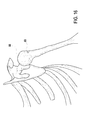
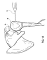
- FIGS. 15-21 illustrate steps of a method of replacing a portion of the humeral head with the partial humeral head prosthesis of the present invention
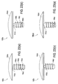
- FIGS. 22 and 23 illustrate various views of a partial humeral head prosthesis according to a second embodiment of the present invention
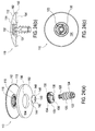
- FIG. 24 illustrate various views of a humeral head prosthesis according to a third embodiment
- FIG. 25 illustrates various views of a humeral head prosthesis reamer according to a third embodiment
- FIG. 26 illustrates various views of a reamer grasper instrument according to an exemplary embodiment
- FIG. 27 illustrates various views of an implant grasper instrument according to an exemplary embodiment
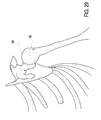
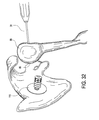
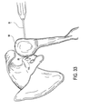
- FIGS. 28-34 illustrate steps of a method of replacing a portion of the humeral head with the humeral head prosthesis according to a third embodiment
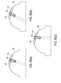
- FIG. 35 illustrates various views of a humeral head prosthesis seated on a humeral head.
- the invention provides prosthetic assembly for prosthetic and surgical methods for reconstitution of a joint, with special applications to the shoulder joint.
- the prosthetic assembly includes a partial humeral head prosthesis component that is configured to be inserted in a socket formed in the humerus.
- FIGS. 1-5 illustrate a first exemplary embodiment of partial humeral head prosthesis 10 of the present invention.
- Partial humeral head prosthesis 10 comprises a partial humeral head prosthesis cap 4 securely engaged to a partial implant or screw 2 by shoulder post 1.
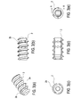
- FIGS. 3(a)-(e) illustrate additional views of the partial numeral head prosthesis implant or screw 2.
- FIGS. 4(a)-(c) illustrate additional views of the partial humeral head prosthesis cap 4.
- FIGS. 5(a)-(b) illustrate additional views of the shoulder post or pin 1.
- prosthesis cap 4 of the partial humeral head prosthesis 10 is configured to allow replacement of a portion of the humeral head with the prosthesis cap.
- partial humeral head prosthesis cap 4 has a convex configuration (a partial eclipse-type configuration), which is similar to the curvature of the humeral head to allow the prosthesis cap 4 to reconstruct the anatomy of the damaged humeral head.
- convex outer surface 4a ( FIGS. 4(a)-4(c) ) of the prosthesis cap 4 will permit both the full anatomical reconstruction of the humeral head and the introduction of the convex surface within the glenoid cavity.
- the concave, inner surface 4b ( FIG. 4(a) ) abuts the surface of the damaged articular bone to be replaced (i.e., portion of the humerus) and permits containment of any fractured, damaged humeral head.
- the dimension and measurements of the partial humeral head prosthesis cap 4 are a function of the patient's anatomy.
- the partial humeral head prosthesis implant or screw 2 shown in FIGS. 3(a)-(e) is engaged to the prosthesis cap 4 through shoulder post or pin 1 shown in FIGS.5(a)-(b) .
- implant or screw 2 is provided with threads 2a to allow the insertion and subsequent fixation of the screw (with prosthesis cap 4 attached thereto) into the humerus diaphyseal channel.
- a plurality of fenestrations or holes 2b formed through the body of the screw 2 permit the passage of any fixing material (such as acrylic cement, for example) through the walls of the screw 2, to increase the fixation of the device within the diaphyseal channel.
- Partial humeral head prosthesis 10 may be manufactured from titanium alloy or other metallic materials.
- the partial humeral head prosthesis cap 4 preferably is manufactured from materials similar to those of the screw 2 and pin 1.
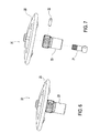
- FIGS. 6-8 illustrate various views of partial humeral head prosthesis duster 20 of the present invention.
- the partial humeral head prosthesis duster 20 comprises duster cap 25 securely engaging reamer 23 through ball post 21 and pin 22.
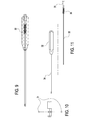
- FIGS. 9-11 illustrate a driver 30 for the partial humeral head prosthesis 10 of the present invention.
- Driver 30 comprises an inner rod 33 disposed within a cannulated rod 34, and a handle 32.
- Driver 30 also comprises a spring driver 36, a spring plug 35 and ball bearings 31.
- FIG. 12 illustrates a drill guide 40 for the partial humeral head prosthesis 10 of the present invention.
- Drill guide 40 comprises a handle frame 44, a guide arm 43, pins 41, 42 and spring latch 45.
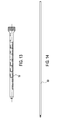
- FIG. 13 shows a drill sleeve 50 for use with the drill guide 40 of FIG. 12 in connection with the present invention.
- FIG. 14 illustrates a threaded pin 60 for attachment to, and retrograde drilling of, duster 20 in connection with the present invention, as described in the technique below.
- the present invention is used in arthroscopic surgery by fixating the humeral head prosthesis 10 of the present invention within a socket in the humerus.
- Preparation for an exemplary surgical technique relies upon radiographic film, surgical templates, and trial implants to determine and select the appropriate combination of end cap 4, screw 2 and pin 1 that make up partial humeral head prosthesis (implant) 10 to meet the patient's anatomical requirements.
- the remaining fractured/damaged humerus is resected using appropriate instrumentation designed specifically for the implant system.
- FIGS. 15-21 depict a method of replacing a portion of the humeral head with the partial humeral head prosthesis 10 of the present invention
- FIGS. 22 and 23 illustrate front and perspective views, respectively, of additional embodiments of a partial humeral head prosthesis 100(a), 100(b) formed according to a second embodiment of the present invention.
- Partial humeral head prosthesis 100(a), 100(b) is similar to the partial humeral head prosthesis 10 described above, but differs in that humeral head prosthesis 100(a), 100(b) is formed as a unitary structure rather than as an assembled structure (i.e., a partial humeral head prosthesis cap is integral to a partial implant or screw and not assembled to it).
- Partial humeral head prosthesis 100(a), 100(b) comprises a partial humeral head prosthesis cap 104(a), 104(b) securely attached to, and integral with, a partial implant or screw 102(a), 102(b).
- prosthesis cap 104(a), 104(b) is configured to allow replacement of a portion of the humeral head with the prosthesis cap.
- partial humeral head prosthesis cap 104(a), 104(b) has a convex configuration (a partial eclipse-type configuration), which is similar to the curvature of the humeral head to allow the prosthesis cap to reconstruct the anatomy of the damaged humeral head.
- the convex outer surface of the prosthesis cap 104(a), 104(b) permits both the full anatomical reconstruction of the humeral head and the introduction of the convex surface within the glenoid cavity.
- the concave, inner surface abuts the surface of the damaged articular bone to be replaced (i.e., portion of the humerus) and permits containment of any fractured, damaged humeral head.
- the dimension and measurements of the partial humeral head prosthesis cap 104(a), 104(b) are a function of the patient's anatomy.
- Engagement element (neck portion) 101(a), 101(b) is provided between the partial humeral head prosthesis implant or screw 102(a), 102(b) and the prosthesis cap 104(a), 104(b).
- Implant or screw 102(a), 102(b) is provided with threads 108(a), 108(b) to allow the insertion and subsequent fixation of the screw (with prosthesis cap attached thereto) into the humerus diaphyseal channel.
- the length of the implant 102(a), 102(b) varies according to the length of the diaphyseal channel of the humerus.
- a plurality of fenestrations or holes 106(a), 106(b) are formed through the body of the screw 102(a), 102(b) to permit the passage of any fixing material (such as acrylic cement, for example) through the walls of the screw, to increase the fixation of the device within the diaphyseal channel.
- the number of the fenestrations or holes 106(a), 106(b) depends on the length of the implant 102(a), 102(b) and also on the length of the diaphyseal channel of the humerus.
- Partial humeral head prosthesis 100(a), 100(b) may be manufactured from titanium alloy or other metallic materials.
- the partial humeral head prosthesis cap 104(a), 104(b) preferably is manufactured from materials similar to those of the screw 102(a), 102(b).
- Methods of conducting arthroscopic surgery by fixating the humeral head prosthesis 100(a), 100(b) within a socket in the humerus may be conducted by steps similar to those described and illustrated above with reference to humeral head prosthesis 10 of the first embodiment (for the humeral repair illustrated in FIGS. 15-21 ). Selection of the appropriate size for the partial humeral head prosthesis (implant) 100(a), 100(b) is based on the patient's anatomical requirements. The specific steps proceed as detailed above and with reference to FIGS. 15-21 .
- FIGS. 24a, 24b and 24c illustrate different views of humeral head prosthesis 110 formed according to a third embodiment.
- Humeral head prosthesis 110 is similar to partial humeral head prosthesis 10 described above, but differs significantly in that humeral head prosthesis 110 may articulate.
- Humeral head prosthesis 110 includes cap 112, screw 120, socket 130, articulating part 140 and spacer 150 as illustrated in FIG. 24a .
- Cap 112 includes inner surface 113, convex outer surface 114, receptacle 116 and helical grooves 118.
- Screw 120 is cannulated in shape and includes fenestrations or holes 122, humerus threads 124 and attachment threads 126. Screw 120 is provided with threads 124 to allow the insertion and subsequent fixation of screw 120 (with prosthesis cap 112 attached thereto) into the humerus diaphyseal channel. A plurality of fenestrations or holes 112 formed through the body of screw 120 permit the passage of any fixing material (such as acrylic cement, for example) through the walls of screw 120, to increase the fixation of humeral head prosthesis 110 within the diaphyseal channel.
- any fixing material such as acrylic cement, for example
- Socket 130 is defined by outside surface 131 between proximal end 134 and distal end 136. Outside surface 131 is cylindrical in shape and has attachment threads 133 extending between proximal end 134 and distal end 136. Socket 130 includes inside surface 132 that has a frustoconical shape tapering from proximal end 134 to distal end 136. Socket 130 also has socket opening 138 having a circular cross section located at distal end 136. Opening 138 extends from distal end 136 to inside surface 132 and has a cylindrical shape.
- Articulating part 140 has a frustoconical shape that tapers from proximal end 144 to distal end 146.
- Part 140 includes bore 142 that extends partially through part 140 from distal end 146 toward proximal end 144 and has helical grooves 143 along the surface of bore 142.
- bore 142 extends through articulating part 140 from distal end 146 to proximal end 144.
- Spacer 150 is cylindrical in shape and includes outer spacer surface 152 and inner spacer surface 154.
- Inner spacer surface 154 has a concave shape.
- Spacer 150 further includes circular opening 156, centered in the middle of spacer 150.
- inner spacer surface 154 is flat or has a convex shape.
- humeral head prosthesis 110 is formed by playing articulating part 140 within socket 130 so that the outside surface of articulating part 140 contacts inside surface 132 of socket 130. Further, bore 142 aligns with socket opening 138 to allow access to bore 142 through socket opening 138. Socket 130 is attached to cap 112. Socket 130 is housed within receptacle 116 of cap 112 and attachment threads 133 of socket 130 align and mate with helical grooves 118 of cap 112 to secure socket 130 within receptacle 116. Spacer 150 is attached to cap 112, with outer spacer surface 152 contacting inner surface 113 of cap 112.
- spacer 150 is not part of humeral head prosthesis 150 and inner surface 113 abuts the surface of the damaged articular bone.
- inner surface 113 may be concave or convex.
- Bore 142 of articulating part 140 houses attachment threads 126 of screw 120. Attachment threads 126 mate with helical grooves 143 of bore 142 to secure screw 120 to articulating part 140. Screw 120 extends through spacer opening 156 and socket opening 138 and away from cap 112.
- prosthesis cap 112 is attached to the humeral bone without the use of screw 120.
- a through-bolt is used to attach prosthesis cap 112 to the humeral bone.
- the through-bolt extends from one side of the humeral bone, through the humerus diaphyseal channel and attaches to prosthesis cap 112.
- the through-bolt may have threads similar to screw 120 to mate with helical grooves 143 to secure the through-bolt to articulating part 140. In this manner, the through-bolt securely seats prosthesis cap 112 on the humeral head.
- Other methods known in the art for seating prosthesis cap 112 on humeral bone may be employed without deviating from the inventive concept described in the present application.
- humeral head prosthesis 110 allows articulation or movement of cap 112 with respect to screw 120.
- Cap 112 may freely articulate in any direction between 0° and 30° off centerline axis, wherein the centerline axis typically aligns with the perpendicular of screw 120. This movement is provided by articulating part 140 and socket 130.
- Articulating part 140 and socket 130 act as a ball and socket joint respectively, allowing articulating part 140 to move along inside surface 132 of socket 130. This articutation allows cap 112 to be self-centering and enhances the seating of cap 112 on the humeral bone.
- the convex configuration (a partial eclipse-type configuration) of humeral head prosthesis cap 112 is similar to the curvature of the humeral head to allow prosthesis cap 112 to reconstruct the anatomy of the damaged humeral head.
- Convex outer surface 114 of prosthesis cap 112 permits both the full anatomical reconstruction of the humeral head and the introduction of convex surface 114 within the glenoid cavity.
- Concave inner surface 154 of spacer 150 abuts the surface of the damaged articular bone to be replaced (i.e., portion of the humerus) and permits containment of any fractured, damaged numeral head.
- the dimension and measurements of humeral head prosthesis cap 112 is a function of the patient's anatomy.
- prosthesis cap 112 may be used as a complete prosthesis or as a partial prosthesis to treat focal defects in the humeral bone.
- Prosthesis cap 112 may also be used to treat osteoarthritis in the humeral bone as well as other medical conditions.
- the uses of prosthesis cap 112 should not be limited to the above mentioned conditions, but may have a variety of different uses. Further, prosthesis cap 112 may also be used to treat medical conditions in other bones besides the humeral bone.
- Humeral head prosthesis cap 112 may be manufactured from titanium alloy or other metallic materials. Humeral head prosthesis cap 112 is preferably manufactured from materials similar to those of screw 120.
- FIGS. 25a, 25b and 25c illustrate different views of reamer assembly 200 formed according to a third embodiment.
- Reamer assembly 200 is similar to partial humeral head prosthesis duster 20 described above, but differs in many respects, one being that reamer assembly 200 may articulate.
- Reamer assembly 200 includes reamer 210, drive pivot 220 and retaining cap 230 as illustrated in FIG. 25a .
- Reamer 210 has a circular cross section, similar to humerus head prosthesis 110.
- Reamer 210 includes three cutting edges 216, 217 and 218 that are equally spaced at 120° intervals around reamer 210. Cutting edges 216, 217 and 218 extended from the outside surface of reamer 210 toward middle of reamer 210. In another embodiment, cutting edges 216, 217 and 218 are not equally spaced around reamer 210.
- Reamer 210 further includes cylindrical socket 214.
- Socket 214 includes frustoconical shaped indentation 215 centered in the middle of socket 214 and extending away from reamer face 211.
- Reamer 210 further includes slots 212 and 213 that are equally spaced along the outside wall of socket 214. Slots 212 and 213 create openings between the outside wall of socket 214 and indentation 215. Further, slots 212 and 213 are "U" shaped, extending away from reamer face 211 with an opening toward reamer face 211. Slots 212 and 213 do not extend the total depth of socket 214.
- Drive pivot 220 has a frustoconical shape, tapering from proximal end 228 to distal end 226. Further, drive pivot 220 includes bore 228 that has a cylindrical shape. Bore 228 extends from proximal end 228 toward distal end 226 but does not extend completely too distal end 226. Bore 226 also has helical grooves 229 along its surface. Drive pivot 220 includes cylindrical arms 222 and 224 that extend perpendicularly away from drive pivot 220. Retaining cap 230 is circular and includes opening 232 at the center of retaining cap 230.
- reamer assembly 200 is formed by placing drive pivot 220 within indentation 215 of socket 214. Arms 222 and 224 of drive pivot 220 extended through slots 212 and 213 of socket 214. Retaining cap 230 covers socket 214 and drive pivot 220, with opening 232 of retaining cap 230 aligned with bore 228 of drive pivot 220. Threaded pin 60 extends through retaining cap 230 and mate with helical grooves 229 of bare 228.
- bore 228 does not have helical grooves 229, but contains a pin extending from one side of bore 228 to another.
- Threaded pin 60 incudes a slot at one end that engages with reamer assembly 200.
- threaded pin 60 extends through retaining cap 230 and the end of threaded pin 60 that contains the slot enters bore 228.
- the pin within bore 228 is sized to allow it to rest within the slot of threaded pin 60. In this manner, threaded pin 60 may engage and exert a torque on reamer assembly 200.
- threaded pin 60 is rotated and exerts a torque on drive pivot 220.
- Arms 222 and 224 of drive pivot 220 subsequently exert a force on the sides of slots 218 and 219, causing reamer assembly 200 to rotate.
- reamer 200 may be drilled in a retrograde manner.
- reamer driver 210 may articulate in any direction from 0° to 30° off centerline axis. Typically, the centerline axis aligns with the perpendicular of threaded pin 60.
- socket 214 includes a bore that extends away from reamer face 211.
- the bore extends from the bottom of indentation 215 to the side of socket 214 opposite reamer face 211.
- threaded pin 60 pass through the bore and mates with helical grooves 229 of drive pin 220. Accordingly, reamer 200 may be drilled in a forward antegrade manner.
- FIGS. 26a, 26b and 26c illustrate reamer grasper 300.
- FIG. 26a shows reamer grasper 300 that includes grasper tip 310, tube 320, actuator 330, washer 332, wishbone spring 334, handles pins 336 and 338, wishbone thumb 340, wishbone finger 342, wishbone lock 358 and wishbone lock pins 352, 354, and 356.
- FIG. 26b shows grasper tip 310, grasper tip 310 includes tube 312, cutter pin 314, tip pin 316 and grasper jaw 318.
- Reamer gasper 300 is used in surgery to grasp reamer assembly 200.
- FIGS. 27a, 27b and 27c illustrate implant grasper 400.
- FIG. 26a shows implant grasper 400 that includes grasper tip 410, tube 420, actuator 430, washer 432, wishbone spring 434, handles pins 436 and 438, wishbone thumb 440, wishbone finger 442, wishbone lock 458 and wishbone lock pins 452, 454, and 456.
- FIG. 27b shows grasper tip 410
- grasper tip 410 includes tube 412, cutter pin 414, tip pin 416 and grasper jaw 418.
- Implant grasper 400 is used in surgery to grasp humeral head prosthesis 110.
- a method of conducting arthroscopic surgery by fixating humeral head prosthesis 110 of the present embodiment within a socket in the humerus is now described.
- Preparation for an exemplary surgical technique relies upon radiographic film, surgical templates, and trial implants to determine and select the appropriate combination of prosthesis cap 112 and screw 120 that make up humeral head prosthesis 110 to meet the patient's anatomical requirements.
- the remaining fractured/damaged humerus is resected using appropriate instrumentation designed specifically for the implant system.
- FIGS. 28-34 depict a method of replacing a portion of the humeral head with humeral head prosthesis 110:
- FIG. 28 shows guide 40 (for example, a C-Ring guide) inserted through the anterior incision and rotator interval.
- the C-Ring guide cup is placed over the chondral defect so that it covers the entire defect and sits flush on the articular surface.
- C-Ring guide drill sleeve 50 is pushed against the skin of the lateral shoulder. At that location, a skin incision is made and the soft tissue is bluntly dissected down to bone taking care to avoid the axillary nerve.
- C-Ring guide drill sleeve 50 is further inserted into the wound, until it makes contact with bone. Care must be taken to avoid the axillary nerve when inserting drill sleeve 50.
- a guide pin (such as a 2.4mm guide pin) is inserted into drill sleeve 50 and the pin is drilled through humerus head 88 until it exits the humeral articular surface.
- the pin is detached from the drill and left in place.
- the C-Ring guide 40 is now removed completely or left in place to act as a drill stop.
- a soft tissue protector is placed over the 2.4mm guide pin.
- a 4mm cannulated drill is placed over the 2.4mm guide pin and through the soft tissue protector. It is then drilled through the lateral humerus until it exits the articular surface.
- FIG. 29 shows tunnel or hole 80 through humerus head 88 made by the 4mm cannulated drill.
- the 4mm cannulated drill, C-Ring guide 40, and the soft tissue protector are removed and the 2.4mm guide pin is left in place.
- a transhumeral tunnel sleeve is placed over the guide pin and through the previously drilled 4mm tunnel 80 until it is flush with the articular surface. The guide pin is now removed.
- reamer grasper 300 is connected to reamer grasper 300 and inserted through the anterior shoulder incision and rotator interval. Threaded pin 60 is attached to a handled chuck and inserted through the transhumeral tunnel sleeve and into the intraarticular space.
- reamer grasper 300 is used to manipulate reamer 200 into place and mate it with threaded pin 60. Once connection of reamer 200 and threaded pin 60 is confirmed, the handled chuck is removed and threaded pin 60 is connected to power. Reamer grasper 300 is disengaged and the articular surface is reamed until the reamer depth stop ring ful ly contacts humeral head 88 to create reamed articular region 95. The power drill is now disconnected. Reamer grasper 300 and handled chuck are used to disengage reamer 200 from threaded pin 60 and both items are removed from the intraarticular space.
- implant grasper 400 is used to insert the appropriate size humeral head prosthesis 110 through the anterior shoulder incision and rotator interval.
- Implant driver 30 is inserted through the transhumeral tunnel sleeve and connected to humeral head prosthesis 110 within the intraarticular space.
- Humeral head prosthesis 110 is driven into reamed articular region 95 in a retrograde fashion using implant driver 30.
- implant 30 driver is disengaged and removed.
- the transhumeral tunnel sleeve is removed.
- FIGS. 35a, 35b and 35c illustrate humeral head prosthesis 110 seated on humeral head 88 after completion of the above described method.
- FIG. 35a illustrates humeral head prosthesis 110 in a neutral non-articulated position.
- Prosthesis cap 112 is perpendicular to screw 120 and no articulation is necessary for prosthesis cap 112 to seat correctly on humeral head 88 since the initial drilling pin exited the surface of the bone at exactly a perpendicular angle.
- FIGS. 35b and 35c illustrates humeral head prosthesis 110 in an off axis articulated position.
- Prosthesis cap 112 is articulated or tilted with regard to the perpendicular of screw 130. This articulation allows prosthesis cap 112 to be correctly seated on humeral head 88. If prosthesis cap 112 could not articulate, prosthesis cap 112 might not be correctly seated on humeral head 88, leaving a gap between humeral head 88 and prosthesis cap 112.
- humeral head prosthesis 110 and reamer assembly 200 allow for slight errors in the placement of the initial drilling pin during the method described above. If the initial drilling pin does not exit the surface of humeral head 88 at exactly a perpendicular angle, prosthesis 110 and reamer 200 may articulate to compensate for the drilling error, allowing for complete seating of prosthesis 110 on humeral head 88.
Landscapes
- Health & Medical Sciences (AREA)
- Life Sciences & Earth Sciences (AREA)
- Orthopedic Medicine & Surgery (AREA)
- Animal Behavior & Ethology (AREA)
- Veterinary Medicine (AREA)
- Oral & Maxillofacial Surgery (AREA)
- Public Health (AREA)
- Engineering & Computer Science (AREA)
- Biomedical Technology (AREA)
- Heart & Thoracic Surgery (AREA)
- General Health & Medical Sciences (AREA)
- Surgery (AREA)
- Transplantation (AREA)
- Cardiology (AREA)
- Vascular Medicine (AREA)
- Molecular Biology (AREA)
- Medical Informatics (AREA)
- Nuclear Medicine, Radiotherapy & Molecular Imaging (AREA)
- Dentistry (AREA)
- Physical Education & Sports Medicine (AREA)
- Prostheses (AREA)
Abstract
Description
- The present invention relates to surgical reconstitution of anatomical structures and, in particular, to prosthetic replacement of such structures.
- Instability and other maladies of human joints, such as arthrosis or fracture, can be sufficiently acute that prosthetic replacement of compromised joint features may be indicated. For example, in shoulder reconstruction, the humeral head may be replaced by first resecting the humeral head from the humerus and then installing a humeral prosthetic at the resection.
- Various prostheses have been designed to mimic the portion of the joint or joint region being replaced. A shoulder prostheses, for example, includes a stem to be anchored in the humeral canal and a hemispherical head to be positioned within the glenoid cavity of the scapula. The more-recently devised modular shoulder prostheses generally are modular systems that allow flexibility with respect to either the tilt angle or the radial offset between the head and stem.
- The present invention provides a novel prosthetic assembly for prosthetic and surgical methods for reconstitution of a joint, with special applications to the shoulder joint. The prosthetic assembly includes a partial humeral head component.
- The present invention also includes a humeral head cap used in conjunction with a humeral head reamer (preferably a retrograde reamer) that resurfaces an articular surface in a retrograde manner without direct exposure to the surface. In this manner, slight errors in placement of the initial drill pin are corrected by the articulation of the reamer and the humeral head cap.
- The present invention also includes a prosthetic for replacing a portion of a bone that includes a spherical head and a post having a proximal end and a distal end. The spherical head has a convex surface suitable to be introduced within a joint cavity, a concave surface that contacts the bone and an articulating coupling element for attaching the proximal end of the post to the spherical head. The spherical head is contoured to engage a complementary articular surface.
- The post is a cannulated member at least partially insertable within a diaphyseal channel of the bone and is removably attached to the spherical head. The coupling element of the prosthetic includes a socket and an articulating part that interacts with the socket to form an articulating ball and socket joint, so that the spherical head can articulate in all directions in relationship to the post.
- The present invention also includes a numeral prosthetic component, that includes a cannulated screw having a proximal end and a distal end, where at least a portion of the distal end is configured to be at least partially insertable within the humeral diaphyseal channel. The component includes a head having a convex surface suitable to be introduced within a joint cavity and an articulating part.
- The articulating part of the component is configured to attach the cannulated screw to the head to form an articulated joint, wherein the articulating joint allows the head to articulate in relationship to the screw.
- The present invention also includes a surgical component that has a spherical body suitable to be introduced within a joint cavity. The body also has at least one cutting edge and an articulating coupling element for attaching the body to a driver. The body of the component may include three cutting edges and the articulating coupling element allows the body to articulate in relationship to an attached driver.
- These and other features and advantages of the invention will be more apparent from the following detailed description that is provided in connection with the accompanying drawings and illustrated exemplary embodiments of the invention.
-
FIGS. 1-5 illustrate various views of a partial humeral head prosthesis according to a first embodiment of the present invention; -
FIGS. 6-8 illustrate various views of a partial humeral head prosthesis duster of the present invention; -
FIGS. 9-11 illustrate various views of a driver for the partial humeral head prosthesis of the present invention; -
FIG. 12 illustrates a drill guide for installing the partial humeral head prosthesis of the present invention; -
FIG. 13 illustrates a drill sleeve for use with the drill guide of the present invention; -
FIG. 14 illustrates various views of a pin for retrograde drilling of the duster ofFIGS. 6-8 in connection with the present invention; -
FIGS. 15-21 illustrate steps of a method of replacing a portion of the humeral head with the partial humeral head prosthesis of the present invention; -
FIGS. 22 and 23 illustrate various views of a partial humeral head prosthesis according to a second embodiment of the present invention; -
FIG. 24 illustrate various views of a humeral head prosthesis according to a third embodiment; -
FIG. 25 illustrates various views of a humeral head prosthesis reamer according to a third embodiment; -
FIG. 26 illustrates various views of a reamer grasper instrument according to an exemplary embodiment; -
FIG. 27 illustrates various views of an implant grasper instrument according to an exemplary embodiment; -
FIGS. 28-34 illustrate steps of a method of replacing a portion of the humeral head with the humeral head prosthesis according to a third embodiment; and -
FIG. 35 illustrates various views of a humeral head prosthesis seated on a humeral head. - The invention provides prosthetic assembly for prosthetic and surgical methods for reconstitution of a joint, with special applications to the shoulder joint. As detailed below, the prosthetic assembly includes a partial humeral head prosthesis component that is configured to be inserted in a socket formed in the humerus.
- Referring now to the drawings, where like elements are designated by like reference numerals.
FIGS. 1-5 illustrate a first exemplary embodiment of partialhumeral head prosthesis 10 of the present invention. Partialhumeral head prosthesis 10 comprises a partial humeral head prosthesis cap 4 securely engaged to a partial implant orscrew 2 by shoulder post 1.FIGS. 3(a)-(e) illustrate additional views of the partial numeral head prosthesis implant orscrew 2.FIGS. 4(a)-(c) illustrate additional views of the partial humeral head prosthesis cap 4.FIGS. 5(a)-(b) illustrate additional views of the shoulder post or pin 1. - As shown in the drawings, prosthesis cap 4 of the partial
humeral head prosthesis 10 is configured to allow replacement of a portion of the humeral head with the prosthesis cap. In an exemplary embodiment, and as shown inFIGS. 4(a)-(c) , partial humeral head prosthesis cap 4 has a convex configuration (a partial eclipse-type configuration), which is similar to the curvature of the humeral head to allow the prosthesis cap 4 to reconstruct the anatomy of the damaged humeral head. As described below, convexouter surface 4a (FIGS. 4(a)-4(c) ) of the prosthesis cap 4 will permit both the full anatomical reconstruction of the humeral head and the introduction of the convex surface within the glenoid cavity. The concave,inner surface 4b (FIG. 4(a) ) abuts the surface of the damaged articular bone to be replaced (i.e., portion of the humerus) and permits containment of any fractured, damaged humeral head. The dimension and measurements of the partial humeral head prosthesis cap 4 are a function of the patient's anatomy. - The partial humeral head prosthesis implant or
screw 2 shown inFIGS. 3(a)-(e) is engaged to the prosthesis cap 4 through shoulder post or pin 1 shown inFIGS.5(a)-(b) . As detailed inFIGS. 3(a)-(e) , implant orscrew 2 is provided withthreads 2a to allow the insertion and subsequent fixation of the screw (with prosthesis cap 4 attached thereto) into the humerus diaphyseal channel. A plurality of fenestrations orholes 2b formed through the body of thescrew 2 permit the passage of any fixing material (such as acrylic cement, for example) through the walls of thescrew 2, to increase the fixation of the device within the diaphyseal channel. - Partial
humeral head prosthesis 10 may be manufactured from titanium alloy or other metallic materials. The partial humeral head prosthesis cap 4 preferably is manufactured from materials similar to those of thescrew 2 and pin 1. -
FIGS. 6-8 illustrate various views of partial humeralhead prosthesis duster 20 of the present invention. As shown in the drawings, the partial humeralhead prosthesis duster 20 comprisesduster cap 25 securely engagingreamer 23 throughball post 21 andpin 22. -
FIGS. 9-11 illustrate adriver 30 for the partialhumeral head prosthesis 10 of the present invention.Driver 30 comprises aninner rod 33 disposed within acannulated rod 34, and ahandle 32.Driver 30 also comprises aspring driver 36, a spring plug 35 andball bearings 31. -
FIG. 12 illustrates adrill guide 40 for the partialhumeral head prosthesis 10 of the present invention.Drill guide 40 comprises ahandle frame 44, aguide arm 43, pins 41, 42 andspring latch 45. -
FIG. 13 shows adrill sleeve 50 for use with thedrill guide 40 ofFIG. 12 in connection with the present invention.FIG. 14 illustrates a threadedpin 60 for attachment to, and retrograde drilling of,duster 20 in connection with the present invention, as described in the technique below. - The present invention is used in arthroscopic surgery by fixating the humeral head prosthesis 10 of the present invention within a socket in the humerus. Preparation for an exemplary surgical technique relies upon radiographic film, surgical templates, and trial implants to determine and select the appropriate combination of end cap 4,
screw 2 and pin 1 that make up partial humeral head prosthesis (implant) 10 to meet the patient's anatomical requirements. The remaining fractured/damaged humerus is resected using appropriate instrumentation designed specifically for the implant system. - Specific steps of an exemplary method of humeral repair using the prosthesis of the present invention are detailed below and with reference to
FIGS. 15-21 (which depict a method of replacing a portion of the humeral head with the partial humeral head prosthesis 10 of the present invention): - Use drill guide 40 with orthogonal orientation features to place 2.4 mm drill pin thru
humeral head 88, exiting at center of focal defect (FIG. 15 ). - Remove
drill guide 40, leaving the 2.4 mm drill pin in place. - Over-drill with 4 mm cannulated drill over 2.4 mm drill pin to form tunnel or hole 80 (
FIG. 16 ) through thehumerus 88, remove 4 mm drill leaving 2.4 mm drill pin in place. -
Place sleeve component 50 over 2.4 mm drill pin, verifying whethersleeve 50 is in view with arthroscope. Remove 2.4 mm drill pin. - Insert threaded
pin component 60 upsleeve 50 into view of arthroscope. Bring duster component 20 (FIG. 17 ), loaded onto insertion hand instrument, through rotator cuff interval portal into view. Assembleduster 20 to threadedpin 60 by hand. - Load power drill onto threaded
pin 60 and apply retrograde force while running drill to create a counterbore socket at focal defect location (FIG. 18 ). - Remove power drill. Grasp
duster component 20 with insertion hand instrument and remove threadedpin 60, then removeduster component 20.Sleeve 50 should still be in place. - Insert
implant inserter component 10 up sleeve into view of arthroscope. Bringimplant 10, loaded onto insertion hand instrument, thru the rotator cuff interval portal into view (FIG. 19 ). Assembleimplant 10 on inserter by hand. -
Retrograde insert implant 10 into the prepared socket until cap 4 ofimplant 10 is flush with the surrounding articular surface of the humerus (FIG. 20 ). - Remove the inserter, remove
sleeve 50 and confirm thatimplant 10 is correctly installed (FIG. 21 ). -
FIGS. 22 and 23 illustrate front and perspective views, respectively, of additional embodiments of a partial humeral head prosthesis 100(a), 100(b) formed according to a second embodiment of the present invention. Partial humeral head prosthesis 100(a), 100(b) is similar to the partialhumeral head prosthesis 10 described above, but differs in that humeral head prosthesis 100(a), 100(b) is formed as a unitary structure rather than as an assembled structure (i.e., a partial humeral head prosthesis cap is integral to a partial implant or screw and not assembled to it). Partial humeral head prosthesis 100(a), 100(b) comprises a partial humeral head prosthesis cap 104(a), 104(b) securely attached to, and integral with, a partial implant or screw 102(a), 102(b). - As shown in
FIGS. 22 and 23 , prosthesis cap 104(a), 104(b) is configured to allow replacement of a portion of the humeral head with the prosthesis cap. As in the previously-described embodiment, partial humeral head prosthesis cap 104(a), 104(b) has a convex configuration (a partial eclipse-type configuration), which is similar to the curvature of the humeral head to allow the prosthesis cap to reconstruct the anatomy of the damaged humeral head. The convex outer surface of the prosthesis cap 104(a), 104(b) permits both the full anatomical reconstruction of the humeral head and the introduction of the convex surface within the glenoid cavity. The concave, inner surface abuts the surface of the damaged articular bone to be replaced (i.e., portion of the humerus) and permits containment of any fractured, damaged humeral head. The dimension and measurements of the partial humeral head prosthesis cap 104(a), 104(b) are a function of the patient's anatomy. - Engagement element (neck portion) 101(a), 101(b) is provided between the partial humeral head prosthesis implant or screw 102(a), 102(b) and the prosthesis cap 104(a), 104(b). Implant or screw 102(a), 102(b) is provided with threads 108(a), 108(b) to allow the insertion and subsequent fixation of the screw (with prosthesis cap attached thereto) into the humerus diaphyseal channel. As shown in
FIGS. 22 and 23 , the length of the implant 102(a), 102(b) varies according to the length of the diaphyseal channel of the humerus. - A plurality of fenestrations or holes 106(a), 106(b) are formed through the body of the screw 102(a), 102(b) to permit the passage of any fixing material (such as acrylic cement, for example) through the walls of the screw, to increase the fixation of the device within the diaphyseal channel. The number of the fenestrations or holes 106(a), 106(b) depends on the length of the implant 102(a), 102(b) and also on the length of the diaphyseal channel of the humerus.
- Partial humeral head prosthesis 100(a), 100(b) may be manufactured from titanium alloy or other metallic materials. The partial humeral head prosthesis cap 104(a), 104(b) preferably is manufactured from materials similar to those of the screw 102(a), 102(b).
- Methods of conducting arthroscopic surgery by fixating the humeral head prosthesis 100(a), 100(b) within a socket in the humerus may be conducted by steps similar to those described and illustrated above with reference to humeral head prosthesis 10 of the first embodiment (for the humeral repair illustrated in
FIGS. 15-21 ). Selection of the appropriate size for the partial humeral head prosthesis (implant) 100(a), 100(b) is based on the patient's anatomical requirements. The specific steps proceed as detailed above and with reference toFIGS. 15-21 . -
FIGS. 24a, 24b and 24c illustrate different views ofhumeral head prosthesis 110 formed according to a third embodiment. -
Humeral head prosthesis 110 is similar to partialhumeral head prosthesis 10 described above, but differs significantly in thathumeral head prosthesis 110 may articulate. -
Humeral head prosthesis 110 includescap 112,screw 120,socket 130, articulatingpart 140 andspacer 150 as illustrated inFIG. 24a .Cap 112 includesinner surface 113, convexouter surface 114,receptacle 116 andhelical grooves 118. -
Screw 120 is cannulated in shape and includes fenestrations or holes 122,humerus threads 124 andattachment threads 126.Screw 120 is provided withthreads 124 to allow the insertion and subsequent fixation of screw 120 (withprosthesis cap 112 attached thereto) into the humerus diaphyseal channel. A plurality of fenestrations or holes 112 formed through the body ofscrew 120 permit the passage of any fixing material (such as acrylic cement, for example) through the walls ofscrew 120, to increase the fixation ofhumeral head prosthesis 110 within the diaphyseal channel. -
Socket 130 is defined byoutside surface 131 betweenproximal end 134 anddistal end 136. Outsidesurface 131 is cylindrical in shape and hasattachment threads 133 extending betweenproximal end 134 anddistal end 136.Socket 130 includes insidesurface 132 that has a frustoconical shape tapering fromproximal end 134 todistal end 136.Socket 130 also hassocket opening 138 having a circular cross section located atdistal end 136.Opening 138 extends fromdistal end 136 toinside surface 132 and has a cylindrical shape. - Articulating
part 140 has a frustoconical shape that tapers fromproximal end 144 todistal end 146.Part 140 includes bore 142 that extends partially throughpart 140 fromdistal end 146 towardproximal end 144 and hashelical grooves 143 along the surface ofbore 142. In another embodiment, bore 142 extends through articulatingpart 140 fromdistal end 146 toproximal end 144. -
Spacer 150 is cylindrical in shape and includesouter spacer surface 152 andinner spacer surface 154.Inner spacer surface 154 has a concave shape.Spacer 150 further includescircular opening 156, centered in the middle ofspacer 150. In another embodiment,inner spacer surface 154 is flat or has a convex shape. - As shown in
FIGS. 24b and 24c ,humeral head prosthesis 110 is formed by playing articulatingpart 140 withinsocket 130 so that the outside surface of articulatingpart 140 contacts insidesurface 132 ofsocket 130. Further, bore 142 aligns withsocket opening 138 to allow access to bore 142 throughsocket opening 138.Socket 130 is attached to cap 112.Socket 130 is housed withinreceptacle 116 ofcap 112 andattachment threads 133 ofsocket 130 align and mate withhelical grooves 118 ofcap 112 to securesocket 130 withinreceptacle 116.Spacer 150 is attached to cap 112, withouter spacer surface 152 contactinginner surface 113 ofcap 112. - In another embodiment,
spacer 150 is not part ofhumeral head prosthesis 150 andinner surface 113 abuts the surface of the damaged articular bone. In this embodiment,inner surface 113 may be concave or convex. - Bore 142 of articulating
part 140houses attachment threads 126 ofscrew 120.Attachment threads 126 mate withhelical grooves 143 ofbore 142 to securescrew 120 to articulatingpart 140.Screw 120 extends throughspacer opening 156 andsocket opening 138 and away fromcap 112. - In another embodiment,
prosthesis cap 112 is attached to the humeral bone without the use ofscrew 120. In this embodiment a through-bolt is used to attachprosthesis cap 112 to the humeral bone. The through-bolt extends from one side of the humeral bone, through the humerus diaphyseal channel and attaches toprosthesis cap 112. The through-bolt may have threads similar to screw 120 to mate withhelical grooves 143 to secure the through-bolt to articulatingpart 140. In this manner, the through-bolt securely seatsprosthesis cap 112 on the humeral head. Other methods known in the art forseating prosthesis cap 112 on humeral bone may be employed without deviating from the inventive concept described in the present application. - The above described configuration of
humeral head prosthesis 110 allows articulation or movement ofcap 112 with respect to screw 120.Cap 112 may freely articulate in any direction between 0° and 30° off centerline axis, wherein the centerline axis typically aligns with the perpendicular ofscrew 120. This movement is provided by articulatingpart 140 andsocket 130. Articulatingpart 140 andsocket 130 act as a ball and socket joint respectively, allowing articulatingpart 140 to move along insidesurface 132 ofsocket 130. This articutation allowscap 112 to be self-centering and enhances the seating ofcap 112 on the humeral bone. - As in previously-described embodiments, the convex configuration (a partial eclipse-type configuration) of humeral
head prosthesis cap 112 is similar to the curvature of the humeral head to allowprosthesis cap 112 to reconstruct the anatomy of the damaged humeral head. Convexouter surface 114 ofprosthesis cap 112 permits both the full anatomical reconstruction of the humeral head and the introduction ofconvex surface 114 within the glenoid cavity. Concaveinner surface 154 ofspacer 150 abuts the surface of the damaged articular bone to be replaced (i.e., portion of the humerus) and permits containment of any fractured, damaged numeral head. The dimension and measurements of humeralhead prosthesis cap 112 is a function of the patient's anatomy. - As described in this embodiment,
prosthesis cap 112 may be used as a complete prosthesis or as a partial prosthesis to treat focal defects in the humeral bone.Prosthesis cap 112 may also be used to treat osteoarthritis in the humeral bone as well as other medical conditions. The uses ofprosthesis cap 112 should not be limited to the above mentioned conditions, but may have a variety of different uses. Further,prosthesis cap 112 may also be used to treat medical conditions in other bones besides the humeral bone. - Humeral
head prosthesis cap 112 may be manufactured from titanium alloy or other metallic materials. Humeralhead prosthesis cap 112 is preferably manufactured from materials similar to those ofscrew 120. -
FIGS. 25a, 25b and 25c illustrate different views ofreamer assembly 200 formed according to a third embodiment. -
Reamer assembly 200 is similar to partial humeralhead prosthesis duster 20 described above, but differs in many respects, one being thatreamer assembly 200 may articulate. -
Reamer assembly 200 includesreamer 210,drive pivot 220 and retainingcap 230 as illustrated inFIG. 25a .Reamer 210 has a circular cross section, similar tohumerus head prosthesis 110.Reamer 210 includes three cuttingedges reamer 210. Cuttingedges reamer 210 toward middle ofreamer 210. In another embodiment, cuttingedges reamer 210. -
Reamer 210 further includescylindrical socket 214.Socket 214 includes frustoconical shapedindentation 215 centered in the middle ofsocket 214 and extending away fromreamer face 211.Reamer 210 further includesslots socket 214.Slots socket 214 andindentation 215. Further,slots reamer face 211 with an opening towardreamer face 211.Slots socket 214. -
Drive pivot 220 has a frustoconical shape, tapering fromproximal end 228 todistal end 226. Further,drive pivot 220 includes bore 228 that has a cylindrical shape.Bore 228 extends fromproximal end 228 towarddistal end 226 but does not extend completely toodistal end 226. Bore 226 also hashelical grooves 229 along its surface.Drive pivot 220 includescylindrical arms drive pivot 220. Retainingcap 230 is circular and includesopening 232 at the center of retainingcap 230. - As illustrated in
FIG. 25b and 25c ,reamer assembly 200 is formed by placingdrive pivot 220 withinindentation 215 ofsocket 214.Arms drive pivot 220 extended throughslots socket 214. Retainingcap 230 coverssocket 214 and drivepivot 220, with opening 232 of retainingcap 230 aligned withbore 228 ofdrive pivot 220. Threadedpin 60 extends through retainingcap 230 and mate withhelical grooves 229 of bare 228. - In another embodiment, bore 228 does not have
helical grooves 229, but contains a pin extending from one side ofbore 228 to another. Threadedpin 60 incudes a slot at one end that engages withreamer assembly 200. In use, threadedpin 60 extends through retainingcap 230 and the end of threadedpin 60 that contains the slot enters bore 228. The pin withinbore 228 is sized to allow it to rest within the slot of threadedpin 60. In this manner, threadedpin 60 may engage and exert a torque onreamer assembly 200. - In operation, threaded
pin 60 is rotated and exerts a torque ondrive pivot 220.Arms drive pivot 220 subsequently exert a force on the sides ofslots 218 and 219, causingreamer assembly 200 to rotate. In this embodiment,reamer 200 may be drilled in a retrograde manner. - With
arms slots pivot 220 located withinindentation 215,reamer driver 210 may articulate in any direction from 0° to 30° off centerline axis. Typically, the centerline axis aligns with the perpendicular of threadedpin 60. - In another embodiment,
socket 214 includes a bore that extends away fromreamer face 211. The bore extends from the bottom ofindentation 215 to the side ofsocket 214opposite reamer face 211. In this embodiment, threadedpin 60 pass through the bore and mates withhelical grooves 229 ofdrive pin 220. Accordingly,reamer 200 may be drilled in a forward antegrade manner. -
FIGS. 26a, 26b and 26c illustratereamer grasper 300.FIG. 26a showsreamer grasper 300 that includesgrasper tip 310,tube 320,actuator 330,washer 332,wishbone spring 334, handles pins 336 and 338,wishbone thumb 340,wishbone finger 342,wishbone lock 358 and wishbone lock pins 352, 354, and 356. -
FIG. 26b showsgrasper tip 310,grasper tip 310 includestube 312,cutter pin 314,tip pin 316 andgrasper jaw 318.Reamer gasper 300 is used in surgery to graspreamer assembly 200. -
FIGS. 27a, 27b and 27c illustrateimplant grasper 400.FIG. 26a showsimplant grasper 400 that includesgrasper tip 410,tube 420,actuator 430,washer 432,wishbone spring 434, handles pins 436 and 438,wishbone thumb 440,wishbone finger 442,wishbone lock 458 and wishbone lock pins 452, 454, and 456. -
FIG. 27b showsgrasper tip 410,grasper tip 410 includestube 412,cutter pin 414,tip pin 416 andgrasper jaw 418.Implant grasper 400 is used in surgery to grasphumeral head prosthesis 110. - A method of conducting arthroscopic surgery by fixating
humeral head prosthesis 110 of the present embodiment within a socket in the humerus is now described. Preparation for an exemplary surgical technique relies upon radiographic film, surgical templates, and trial implants to determine and select the appropriate combination ofprosthesis cap 112 and screw 120 that make uphumeral head prosthesis 110 to meet the patient's anatomical requirements. The remaining fractured/damaged humerus is resected using appropriate instrumentation designed specifically for the implant system. - Specific steps of a method of humeral repair are detailed below with reference to
FIGS. 28-34 (which depict a method of replacing a portion of the humeral head with humeral head prosthesis 110): - Step 1
- After the focal chondral defect is identified on the humeral articular surface, a small anterior incision is made.
FIG. 28 shows guide 40 (for example, a C-Ring guide) inserted through the anterior incision and rotator interval. The C-Ring guide cup is placed over the chondral defect so that it covers the entire defect and sits flush on the articular surface. C-Ringguide drill sleeve 50 is pushed against the skin of the lateral shoulder. At that location, a skin incision is made and the soft tissue is bluntly dissected down to bone taking care to avoid the axillary nerve. C-Ringguide drill sleeve 50 is further inserted into the wound, until it makes contact with bone. Care must be taken to avoid the axillary nerve when insertingdrill sleeve 50. -
Step 2 - A guide pin (such as a 2.4mm guide pin) is inserted into
drill sleeve 50 and the pin is drilled throughhumerus head 88 until it exits the humeral articular surface. The pin is detached from the drill and left in place. The C-Ring guide 40 is now removed completely or left in place to act as a drill stop. Next, a soft tissue protector is placed over the 2.4mm guide pin. A 4mm cannulated drill is placed over the 2.4mm guide pin and through the soft tissue protector. It is then drilled through the lateral humerus until it exits the articular surface.FIG. 29 shows tunnel orhole 80 throughhumerus head 88 made by the 4mm cannulated drill. The 4mm cannulated drill, C-Ring guide 40, and the soft tissue protector are removed and the 2.4mm guide pin is left in place. A transhumeral tunnel sleeve is placed over the guide pin and through the previously drilled4mm tunnel 80 until it is flush with the articular surface. The guide pin is now removed. - Step 3
- In
FIG. 30 , theappropriate size reamer 200 is connected toreamer grasper 300 and inserted through the anterior shoulder incision and rotator interval. Threadedpin 60 is attached to a handled chuck and inserted through the transhumeral tunnel sleeve and into the intraarticular space. InFIG. 31 ,reamer grasper 300 is used to manipulatereamer 200 into place and mate it with threadedpin 60. Once connection ofreamer 200 and threadedpin 60 is confirmed, the handled chuck is removed and threadedpin 60 is connected to power.Reamer grasper 300 is disengaged and the articular surface is reamed until the reamer depth stop ring ful ly contactshumeral head 88 to create reamedarticular region 95. The power drill is now disconnected.Reamer grasper 300 and handled chuck are used to disengagereamer 200 from threadedpin 60 and both items are removed from the intraarticular space. - Step 4
- In
FIG. 32 ,implant grasper 400 is used to insert the appropriate sizehumeral head prosthesis 110 through the anterior shoulder incision and rotator interval.Implant driver 30 is inserted through the transhumeral tunnel sleeve and connected tohumeral head prosthesis 110 within the intraarticular space. InFIG. 33 ,Humeral head prosthesis 110 is driven into reamedarticular region 95 in a retrograde fashion usingimplant driver 30. InFIG. 34 , after complete seating ofhumeral head prosthesis 110 is confirmed,implant 30 driver is disengaged and removed. Lastly, the transhumeral tunnel sleeve is removed. -
FIGS. 35a, 35b and 35c illustratehumeral head prosthesis 110 seated onhumeral head 88 after completion of the above described method.FIG. 35a illustrateshumeral head prosthesis 110 in a neutral non-articulated position.Prosthesis cap 112 is perpendicular to screw 120 and no articulation is necessary forprosthesis cap 112 to seat correctly onhumeral head 88 since the initial drilling pin exited the surface of the bone at exactly a perpendicular angle. -
FIGS. 35b and 35c illustrateshumeral head prosthesis 110 in an off axis articulated position.Prosthesis cap 112 is articulated or tilted with regard to the perpendicular ofscrew 130. This articulation allowsprosthesis cap 112 to be correctly seated onhumeral head 88. Ifprosthesis cap 112 could not articulate,prosthesis cap 112 might not be correctly seated onhumeral head 88, leaving a gap betweenhumeral head 88 andprosthesis cap 112. - As described and shown in
FIGS. 24-35 ,humeral head prosthesis 110 andreamer assembly 200 allow for slight errors in the placement of the initial drilling pin during the method described above. If the initial drilling pin does not exit the surface ofhumeral head 88 at exactly a perpendicular angle,prosthesis 110 andreamer 200 may articulate to compensate for the drilling error, allowing for complete seating ofprosthesis 110 onhumeral head 88. - The above description and drawings illustrate preferred embodiments which achieve the objects, features and advantages of the present invention. It is not intended that the present invention be limited to the illustrated embodiments. Any modification of the present invention which comes within the spirit and scope of the following claims should be considered part of the present invention.
Claims (10)
- A humeral prosthetic component, comprising:a stem comprising a cannulated screw having a proximal end and a distal end, at least a portion of the distal end being configured to be at least partially insertable within the humeral diaphyseal channel; anda head having a convex surface suitable to be introduced within a joint cavity and a convex surface contoured to engage a complementary articular surface; andan articulating coupling element for attaching the proximal end of the cannulated screw to the head.
- The component of claim 1, wherein the articulating coupling element allows the head to articulate in all directions from 0° to 30° in relationship to the screw.
- The component of claim 1, further comprising a socket housed within the head and interacting with the articulating coupling element to form an articulating joint.
- The component of claim 1, wherein the convex surface of the head is configured to replace at least a portion of the humerus.
- A kit for shoulder repair, comprising the humeral prosthetic component of any of claims 1-4 together with a surgical component for reaming the articular surface of a bone, the surgical component comprising:a spherical body suitable to be introduced within a joint cavity that includes at least one cutting edge; andan articulating coupling element for attaching the body to a driver.
- The kit of claim 5, wherein the body of the surgical component includes three cutting edges.
- The kit of claim 5, wherein the articulating coupling element of the surgical component allows the body to articulate in all directions from 0° to 30° in relationship to the driver.
- The kit of claim 5, wherein the driver is attached to the body of the surgical component so that when the driver rotates it causes the body of the surgical component to rotate.
- The kit of claim 8, wherein the rotation of the body of the surgical component causes the at least one cutting edge to cut an articulate surface of a bone.
- The kit of claim 9, wherein the bone is a humerus bone.
Applications Claiming Priority (1)
| Application Number | Priority Date | Filing Date | Title |
|---|---|---|---|
| US12/694,344 US8974537B2 (en) | 2007-05-01 | 2010-01-27 | Method for an articulating humeral head prosthesis |
Publications (2)
| Publication Number | Publication Date |
|---|---|
| EP2353549A1 true EP2353549A1 (en) | 2011-08-10 |
| EP2353549B1 EP2353549B1 (en) | 2016-06-15 |
Family
ID=44064632
Family Applications (1)
| Application Number | Title | Priority Date | Filing Date |
|---|---|---|---|
| EP11152183.7A Active EP2353549B1 (en) | 2010-01-27 | 2011-01-26 | Articulating humeral head prosthesis |
Country Status (2)
| Country | Link |
|---|---|
| US (1) | US8974537B2 (en) |
| EP (1) | EP2353549B1 (en) |
Cited By (11)
| Publication number | Priority date | Publication date | Assignee | Title |
|---|---|---|---|---|
| USD745678S1 (en) | 2010-07-06 | 2015-12-15 | Tornier, Inc. | Prosthesis anchor |
| US10456264B2 (en) | 2014-01-24 | 2019-10-29 | Tornier, Inc. | Humeral implant anchor system |
| US10463499B2 (en) | 2016-03-25 | 2019-11-05 | Tornier, Inc. | Stemless shoulder implant with fixation components |
| US11129724B2 (en) | 2016-07-28 | 2021-09-28 | Howmedica Osteonics Corp. | Stemless prosthesis anchor component |
| US11278428B2 (en) | 2011-07-19 | 2022-03-22 | Howmedica Osteonics Corp. | Osteotome extractor |
| USD951449S1 (en) | 2019-10-01 | 2022-05-10 | Howmedica Osteonics Corp. | Humeral implant |
| US11364127B2 (en) | 2018-10-02 | 2022-06-21 | Howmedica Osteonics Corp. | Shoulder prosthesis components and assemblies |
| US11399948B2 (en) | 2017-12-11 | 2022-08-02 | Howmedica Osteonics Corp. | Stemless prosthesis anchor components and kits |
| US11547572B2 (en) | 2007-01-30 | 2023-01-10 | Tornier Sas | Intra-articular joint replacement |
| US11642223B2 (en) | 2019-10-01 | 2023-05-09 | Howmedica Osteonics Corp. | Shoulder prosthesis components and assemblies |
| US11974925B2 (en) | 2017-09-25 | 2024-05-07 | Howmedica Osteonics Corp. | Patient specific stemless prosthesis anchor components |
Families Citing this family (41)
| Publication number | Priority date | Publication date | Assignee | Title |
|---|---|---|---|---|
| EP2314257B9 (en) | 2000-05-01 | 2013-02-27 | ArthroSurface, Inc. | System for joint resurface repair |
| US6610067B2 (en) | 2000-05-01 | 2003-08-26 | Arthrosurface, Incorporated | System and method for joint resurface repair |
| US8388624B2 (en) | 2003-02-24 | 2013-03-05 | Arthrosurface Incorporated | Trochlear resurfacing system and method |
| JP2008504107A (en) | 2004-06-28 | 2008-02-14 | アースロサーフィス・インコーポレーテッド | Joint surface replacement system |
| AU2007332787A1 (en) | 2006-12-11 | 2008-06-19 | Arthrosurface Incorporated | Retrograde resection apparatus and method |
| GB2479514A (en) * | 2009-02-23 | 2011-10-12 | Arthrosurface Inc | Nanorough alloy substrate |
| WO2010121250A1 (en) | 2009-04-17 | 2010-10-21 | Arthrosurface Incorporated | Glenoid resurfacing system and method |
| US10945743B2 (en) | 2009-04-17 | 2021-03-16 | Arthrosurface Incorporated | Glenoid repair system and methods of use thereof |
| CA3064646C (en) | 2009-04-17 | 2023-01-03 | Arthrosurface Incorporated | Glenoid resurfacing system and method |
| BR112012022482A2 (en) | 2010-03-05 | 2016-07-19 | Arthrosurface Inc | tibial surface recomposition system and method. |
| FR2964858B1 (en) | 2010-09-17 | 2013-07-05 | Marc Duport | VIS-CAGE FOR ATTACHING A SHOULDER PROSTHESIS CUP |
| US9066716B2 (en) | 2011-03-30 | 2015-06-30 | Arthrosurface Incorporated | Suture coil and suture sheath for tissue repair |
| US8870884B2 (en) | 2011-06-27 | 2014-10-28 | Biomet Sports Medicine, Llc | Method for repairing bone defects |
| US8728084B2 (en) | 2011-06-27 | 2014-05-20 | Biomet Sports Medicine, Llc | Apparatus for repairing bone defects |
| CH705550A1 (en) * | 2011-09-16 | 2013-03-28 | Chirmat Sarl | Surgical tool for boring the diaphyseal canal of long bones. |
| EP2804565B1 (en) | 2011-12-22 | 2018-03-07 | Arthrosurface Incorporated | System for bone fixation |
| DE112013003358T5 (en) | 2012-07-03 | 2015-03-19 | Arthrosurface, Inc. | System and procedure for joint surface replacement and repair |
| US20170319348A1 (en) | 2015-08-10 | 2017-11-09 | Catalyst Orthoscience Inc. | Arthroplasty prostheses with multi-axis fixation |
| US9775716B2 (en) | 2013-03-11 | 2017-10-03 | Catalyst Orthoscience Inc. | Glenoid arthroplasty |
| US9814588B2 (en) | 2015-08-10 | 2017-11-14 | Catalyst Orthoscience Inc. | Glenoid arthroplasty with multi-directional fixation |
| US9814471B2 (en) | 2013-03-11 | 2017-11-14 | Catalyst Orthoscience Inc. | Glenoid arthroplasty and offset reamers |
| US11007063B2 (en) | 2013-03-11 | 2021-05-18 | Catalyst Orthoscience Inc. | Offset reamers |
| US10973646B2 (en) | 2013-03-11 | 2021-04-13 | Catalyst Orthoscience Inc. | Stabilized drill guide |
| US9289306B2 (en) | 2013-03-15 | 2016-03-22 | Catalyst Orthopaedics Llc | Humeral arthroplasty |
| US10010431B2 (en) * | 2013-03-27 | 2018-07-03 | Materialise N.V. | Customized surgical guide |
| US9492200B2 (en) | 2013-04-16 | 2016-11-15 | Arthrosurface Incorporated | Suture system and method |
| US12023253B2 (en) | 2014-01-24 | 2024-07-02 | Howmedica Osteonics Corp. | Humeral implant anchor system |
| US9931219B2 (en) | 2014-03-07 | 2018-04-03 | Arthrosurface Incorporated | Implant and anchor assembly |
| US10624748B2 (en) | 2014-03-07 | 2020-04-21 | Arthrosurface Incorporated | System and method for repairing articular surfaces |
| US11607319B2 (en) | 2014-03-07 | 2023-03-21 | Arthrosurface Incorporated | System and method for repairing articular surfaces |
| US9681960B2 (en) | 2014-05-16 | 2017-06-20 | Howmedica Osteonics Corp. | Guides for fracture system |
| US10575968B2 (en) | 2014-05-16 | 2020-03-03 | Howmedica Osteonics Corp. | Guides for fracture system |
| US11666447B1 (en) * | 2015-03-05 | 2023-06-06 | Taq Ortho, LLC | Bone implant augment and offset device |
| IT201700042055A1 (en) | 2017-04-14 | 2018-10-14 | Bone And Joint Solutions Sa | Osteochondral local prosthetic insert |
| CA3108761A1 (en) | 2017-08-04 | 2019-02-07 | Arthrosurface Incorporated | Multicomponent articular surface implant |
| US10595886B2 (en) * | 2018-03-04 | 2020-03-24 | Joint Innovation Technology, Llc | Arthroscopic shoulder arthroplasty and method thereof |
| AU2019352742B2 (en) | 2018-10-04 | 2025-04-17 | Depuy Ireland Unlimited Company | Prosthesis extraction system |
| GB2609338B (en) | 2019-03-12 | 2023-06-14 | Arthrosurface Inc | Humeral and glenoid articular surface implant systems and methods |
| US20220409219A1 (en) * | 2019-12-02 | 2022-12-29 | Depuy Ireland Unlimited Company | Assemblies and kits for reaming, methods of assembling reamers and use thereof in reaming an orthopedic joint |
| AU2021202801A1 (en) | 2020-05-07 | 2021-11-25 | Howmedica Osteonics Corp. | Stemless metaphyseal humeral implant |
| US20240024113A1 (en) * | 2022-06-07 | 2024-01-25 | Impressio Inc. | Use of liquid crystal elastomers in orthopedic applications |
Citations (4)
| Publication number | Priority date | Publication date | Assignee | Title |
|---|---|---|---|---|
| US5800551A (en) * | 1997-03-10 | 1998-09-01 | Biomet, Inc. | Apparatus and method for shoulder arthroplasty |
| WO2001022905A1 (en) * | 1999-09-24 | 2001-04-05 | Baehler Andre | Endoprosthesis for a shoulder joint |
| DE102004042502A1 (en) * | 2004-08-31 | 2006-03-02 | Hörmansdörfer, Gerd | Shoulder joint endoprothesis for human shoulders has an inlet side formed as a base in the structure of a rotation-symmetrical body |
| US7097663B1 (en) * | 2001-12-17 | 2006-08-29 | Smith & Nephew, Inc. | Modular prosthesis system with novel locking mechanism |
Family Cites Families (17)
| Publication number | Priority date | Publication date | Assignee | Title |
|---|---|---|---|---|
| CH642251A5 (en) * | 1979-12-22 | 1984-04-13 | Straumann Inst Ag | BALL JOINT PROSTHESIS WITH A CAP. |
| CH648197A5 (en) * | 1980-05-28 | 1985-03-15 | Synthes Ag | IMPLANT AND SCREW FASTENING ON ITS BONE. |
| US5100405A (en) * | 1990-09-07 | 1992-03-31 | Mclaren Alexander C | Locking cap for medical implants |
| US6540786B2 (en) * | 1995-08-23 | 2003-04-01 | Jean Chibrac | Joint prosthesis members and method for making same |
| FR2749753B1 (en) * | 1996-06-14 | 1998-12-24 | Mosseri Raphael | TOTAL HIP PROSTHESIS FOR ENDO-ARTICULAR PLACEMENT AND ITS ANCILLARY DEVICE |
| US6679917B2 (en) * | 2000-05-01 | 2004-01-20 | Arthrosurface, Incorporated | System and method for joint resurface repair |
| US7329272B2 (en) * | 2000-06-22 | 2008-02-12 | Arthrex, Inc. | Graft fixation using a plug against suture |
| ATE357889T1 (en) * | 2001-05-18 | 2007-04-15 | Peter Dr Med Copf | CEMENT-FREE HIP JOINT PROSTHESIS AS A SURFACE REPLACEMENT OF THE PROXIMAL FEMUR |
| US6716234B2 (en) * | 2001-09-13 | 2004-04-06 | Arthrex, Inc. | High strength suture material |
| US7473254B2 (en) * | 2002-05-10 | 2009-01-06 | Precimed S.A. | Pivoting bone reamer for minimally invasive joint surgery |
| US7901408B2 (en) * | 2002-12-03 | 2011-03-08 | Arthrosurface, Inc. | System and method for retrograde procedure |
| US20040193278A1 (en) * | 2003-03-31 | 2004-09-30 | Maroney Brian J. | Articulating surface replacement prosthesis |
| US7678134B2 (en) * | 2003-10-10 | 2010-03-16 | Arthrex, Inc. | Knotless anchor for tissue repair |
| US7503921B2 (en) * | 2004-01-13 | 2009-03-17 | Symmetry Medical, Inc. | Variable angle orthopaedic reamer driver |
| EP1706074B1 (en) * | 2004-01-22 | 2012-12-26 | SQ Products AG | Shoulder joint prosthesis without shaft |
| US7879105B2 (en) * | 2004-11-23 | 2011-02-01 | Arthrex, Inc. | Method and apparatus for arthroscopic joint resurfacing |
| WO2008130989A2 (en) * | 2007-04-19 | 2008-10-30 | Smith & Nephew, Inc. | Prosthetic implants |
-
2010
- 2010-01-27 US US12/694,344 patent/US8974537B2/en active Active
-
2011
- 2011-01-26 EP EP11152183.7A patent/EP2353549B1/en active Active
Patent Citations (4)
| Publication number | Priority date | Publication date | Assignee | Title |
|---|---|---|---|---|
| US5800551A (en) * | 1997-03-10 | 1998-09-01 | Biomet, Inc. | Apparatus and method for shoulder arthroplasty |
| WO2001022905A1 (en) * | 1999-09-24 | 2001-04-05 | Baehler Andre | Endoprosthesis for a shoulder joint |
| US7097663B1 (en) * | 2001-12-17 | 2006-08-29 | Smith & Nephew, Inc. | Modular prosthesis system with novel locking mechanism |
| DE102004042502A1 (en) * | 2004-08-31 | 2006-03-02 | Hörmansdörfer, Gerd | Shoulder joint endoprothesis for human shoulders has an inlet side formed as a base in the structure of a rotation-symmetrical body |
Cited By (25)
| Publication number | Priority date | Publication date | Assignee | Title |
|---|---|---|---|---|
| US11547572B2 (en) | 2007-01-30 | 2023-01-10 | Tornier Sas | Intra-articular joint replacement |
| USD840539S1 (en) | 2010-07-06 | 2019-02-12 | Tornier, Inc. | Prosthesis anchor |
| USD745678S1 (en) | 2010-07-06 | 2015-12-15 | Tornier, Inc. | Prosthesis anchor |
| USD965150S1 (en) | 2010-07-06 | 2022-09-27 | Howmedica Osteonics Corp. | Prosthesis anchor |
| US11278428B2 (en) | 2011-07-19 | 2022-03-22 | Howmedica Osteonics Corp. | Osteotome extractor |
| US11432933B2 (en) | 2014-01-24 | 2022-09-06 | Howmedica Osteonics Corp. | Humeral implant anchor system |
| US10456264B2 (en) | 2014-01-24 | 2019-10-29 | Tornier, Inc. | Humeral implant anchor system |
| US11628067B2 (en) | 2014-01-24 | 2023-04-18 | Howmedica Osteonics Corp. | Humeral implant anchor system |
| US10463499B2 (en) | 2016-03-25 | 2019-11-05 | Tornier, Inc. | Stemless shoulder implant with fixation components |
| US11660200B2 (en) | 2016-03-25 | 2023-05-30 | Howmedica Osteonics Corp. | Stemless shoulder implant with fixation components |
| US11389300B2 (en) | 2016-03-25 | 2022-07-19 | Howmedica Osteonics Corp. | Stemless shoulder implant with fixation components |
| US11766335B2 (en) | 2016-07-28 | 2023-09-26 | Howmedica Osteonics Corp. | Stemless prosthesis anchor component |
| US11129724B2 (en) | 2016-07-28 | 2021-09-28 | Howmedica Osteonics Corp. | Stemless prosthesis anchor component |
| US11974925B2 (en) | 2017-09-25 | 2024-05-07 | Howmedica Osteonics Corp. | Patient specific stemless prosthesis anchor components |
| US11399948B2 (en) | 2017-12-11 | 2022-08-02 | Howmedica Osteonics Corp. | Stemless prosthesis anchor components and kits |
| US12433754B2 (en) | 2017-12-11 | 2025-10-07 | Howmedica Osteonics Corp. | Method of use for stemless prosthesis anchor components |
| US11364127B2 (en) | 2018-10-02 | 2022-06-21 | Howmedica Osteonics Corp. | Shoulder prosthesis components and assemblies |
| US12167966B2 (en) | 2018-10-02 | 2024-12-17 | Howmedica Osteonics Corp. | Shoulder prosthesis components and assemblies |
| US12232969B2 (en) | 2018-10-02 | 2025-02-25 | Howmedica Osteonics Corp. | Shoulder prosthesis components and assemblies |
| USD985125S1 (en) | 2019-10-01 | 2023-05-02 | Howmedica Osteonics Corp. | Humeral implant |
| US11642223B2 (en) | 2019-10-01 | 2023-05-09 | Howmedica Osteonics Corp. | Shoulder prosthesis components and assemblies |
| USD951449S1 (en) | 2019-10-01 | 2022-05-10 | Howmedica Osteonics Corp. | Humeral implant |
| USD1058810S1 (en) | 2019-10-01 | 2025-01-21 | Howmedica Osteonics Corp. | Humeral implant |
| USD1060677S1 (en) | 2019-10-01 | 2025-02-04 | Howmedica Osteonics Corp. | Humeral implant |
| US12370051B2 (en) | 2019-10-01 | 2025-07-29 | Howmedica Osteonics Corp. | Shoulder prosthesis components and assemblies |
Also Published As
| Publication number | Publication date |
|---|---|
| EP2353549B1 (en) | 2016-06-15 |
| US8974537B2 (en) | 2015-03-10 |
| US20100191340A1 (en) | 2010-07-29 |
Similar Documents
| Publication | Publication Date | Title |
|---|---|---|
| EP2353549B1 (en) | Articulating humeral head prosthesis | |
| US8591592B2 (en) | Method of implanting partial humeral head prosthesis | |
| US20240091029A1 (en) | Shoulder patient specific instrument | |
| US8632603B2 (en) | Implant positioning systems for orienting prosthesis | |
| US9295556B2 (en) | Minimally invasive total hip replacement | |
| US20250381038A1 (en) | Implants, systems and methods of using the same | |
| EP1905397B1 (en) | Instrument kit for a modular orthopaedic prosthesis | |
| JP6046105B2 (en) | Medical device and method | |
| US20080154276A1 (en) | Method and instruments for inserting modular implant components | |
| US10426624B2 (en) | Glenosphere guide tool | |
| US11298245B2 (en) | Method for surgical application of a glenoid prosthesis component of a shoulder joint prosthesis and relating surgical instruments | |
| EP2345392B1 (en) | Straight acetabular cup impactor | |
| AU2019286808A1 (en) | Hip or shoulder prosthesis and positioning instrument | |
| US20240008994A1 (en) | Humeral implant and systems and methods for implanting the same | |
| US20260083564A1 (en) | Glenoid implant components and instruments therefor | |
| CA3102694C (en) | Hip or shoulder prosthesis and placement instruments |
Legal Events
| Date | Code | Title | Description |
|---|---|---|---|
| PUAI | Public reference made under article 153(3) epc to a published international application that has entered the european phase |
Free format text: ORIGINAL CODE: 0009012 |
|
| AK | Designated contracting states |
Kind code of ref document: A1 Designated state(s): AL AT BE BG CH CY CZ DE DK EE ES FI FR GB GR HR HU IE IS IT LI LT LU LV MC MK MT NL NO PL PT RO RS SE SI SK SM TR |
|
| AX | Request for extension of the european patent |
Extension state: BA ME |
|
| 17P | Request for examination filed |
Effective date: 20111215 |
|
| 17Q | First examination report despatched |
Effective date: 20150625 |
|
| REG | Reference to a national code |
Ref country code: DE Ref legal event code: R079 Ref document number: 602011027392 Country of ref document: DE Free format text: PREVIOUS MAIN CLASS: A61F0002400000 Ipc: A61F0002300000 |
|
| GRAP | Despatch of communication of intention to grant a patent |
Free format text: ORIGINAL CODE: EPIDOSNIGR1 |
|
| RIC1 | Information provided on ipc code assigned before grant |
Ipc: A61B 17/16 20060101ALI20160204BHEP Ipc: A61B 17/86 20060101ALI20160204BHEP Ipc: A61B 17/30 20060101ALI20160204BHEP Ipc: A61F 2/40 20060101ALI20160204BHEP Ipc: A61F 2/30 20060101AFI20160204BHEP Ipc: A61B 17/17 20060101ALI20160204BHEP Ipc: A61F 2/46 20060101ALI20160204BHEP Ipc: A61B 17/29 20060101ALI20160204BHEP |
|
| INTG | Intention to grant announced |
Effective date: 20160223 |
|
| GRAS | Grant fee paid |
Free format text: ORIGINAL CODE: EPIDOSNIGR3 |
|
| GRAA | (expected) grant |
Free format text: ORIGINAL CODE: 0009210 |
|
| AK | Designated contracting states |
Kind code of ref document: B1 Designated state(s): AL AT BE BG CH CY CZ DE DK EE ES FI FR GB GR HR HU IE IS IT LI LT LU LV MC MK MT NL NO PL PT RO RS SE SI SK SM TR |
|
| REG | Reference to a national code |
Ref country code: CH Ref legal event code: EP Ref country code: GB Ref legal event code: FG4D |
|
| REG | Reference to a national code |
Ref country code: IE Ref legal event code: FG4D |
|
| REG | Reference to a national code |
Ref country code: AT Ref legal event code: REF Ref document number: 806094 Country of ref document: AT Kind code of ref document: T Effective date: 20160715 |
|
| REG | Reference to a national code |
Ref country code: DE Ref legal event code: R096 Ref document number: 602011027392 Country of ref document: DE |
|
| REG | Reference to a national code |
Ref country code: LT Ref legal event code: MG4D |
|
| REG | Reference to a national code |
Ref country code: NL Ref legal event code: MP Effective date: 20160615 |
|
| PG25 | Lapsed in a contracting state [announced via postgrant information from national office to epo] |
Ref country code: NO Free format text: LAPSE BECAUSE OF FAILURE TO SUBMIT A TRANSLATION OF THE DESCRIPTION OR TO PAY THE FEE WITHIN THE PRESCRIBED TIME-LIMIT Effective date: 20160915 Ref country code: FI Free format text: LAPSE BECAUSE OF FAILURE TO SUBMIT A TRANSLATION OF THE DESCRIPTION OR TO PAY THE FEE WITHIN THE PRESCRIBED TIME-LIMIT Effective date: 20160615 Ref country code: LT Free format text: LAPSE BECAUSE OF FAILURE TO SUBMIT A TRANSLATION OF THE DESCRIPTION OR TO PAY THE FEE WITHIN THE PRESCRIBED TIME-LIMIT Effective date: 20160615 |
|
| REG | Reference to a national code |
Ref country code: AT Ref legal event code: MK05 Ref document number: 806094 Country of ref document: AT Kind code of ref document: T Effective date: 20160615 |
|
| PG25 | Lapsed in a contracting state [announced via postgrant information from national office to epo] |
Ref country code: NL Free format text: LAPSE BECAUSE OF FAILURE TO SUBMIT A TRANSLATION OF THE DESCRIPTION OR TO PAY THE FEE WITHIN THE PRESCRIBED TIME-LIMIT Effective date: 20160615 Ref country code: SE Free format text: LAPSE BECAUSE OF FAILURE TO SUBMIT A TRANSLATION OF THE DESCRIPTION OR TO PAY THE FEE WITHIN THE PRESCRIBED TIME-LIMIT Effective date: 20160615 Ref country code: RS Free format text: LAPSE BECAUSE OF FAILURE TO SUBMIT A TRANSLATION OF THE DESCRIPTION OR TO PAY THE FEE WITHIN THE PRESCRIBED TIME-LIMIT Effective date: 20160615 Ref country code: GR Free format text: LAPSE BECAUSE OF FAILURE TO SUBMIT A TRANSLATION OF THE DESCRIPTION OR TO PAY THE FEE WITHIN THE PRESCRIBED TIME-LIMIT Effective date: 20160916 Ref country code: HR Free format text: LAPSE BECAUSE OF FAILURE TO SUBMIT A TRANSLATION OF THE DESCRIPTION OR TO PAY THE FEE WITHIN THE PRESCRIBED TIME-LIMIT Effective date: 20160615 Ref country code: LV Free format text: LAPSE BECAUSE OF FAILURE TO SUBMIT A TRANSLATION OF THE DESCRIPTION OR TO PAY THE FEE WITHIN THE PRESCRIBED TIME-LIMIT Effective date: 20160615 |
|
| REG | Reference to a national code |
Ref country code: FR Ref legal event code: PLFP Year of fee payment: 7 |
|
| PG25 | Lapsed in a contracting state [announced via postgrant information from national office to epo] |
Ref country code: IT Free format text: LAPSE BECAUSE OF FAILURE TO SUBMIT A TRANSLATION OF THE DESCRIPTION OR TO PAY THE FEE WITHIN THE PRESCRIBED TIME-LIMIT Effective date: 20160615 Ref country code: RO Free format text: LAPSE BECAUSE OF FAILURE TO SUBMIT A TRANSLATION OF THE DESCRIPTION OR TO PAY THE FEE WITHIN THE PRESCRIBED TIME-LIMIT Effective date: 20160615 Ref country code: EE Free format text: LAPSE BECAUSE OF FAILURE TO SUBMIT A TRANSLATION OF THE DESCRIPTION OR TO PAY THE FEE WITHIN THE PRESCRIBED TIME-LIMIT Effective date: 20160615 Ref country code: IS Free format text: LAPSE BECAUSE OF FAILURE TO SUBMIT A TRANSLATION OF THE DESCRIPTION OR TO PAY THE FEE WITHIN THE PRESCRIBED TIME-LIMIT Effective date: 20161015 Ref country code: CZ Free format text: LAPSE BECAUSE OF FAILURE TO SUBMIT A TRANSLATION OF THE DESCRIPTION OR TO PAY THE FEE WITHIN THE PRESCRIBED TIME-LIMIT Effective date: 20160615 Ref country code: SK Free format text: LAPSE BECAUSE OF FAILURE TO SUBMIT A TRANSLATION OF THE DESCRIPTION OR TO PAY THE FEE WITHIN THE PRESCRIBED TIME-LIMIT Effective date: 20160615 |
|
| PG25 | Lapsed in a contracting state [announced via postgrant information from national office to epo] |
Ref country code: BE Free format text: LAPSE BECAUSE OF FAILURE TO SUBMIT A TRANSLATION OF THE DESCRIPTION OR TO PAY THE FEE WITHIN THE PRESCRIBED TIME-LIMIT Effective date: 20160615 Ref country code: PT Free format text: LAPSE BECAUSE OF FAILURE TO SUBMIT A TRANSLATION OF THE DESCRIPTION OR TO PAY THE FEE WITHIN THE PRESCRIBED TIME-LIMIT Effective date: 20161017 Ref country code: PL Free format text: LAPSE BECAUSE OF FAILURE TO SUBMIT A TRANSLATION OF THE DESCRIPTION OR TO PAY THE FEE WITHIN THE PRESCRIBED TIME-LIMIT Effective date: 20160615 Ref country code: ES Free format text: LAPSE BECAUSE OF FAILURE TO SUBMIT A TRANSLATION OF THE DESCRIPTION OR TO PAY THE FEE WITHIN THE PRESCRIBED TIME-LIMIT Effective date: 20160615 Ref country code: SM Free format text: LAPSE BECAUSE OF FAILURE TO SUBMIT A TRANSLATION OF THE DESCRIPTION OR TO PAY THE FEE WITHIN THE PRESCRIBED TIME-LIMIT Effective date: 20160615 Ref country code: AT Free format text: LAPSE BECAUSE OF FAILURE TO SUBMIT A TRANSLATION OF THE DESCRIPTION OR TO PAY THE FEE WITHIN THE PRESCRIBED TIME-LIMIT Effective date: 20160615 |
|
| REG | Reference to a national code |
Ref country code: DE Ref legal event code: R097 Ref document number: 602011027392 Country of ref document: DE |
|
| PLBE | No opposition filed within time limit |
Free format text: ORIGINAL CODE: 0009261 |
|
| STAA | Information on the status of an ep patent application or granted ep patent |
Free format text: STATUS: NO OPPOSITION FILED WITHIN TIME LIMIT |
|
| 26N | No opposition filed |
Effective date: 20170316 |
|
| PG25 | Lapsed in a contracting state [announced via postgrant information from national office to epo] |
Ref country code: DK Free format text: LAPSE BECAUSE OF FAILURE TO SUBMIT A TRANSLATION OF THE DESCRIPTION OR TO PAY THE FEE WITHIN THE PRESCRIBED TIME-LIMIT Effective date: 20160615 |
|
| PG25 | Lapsed in a contracting state [announced via postgrant information from national office to epo] |
Ref country code: SI Free format text: LAPSE BECAUSE OF FAILURE TO SUBMIT A TRANSLATION OF THE DESCRIPTION OR TO PAY THE FEE WITHIN THE PRESCRIBED TIME-LIMIT Effective date: 20160615 |
|
| REG | Reference to a national code |
Ref country code: CH Ref legal event code: PL |
|
| PG25 | Lapsed in a contracting state [announced via postgrant information from national office to epo] |
Ref country code: MC Free format text: LAPSE BECAUSE OF FAILURE TO SUBMIT A TRANSLATION OF THE DESCRIPTION OR TO PAY THE FEE WITHIN THE PRESCRIBED TIME-LIMIT Effective date: 20160615 |
|
| PG25 | Lapsed in a contracting state [announced via postgrant information from national office to epo] |
Ref country code: LI Free format text: LAPSE BECAUSE OF NON-PAYMENT OF DUE FEES Effective date: 20170131 Ref country code: CH Free format text: LAPSE BECAUSE OF NON-PAYMENT OF DUE FEES Effective date: 20170131 |
|
| REG | Reference to a national code |
Ref country code: IE Ref legal event code: MM4A |
|
| PG25 | Lapsed in a contracting state [announced via postgrant information from national office to epo] |
Ref country code: LU Free format text: LAPSE BECAUSE OF NON-PAYMENT OF DUE FEES Effective date: 20170126 |
|
| REG | Reference to a national code |
Ref country code: FR Ref legal event code: PLFP Year of fee payment: 8 |
|
| PG25 | Lapsed in a contracting state [announced via postgrant information from national office to epo] |
Ref country code: IE Free format text: LAPSE BECAUSE OF NON-PAYMENT OF DUE FEES Effective date: 20170126 |
|
| PG25 | Lapsed in a contracting state [announced via postgrant information from national office to epo] |
Ref country code: MT Free format text: LAPSE BECAUSE OF NON-PAYMENT OF DUE FEES Effective date: 20170126 |
|
| PG25 | Lapsed in a contracting state [announced via postgrant information from national office to epo] |
Ref country code: AL Free format text: LAPSE BECAUSE OF FAILURE TO SUBMIT A TRANSLATION OF THE DESCRIPTION OR TO PAY THE FEE WITHIN THE PRESCRIBED TIME-LIMIT Effective date: 20160615 |
|
| PG25 | Lapsed in a contracting state [announced via postgrant information from national office to epo] |
Ref country code: HU Free format text: LAPSE BECAUSE OF FAILURE TO SUBMIT A TRANSLATION OF THE DESCRIPTION OR TO PAY THE FEE WITHIN THE PRESCRIBED TIME-LIMIT; INVALID AB INITIO Effective date: 20110126 |
|
| PG25 | Lapsed in a contracting state [announced via postgrant information from national office to epo] |
Ref country code: BG Free format text: LAPSE BECAUSE OF FAILURE TO SUBMIT A TRANSLATION OF THE DESCRIPTION OR TO PAY THE FEE WITHIN THE PRESCRIBED TIME-LIMIT Effective date: 20160615 |
|
| PG25 | Lapsed in a contracting state [announced via postgrant information from national office to epo] |
Ref country code: CY Free format text: LAPSE BECAUSE OF NON-PAYMENT OF DUE FEES Effective date: 20160615 |
|
| PG25 | Lapsed in a contracting state [announced via postgrant information from national office to epo] |
Ref country code: MK Free format text: LAPSE BECAUSE OF FAILURE TO SUBMIT A TRANSLATION OF THE DESCRIPTION OR TO PAY THE FEE WITHIN THE PRESCRIBED TIME-LIMIT Effective date: 20160615 |
|
| PG25 | Lapsed in a contracting state [announced via postgrant information from national office to epo] |
Ref country code: TR Free format text: LAPSE BECAUSE OF FAILURE TO SUBMIT A TRANSLATION OF THE DESCRIPTION OR TO PAY THE FEE WITHIN THE PRESCRIBED TIME-LIMIT Effective date: 20160615 |
|
| PGFP | Annual fee paid to national office [announced via postgrant information from national office to epo] |
Ref country code: GB Payment date: 20251204 Year of fee payment: 16 |
|
| PGFP | Annual fee paid to national office [announced via postgrant information from national office to epo] |
Ref country code: FR Payment date: 20251208 Year of fee payment: 16 |
|
| PGFP | Annual fee paid to national office [announced via postgrant information from national office to epo] |
Ref country code: DE Payment date: 20251203 Year of fee payment: 16 |