EP2352354B1 - A method and a system for controlling the uplink transmission power - Google Patents
A method and a system for controlling the uplink transmission power Download PDFInfo
- Publication number
- EP2352354B1 EP2352354B1 EP09822991.7A EP09822991A EP2352354B1 EP 2352354 B1 EP2352354 B1 EP 2352354B1 EP 09822991 A EP09822991 A EP 09822991A EP 2352354 B1 EP2352354 B1 EP 2352354B1
- Authority
- EP
- European Patent Office
- Prior art keywords
- iot
- terminal
- frequency partition
- base station
- equal
- Prior art date
- Legal status (The legal status is an assumption and is not a legal conclusion. Google has not performed a legal analysis and makes no representation as to the accuracy of the status listed.)
- Active
Links
Images


Classifications
-
- H—ELECTRICITY
- H04—ELECTRIC COMMUNICATION TECHNIQUE
- H04W—WIRELESS COMMUNICATION NETWORKS
- H04W52/00—Power management, e.g. Transmission Power Control [TPC] or power classes
- H04W52/04—Transmission power control [TPC]
- H04W52/38—TPC being performed in particular situations
- H04W52/42—TPC being performed in particular situations in systems with time, space, frequency or polarisation diversity
-
- H—ELECTRICITY
- H04—ELECTRIC COMMUNICATION TECHNIQUE
- H04L—TRANSMISSION OF DIGITAL INFORMATION, e.g. TELEGRAPHIC COMMUNICATION
- H04L5/00—Arrangements affording multiple use of the transmission path
- H04L5/0001—Arrangements for dividing the transmission path
- H04L5/0003—Two-dimensional division
- H04L5/0005—Time-frequency
- H04L5/0007—Time-frequency the frequencies being orthogonal, e.g. OFDM(A) or DMT
-
- H—ELECTRICITY
- H04—ELECTRIC COMMUNICATION TECHNIQUE
- H04L—TRANSMISSION OF DIGITAL INFORMATION, e.g. TELEGRAPHIC COMMUNICATION
- H04L5/00—Arrangements affording multiple use of the transmission path
- H04L5/003—Arrangements for allocating sub-channels of the transmission path
- H04L5/0053—Allocation of signalling, i.e. of overhead other than pilot signals
-
- H—ELECTRICITY
- H04—ELECTRIC COMMUNICATION TECHNIQUE
- H04W—WIRELESS COMMUNICATION NETWORKS
- H04W52/00—Power management, e.g. Transmission Power Control [TPC] or power classes
- H04W52/04—Transmission power control [TPC]
- H04W52/18—TPC being performed according to specific parameters
- H04W52/24—TPC being performed according to specific parameters using SIR [Signal to Interference Ratio] or other wireless path parameters
- H04W52/243—TPC being performed according to specific parameters using SIR [Signal to Interference Ratio] or other wireless path parameters taking into account interferences
-
- H—ELECTRICITY
- H04—ELECTRIC COMMUNICATION TECHNIQUE
- H04W—WIRELESS COMMUNICATION NETWORKS
- H04W88/00—Devices specially adapted for wireless communication networks, e.g. terminals, base stations or access point devices
- H04W88/08—Access point devices
-
- H—ELECTRICITY
- H04—ELECTRIC COMMUNICATION TECHNIQUE
- H04W—WIRELESS COMMUNICATION NETWORKS
- H04W52/00—Power management, e.g. Transmission Power Control [TPC] or power classes
- H04W52/04—Transmission power control [TPC]
- H04W52/06—TPC algorithms
- H04W52/14—Separate analysis of uplink or downlink
- H04W52/146—Uplink power control
-
- H—ELECTRICITY
- H04—ELECTRIC COMMUNICATION TECHNIQUE
- H04W—WIRELESS COMMUNICATION NETWORKS
- H04W52/00—Power management, e.g. Transmission Power Control [TPC] or power classes
- H04W52/04—Transmission power control [TPC]
- H04W52/54—Signalisation aspects of the TPC commands, e.g. frame structure
-
- H—ELECTRICITY
- H04—ELECTRIC COMMUNICATION TECHNIQUE
- H04W—WIRELESS COMMUNICATION NETWORKS
- H04W72/00—Local resource management
- H04W72/04—Wireless resource allocation
- H04W72/044—Wireless resource allocation based on the type of the allocated resource
- H04W72/0473—Wireless resource allocation based on the type of the allocated resource the resource being transmission power
-
- H—ELECTRICITY
- H04—ELECTRIC COMMUNICATION TECHNIQUE
- H04W—WIRELESS COMMUNICATION NETWORKS
- H04W72/00—Local resource management
- H04W72/50—Allocation or scheduling criteria for wireless resources
- H04W72/54—Allocation or scheduling criteria for wireless resources based on quality criteria
- H04W72/541—Allocation or scheduling criteria for wireless resources based on quality criteria using the level of interference
-
- H—ELECTRICITY
- H04—ELECTRIC COMMUNICATION TECHNIQUE
- H04W—WIRELESS COMMUNICATION NETWORKS
- H04W72/00—Local resource management
- H04W72/50—Allocation or scheduling criteria for wireless resources
- H04W72/54—Allocation or scheduling criteria for wireless resources based on quality criteria
- H04W72/542—Allocation or scheduling criteria for wireless resources based on quality criteria using measured or perceived quality
Definitions
- the present invention relates to the communication field, in particular to a method and a system for controlling an uplink transmitting power, and a base station.
- a base station refers to a device which provides services for a terminal.
- the base station communicates with the terminal through an uplink/a downlink, wherein the downlink (forward direction) refers to the direction from the base station to the terminal, and the uplink (backward direction) refers to the direction from the terminal to the base station.
- a plurality of terminals can transmit data to the base station through the uplink at the same time, and can also receive data from the base station through the downlink at the same time.
- each cell is required to use the whole frequency resources as much as possible, i.e., the frequency multiplexing factor is 1.
- the uplink interference between the cells has a strong impact on the uplink performance of the wireless communication system.
- to reduce the influence of the uplink interference between the cells to the performance of the system is an important aim of the cellular system design.
- a reasonable power control scheme can effectively control the uplink interference between the cells.
- LTE Long Term Evolution
- 3GPP 3rd Generation Partnership Project
- a partial link loss compensation factor is introduced into the whole system frequency band to control the power.
- the Interference over Thermal Noise Ratio (IoT, thus the interference can also be understood as rise noises) of the uplink of the system is controlled to a relatively stable value, so as to improve the uplink performance of the wireless communication system.
- UMB Ultra Mobile Broadband
- the terminal determines the available uplink transmitting power to control the uplink interference between the cells according to the uplink interference condition on the whole system frequency band of the received adjacent cell broadcast.
- the whole uplink frequency resources only have one description variable, i.e., the description variable in the 3GPP scheme is the partial link loss compensation factor, and the description variable in the 3GPP2 scheme is the uplink interference condition on the whole system frequency band of the adjacent cell broadcast namely IoT.
- the uplink transmitting power is determined by one resource description variable of the uplink frequency, which will restrict the flexibility of controlling the uplink interference between the cells, and impact the uplink performance of the wireless communication system.
- MOTOROLA "Uplink Power Control for E-UTRA", 3GPP DRAFT; R1-070795 UL PC FINAL, 3RD GENERATION PARTNERSHIP PROJECT (3GPP), MOBILE COMPETENCE CENTRE; 650, ROUTE DES LUCIOLES; F-06921 SOPHIA-ANTIPOLIS CEDEX; FRANCE, vol. RAN WG1, no. St. Louis, USA; 20070206, 6 February 2007 (2007-02-06 ),
- ZTE "Uplink Inter-cell Power Control based on Overload Indicator and modified IoT measurement for E-UTRA", 3GPP DRAFT; R1-073596 UPLINK INTER-CELL POWER CONTROL BASED ON OVERLOAD INDICATOR AND MODIFIED IOT MEASUREMENT FOR E-UTRA, 3RD GENERATION PARTNERSHIP PROJECT (3GPP) MOBILE COMPETENCE CENTRE; 650, ROUTE DES LUCIOLES; F-06921 SOPHIA-ANTIPOLIS CEDEX, vol. RAN WG1, no. Athens, Greece; 20070815, 15 August 2007 (2007-08-15 ), XP050107195, and
- the present invention is set forth with consideration of the problems in related technology that the methods for controlling the uplink transmitting power is not flexible, and can not effectively improve the uplink performance of the system. For this reason, the present invention mainly aims to provide an improved scheme for controlling the uplink transmitting power to solve at least one of above-mentioned problems in related technology.
- SlNR TARGET is a target ratio of signal to noise required for the base station to receive uplink data normally
- ⁇ is the compensation factor
- PL is a link loss compensation value determined by the terminal according to receiving quality of a downlink channel
- N is a thermal noise
- IoT is a value of an interference over thermal noise ratio of the base station
- P m ax is a maximum transmitting power of the terminal on a sub-carrier included in the frequency partition
- P SC P max *min ⁇ 1, max[R min ,( PL / PL x-tile ) ⁇ ] ⁇ , wherein, R min is a minimum transmitting power measurement factor of the terminal, ⁇ is the compensation factor, PL is a link loss compensation value determined by the terminal according to receiving quality of a downlink channel, PL x-tile is a statistical value determined according to link loss condition of the terminal, P max is a maximum transmitting power of the terminal on a sub-carrier included in the frequency
- SINR TARGET is a target ratio of signal to noise required for the base station to receive uplink data normally
- ⁇ is the compensation factor
- PL is a link loss compensation value determined by the terminal according to receiving quality of a downlink channel
- N is a thermal noise
- IoT is a value of an interference over thermal noise ratio of the base station
- ⁇ power_adjust is a power adjustment value sent to the terminal by the base station
- ⁇ power_scaling is a power adjustment value in a single user transmitting mode or a multi-user transmitting mode
- Offset ICI is an adjustment value for adjusting interference between cells sent by the base station
- P max is a maximum transmitting power of the terminal on a sub-carrier included in the frequency partition
- P SC min P max , SINR TARGET + ⁇ .
- SINR TARGET is a target ratio of signal to noise required for the base station to receive uplink data normally
- ⁇ is the compensation factor
- PL is a link loss compensation value determined by the terminal according to receiving quality ofa downlink channel
- N is a thermal noise
- IoT is a value of an interference over thermal noise ratio of the base station
- ⁇ BS is a power adjustment value sent to the terminal by the base station
- ⁇ MS is a self-adjustment value of the terminal determined according to condition of a wireless channel
- P max is a maximum transmitting power of the terminal on a sub-carrier included in the frequency partition.
- transmitting the power control parameters to the terminal comprises: transmitting one of the same compensation factors and identifying the plurality of frequency partitions having the same compensation factors by a frequency partition identifier or a mode of bit mapping.
- the terminal receives and analyzes the compensation factor, and determines the transmitting power on the sub-carrier included in the corresponding frequency partition according to the compensation factor, wherein if the terminal fails to receive or analyze the compensation factor, the default value of the compensation factor is 1.
- the base station transmits the power control parameters in the modes of broadcast, multicast or unicast.
- the present invention by transmitting power control parameters of a plurality of frequency partitions of the uplink frequency band to the terminal, the present invention ensures the terminal to determine the transmitting power on the sub-carrier included in the corresponding frequency partition according to the power control parameters, and can solve the problems that the method for controlling the uplink transmitting power in related technology is not flexible and can not effectively improve the uplink performance of the system, so as to achieve the aims of controlling the uplink interference between the cells effectively and improving the uplink performance of the system.
- a mechanism for controlling the uplink transmitting power is provided by examples of the present invention.
- transmitting power control parameters e.g.
- the present invention ensures the terminal to determine a transmitting power on a sub-carrier included in a corresponding frequency partition according to the power control parameters, so as to transmit data or signals to a base station with proper uplink transmitting power and control uplink interference between cells, and improve uplink performance of the system.
- a method for controlling an uplink transmitting power is provided according to an example of the present invention.
- ig.1 is a flowchart of the method for controlling the uplink transmitting power according to the method example of the present invention. As shown in Fig.1 , the method for controlling the uplink transmitting power according to the method example of the present invention comprises steps S102-S104.
- Step S102 in a system that all or part of uplink frequency bands are divided into a plurality of frequency partitions, respective power control parameters of each frequency partition are determined, wherein each frequency partition comprises a plurality of physical sub-carriers.
- Step S104 a base station transmits the power control parameters of all or part of the frequency partitions to a terminal, so that the terminal can determine a transmitting power on a sub-carrier included in a corresponding frequency partition according to the power control parameters, wherein the power control parameters comprise but is not limited to: a compensation factor and a noise rise target.
- the power control parameters comprise but is not limited to: a compensation factor and a noise rise target.
- the power control parameters of a plurality of frequency partitions of the uplink frequency bands are transmitted to the terminal, which can ensure the terminal to determine the transmitting power on the sub-carrier included in the corresponding frequency partition according to the power control parameters, so as to improve uplink interference between cells effectively.
- Fig.2 is a schematic diagram of a plurality of frequency partitions of an uplink frequency band of the method for controlling the uplink transmitting power according to a method example of the present invention.
- the available uplink frequency resources in each cell are divided into four frequency partitions, and each frequency partition has respective uplink target IoT value.
- the frequency partitions A and B have lower uplink target IoT value
- the frequency partitions C and D have higher uplink target IoT value. That is to say, for the cell 1, the frequency partitions A and B can only accept smaller uplink interference, while the frequency partitions C and D can accept higher uplink interference.
- the frequency partitions A and C have lower uplink target IoT value, and the frequency partitions B and D have higher uplink target IoT value. That is to say, for the cell 2, the frequency partitions A and C can accept smaller uplink interference, while the frequency partitions B and D can accept higher uplink interference.
- the base station determines the power control parameters of each frequency partition respectively, wherein the power control parameters provide reference for the terminal to determine the uplink transmitting power according to the states of different frequency sections of an uplink channel of the present cell.
- the base station can also determine the power control parameters of each frequency partition of the present cell according to an IoT in each frequency partition of adjacent cells.
- the power control parameters provides further reference for the terminal to determine the uplink transmitting power, so as to provide more effective and flexible reference for improving the interference between the cells.
- the power control parameters described in the examples of the present invention can be at least the compensation factor or the noise rise target. Based on the above, the example provides two schemes for the base station to determine the power control parameters of each frequency partition of the present cell according to the IoT in each frequency partition of the adjacent cells.
- scheme I the base station determines the compensation factor of each frequency partition of the present cell according to the IoT in each frequency partition of the adjacent cells
- scheme II the base station determines the noise rise target of each frequency partition of the present cell according to the IoT in each frequency partition of the adjacent cells.
- the base station determines the compensation factor of each frequency partition of the present cell according to the IoT in each frequency partition of the adjacent cells.
- the base station can figure out the compensation factor according to any one of the following formulas.
- ⁇ min( IoT n )lmax( IoT n ) wherein ⁇ is the compensation factor, and ⁇ is a real number more than or equal to 0 and less than or equal to 1, IoT n is a set of values of the expected IoT of the adjacent cells in the frequency partition.
- the base station determines the noise rise target of each frequency partition of the present cell according to the IoT in each frequency partition of the adjacent cells.
- the base station can figure out the noise rise target according to any one of the following formulas.
- NRT min(IoT n ), wherein, NRT is the noise rise target, IoT n is a set of values of the expected IoT of the adjacent cells in the frequency partition.
- the base station determines the power control parameters (e.g. the compensation factor or the noise rise target) of each frequency partition of the present cell according to the states of different frequency sections of the uplink channel of the adjacent cells, so as to provide reference for the terminal to determine the uplink transmitting power according to the states of different frequency sections of the uplink channel of the adjacent cells, and provide more effective and flexible reference for improving the interference between the cells.
- the power control parameters e.g. the compensation factor or the noise rise target
- the base station After determining the power control parameters, the base station can transmit the power control parameters corresponding to the whole or part of the frequency partitions to the terminal in the modes of broadcast, multicast or unicast.
- the base station transmits only the same compensation factor, and can identify the plurality of frequency partitions which have the same compensation factor by giving a frequency partition identifier or a mode of bit mapping.
- the terminal can determine the uplink transmitting power on a sub-carrier included in the corresponding frequency partition according to the power control parameters received.
- the default value of the compensation factor will be 1.
- the default value can also be set as required or set as the other values.
- the present invention does not have any limitation to this.
- the power control parameters described in the examples of the present invention can be at least the compensation factor or the noise rise target.
- the example provides two schemes for the base station to determine the uplink transmitting power on the sub-carrier included in the corresponding frequency partition according to the power control parameters received. Namely, aiming at the scheme I, the terminal determines the uplink transmitting power on the sub-carrier included in the corresponding frequency partition according to the compensation factor received; aiming at the scheme II, the terminal determines the uplink transmitting power on the sub-carrier included in the corresponding frequency partition according to the noise rise target received.
- the two schemes will be described in detail hereinafter.
- the terminal determines the uplink transmitting power on the sub-carrier included in the corresponding frequency partition according to the compensation factor received.
- the terminal can figure out the uplink transmitting power on the sub-carrier included in the corresponding frequency partition according to any one of the following formulas.
- P SC min ⁇ P max , P ref + ⁇ .PL + ⁇ TF ( i ) + f ( j ) ⁇ , wherein, P SC is the transmitting power of the terminal on the sub-carrier, P ref is a minimum receiving power required for the base station to guarantee basic quality of a receiving signal, ⁇ is the compensation factor, PL is a link loss compensation value determined by the terminal according to receiving quality of a downlink channel, ⁇ TF ( i ) is an adjustment parameter related to modulation code grade allocated to the terminal by the base station, i is a grade of transmitting format, the selection of the value of the i is related to the P ref , f(j) is a power adjustment command sent to the terminal by the base station, and the value of the f(j) is more than or equal to 0, j is an identifier of the terminal, preferably, f(j) is optional, P max is a maximum transmitting power of the terminal on the sub-carrier included in the frequency partition.
- P SC min ⁇ P max , SINR TARGET + ⁇ .PL + N + IoT ⁇ , wherein, P SC is the transmitting power of the terminal on the sub-carrier, SINR TARGET is a target ratio of signal to noise required for the base station to receive uplink data normally, ⁇ is the compensation factor, PL is a link loss compensation value determined by the terminal according to receiving quality of a downlink channel, N is a thermal noise, IoT is a value of an interference over thermal noise ratio of the base station, N and IoT are notified to the terminal by the base station through a downlink channel, P max is a maximum transmitting power of the terminal on the sub-carrier included in the frequency partition.
- P SC P max *min ⁇ 1,max[ R min ,( PL / PL x-tile ) ⁇ ] ⁇ , wherein, P SC is the transmitting power of the terminal on the sub-carrier, is a minimum transmitting power measurement factor of the terminal, ⁇ is the compensation factor, PL is a link loss compensation value determined by the terminal according to receiving quality of a downlink channel, PL x-tile is a statistical value determined according to link loss condition of the terminal, the value of the PL x-tile is notified to the terminal by the base station through a downlink channel, P max is a maximum transmitting power of the terminal on the sub-carrier included in the frequency partition.
- P SC min ⁇ P max , SINR TARGET + ⁇ . PL + N + IoT + ⁇ power_adjust + ⁇ power_scaling + Offset ICI ⁇
- P SC is the transmitting power of the terminal on the sub-carrier
- SINR TARGET is a target ratio of signal to noise required for the base station to receive uplink data normally
- ⁇ is the compensation factor
- PL is a link loss compensation value determined by the terminal according to receiving quality of a downlink channel
- N is a thermal noise
- IoT is a value of an interference over thermal noise ratio of the base station
- N and IoT are notified to the terminal by the base station through a downlink channel
- ⁇ power_adjust is a power adjustment value sent to the terminal by the base station
- ⁇ power_adjust is a power adjustment value in a single user transmitting mode or a multi-user transmitting mode
- Offset ICI is an adjustment value for adjusting interference between the cells sent by the base station
- P SC min ⁇ P max , SlNR TARGET + ⁇ .PL + N + IoT + ⁇ BS + ⁇ MS ⁇ , wherein, P SC is the transmitting power of the terminal on the sub-carrier, SlNR TARGET is a target ratio of signal to noise required for the base station to receive uplink data normally, ⁇ is the compensation factor, PL is a link loss compensation value determined by the terminal according to receiving quality of a downlink channel, N is a thermal noise, IoT is a value of an interference over thermal noise ratio of the base station, N and IoT are notified to the terminal by the base station through a downlink channel, ⁇ BS is a power adjustment value sent to the terminal by the base station, ⁇ MS is a self-adjustment value of the terminal determined according to condition of a wireless channel, P max is a maximum transmitting power of the terminal on the sub-carrier included in the frequency partition.
- the terminal uses the transmitting power on the sub-carrier to transmit the uplink data, so as to improve the interference between the cells effectively.
- the terminal determines the uplink transmitting power on the sub-carrier included in the corresponding frequency partition according to the noise rise target received.
- the terminal can figure out the uplink transmitting power on the sub-carrier according to the following formula.
- P SC min ⁇ P max ,NRT + N - g ⁇ , wherein, P SC is the transmitting power of the terminal on the sub-carrier, NRT is a value of the noise rise target, N is a thermal noise, the value of N is notified to the terminal by the base station through a downlink channel, g is an equivalent path gain, and is a difference value between a total receiving power of the terminal and a power received from the base station by the terminal, P max is a maximum transmitting power of the terminal on the sub-carrier included in the frequency partition.
- the terminal uses the transmitting power on the sub-carrier to transmit the uplink data, so as to improve the interference between the cells effectively.
- Fig.3 is a specific implementation flowchart of the method for controlling the uplink transmitting power according to the method example of the present invention. As shown in Fig.3 , the flow comprises steps 302-304.
- Step 302 the cell 1 sends division information of the available uplink frequency resource (the available uplink frequency resource is divided into the frequency partitions A, B, C and D, the division situation of the available uplink frequency resource is as shown in Fig.2 ) and the compensation factor values corresponding to respective frequency partitions by a downlink broadcast channel.
- the specific process can be realized by the operations of the example shown in Fig.1 , wherein step 302 can be corresponding to the step S102.
- Step 304 can be corresponding to the step S104.
- the compensation factors corresponding to respective uplink frequency partitions in the cell 1 are determined with consideration to a target IoT value in respective corresponding frequency partitions in the cell 2. For example, if the cell 2 requires lower target IoT value (namely smaller cell interference) in the uplink frequency partitions A and C, the cell 1 can set the corresponding compensation factors in the frequency partitions A and C lower; if the cell 2 allows higher target IoT value (namely bigger cell interference) in the uplink frequency partitions B and D, the cell 1 can set the corresponding compensation factors in the frequency partitions B and D higher, so as to control the interference between the cells flexibly. On the contrary, the compensation factors corresponding to respective frequency partitions in the cell 2 are determined with consideration to the target IoT values in respective corresponding frequency partitions in the cell 1.
- Fig.4 is another specific implementation flowchart of the method for controlling the uplink transmitting power according to the method example of the present invention. As shown in Fig.4 , the flow comprises steps 402-404.
- Step 402 the cell 2 sends division information of the available uplink frequency resource (the available uplink frequency resource is divided into the frequency partitions A, B, C and D, the division situation of the available uplink frequency resource is as shown in Fig.2 ) and the noise rise target values (Target Interference over Thermal, Interference Target, Noise Rise Target) corresponding to respective frequency partitions by a downlink broadcast channel.
- the specific process can be realized by the operations of the example shown in Fig.1 , wherein step 402 can be corresponding to the step S102.
- Step 404 after receiving the division information, the terminal determines the noise rise target value in different frequency partitions, and figures out the transmitting power of the terminal on the sub-carrier included in the corresponding frequency partition according to the formula 13
- P SC min ⁇ P m a x , NRT + N - g ⁇
- the variable P CS is the transmitting power of the terminal on the sub-carrier
- NRT is a value of the noise rise target
- N is a thermal noise
- the value of N is notified to the terminal by the cell 2 through a downlink channel
- g is an equivalent path gain
- P max is a maximum transmitting power of the terminal on the sub-carrier corresponding to the frequency partition.
- Step 404 can be corresponding to the step S104.
- the noise rise target value corresponding to respective uplink frequency partitions in the cell 2 are determined with consideration to a target IoT value in respective corresponding frequency partitions in the cell 1. For example, if the cell 1 requires lower target IoT value (namely smaller cell interference) in the uplink frequency partitions A and B, the cell 2 can set the corresponding noise rise target value in the frequency partitions A and B lower; if the cell 1 allows higher target IoT value (namely bigger cell interference) in the uplink frequency partitions C and D, the cell 2 can set the corresponding noise rise target value in the frequency partitions C and D higher, so as to control the interference between the cells flexibly. On the contrary, the noise rise target value corresponding to respective frequency partitions in the cell 1 are determined with consideration to the target IoT value in respective corresponding frequency partitions in the cell 2.
- the calculation methods of the uplink transmitting power of the target ratio of signal to interference and noise, and the target ratio of signal to noise on the basis of the whole or part of the frequency partitions follows the calculation methods of the uplink transmitting power on the basis of the noise rise target value, so unnecessary details will not be given herein any more.
- a base station is provided according to an example of the present invention.
- the base station can be used for realizing the method for controlling the uplink transmitting power provided in the above method examples.
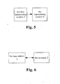
- Fig.5 shows a structure of the base station according to a device example of the present invention.
- the base station comprises a first determining module 2 and a transmitting module 4.
- the functions of the above modules will be described in detail hereinafter.
- the first determining module 2 is adapted to determine the power control parameters of each frequency partition.
- the power control parameters can be the compensation factor or the noise rise target.
- the first determining module 2 is further adapted to determine the power control parameters of each corresponding frequency partition according to an excepted IoT of the adjacent cells in each frequency partition.
- the transmitting module 4 is connected with the first determining module 2, and is adapted to transmit the power control parameters of all or part of the frequency partitions determined by the first determining module 2 to the terminal.
- the work flow of the above modules comprises the processes as follows.
- the first determining module 2 firstly determines the power control parameters of respective frequency partitions.
- the first determining module 2 can determine the power control parameters (namely, the compensation factor, or the noise rise target, or the target ratio of signal to interference and noise, or the target ratio of signal to noise) of each frequency partition of the present cell according to the IoT of the adjacent cells in each frequency partition.
- the detailed determining method can refer to the above formulas 1-12, so unnecessary details will not be given herein any more.
- the transmitting module 4 transmits the power control parameters determined by the first determining module 2 to the terminal in the modes of broadcast, multicast or unicast.
- the base station provided by the example transmits the power control parameters of a plurality of frequency partitions of the uplink frequency band to the terminal.
- the terminal can determine the transmitting power on the sub-carrier included in the corresponding frequency partition according to the power control parameters, so as to improve the uplink interference between the cells effectively.
- a system for controlling an uplink transmitting power is provided according to an example of the present invention.
- the system for controlling the uplink transmitting power comprises a base station and a terminal.
- the base station can be used for realizing the method for controlling the uplink transmitting power provided in the above method examples.
- Fig.6 shows the structure of the system for controlling the uplink transmitting power according to the system example of the present invention.
- the system for controlling the uplink transmitting power according to the system example of the present invention comprises the base station 3 and the terminal 5.
- the functions of the above modules will be described in detail hereinafter.
- the base station 3 comprises: a first determining module which is adapted to determine power control parameters of each frequency partition; and a transmitting module which is connected with the first determining module and is adapted to transmit the power control parameters of all or part of frequency partitions determined by the first determining module to the terminal.
- a first determining module which is adapted to determine power control parameters of each frequency partition
- a transmitting module which is connected with the first determining module and is adapted to transmit the power control parameters of all or part of frequency partitions determined by the first determining module to the terminal.
- the terminal 5 comprises: a receiving module which is adapted to receive the power control parameters transmitted by the base station; and a second determining module which is connected with the receiving module and is adapted to determine an uplink transmitting power on a sub-carrier included in corresponding frequency partition according to the power control parameters received by the receiving module. (The above-mentioned modules are not shown in Fig.6 .)
- the work flow of the system comprises the processes as follows: the first determining module of the base station 3 firstly determines the power control parameters of each frequency partition.
- the first determining module can determine the power control parameters (namely, the compensation factor, or the noise rise target, or the target ratio of signal to interference and noise, or the target ratio of signal to noise) of each frequency partition of the present cell according to the IoT of the adjacent cells in each frequency partition.
- the specific determining methods can refer to the above formulas 1-4 or the above formulas 10-12, so unnecessary details will not be given herein any more.
- the transmitting module transmits the power control parameters determined by the first determining module to the terminal 5 in the modes of broadcast, multicast or unicast.
- the second determining module determines the uplink transmitting power on the sub-carrier included in the corresponding frequency partition according to the power control parameters.
- the specific determining method can refer to the formulas 5-9 or the formula 13, so unnecessary details will not be given herein any more.
- the present invention by transmitting the power control parameters of a plurality of frequency partitions of the uplink frequency band to the terminal, and considering the power control parameters, the present invention ensures the terminal to determine the transmitting power according to the states of different frequency sections of the uplink channel, so as to transmit data or signals to the base station with comparatively proper uplink power, and further control the uplink interference between the cells effectively, and improve the uplink performance of the system.
Landscapes
- Engineering & Computer Science (AREA)
- Signal Processing (AREA)
- Computer Networks & Wireless Communication (AREA)
- Quality & Reliability (AREA)
- Mobile Radio Communication Systems (AREA)
Description
- The present invention relates to the communication field, in particular to a method and a system for controlling an uplink transmitting power, and a base station.
- In a wireless communication system, a base station refers to a device which provides services for a terminal. The base station communicates with the terminal through an uplink/a downlink, wherein the downlink (forward direction) refers to the direction from the base station to the terminal, and the uplink (backward direction) refers to the direction from the terminal to the base station. A plurality of terminals can transmit data to the base station through the uplink at the same time, and can also receive data from the base station through the downlink at the same time.
- In order to further improve the utilization efficiency of the frequency spectrum of the wireless communication system, each cell is required to use the whole frequency resources as much as possible, i.e., the frequency multiplexing factor is 1. However, due to the mutual interference between the users using the same frequency resources in each cell, the uplink interference between the cells has a strong impact on the uplink performance of the wireless communication system. Obviously, to reduce the influence of the uplink interference between the cells to the performance of the system is an important aim of the cellular system design.
- A reasonable power control scheme can effectively control the uplink interference between the cells. For example, in the Long Term Evolution (LTE) standard established by the 3rd Generation Partnership Project (3GPP) standardization organization, a partial link loss compensation factor is introduced into the whole system frequency band to control the power. By the design, the Interference over Thermal Noise Ratio (IoT, thus the interference can also be understood as rise noises) of the uplink of the system is controlled to a relatively stable value, so as to improve the uplink performance of the wireless communication system. While in the Ultra Mobile Broadband (UMB) standard established by the 3GPP2 standardization organization, the terminal determines the available uplink transmitting power to control the uplink interference between the cells according to the uplink interference condition on the whole system frequency band of the received adjacent cell broadcast.
- It can be seen from the above-mentioned description, in the two schemes of the 3GPP and the 3GPP2, the whole uplink frequency resources only have one description variable, i.e., the description variable in the 3GPP scheme is the partial link loss compensation factor, and the description variable in the 3GPP2 scheme is the uplink interference condition on the whole system frequency band of the adjacent cell broadcast namely IoT. In this way, the uplink transmitting power is determined by one resource description variable of the uplink frequency, which will restrict the flexibility of controlling the uplink interference between the cells, and impact the uplink performance of the wireless communication system.
- MOTOROLA: "Uplink Power Control for E-UTRA", 3GPP DRAFT; R1-070795 UL PC FINAL, 3RD GENERATION PARTNERSHIP PROJECT (3GPP), MOBILE COMPETENCE CENTRE; 650, ROUTE DES LUCIOLES; F-06921 SOPHIA-ANTIPOLIS CEDEX; FRANCE, vol. RAN WG1, no. St. Louis, USA; 20070206, 6 February 2007 (2007-02-06),
- LUCENT TECHNOLOGIES: "Uplink Scheduling With Inter-Cell Power Control, with Extensions to Interference Coordination", 3GPP DRAFT; R1-063478, 3RD GENERATION PARTNERSHIP PROJECT (3GPP), MOBILE COMPETENCE CENTRE; 650, ROUTE DES LUCIOLES; F-06921 SOPHIA-ANTIPOLIS CEDEX; FRANCE, vol. RAN WG1, no. Riga, Latvia; 20061102, 2 November 2006 (2006-11-02), XP050103914,
- ZTE: "Uplink Inter-cell Power Control based on Overload Indicator and modified IoT measurement for E-UTRA", 3GPP DRAFT; R1-073596 UPLINK INTER-CELL POWER CONTROL BASED ON OVERLOAD INDICATOR AND MODIFIED IOT MEASUREMENT FOR E-UTRA, 3RD GENERATION PARTNERSHIP PROJECT (3GPP) MOBILE COMPETENCE CENTRE; 650, ROUTE DES LUCIOLES; F-06921 SOPHIA-ANTIPOLIS CEDEX, vol. RAN WG1, no. Athens, Greece; 20070815, 15 August 2007 (2007-08-15), XP050107195, and
- "Interference Constraint Power Control C80216m-08 630", IEEE DRAFT; C80216M-08-630, IEEE-SA, PISCATAWAY, NJ, USA, vol. 802.16m, 7 July 2008 (2008-07-07), pages 1-8, XP017616544 all provide respective technical solutions; however, the above mentioned problem still remains unsolved.
- The present invention is set forth with consideration of the problems in related technology that the methods for controlling the uplink transmitting power is not flexible, and can not effectively improve the uplink performance of the system. For this reason, the present invention mainly aims to provide an improved scheme for controlling the uplink transmitting power to solve at least one of above-mentioned problems in related technology.
- In order to achieve the above-mentioned aim, according to one aspect, the invention provides a method for controlling an uplink transmitting power, characterized by comprising: determining respective power control parameters of each frequency partition in a system whose uplink frequency band is divided into a plurality of frequency partitions, wherein each frequency partition comprises a plurality of physical sub-carriers; and a base station transmitting the power control parameters of all or part of the frequency partitions to a terminal, so that the terminal determines a transmitting power on a sub-carrier included in a corresponding frequency partition according to the power control parameters; wherein the power control parameters comprise a compensation factor; before transmitting the power control parameters to the terminal, for each frequency partition, determining the compensation factor of corresponding frequency partition of present cell according to an expected uplink Interference over Thermal Noise Ratio, IoT, of adjacent cells in the frequency partition; wherein the compensation factor, α, is determined by one of the following formulae: α =min(IoTn )/max(IoTn ), wherein, α is a real number more than or equal to 0 and less than or equal to 1, IoTn is a set of values of the expected IoT of the adjacent cells in the frequency partition;

i is a value of the expected IoT of the i-th adjacent cell in the frequency partition, N is a number of adjacent cells and is a natural number more than or equal to 1;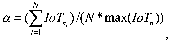
wherein, α is a real number more than or equal to 0 and less than or equal to 1, is a set of values of the expected IoT of the adjacent cells in the frequency partition, IoTn1 is a value of expected IoT of the i-th adjacent cell in the frequency partition, N is a number of adjacent cells and is a natural number more than or equal to 1; and
1 is a value of expected IoT of the i-th adjacent cell in the frequency partition, N is a number of adjacent cells and is a natural number more than or equal to 1 - Preferably, the method further comprises: the terminal determines the transmitting power, PSC , on the sub-carrier by one of the following formulas:


- Preferably, under the circumstance that a plurality of frequency partitions have same compensation factors, transmitting the power control parameters to the terminal comprises: transmitting one of the same compensation factors and identifying the plurality of frequency partitions having the same compensation factors by a frequency partition identifier or a mode of bit mapping.
- Preferably, the terminal receives and analyzes the compensation factor, and determines the transmitting power on the sub-carrier included in the corresponding frequency partition according to the compensation factor, wherein if the terminal fails to receive or analyze the compensation factor, the default value of the compensation factor is 1.
- Preferably, the base station transmits the power control parameters in the modes of broadcast, multicast or unicast.
- According to a second aspect, the invention provides a system for controlling an uplink transmitting power, comprising a base station and a terminal, characterized by, the base station comprising: a first determining module, adapted to determine power control parameters of each frequency partition; a transmitting module, adapted to transmit the power control parameters of all or part of frequency partitions determined by the first determining module to the terminal; the terminal comprising: a receiving module, adapted to receive the power control parameters transmitted by the base station; and a second determining module, adapted to determine an uplink transmitting power on a sub-carrier included in corresponding frequency partition according to the power control parameters received by the receiving module; the power control parameters comprise a compensation factor; and before transmitting the power control parameters to the terminal, the base station (3), for each frequency partition, determining the compensation factor of corresponding frequency partition of present cell according to an expected uplink Interference over Thermal Noise Ratio, loT, of adjacent cells in the frequency partition; wherein the compensation factor, α, is determined by one of the following formulae: α = min(IoTn )/max(IoTn ), wherein, α is a real number more than or equal to 0 and less than or equal to 1, IoTn is a set of values of the expected IoT of the adjacent cells in the frequency partition;

1 is a value of the expected IoT of the i-th adjacent cell in the frequency partition, N is a number of adjacent cells and is a natural number more than or equal to 1;
1 is a value of expected IoT of the i-th adjacent cell in the frequency partition, N is a number of adjacent cells and is a natural number more than or equal to 1; and
1 is a value of expected IoT of the i-th adjacent cell in the frequency partition, N is a number of adjacent cells and is a natural number more than or equal to 1. - In virtue of the technical solution provided by the present invention, by transmitting power control parameters of a plurality of frequency partitions of the uplink frequency band to the terminal, the present invention ensures the terminal to determine the transmitting power on the sub-carrier included in the corresponding frequency partition according to the power control parameters, and can solve the problems that the method for controlling the uplink transmitting power in related technology is not flexible and can not effectively improve the uplink performance of the system, so as to achieve the aims of controlling the uplink interference between the cells effectively and improving the uplink performance of the system.
- Other characteristics and advantages of the present invention will be described in the following specification, and will be apparent partly from the specification, or can be understood by implementing the present invention. The objects and other advantages can be realized and obtained by the structures specified in the specification, claims, and the drawings.
- The drawings herein are used to provide further understanding to the present invention and form a part of the application. The exemplary examples of the present invention and the explanation thereof are used to explain the present invention rather than unduly limit the present invention. In the accompanying drawings:
-
Fig.1 is a flowchart of a method for controlling an uplink transmitting power according to a method example of the present invention; -
Fig.2 is a schematic diagram of a plurality of frequency partitions of an uplink frequency band of a method for controlling an uplink transmitting power according to a method example of the present invention; -
Fig.3 is a specific implementation flowchart of a method for controlling an uplink transmitting power according to a method example of the present invention; -
Fig.4 is another specific implementation flowchart of a method for controlling an uplink transmitting power according to a method example of the present invention; -
Fig.5 is a block diagram of a base station according to a device example of the present invention; -
Fig.6 is a block diagram of a system for controlling an uplink transmitting power according to a system example of the present invention. - With consideration to the problems in related technology that the methods for controlling the uplink transmitting power is not flexible, and can not effectively improve the uplink performance of the system, a mechanism for controlling the uplink transmitting power is provided by examples of the present invention. In the technical schemes provided by the examples of the present invention, by transmitting power control parameters (e.g. a compensation factor, a noise rise target, a target ratio of signal to interference and noise, a target ratio of signal to noise) of a plurality of frequency partitions of an uplink frequency band to the terminal, the present invention ensures the terminal to determine a transmitting power on a sub-carrier included in a corresponding frequency partition according to the power control parameters, so as to transmit data or signals to a base station with proper uplink transmitting power and control uplink interference between cells, and improve uplink performance of the system.
- The examples of the present invention will be described hereinafter in connection with the accompanying drawings. What needs to be explained is that if un-conflictive, the examples of the present invention and technical features thereof can be combined with each other, all of which are concluded in the protection scope of the present invention. In addition, in order to describe the examples conveniently, some step numbers are used in the description hereafter, which are not used to restrict the present invention. Besides, each step described in the following method examples can be executed in an instruction-executable computer system formed by a group of computers. Furthermore, although the flowcharts give the logic sequence, the steps given or described by the examples can be executed in different sequences under certain circumstances.
- A method for controlling an uplink transmitting power is provided according to an example of the present invention.
- ig.1 is a flowchart of the method for controlling the uplink transmitting power according to the method example of the present invention. As shown in
Fig.1 , the method for controlling the uplink transmitting power according to the method example of the present invention comprises steps S102-S104. - Step S102, in a system that all or part of uplink frequency bands are divided into a plurality of frequency partitions, respective power control parameters of each frequency partition are determined, wherein each frequency partition comprises a plurality of physical sub-carriers.
- Step S104, a base station transmits the power control parameters of all or part of the frequency partitions to a terminal, so that the terminal can determine a transmitting power on a sub-carrier included in a corresponding frequency partition according to the power control parameters, wherein the power control parameters comprise but is not limited to: a compensation factor and a noise rise target. Each kind of power control parameter will be described in detail hereinafter.
- By the technical scheme provided by the example, the power control parameters of a plurality of frequency partitions of the uplink frequency bands are transmitted to the terminal, which can ensure the terminal to determine the transmitting power on the sub-carrier included in the corresponding frequency partition according to the power control parameters, so as to improve uplink interference between cells effectively.
- The above-mentioned process will be described in detail hereinafter.
-
Fig.2 is a schematic diagram of a plurality of frequency partitions of an uplink frequency band of the method for controlling the uplink transmitting power according to a method example of the present invention. As shown inFig.2 , the available uplink frequency resources in each cell are divided into four frequency partitions, and each frequency partition has respective uplink target IoT value. In thecell 1, the frequency partitions A and B have lower uplink target IoT value, and the frequency partitions C and D have higher uplink target IoT value. That is to say, for thecell 1, the frequency partitions A and B can only accept smaller uplink interference, while the frequency partitions C and D can accept higher uplink interference. In thecell 2, the frequency partitions A and C have lower uplink target IoT value, and the frequency partitions B and D have higher uplink target IoT value. That is to say, for thecell 2, the frequency partitions A and C can accept smaller uplink interference, while the frequency partitions B and D can accept higher uplink interference. - For a plurality of divided frequency partitions of the uplink frequency bands, the base station determines the power control parameters of each frequency partition respectively, wherein the power control parameters provide reference for the terminal to determine the uplink transmitting power according to the states of different frequency sections of an uplink channel of the present cell.
- Preferably, the base station can also determine the power control parameters of each frequency partition of the present cell according to an IoT in each frequency partition of adjacent cells. In this way, the power control parameters provides further reference for the terminal to determine the uplink transmitting power, so as to provide more effective and flexible reference for improving the interference between the cells. As mentioned above, the power control parameters described in the examples of the present invention can be at least the compensation factor or the noise rise target. Based on the above, the example provides two schemes for the base station to determine the power control parameters of each frequency partition of the present cell according to the IoT in each frequency partition of the adjacent cells. Namely, scheme I, the base station determines the compensation factor of each frequency partition of the present cell according to the IoT in each frequency partition of the adjacent cells; scheme II, the base station determines the noise rise target of each frequency partition of the present cell according to the IoT in each frequency partition of the adjacent cells. The two schemes will be described in detail hereinafter.
- Scheme I, the base station determines the compensation factor of each frequency partition of the present cell according to the IoT in each frequency partition of the adjacent cells.
- Preferably, the base station can figure out the compensation factor according to any one of the following formulas.
-
Formula 1, α = min(IoTn )lmax(IoTn ) wherein α is the compensation factor, and α is a real number more than or equal to 0 and less than or equal to 1, IoTn is a set of values of the expected IoT of the adjacent cells in the frequency partition. -
Formula 2,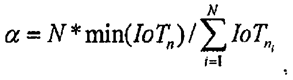
1 is a value of the expected IoT of the i-th adjacent cell in the frequency partition, N is a number of adjacent cells and is a natural number more than or equal to 1. -
Formula 3,
1 is a value of the expected IoT of the i-th adjacent cell in the frequency partition, N is a number of adjacent cells and is a natural number more than or equal to 1. - Formula 4,

i is a value of expected IoT of the i-th adjacent cell in the frequency partition, N is a number of adjacent cells and is a natural number more than or equal to 1. - What needs to be explained is that the formulas 1- 4 are only exemplary. For those common skilled in the art, the other modification modes are easy to be deduced on the basis of the above-mentioned formulas to figure out the compensation factor. However, what should be understood is that any modifications and amendments on the basis of the above-mentioned formulas are all included in the protection scope of the present invention.
- Scheme II, the base station determines the noise rise target of each frequency partition of the present cell according to the IoT in each frequency partition of the adjacent cells.
- In the scheme II, preferably, the base station can figure out the noise rise target according to any one of the following formulas.
- Formula 10, NRT = min(IoTn), wherein, NRT is the noise rise target, IoTn is a set of values of the expected IoT of the adjacent cells in the frequency partition.
- Formula 11,

- Formula 12,

1 is a value of expected IoT of the i-th adjacent cell in the frequency partition, N is a number of adjacent cells and is a natural number more than or equal to 1. - What needs to be explained is that the formulas 10-12 are only exemplary. For those common skilled in the art, the other modification modes are easy to be deduced on the basis of the above-mentioned formulas to figure out the noise rise target. However, what should be understood is that any modifications and amendments on the basis of the above-mentioned formulas are all included in the protection scope of the present invention.
- The base station determines the power control parameters (e.g. the compensation factor or the noise rise target) of each frequency partition of the present cell according to the states of different frequency sections of the uplink channel of the adjacent cells, so as to provide reference for the terminal to determine the uplink transmitting power according to the states of different frequency sections of the uplink channel of the adjacent cells, and provide more effective and flexible reference for improving the interference between the cells.
- After determining the power control parameters, the base station can transmit the power control parameters corresponding to the whole or part of the frequency partitions to the terminal in the modes of broadcast, multicast or unicast.
- Preferably, when a plurality of frequency partitions have a same compensation factor, the base station transmits only the same compensation factor, and can identify the plurality of frequency partitions which have the same compensation factor by giving a frequency partition identifier or a mode of bit mapping.
- After the base station transmits the power control parameters, the terminal can determine the uplink transmitting power on a sub-carrier included in the corresponding frequency partition according to the power control parameters received.
- Preferably, under the circumstance that the terminal does not receive or fails to analyze the compensation factor transmitted by the base station, the default value of the compensation factor will be 1. In the nature of things, the default value can also be set as required or set as the other values. The present invention does not have any limitation to this.
- As mentioned above, the power control parameters described in the examples of the present invention can be at least the compensation factor or the noise rise target. Based on the above, aiming at the above-mentioned scheme I and scheme II, the example provides two schemes for the base station to determine the uplink transmitting power on the sub-carrier included in the corresponding frequency partition according to the power control parameters received. Namely, aiming at the scheme I, the terminal determines the uplink transmitting power on the sub-carrier included in the corresponding frequency partition according to the compensation factor received; aiming at the scheme II, the terminal determines the uplink transmitting power on the sub-carrier included in the corresponding frequency partition according to the noise rise target received. The two schemes will be described in detail hereinafter.
- Aiming at the scheme I, the terminal determines the uplink transmitting power on the sub-carrier included in the corresponding frequency partition according to the compensation factor received.
- Preferably, the terminal can figure out the uplink transmitting power on the sub-carrier included in the corresponding frequency partition according to any one of the following formulas.
-
Formula 5, PSC = min{P max,Pref + α.PL + Δ TF (i) + f(j)}, wherein, PSC is the transmitting power of the terminal on the sub-carrier, Pref is a minimum receiving power required for the base station to guarantee basic quality of a receiving signal, α is the compensation factor, PL is a link loss compensation value determined by the terminal according to receiving quality of a downlink channel, Δ TF (i) is an adjustment parameter related to modulation code grade allocated to the terminal by the base station, i is a grade of transmitting format, the selection of the value of the i is related to the Pref , f(j) is a power adjustment command sent to the terminal by the base station, and the value of the f(j) is more than or equal to 0, j is an identifier of the terminal, preferably, f(j) is optional, P max is a maximum transmitting power of the terminal on the sub-carrier included in the frequency partition. - Formula 6, PSC = min{P max,SINRTARGET + α.PL + N + IoT}, wherein, PSC is the transmitting power of the terminal on the sub-carrier, SINRTARGET is a target ratio of signal to noise required for the base station to receive uplink data normally, α is the compensation factor, PL is a link loss compensation value determined by the terminal according to receiving quality of a downlink channel, N is a thermal noise, IoT is a value of an interference over thermal noise ratio of the base station, N and IoT are notified to the terminal by the base station through a downlink channel, P max is a maximum transmitting power of the terminal on the sub-carrier included in the frequency partition.
- Formula 7, PSC = Pmax *min{1,max[R min,(PL/PLx-tile )α]}, wherein, PSC is the transmitting power of the terminal on the sub-carrier, is a minimum transmitting power measurement factor of the terminal, α is the compensation factor, PL is a link loss compensation value determined by the terminal according to receiving quality of a downlink channel, PLx-tile is a statistical value determined according to link loss condition of the terminal, the value of the PLx-tile is notified to the terminal by the base station through a downlink channel, P max is a maximum transmitting power of the terminal on the sub-carrier included in the frequency partition.
- Formula 8, PSC = min{P max,SINRTARGET + α.PL + N + IoT + Δ power_adjust + σ power_scaling + OffsetICI }, wherein, PSC is the transmitting power of the terminal on the sub-carrier, SINRTARGET is a target ratio of signal to noise required for the base station to receive uplink data normally, α is the compensation factor, PL is a link loss compensation value determined by the terminal according to receiving quality of a downlink channel, N is a thermal noise, IoT is a value of an interference over thermal noise ratio of the base station, N and IoT are notified to the terminal by the base station through a downlink channel, Δ power_adjust is a power adjustment value sent to the terminal by the base station, σpower_adjust is a power adjustment value in a single user transmitting mode or a multi-user transmitting mode, OffsetICI is an adjustment value for adjusting interference between the cells sent by the base station, P max is a maximum transmitting power of the terminal on the sub-carrier included in the frequency partition.
- Formula 9, PSC = min{P max,SlNRTARGET + α.PL + N + IoT + Δ BS + Δ MS }, wherein, PSC is the transmitting power of the terminal on the sub-carrier, SlNRTARGET is a target ratio of signal to noise required for the base station to receive uplink data normally, α is the compensation factor, PL is a link loss compensation value determined by the terminal according to receiving quality of a downlink channel, N is a thermal noise, IoT is a value of an interference over thermal noise ratio of the base station, N and IoT are notified to the terminal by the base station through a downlink channel, Δ BS is a power adjustment value sent to the terminal by the base station, Δ MS is a self-adjustment value of the terminal determined according to condition of a wireless channel, P max is a maximum transmitting power of the terminal on the sub-carrier included in the frequency partition.
- The terminal uses the transmitting power on the sub-carrier to transmit the uplink data, so as to improve the interference between the cells effectively.
- Aiming at the scheme II, the terminal determines the uplink transmitting power on the sub-carrier included in the corresponding frequency partition according to the noise rise target received.
- Based on the scheme II, preferably, the terminal can figure out the uplink transmitting power on the sub-carrier according to the following formula.
- Formula 13, PSC = min{Pmax,NRT + N - g}, wherein, PSC is the transmitting power of the terminal on the sub-carrier, NRT is a value of the noise rise target, N is a thermal noise, the value of N is notified to the terminal by the base station through a downlink channel, g is an equivalent path gain, and is a difference value between a total receiving power of the terminal and a power received from the base station by the terminal, P max is a maximum transmitting power of the terminal on the sub-carrier included in the frequency partition.
- The terminal uses the transmitting power on the sub-carrier to transmit the uplink data, so as to improve the interference between the cells effectively.
- Based on the above description,
Fig.3 is a specific implementation flowchart of the method for controlling the uplink transmitting power according to the method example of the present invention. As shown inFig.3 , the flow comprises steps 302-304. -
Step 302, thecell 1 sends division information of the available uplink frequency resource (the available uplink frequency resource is divided into the frequency partitions A, B, C and D, the division situation of the available uplink frequency resource is as shown inFig.2 ) and the compensation factor values corresponding to respective frequency partitions by a downlink broadcast channel. The specific process can be realized by the operations of the example shown inFig.1 , whereinstep 302 can be corresponding to the step S102. -
Step 304, after receiving the division information, the terminal determines the compensation factors in different frequency partitions, and figures out the transmitting power of the terminal on the sub-carrier included in the corresponding frequency partition according to the formula 9 PSC = min{Pmax,SINRTARGET + α.PL + N + IoT + Δ BS + Δ MS }, wherein, the variable PSC is the transmitting power of the terminal on the sub-carrier, SINRTARGET is a target ratio of signal to noise required for the base station to receive the uplink data normally, α is the compensation factor corresponding to the frequency partition, PL is a link loss compensation value determined by the terminal according to receiving quality of the downlink channel, N is a thermal noise, IoT is a value of an interference over thermal noise ratio of the base station, the variables N and IoT are notified to the terminal by thecell 1 through a downlink channel, Δ BS is a power adjustment value sent to the terminal by thecell 1, Δ MS is a self-adjustment value of the terminal determined according to condition of a wireless channel, P max is a maximum transmitting power of the terminal on the sub-carrier corresponding to the frequency partition. Step 304 can be corresponding to the step S104. - In the
step 302, the compensation factors corresponding to respective uplink frequency partitions in thecell 1 are determined with consideration to a target IoT value in respective corresponding frequency partitions in thecell 2. For example, if thecell 2 requires lower target IoT value (namely smaller cell interference) in the uplink frequency partitions A and C, thecell 1 can set the corresponding compensation factors in the frequency partitions A and C lower; if thecell 2 allows higher target IoT value (namely bigger cell interference) in the uplink frequency partitions B and D, thecell 1 can set the corresponding compensation factors in the frequency partitions B and D higher, so as to control the interference between the cells flexibly. On the contrary, the compensation factors corresponding to respective frequency partitions in thecell 2 are determined with consideration to the target IoT values in respective corresponding frequency partitions in thecell 1. -
Fig.4 is another specific implementation flowchart of the method for controlling the uplink transmitting power according to the method example of the present invention. As shown inFig.4 , the flow comprises steps 402-404. -
Step 402, thecell 2 sends division information of the available uplink frequency resource (the available uplink frequency resource is divided into the frequency partitions A, B, C and D, the division situation of the available uplink frequency resource is as shown inFig.2 ) and the noise rise target values (Target Interference over Thermal, Interference Target, Noise Rise Target) corresponding to respective frequency partitions by a downlink broadcast channel. The specific process can be realized by the operations of the example shown inFig.1 , whereinstep 402 can be corresponding to the step S102. -
Step 404, after receiving the division information, the terminal determines the noise rise target value in different frequency partitions, and figures out the transmitting power of the terminal on the sub-carrier included in the corresponding frequency partition according to the formula 13 PSC = min{P max, NRT + N - g}, wherein, the variable PCS is the transmitting power of the terminal on the sub-carrier, NRT is a value of the noise rise target, N is a thermal noise, the value of N is notified to the terminal by thecell 2 through a downlink channel, g is an equivalent path gain, and is a difference value between a total receiving power of the terminal and a power received from the base station by the terminal, P max is a maximum transmitting power of the terminal on the sub-carrier corresponding to the frequency partition. Step 404 can be corresponding to the step S104. - In the
step 402, the noise rise target value corresponding to respective uplink frequency partitions in thecell 2 are determined with consideration to a target IoT value in respective corresponding frequency partitions in thecell 1. For example, if thecell 1 requires lower target IoT value (namely smaller cell interference) in the uplink frequency partitions A and B, thecell 2 can set the corresponding noise rise target value in the frequency partitions A and B lower; if thecell 1 allows higher target IoT value (namely bigger cell interference) in the uplink frequency partitions C and D, thecell 2 can set the corresponding noise rise target value in the frequency partitions C and D higher, so as to control the interference between the cells flexibly. On the contrary, the noise rise target value corresponding to respective frequency partitions in thecell 1 are determined with consideration to the target IoT value in respective corresponding frequency partitions in thecell 2. - The calculation methods of the uplink transmitting power of the target ratio of signal to interference and noise, and the target ratio of signal to noise on the basis of the whole or part of the frequency partitions follows the calculation methods of the uplink transmitting power on the basis of the noise rise target value, so unnecessary details will not be given herein any more.
- A base station is provided according to an example of the present invention. Preferably, the base station can be used for realizing the method for controlling the uplink transmitting power provided in the above method examples.
-
Fig.5 shows a structure of the base station according to a device example of the present invention. As shown inFig.5 , the base station comprises a first determiningmodule 2 and a transmitting module 4. The functions of the above modules will be described in detail hereinafter. - The first determining
module 2 is adapted to determine the power control parameters of each frequency partition. Preferably, the power control parameters can be the compensation factor or the noise rise target. Preferably, the first determiningmodule 2 is further adapted to determine the power control parameters of each corresponding frequency partition according to an excepted IoT of the adjacent cells in each frequency partition. - The transmitting module 4 is connected with the first determining
module 2, and is adapted to transmit the power control parameters of all or part of the frequency partitions determined by the first determiningmodule 2 to the terminal. - In practical application, the work flow of the above modules comprises the processes as follows. Under the circumstance that the uplink frequency band is divided into a plurality of frequency partitions, the first determining
module 2 firstly determines the power control parameters of respective frequency partitions. Preferably, the first determiningmodule 2 can determine the power control parameters (namely, the compensation factor, or the noise rise target, or the target ratio of signal to interference and noise, or the target ratio of signal to noise) of each frequency partition of the present cell according to the IoT of the adjacent cells in each frequency partition. The detailed determining method can refer to the above formulas 1-12, so unnecessary details will not be given herein any more. Then, the transmitting module 4 transmits the power control parameters determined by the first determiningmodule 2 to the terminal in the modes of broadcast, multicast or unicast. - By setting the first determining
module 2 and the transmitting module 4, the base station provided by the example transmits the power control parameters of a plurality of frequency partitions of the uplink frequency band to the terminal. The terminal can determine the transmitting power on the sub-carrier included in the corresponding frequency partition according to the power control parameters, so as to improve the uplink interference between the cells effectively. - A system for controlling an uplink transmitting power is provided according to an example of the present invention. The system for controlling the uplink transmitting power comprises a base station and a terminal. Preferably, the base station can be used for realizing the method for controlling the uplink transmitting power provided in the above method examples.
-
Fig.6 shows the structure of the system for controlling the uplink transmitting power according to the system example of the present invention. As shown inFig.6 , the system for controlling the uplink transmitting power according to the system example of the present invention comprises thebase station 3 and theterminal 5. The functions of the above modules will be described in detail hereinafter. - The
base station 3 comprises: a first determining module which is adapted to determine power control parameters of each frequency partition; and a transmitting module which is connected with the first determining module and is adapted to transmit the power control parameters of all or part of frequency partitions determined by the first determining module to the terminal. (The above-mentioned modules are not shown inFig.6 , and the functions of the above modules are similar to the functions of the modules shown inFig.5 , so unnecessary details will not be given herein any more.) - The
terminal 5 comprises: a receiving module which is adapted to receive the power control parameters transmitted by the base station; and a second determining module which is connected with the receiving module and is adapted to determine an uplink transmitting power on a sub-carrier included in corresponding frequency partition according to the power control parameters received by the receiving module. (The above-mentioned modules are not shown inFig.6 .) - In practical application, the work flow of the system comprises the processes as follows: the first determining module of the
base station 3 firstly determines the power control parameters of each frequency partition. Preferably, the first determining module can determine the power control parameters (namely, the compensation factor, or the noise rise target, or the target ratio of signal to interference and noise, or the target ratio of signal to noise) of each frequency partition of the present cell according to the IoT of the adjacent cells in each frequency partition. The specific determining methods can refer to the above formulas 1-4 or the above formulas 10-12, so unnecessary details will not be given herein any more. Then, the transmitting module transmits the power control parameters determined by the first determining module to theterminal 5 in the modes of broadcast, multicast or unicast. After theterminal 5 receives the power control parameters transmitted by thebase station 3 through the receiving module, the second determining module determines the uplink transmitting power on the sub-carrier included in the corresponding frequency partition according to the power control parameters. The specific determining method can refer to the formulas 5-9 or the formula 13, so unnecessary details will not be given herein any more. - All in all, in virtue of the technical scheme provided by the present invention, by transmitting the power control parameters of a plurality of frequency partitions of the uplink frequency band to the terminal, and considering the power control parameters, the present invention ensures the terminal to determine the transmitting power according to the states of different frequency sections of the uplink channel, so as to transmit data or signals to the base station with comparatively proper uplink power, and further control the uplink interference between the cells effectively, and improve the uplink performance of the system.
- The descriptions above are only preferable examples of the present invention, which are not used to restrict the present invention. For those skilled in the art, the present invention may have various changes and variations. Any amendments, equivalent substitutions, improvements etc. within the present invention are all concluded in the scope of protection of the present invention.
Claims (6)
- A method for controlling an uplink transmitting power, comprising:determining respective power control parameters of each frequency partition in a system whose uplink frequency band is divided into a plurality of frequency partitions, wherein each frequency partition comprises a plurality of physical sub-carriers; anda base station transmitting the power control parameters of all or part of the frequency partitions to a terminal, so that the terminal determines a transmitting power on a sub-carrier included in a corresponding frequency partition according to the power control parameters;whereinthe power control parameters comprise a compensation factor; and before transmitting the power control parameters to the terminal, the method further comprises: for each frequency partition, determining the compensation factor of corresponding frequency partition of present cell according to an expected uplink Interference over Thermal Noise Ration, IoT, of adjacent cells in the frequency partition; wherein the compensation factor, α, is determined by one of the following formulas: α= min(IoTn )/max(IoTn ), wherein, α is a real number more than or equal to 0 and less than or equal to 1, IoTn is a set of values of the expected IoT of the adjacent cells in the frequency partition;

1 is a value of the expected IoT of the i-th adjacent cell in the frequency partition, N is a number of adjacent cells and is a natural number more than or equal to 1;
1 is a value of expected IoT of the i-th adjacent cell in the frequency partition, N is a number of adjacent cells and is a natural number more than or equal to 1; and
1 is a value of expected IoT of the i-th adjacent cell in the frequency partition, N is a number of adjacent cells and is a natural number more than or equal to 1. - The method according to Claim 1, characterized in that the method further comprises:the terminal determines the transmitting power, PSC , on the sub-carrier by one of the following formulas:


- The method according to Claim 2, characterized in that under the circumstance that a plurality of frequency partitions have same compensation factors, transmitting the power control parameters to the terminal comprises:transmitting one of the same compensation factors and identifying the plurality of frequency partitions having the same compensation factors by a frequency partition identifier or a mode of bit mapping.
- The method according to Claim 2, characterized in that the method further comprises:the terminal receives and analyzes the compensation factor, and determines the transmitting power on the sub-carrier included in the corresponding frequency partition according to the compensation factor, wherein if the terminal fails to receive or analyze the compensation factor, the default value of the compensation factor is 1.
- The method according to any one of Claims 1-2, characterized in that the base station transmits the power control parameters in the modes of broadcast, multicast or unicast.
- A system for controlling an uplink transmitting power, comprising a base station (3) and a terminal (5),
the base station (3) comprising:a first determining module (2), adapted to determine power control parameters of each frequency partition;a transmitting module (4), adapted to transmit the power control parameters of all or part of frequency partitions determined by the first determining module to the terminal; the terminal (5) comprising:a receiving module, adapted to receive the power control parameters transmitted by the base station; anda second determining module, adapted to determine an uplink transmitting power on a sub-carrier included in corresponding frequency partition according to the power control parameters received by the receiving module;whereinthe power control parameters comprise a compensation factor; and before transmitting the power control parameters to the terminal, the base station (3) further configured to: for each frequency partition, determine the compensation factor of corresponding frequency partition of present cell according to an expected uplink Interference over Thermal Noise Ration, IoT, of adjacent cells in the frequency partition; wherein the compensation factor , α, is determined by one of the following formulas: α = min(IoT n)/max(IoTn ), wherein, α is a real number more than or equal to 0 and less than or equal to 1, IoTn is a set of values of the expected IoT of the adjacent cells in the frequency partition;
1 is a value of the expected IoT of the i-th adjacent cell in the frequency partition, N is a number of adjacent cells and is a natural number more than or equal to 1;
i is a value of expected IoT of the i-th adjacent cell in the frequency partition, N is a number of adjacent cells and is a natural number more than or equal to 1; and
i is a value of expected IoT of the i-th adjacent cell in the frequency partition, N is a number of adjacent cells and is a natural number more than or equal to 1.
Applications Claiming Priority (2)
| Application Number | Priority Date | Filing Date | Title |
|---|---|---|---|
| CN200810172303.6A CN101729104B (en) | 2008-10-31 | 2008-10-31 | Method and system for controlling uplink transmitting power as well as base station |
| PCT/CN2009/070777 WO2010048798A1 (en) | 2008-10-31 | 2009-03-13 | A method and a system for controlling the uplink transmission power, and a base station |
Publications (3)
| Publication Number | Publication Date |
|---|---|
| EP2352354A1 EP2352354A1 (en) | 2011-08-03 |
| EP2352354A4 EP2352354A4 (en) | 2013-11-13 |
| EP2352354B1 true EP2352354B1 (en) | 2015-10-21 |
Family
ID=42128206
Family Applications (1)
| Application Number | Title | Priority Date | Filing Date |
|---|---|---|---|
| EP09822991.7A Active EP2352354B1 (en) | 2008-10-31 | 2009-03-13 | A method and a system for controlling the uplink transmission power |
Country Status (5)
| Country | Link |
|---|---|
| US (1) | US8909281B2 (en) |
| EP (1) | EP2352354B1 (en) |
| KR (1) | KR20110091502A (en) |
| CN (1) | CN101729104B (en) |
| WO (1) | WO2010048798A1 (en) |
Families Citing this family (19)
| Publication number | Priority date | Publication date | Assignee | Title |
|---|---|---|---|---|
| CN102281571B (en) * | 2010-06-11 | 2015-01-14 | 电信科学技术研究院 | Power control method and equipment |
| KR20110139078A (en) * | 2010-06-22 | 2011-12-28 | 삼성전자주식회사 | Method and apparatus for determining reverse transmission output in mobile communication system |
| US9167584B2 (en) * | 2010-12-02 | 2015-10-20 | Lg Electronics Inc. | Method and apparatus for allocating resources in a multi-node system |
| CN102740421B (en) * | 2011-04-15 | 2017-10-27 | 中兴通讯股份有限公司 | A kind of Poewr control method and system |
| CN102143567B (en) * | 2011-04-22 | 2014-12-10 | 中兴通讯股份有限公司 | Power-regulating method and device |
| CN102905356B (en) * | 2011-07-28 | 2015-06-24 | 上海贝尔股份有限公司 | Heterogeneous mobile communication network power control method |
| CN102271390A (en) * | 2011-08-01 | 2011-12-07 | 中兴通讯股份有限公司 | Method and system for controlling outer loop power |
| CN102497663B (en) * | 2011-12-13 | 2014-08-13 | 北京邮电大学 | Femtocell power control method and control device |
| WO2013099643A1 (en) * | 2011-12-27 | 2013-07-04 | 日本電気株式会社 | Receiving power estimation device, receiving power estimation method, program, sensor station, and wireless system |
| CN103686971B (en) * | 2012-09-19 | 2017-09-29 | 联芯科技有限公司 | The method and apparatus of LTE system uplink transmission power control |
| KR101510829B1 (en) * | 2012-10-24 | 2015-04-10 | 에스케이텔레콤 주식회사 | Method for interference cancelation based on uplink carrier aggregation, and appratus applied to the same |
| WO2014098408A1 (en) * | 2012-12-20 | 2014-06-26 | 주식회사 팬택 | Apparatus and method for controlling power imbalance in wireless communication system |
| CN104780599A (en) * | 2014-01-14 | 2015-07-15 | 中国移动通信集团公司 | Method and device for controlling uplink power |
| CN107027178A (en) * | 2016-02-01 | 2017-08-08 | 中兴通讯股份有限公司 | A kind of ascending power optimizing distribution method, device and mobile terminal |
| CN109792694A (en) * | 2017-04-21 | 2019-05-21 | 深圳市大疆创新科技有限公司 | Transmitting power control for wireless communication system |
| CN110035485B (en) * | 2018-01-11 | 2022-11-22 | 华为技术有限公司 | Uplink information transmission method and device |
| CN111182618B (en) * | 2018-11-09 | 2021-11-19 | 中国移动通信有限公司研究院 | Data transmission method, sending end equipment and receiving end equipment |
| CN111278099B (en) * | 2019-01-18 | 2021-04-30 | 维沃移动通信有限公司 | Power control method, terminal and network side equipment |
| CN114172593B (en) * | 2021-11-04 | 2024-12-17 | 杭州涂鸦信息技术有限公司 | Power calibration method, calibration equipment and calibration system of wireless module |
Family Cites Families (10)
| Publication number | Priority date | Publication date | Assignee | Title |
|---|---|---|---|---|
| US6735451B1 (en) * | 2000-11-09 | 2004-05-11 | Telefonaktlebolaget Lm Ericsson (Publ) | Method and apparatus for providing downlink power control in radio communication systems employing virtual cells |
| US7162250B2 (en) * | 2003-05-16 | 2007-01-09 | International Business Machines Corporation | Method and apparatus for load sharing in wireless access networks based on dynamic transmission power adjustment of access points |
| US7826435B1 (en) * | 2004-03-05 | 2010-11-02 | Zte (Usa) Inc. | Power control in OFDM and OFDMA wireless communication networks |
| EP1734773A1 (en) * | 2005-06-14 | 2006-12-20 | Alcatel | A method for uplink interference coordination in single frequency networks, a base station a mobile terminal and a mobile network therefor |
| US7965789B2 (en) * | 2005-08-22 | 2011-06-21 | Qualcomm Incorporated | Reverse link power control for an OFDMA system |
| CN1917393A (en) * | 2006-08-31 | 2007-02-21 | 华为技术有限公司 | Method and device for controlling up going transmission power |
| WO2008093621A1 (en) * | 2007-01-31 | 2008-08-07 | Sharp Kabushiki Kaisha | Mobile communication system, base station device, and mobile station device |
| CN101237260B (en) * | 2007-02-02 | 2011-11-30 | 中兴通讯股份有限公司 | Uplink power control device and method |
| US8126403B2 (en) * | 2008-04-23 | 2012-02-28 | Telefonaktiebolaget Lm Ericsson (Publ) | Estimating and limiting inter-cell interference |
| CN101272172B (en) * | 2008-05-09 | 2013-01-16 | 中兴通讯股份有限公司 | Road loss compensation factor configuration method and device |
-
2008
- 2008-10-31 CN CN200810172303.6A patent/CN101729104B/en active Active
-
2009
- 2009-03-13 WO PCT/CN2009/070777 patent/WO2010048798A1/en not_active Ceased
- 2009-03-13 KR KR1020117009097A patent/KR20110091502A/en not_active Ceased
- 2009-03-13 EP EP09822991.7A patent/EP2352354B1/en active Active
- 2009-03-13 US US13/126,383 patent/US8909281B2/en active Active
Also Published As
| Publication number | Publication date |
|---|---|
| EP2352354A4 (en) | 2013-11-13 |
| US20120004006A1 (en) | 2012-01-05 |
| US8909281B2 (en) | 2014-12-09 |
| CN101729104B (en) | 2013-03-27 |
| KR20110091502A (en) | 2011-08-11 |
| WO2010048798A1 (en) | 2010-05-06 |
| CN101729104A (en) | 2010-06-09 |
| EP2352354A1 (en) | 2011-08-03 |
Similar Documents
| Publication | Publication Date | Title |
|---|---|---|
| US8909281B2 (en) | Method and system for controlling an uplink transmitting power, and a base station | |
| US20220210772A1 (en) | Control information obtaining method and apparatus | |
| Malik et al. | Radio resource management scheme in NB-IoT systems | |
| US11121814B2 (en) | Techniques of CSI feedback with unequal error protection messages | |
| EP3711430B1 (en) | Physical layer enhancements for early data transmission | |
| US10499342B2 (en) | Method of controlling transmit power of uplink channel in wireless communication system and apparatus therefor | |
| TWI594649B (en) | Method and arrangement for uplink power control | |
| US9113419B2 (en) | Methods and apparatus for downlink PDSCH power setting | |
| TWI526102B (en) | Method of controlling uplink transmission power at ue in wireless communication system and apparatus thereof | |
| EP4195846A1 (en) | Method and device for transmitting and receiving uplink in wireless communication system | |
| US10595279B2 (en) | Power control method and device | |
| US20120020334A1 (en) | Method, apparatus, and system for multi-antenna transmission | |
| CN111901875A (en) | Indication method, uplink transmission method, device, service node, terminal and medium | |
| CN104519576A (en) | Mobile terminal and data transmission method in wireless community | |
| EP3089384B1 (en) | Method for feeding back channel quality indicator in wireless communication system and apparatus therefor | |
| CN102165714A (en) | Method for transmitting control information in a wireless communication system | |
| US11109370B2 (en) | Method for transmitting data in next generation communication system, and device therefor | |
| CN102724744B (en) | Downlink transmission power allocation method for cooperative transmission equipment in coordinated multi-point transmission system | |
| EP3975440A1 (en) | Methods and apparatuses for signaling framework for flexible beam management | |
| EP3618299B1 (en) | Method for measuring interference in next generation communication system and apparatus therefor | |
| Yassine et al. | Investigation on narrowband IoT link adaptation with rate and energy objectives | |
| EP4661514A1 (en) | Method and device used for wireless communication | |
| US20250261175A1 (en) | Communication apparatus and communication method for feedback response transmission in indicated frequency domain | |
| CN108574982A (en) | A kind of method and apparatus in the user equipment for being used for power adjustment, base station | |
| US20240340677A1 (en) | Method and apparatus for reporting channel state information to reduce wireless power |
Legal Events
| Date | Code | Title | Description |
|---|---|---|---|
| PUAI | Public reference made under article 153(3) epc to a published international application that has entered the european phase |
Free format text: ORIGINAL CODE: 0009012 |
|
| 17P | Request for examination filed |
Effective date: 20110524 |
|
| AK | Designated contracting states |
Kind code of ref document: A1 Designated state(s): AT BE BG CH CY CZ DE DK EE ES FI FR GB GR HR HU IE IS IT LI LT LU LV MC MK MT NL NO PL PT RO SE SI SK TR |
|
| DAX | Request for extension of the european patent (deleted) | ||
| A4 | Supplementary search report drawn up and despatched |
Effective date: 20131014 |
|
| RIC1 | Information provided on ipc code assigned before grant |
Ipc: H04W 52/14 20090101ALI20131008BHEP Ipc: H04W 52/24 20090101ALI20131008BHEP Ipc: H04W 80/00 20090101AFI20131008BHEP |
|
| 17Q | First examination report despatched |
Effective date: 20140619 |
|
| GRAP | Despatch of communication of intention to grant a patent |
Free format text: ORIGINAL CODE: EPIDOSNIGR1 |
|
| GRAS | Grant fee paid |
Free format text: ORIGINAL CODE: EPIDOSNIGR3 |
|
| INTG | Intention to grant announced |
Effective date: 20150817 |
|
| GRAA | (expected) grant |
Free format text: ORIGINAL CODE: 0009210 |
|
| AK | Designated contracting states |
Kind code of ref document: B1 Designated state(s): AT BE BG CH CY CZ DE DK EE ES FI FR GB GR HR HU IE IS IT LI LT LU LV MC MK MT NL NO PL PT RO SE SI SK TR |
|
| REG | Reference to a national code |
Ref country code: GB Ref legal event code: FG4D Ref country code: NL Ref legal event code: MP Effective date: 20151021 |
|
| REG | Reference to a national code |
Ref country code: CH Ref legal event code: EP |
|
| REG | Reference to a national code |
Ref country code: AT Ref legal event code: REF Ref document number: 757376 Country of ref document: AT Kind code of ref document: T Effective date: 20151115 |
|
| REG | Reference to a national code |
Ref country code: IE Ref legal event code: FG4D |
|
| REG | Reference to a national code |
Ref country code: DE Ref legal event code: R096 Ref document number: 602009034405 Country of ref document: DE |
|
| REG | Reference to a national code |
Ref country code: LT Ref legal event code: MG4D |
|
| REG | Reference to a national code |
Ref country code: AT Ref legal event code: MK05 Ref document number: 757376 Country of ref document: AT Kind code of ref document: T Effective date: 20151021 |
|
| PG25 | Lapsed in a contracting state [announced via postgrant information from national office to epo] |
Ref country code: IT Free format text: LAPSE BECAUSE OF FAILURE TO SUBMIT A TRANSLATION OF THE DESCRIPTION OR TO PAY THE FEE WITHIN THE PRESCRIBED TIME-LIMIT Effective date: 20151021 Ref country code: NL Free format text: LAPSE BECAUSE OF FAILURE TO SUBMIT A TRANSLATION OF THE DESCRIPTION OR TO PAY THE FEE WITHIN THE PRESCRIBED TIME-LIMIT Effective date: 20151021 Ref country code: NO Free format text: LAPSE BECAUSE OF FAILURE TO SUBMIT A TRANSLATION OF THE DESCRIPTION OR TO PAY THE FEE WITHIN THE PRESCRIBED TIME-LIMIT Effective date: 20160121 Ref country code: ES Free format text: LAPSE BECAUSE OF FAILURE TO SUBMIT A TRANSLATION OF THE DESCRIPTION OR TO PAY THE FEE WITHIN THE PRESCRIBED TIME-LIMIT Effective date: 20151021 Ref country code: LT Free format text: LAPSE BECAUSE OF FAILURE TO SUBMIT A TRANSLATION OF THE DESCRIPTION OR TO PAY THE FEE WITHIN THE PRESCRIBED TIME-LIMIT Effective date: 20151021 Ref country code: IS Free format text: LAPSE BECAUSE OF FAILURE TO SUBMIT A TRANSLATION OF THE DESCRIPTION OR TO PAY THE FEE WITHIN THE PRESCRIBED TIME-LIMIT Effective date: 20160221 Ref country code: HR Free format text: LAPSE BECAUSE OF FAILURE TO SUBMIT A TRANSLATION OF THE DESCRIPTION OR TO PAY THE FEE WITHIN THE PRESCRIBED TIME-LIMIT Effective date: 20151021 |
|
| PG25 | Lapsed in a contracting state [announced via postgrant information from national office to epo] |
Ref country code: PT Free format text: LAPSE BECAUSE OF FAILURE TO SUBMIT A TRANSLATION OF THE DESCRIPTION OR TO PAY THE FEE WITHIN THE PRESCRIBED TIME-LIMIT Effective date: 20160222 Ref country code: FI Free format text: LAPSE BECAUSE OF FAILURE TO SUBMIT A TRANSLATION OF THE DESCRIPTION OR TO PAY THE FEE WITHIN THE PRESCRIBED TIME-LIMIT Effective date: 20151021 Ref country code: AT Free format text: LAPSE BECAUSE OF FAILURE TO SUBMIT A TRANSLATION OF THE DESCRIPTION OR TO PAY THE FEE WITHIN THE PRESCRIBED TIME-LIMIT Effective date: 20151021 Ref country code: PL Free format text: LAPSE BECAUSE OF FAILURE TO SUBMIT A TRANSLATION OF THE DESCRIPTION OR TO PAY THE FEE WITHIN THE PRESCRIBED TIME-LIMIT Effective date: 20151021 Ref country code: SE Free format text: LAPSE BECAUSE OF FAILURE TO SUBMIT A TRANSLATION OF THE DESCRIPTION OR TO PAY THE FEE WITHIN THE PRESCRIBED TIME-LIMIT Effective date: 20151021 Ref country code: LV Free format text: LAPSE BECAUSE OF FAILURE TO SUBMIT A TRANSLATION OF THE DESCRIPTION OR TO PAY THE FEE WITHIN THE PRESCRIBED TIME-LIMIT Effective date: 20151021 Ref country code: GR Free format text: LAPSE BECAUSE OF FAILURE TO SUBMIT A TRANSLATION OF THE DESCRIPTION OR TO PAY THE FEE WITHIN THE PRESCRIBED TIME-LIMIT Effective date: 20160122 |
|
| REG | Reference to a national code |
Ref country code: DE Ref legal event code: R097 Ref document number: 602009034405 Country of ref document: DE |
|
| PG25 | Lapsed in a contracting state [announced via postgrant information from national office to epo] |
Ref country code: CZ Free format text: LAPSE BECAUSE OF FAILURE TO SUBMIT A TRANSLATION OF THE DESCRIPTION OR TO PAY THE FEE WITHIN THE PRESCRIBED TIME-LIMIT Effective date: 20151021 |
|
| PLBE | No opposition filed within time limit |
Free format text: ORIGINAL CODE: 0009261 |
|
| STAA | Information on the status of an ep patent application or granted ep patent |
Free format text: STATUS: NO OPPOSITION FILED WITHIN TIME LIMIT |
|
| PG25 | Lapsed in a contracting state [announced via postgrant information from national office to epo] |
Ref country code: EE Free format text: LAPSE BECAUSE OF FAILURE TO SUBMIT A TRANSLATION OF THE DESCRIPTION OR TO PAY THE FEE WITHIN THE PRESCRIBED TIME-LIMIT Effective date: 20151021 Ref country code: BE Free format text: LAPSE BECAUSE OF NON-PAYMENT OF DUE FEES Effective date: 20160331 Ref country code: SK Free format text: LAPSE BECAUSE OF FAILURE TO SUBMIT A TRANSLATION OF THE DESCRIPTION OR TO PAY THE FEE WITHIN THE PRESCRIBED TIME-LIMIT Effective date: 20151021 Ref country code: DK Free format text: LAPSE BECAUSE OF FAILURE TO SUBMIT A TRANSLATION OF THE DESCRIPTION OR TO PAY THE FEE WITHIN THE PRESCRIBED TIME-LIMIT Effective date: 20151021 Ref country code: RO Free format text: LAPSE BECAUSE OF FAILURE TO SUBMIT A TRANSLATION OF THE DESCRIPTION OR TO PAY THE FEE WITHIN THE PRESCRIBED TIME-LIMIT Effective date: 20151021 |
|
| 26N | No opposition filed |
Effective date: 20160722 |
|
| REG | Reference to a national code |
Ref country code: DE Ref legal event code: R119 Ref document number: 602009034405 Country of ref document: DE |
|
| PG25 | Lapsed in a contracting state [announced via postgrant information from national office to epo] |
Ref country code: LU Free format text: LAPSE BECAUSE OF FAILURE TO SUBMIT A TRANSLATION OF THE DESCRIPTION OR TO PAY THE FEE WITHIN THE PRESCRIBED TIME-LIMIT Effective date: 20160313 Ref country code: MC Free format text: LAPSE BECAUSE OF FAILURE TO SUBMIT A TRANSLATION OF THE DESCRIPTION OR TO PAY THE FEE WITHIN THE PRESCRIBED TIME-LIMIT Effective date: 20151021 |
|
| REG | Reference to a national code |
Ref country code: CH Ref legal event code: PL |
|
| PG25 | Lapsed in a contracting state [announced via postgrant information from national office to epo] |
Ref country code: SI Free format text: LAPSE BECAUSE OF FAILURE TO SUBMIT A TRANSLATION OF THE DESCRIPTION OR TO PAY THE FEE WITHIN THE PRESCRIBED TIME-LIMIT Effective date: 20151021 |
|
| REG | Reference to a national code |
Ref country code: IE Ref legal event code: MM4A |
|
| PG25 | Lapsed in a contracting state [announced via postgrant information from national office to epo] |
Ref country code: BE Free format text: LAPSE BECAUSE OF FAILURE TO SUBMIT A TRANSLATION OF THE DESCRIPTION OR TO PAY THE FEE WITHIN THE PRESCRIBED TIME-LIMIT Effective date: 20151021 |
|
| REG | Reference to a national code |
Ref country code: FR Ref legal event code: ST Effective date: 20161130 |
|
| PG25 | Lapsed in a contracting state [announced via postgrant information from national office to epo] |
Ref country code: LI Free format text: LAPSE BECAUSE OF NON-PAYMENT OF DUE FEES Effective date: 20160331 Ref country code: DE Free format text: LAPSE BECAUSE OF NON-PAYMENT OF DUE FEES Effective date: 20161001 Ref country code: IE Free format text: LAPSE BECAUSE OF NON-PAYMENT OF DUE FEES Effective date: 20160313 Ref country code: FR Free format text: LAPSE BECAUSE OF NON-PAYMENT OF DUE FEES Effective date: 20160331 Ref country code: CH Free format text: LAPSE BECAUSE OF NON-PAYMENT OF DUE FEES Effective date: 20160331 |
|
| PG25 | Lapsed in a contracting state [announced via postgrant information from national office to epo] |
Ref country code: MT Free format text: LAPSE BECAUSE OF FAILURE TO SUBMIT A TRANSLATION OF THE DESCRIPTION OR TO PAY THE FEE WITHIN THE PRESCRIBED TIME-LIMIT Effective date: 20151021 |
|
| PG25 | Lapsed in a contracting state [announced via postgrant information from national office to epo] |
Ref country code: HU Free format text: LAPSE BECAUSE OF FAILURE TO SUBMIT A TRANSLATION OF THE DESCRIPTION OR TO PAY THE FEE WITHIN THE PRESCRIBED TIME-LIMIT; INVALID AB INITIO Effective date: 20090313 Ref country code: CY Free format text: LAPSE BECAUSE OF FAILURE TO SUBMIT A TRANSLATION OF THE DESCRIPTION OR TO PAY THE FEE WITHIN THE PRESCRIBED TIME-LIMIT Effective date: 20151021 |
|
| PG25 | Lapsed in a contracting state [announced via postgrant information from national office to epo] |
Ref country code: MK Free format text: LAPSE BECAUSE OF FAILURE TO SUBMIT A TRANSLATION OF THE DESCRIPTION OR TO PAY THE FEE WITHIN THE PRESCRIBED TIME-LIMIT Effective date: 20151021 Ref country code: MT Free format text: LAPSE BECAUSE OF FAILURE TO SUBMIT A TRANSLATION OF THE DESCRIPTION OR TO PAY THE FEE WITHIN THE PRESCRIBED TIME-LIMIT Effective date: 20160331 Ref country code: TR Free format text: LAPSE BECAUSE OF FAILURE TO SUBMIT A TRANSLATION OF THE DESCRIPTION OR TO PAY THE FEE WITHIN THE PRESCRIBED TIME-LIMIT Effective date: 20151021 |
|
| PG25 | Lapsed in a contracting state [announced via postgrant information from national office to epo] |
Ref country code: BG Free format text: LAPSE BECAUSE OF FAILURE TO SUBMIT A TRANSLATION OF THE DESCRIPTION OR TO PAY THE FEE WITHIN THE PRESCRIBED TIME-LIMIT Effective date: 20151021 |
|
| P01 | Opt-out of the competence of the unified patent court (upc) registered |
Free format text: CASE NUMBER: APP_12604/2025 Effective date: 20250314 |
|
| PGFP | Annual fee paid to national office [announced via postgrant information from national office to epo] |
Ref country code: GB Payment date: 20260106 Year of fee payment: 18 |