EP2352310A1 - Improved self-cooling loudspeaker - Google Patents
Improved self-cooling loudspeaker Download PDFInfo
- Publication number
- EP2352310A1 EP2352310A1 EP09717324A EP09717324A EP2352310A1 EP 2352310 A1 EP2352310 A1 EP 2352310A1 EP 09717324 A EP09717324 A EP 09717324A EP 09717324 A EP09717324 A EP 09717324A EP 2352310 A1 EP2352310 A1 EP 2352310A1
- Authority
- EP
- European Patent Office
- Prior art keywords
- core ring
- loudspeaker
- permanent magnet
- coil
- cooling
- Prior art date
- Legal status (The legal status is an assumption and is not a legal conclusion. Google has not performed a legal analysis and makes no representation as to the accuracy of the status listed.)
- Withdrawn
Links
Images


Classifications
-
- H—ELECTRICITY
- H04—ELECTRIC COMMUNICATION TECHNIQUE
- H04R—LOUDSPEAKERS, MICROPHONES, GRAMOPHONE PICK-UPS OR LIKE ACOUSTIC ELECTROMECHANICAL TRANSDUCERS; ELECTRIC HEARING AIDS; PUBLIC ADDRESS SYSTEMS
- H04R9/00—Transducers of moving-coil, moving-strip, or moving-wire type
- H04R9/02—Details
- H04R9/022—Cooling arrangements
-
- H—ELECTRICITY
- H04—ELECTRIC COMMUNICATION TECHNIQUE
- H04R—LOUDSPEAKERS, MICROPHONES, GRAMOPHONE PICK-UPS OR LIKE ACOUSTIC ELECTROMECHANICAL TRANSDUCERS; ELECTRIC HEARING AIDS; PUBLIC ADDRESS SYSTEMS
- H04R9/00—Transducers of moving-coil, moving-strip, or moving-wire type
- H04R9/06—Loudspeakers
-
- H—ELECTRICITY
- H04—ELECTRIC COMMUNICATION TECHNIQUE
- H04R—LOUDSPEAKERS, MICROPHONES, GRAMOPHONE PICK-UPS OR LIKE ACOUSTIC ELECTROMECHANICAL TRANSDUCERS; ELECTRIC HEARING AIDS; PUBLIC ADDRESS SYSTEMS
- H04R9/00—Transducers of moving-coil, moving-strip, or moving-wire type
- H04R9/02—Details
- H04R9/025—Magnetic circuit
Definitions
- the object of the present invention relates to an electrodynamic-type self-cooling loudspeaker, although optionally, it may also be any other type of loudspeaker.
- an electrodynamic loudspeaker consists of a mobile electric coil disposed in the circular air gap of a closed, permanent and fixed magnetic circuit.
- alternating electric current passes through the coil, alternating electric forces in accordance with said alternating current are generated in said coil; said forces make the coil vibrate (by virtue of its mobility) and transmit said vibrations, either to a membrane or to an acoustic screen whereto it is attached, thereby generating the sound which is transmitted to the surrounding air.
- the magnetic circuit of a loudspeaker consists of, at least, three basic elements: a cylindrical permanent magnet and two polar parts.
- One of these (the upper polar part) is a cylindrical "core ring” having temporary magnetism (manufactured from “soft” iron or similar) disposed on the permanent magnet, while the other (the lower polar part) is a return vessel (in charge of closing the magnetic circuit) having a circular base, whereon the permanent magnet is in turn disposed.
- the air gap which houses the mobile coil is the circular space left between the outer cylindrical face of the "core ring" and the upper part of the inner cylindrical face of the return vessel.
- the electrical energy consumed by a loudspeaker depends on the current circulating through its coil, which in turn depends, in the broad sense, on loudspeaker impedance and, specifically, on the electrical resistance of its coil.
- all the electrical energy that reaches the loudspeaker should be transformed into acoustic energy, but this does not occur as most of said energy is transformed into heat; said heat, generated within the mobile coil Itself, is a consequence of the Joule effect due to the passage of the electric current through the turns of said coil.
- the heat generated causes two negative effects in the loudspeaker.
- the heating of the coil produces an increase in the electrical resistance of its turns (by virtue of the positive temperature coefficient of the metals from which it is usually manufactured), which causes a decrease in electrical intensity and, therefore, in the power that reaches the loudspeaker. This causes a decrease in loudspeaker sound level which is known as "power compression-induced loss.”
- Evacuation of this heat is normally carried out through natural transfer due to temperature gradient from the coil to the fixed components near it (i.e. towards the polar parts of the permanent magnet) through the air gap; finally, the heat passes from said parts and/or from the permanent magnet towards the exterior to the atmosphere. Therefore, it is a relatively low-speed passive heat transfer, due to the relatively low thermal conductivity of the iron and other ferromagnetic materials, which are normally used in the manufacture of the constituent elements of the magnetic circuit of the loudspeaker.
- the novel improved self-cooling loudspeaker that is the object of the present technical specification has been designed for the purpose of overcoming the aforementioned drawbacks.
- the present invention relates to a new loudspeaker model which, having self-cooling capacity, allows increases in power of at least 35% compared to other models with similar features, quality and price.
- the new loudspeaker is manufactured In such a manner that its magnetic circuit has a spiral grooving in the air gap on either side of the mobile coil.
- the oscillating movement of the coil itself transmitted to the "dust cap" of the acoustic membrane, acts as a reciprocating pump that impels the forced cooling air; therefore, said forced air is made to circulate back and forth along the interior of a cooling system of which the spiral grooving of the air gap forms part.
- the cooling of the mobile coil is much more effective, as the cooling air, forced to circulate around the coil and on either side thereof, along the interior of the spiral grooves, is directly in contact therewith for a much longer period of time; therefore, heat transfer by contact between the cooling air and the coil is much more efficient.
- the new loudspeaker has a magnetic circuit composed of three basic elements: a cylindrical permanent magnet and two polar parts, upper and lower; the upper polar part is a cylindrical "core ring” having a spiral grooving on its outer cylindrical face; said "core ring” is disposed on the permanent magnet; the lower polar part is a return vessel (in charge of closing the magnetic circuit) having a circular base and a spiral grooving on the upper part of its inner cylindrical face, coincident with the grooving of the "core ring”; in turn, the permanent magnet is disposed on the return vessel.
- the air gap which houses the mobile coil, is the spirally grooved circular space left between the outer cylindrical face of the "core ring" and the upper part of the inner cylindrical face of the return vessel.
- the "core ring” also has a central pass-through orifice which, in addition to serving as an additional cooling orifice, also serves to alleviate the excessive compression that could occur (in the case of vibrations caused by loud sounds) between the "core ring” and the “dust cap” of the membrane, as said compression is counterproductive to some loudspeaker elements.
- the "core ring” has additional cooling pass-through orifices.
- the new improved setf-cooling loudspeaker consists of a magnetic circuit composed of a cylindrical permanent magnet (1) and two polar parts (2 and 3), one of which is a cylindrical "core ring" (2) disposed on the permanent magnet (1), while the other polar part is a return vessel (3) having a circular base, whereon the permanent magnet (1) is in turn disposed.
- the novel loudspeaker is characterised in that the "core ring" (2) has a plurality of spiral grooves (4) on its outer cylindrical face, while the return vessel (3) also has a plurality of spiral grooves (5) on the upper part of its inner cylindrical face, coincident with the grooving (4) of the "core ring” (2).
- the coil (10) is housed within the air gap constituted between the outer cylindrical face of the "core ring" (2) and the inner cylindrical face of the return vessel
- the "core ring” (2) has additional cooling pass-through orifices (9) and also has a central pass-through orifice (11) which, in addition to serving as an additional cooling orifice, also serves to alleviate the excessive compression waves that could occur between the "core ring” (2) and the "dust cap” (6) of the membrane (7), as said excessive compression is counterproductive to some loudspeaker elements.
Landscapes
- Physics & Mathematics (AREA)
- Engineering & Computer Science (AREA)
- Acoustics & Sound (AREA)
- Signal Processing (AREA)
- Audible-Bandwidth Dynamoelectric Transducers Other Than Pickups (AREA)
Abstract
Description
- The object of the present invention, as expressed in the title of this specification, relates to an electrodynamic-type self-cooling loudspeaker, although optionally, it may also be any other type of loudspeaker.
- In principle, an electrodynamic loudspeaker consists of a mobile electric coil disposed in the circular air gap of a closed, permanent and fixed magnetic circuit. When an alternating electric current passes through the coil, alternating electric forces in accordance with said alternating current are generated in said coil; said forces make the coil vibrate (by virtue of its mobility) and transmit said vibrations, either to a membrane or to an acoustic screen whereto it is attached, thereby generating the sound which is transmitted to the surrounding air.
- Generally speaking, the magnetic circuit of a loudspeaker consists of, at least, three basic elements: a cylindrical permanent magnet and two polar parts. One of these (the upper polar part) is a cylindrical "core ring" having temporary magnetism (manufactured from "soft" iron or similar) disposed on the permanent magnet, while the other (the lower polar part) is a return vessel (in charge of closing the magnetic circuit) having a circular base, whereon the permanent magnet is in turn disposed. In this case, the air gap which houses the mobile coil is the circular space left between the outer cylindrical face of the "core ring" and the upper part of the inner cylindrical face of the return vessel.
- Normally, the electrical energy consumed by a loudspeaker depends on the current circulating through its coil, which in turn depends, in the broad sense, on loudspeaker impedance and, specifically, on the electrical resistance of its coil. Ideally, all the electrical energy that reaches the loudspeaker should be transformed into acoustic energy, but this does not occur as most of said energy is transformed into heat; said heat, generated within the mobile coil Itself, is a consequence of the Joule effect due to the passage of the electric current through the turns of said coil.
- The heat generated causes two negative effects in the loudspeaker.
- Firstly, the heating of the coil produces an increase in the electrical resistance of its turns (by virtue of the positive temperature coefficient of the metals from which it is usually manufactured), which causes a decrease in electrical intensity and, therefore, in the power that reaches the loudspeaker. This causes a decrease in loudspeaker sound level which is known as "power compression-induced loss."
- Secondly, if the heating is excessive, in addition to the previous effect there can be a second and worse effect which consists of the possibility that the coil may burn, rendering the loudspeaker useless.
- Evacuation of this heat is normally carried out through natural transfer due to temperature gradient from the coil to the fixed components near it (i.e. towards the polar parts of the permanent magnet) through the air gap; finally, the heat passes from said parts and/or from the permanent magnet towards the exterior to the atmosphere. Therefore, it is a relatively low-speed passive heat transfer, due to the relatively low thermal conductivity of the iron and other ferromagnetic materials, which are normally used in the manufacture of the constituent elements of the magnetic circuit of the loudspeaker.
- In order to avoid the drawback represented by the accumulation of heat in the coil and the two aforementioned negative effects entailed, some more advanced models have vertical notches or slots on the outer cylindrical face of the "core ring", which allow vertical circulation of air between the mobile coil and the "core ring."
- However, this procedure is not very effective and barely increases heat evacuation capacity compared to other, more traditional loudspeaker models.
- The novel improved self-cooling loudspeaker that is the object of the present technical specification has been designed for the purpose of overcoming the aforementioned drawbacks.
- Generally speaking, the present invention relates to a new loudspeaker model which, having self-cooling capacity, allows increases in power of at least 35% compared to other models with similar features, quality and price.
- The new loudspeaker is manufactured In such a manner that its magnetic circuit has a spiral grooving in the air gap on either side of the mobile coil. The oscillating movement of the coil itself, transmitted to the "dust cap" of the acoustic membrane, acts as a reciprocating pump that impels the forced cooling air; therefore, said forced air is made to circulate back and forth along the interior of a cooling system of which the spiral grooving of the air gap forms part.
- In this manner, the cooling of the mobile coil is much more effective, as the cooling air, forced to circulate around the coil and on either side thereof, along the interior of the spiral grooves, is directly in contact therewith for a much longer period of time; therefore, heat transfer by contact between the cooling air and the coil is much more efficient.
- In essence, the new loudspeaker has a magnetic circuit composed of three basic elements: a cylindrical permanent magnet and two polar parts, upper and lower; the upper polar part is a cylindrical "core ring" having a spiral grooving on its outer cylindrical face; said "core ring" is disposed on the permanent magnet; the lower polar part is a return vessel (in charge of closing the magnetic circuit) having a circular base and a spiral grooving on the upper part of its inner cylindrical face, coincident with the grooving of the "core ring"; in turn, the permanent magnet is disposed on the return vessel.
- In this manner, the air gap, which houses the mobile coil, is the spirally grooved circular space left between the outer cylindrical face of the "core ring" and the upper part of the inner cylindrical face of the return vessel.
- The "core ring" also has a central pass-through orifice which, in addition to serving as an additional cooling orifice, also serves to alleviate the excessive compression that could occur (in the case of vibrations caused by loud sounds) between the "core ring" and the "dust cap" of the membrane, as said compression is counterproductive to some loudspeaker elements.
- Optionally, the "core ring" has additional cooling pass-through orifices.
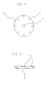
- With the object of illustrating the foregoing, a set of drawings has been included as an integral part of the present specification, wherein a solely explanatory but non-limiting example of practical embodiment of the characteristics of the novel invention has been represented In a simplified and schematic manner:
- Fig.1
- hows a side and exploded view of the different constituent elements of the novel loudspeaker, wherein a cross-section of the return vessel coil, membrane and "dust cap" attached thereto can be observed;
- Fig. 2
- shows the magnetic circuit assembled, but separated from the coil and its screen;
- Fig. 3
- shows all the elements assembled in their final positions; it also shows the cooling outgoing air flow during the movement of the screen towards the magnet; during the reverse movement of the screen, the air flow would be the contrary, i.e. incoming; and
- Figs. 4 and 5
- show a plan and side view, respectively, of the "core ring."
- A practical embodiment of the device that is the object of the present specification is described, by way of example, in the attached figures.
- The new improved setf-cooling loudspeaker, of the electrodynamic type, consists of a magnetic circuit composed of a cylindrical permanent magnet (1) and two polar parts (2 and 3), one of which is a cylindrical "core ring" (2) disposed on the permanent magnet (1), while the other polar part is a return vessel (3) having a circular base, whereon the permanent magnet (1) is in turn disposed.
- The novel loudspeaker is characterised in that the "core ring" (2) has a plurality of spiral grooves (4) on its outer cylindrical face, while the return vessel (3) also has a plurality of spiral grooves (5) on the upper part of its inner cylindrical face, coincident with the grooving (4) of the "core ring" (2).
- The coil (10) is housed within the air gap constituted between the outer cylindrical face of the "core ring" (2) and the inner cylindrical face of the return vessel
- The oscillating movement of the coil (10) itself, transmitted to the "dust cap" (6) of the membrane (7), is used as a reciprocating pump for impelling the forced cooling air (8) back and forth.
- The "core ring" (2) has additional cooling pass-through orifices (9) and also has a central pass-through orifice (11) which, in addition to serving as an additional cooling orifice, also serves to alleviate the excessive compression waves that could occur between the "core ring" (2) and the "dust cap" (6) of the membrane (7), as said excessive compression is counterproductive to some loudspeaker elements.
- The materials used to manufacture the different constituent elements of the present invention shall be independent of the object thereof, In addition to the shapes, dimensions and accessories thereof , and may be replaced by other technically equivalent materials, provided that they do not affect the essentiality of the invention nor differ from the scope defined in the claims section.
- Having established the expressed concept, the claims are expounded below, thereby summarising the novelties being claimed:
Claims (2)
- Electrodynamic-type improved self-cooling loudspeaker consisting of a magnetic circuit composed of a cylindrical permanent magnet (1) and two polar parts (2 and 3), one of which is a cylindrical "core ring" (2) disposed on the permanent magnet (1), while the other polar part is a "return valve" (3) having a circular base, whereon the permanent magnet (1) is in turn disposed, essentially characterised in that the "core ring" (2) has a plurality of spiral grooves (4) on its outer cylindrical face, while the return vessel (3) also has a plurality of spiral grooves (5) on the upper part of its inner cylindrical face, coincident with the grooving (4) of the "core ring" (2).
- Improved seff-cooring loudspeaker, according to the preceding claim, characterised in that, optionally, the "core ring" (2) has additional cooling pass-through orifices (9).
Applications Claiming Priority (2)
| Application Number | Priority Date | Filing Date | Title |
|---|---|---|---|
| ES200800649A ES2325518B1 (en) | 2008-03-05 | 2008-03-05 | PERFECTED SELF-COOLED SPEAKER. |
| PCT/ES2009/000083 WO2009109675A1 (en) | 2008-03-05 | 2009-02-12 | Improved self-cooling loudspeaker |
Publications (2)
| Publication Number | Publication Date |
|---|---|
| EP2352310A1 true EP2352310A1 (en) | 2011-08-03 |
| EP2352310A4 EP2352310A4 (en) | 2013-04-03 |
Family
ID=41044992
Family Applications (1)
| Application Number | Title | Priority Date | Filing Date |
|---|---|---|---|
| EP09717324A Withdrawn EP2352310A4 (en) | 2008-03-05 | 2009-02-12 | Improved self-cooling loudspeaker |
Country Status (8)
| Country | Link |
|---|---|
| US (1) | US20100316248A1 (en) |
| EP (1) | EP2352310A4 (en) |
| CN (1) | CN102027759A (en) |
| BR (1) | BRPI0905998A2 (en) |
| CA (1) | CA2716045A1 (en) |
| ES (1) | ES2325518B1 (en) |
| RU (1) | RU2010140123A (en) |
| WO (1) | WO2009109675A1 (en) |
Families Citing this family (4)
| Publication number | Priority date | Publication date | Assignee | Title |
|---|---|---|---|---|
| JP2013132094A (en) * | 2011-12-20 | 2013-07-04 | Shimano Inc | Hub shell, rotor and bicycle power generator hub |
| CN114151323A (en) * | 2021-12-07 | 2022-03-08 | 冯超超 | A heat dissipation structure of a diaphragm pump |
| US12156006B2 (en) | 2022-05-09 | 2024-11-26 | B&C Speakers S.P.A | Acoustic compression chamber with modally coupled annular diaphragm |
| CN119211816A (en) * | 2024-09-20 | 2024-12-27 | 维沃移动通信有限公司 | Sound components and electronics |
Family Cites Families (11)
| Publication number | Priority date | Publication date | Assignee | Title |
|---|---|---|---|---|
| JPS57136896A (en) * | 1981-02-18 | 1982-08-24 | Ibuki Kogyo Kk | Horn speaker |
| US5497428A (en) * | 1994-11-01 | 1996-03-05 | Rojas; Omar E. | Self-cooled magnetic structure for loudspeakers |
| ATE364979T1 (en) * | 1995-04-18 | 2007-07-15 | Harman Int Ind | COIL PAIR DRIVE WITH MULTIPURPOSE HOUSING |
| US5909015A (en) * | 1998-03-26 | 1999-06-01 | Yamamoto; Shuji | Self-cooled loudspeaker |
| CA2270726A1 (en) * | 1998-09-08 | 2000-03-08 | The Canadian Loudspeaker Corporation | Loudspeaker |
| CA2245351A1 (en) * | 1998-09-08 | 2000-03-08 | The Canadian Loudspeaker Corporation | Forced air cooling system |
| US6721435B2 (en) * | 2000-02-22 | 2004-04-13 | Babb Laboratories | Acoustic loudspeaker with energy absorbing bearing and voice coil, and selective sound dampening and dispersion |
| US20020094104A1 (en) * | 2001-01-16 | 2002-07-18 | Bush Michael Eugene | Loudspeaker cooling device |
| US6678387B2 (en) * | 2001-10-30 | 2004-01-13 | Alpine Electronics, Inc. | Loudspeaker having cooling system |
| US7634101B2 (en) * | 2006-01-31 | 2009-12-15 | Alpine Electronics, Inc | Thermal management system for loudspeaker having internal heat sink and vented top plate |
| US8014555B2 (en) * | 2006-03-28 | 2011-09-06 | Harman International Industries, Incorporated | Self-cooling electromagnetic transducer |
-
2008
- 2008-03-05 ES ES200800649A patent/ES2325518B1/en active Active
-
2009
- 2009-02-12 RU RU2010140123/28A patent/RU2010140123A/en not_active Application Discontinuation
- 2009-02-12 EP EP09717324A patent/EP2352310A4/en not_active Withdrawn
- 2009-02-12 CN CN2009801079130A patent/CN102027759A/en active Pending
- 2009-02-12 WO PCT/ES2009/000083 patent/WO2009109675A1/en not_active Ceased
- 2009-02-12 US US12/866,787 patent/US20100316248A1/en not_active Abandoned
- 2009-02-12 BR BRPI0905998-9A patent/BRPI0905998A2/en not_active IP Right Cessation
- 2009-02-12 CA CA2716045A patent/CA2716045A1/en not_active Abandoned
Also Published As
| Publication number | Publication date |
|---|---|
| ES2325518B1 (en) | 2010-07-20 |
| WO2009109675A1 (en) | 2009-09-11 |
| EP2352310A4 (en) | 2013-04-03 |
| ES2325518A1 (en) | 2009-09-07 |
| RU2010140123A (en) | 2012-04-10 |
| CN102027759A (en) | 2011-04-20 |
| BRPI0905998A2 (en) | 2015-06-30 |
| US20100316248A1 (en) | 2010-12-16 |
| CA2716045A1 (en) | 2009-09-11 |
Similar Documents
| Publication | Publication Date | Title |
|---|---|---|
| RU2367114C2 (en) | Magnetic circuit with double magnet, loud-speaker and device for generating oscillations using such magnetic circuit | |
| US5909015A (en) | Self-cooled loudspeaker | |
| US20040086144A1 (en) | Subwoofer | |
| EP2352310A1 (en) | Improved self-cooling loudspeaker | |
| US11937061B2 (en) | Audio transducer with forced ventilation of motor and method | |
| CN105376671B (en) | A speaker and terminal | |
| KR200443212Y1 (en) | Bone conduction speaker with dual coil structure | |
| US20090010470A1 (en) | Resonating Speaker | |
| JP3985987B2 (en) | Speaker device and cooling device for speaker device | |
| US9282410B2 (en) | Transducer motor structure with enhanced flux | |
| US11930340B2 (en) | System for cooling the stationary winding of an induction motor | |
| EP2801217A1 (en) | Motor for dynamic loudspeaker | |
| US7978872B2 (en) | Driver for a speaker | |
| CN201504310U (en) | Double power coupling inner magnetic electric speaker | |
| CN210298060U (en) | Self-cooled magnetic circuit system | |
| CN104767423B (en) | electric motor | |
| CN104507022A (en) | Telephone receiver capable of enhancing low-frequency audio output | |
| CN110430491B (en) | A scented speaker | |
| US20020094104A1 (en) | Loudspeaker cooling device | |
| CN201904712U (en) | DC linear motor with light weight and large thrust force | |
| KR101131807B1 (en) | Magnetic circuit for coin converters | |
| JP5987171B2 (en) | Electric blower | |
| JP2013201721A (en) | Magnetic circuit for speaker | |
| JP2012142345A (en) | Superconducting apparatus | |
| JP3165693U (en) | Speaker |
Legal Events
| Date | Code | Title | Description |
|---|---|---|---|
| PUAI | Public reference made under article 153(3) epc to a published international application that has entered the european phase |
Free format text: ORIGINAL CODE: 0009012 |
|
| 17P | Request for examination filed |
Effective date: 20110120 |
|
| AK | Designated contracting states |
Kind code of ref document: A1 Designated state(s): AT BE BG CH CY CZ DE DK EE ES FI FR GB GR HR HU IE IS IT LI LT LU LV MC MK MT NL NO PL PT RO SE SI SK TR |
|
| DAX | Request for extension of the european patent (deleted) | ||
| RBV | Designated contracting states (corrected) |
Designated state(s): AT BE BG CH CY CZ DE DK EE ES FI FR GB GR HR HU IE IS IT LI LT LU LV MC MK MT NL NO PL PT RO SE SI SK TR |
|
| A4 | Supplementary search report drawn up and despatched |
Effective date: 20130305 |
|
| RIC1 | Information provided on ipc code assigned before grant |
Ipc: H04R 9/06 20060101AFI20130227BHEP Ipc: H04R 9/02 20060101ALI20130227BHEP |
|
| GRAP | Despatch of communication of intention to grant a patent |
Free format text: ORIGINAL CODE: EPIDOSNIGR1 |
|
| GRAJ | Information related to disapproval of communication of intention to grant by the applicant or resumption of examination proceedings by the epo deleted |
Free format text: ORIGINAL CODE: EPIDOSDIGR1 |
|
| GRAP | Despatch of communication of intention to grant a patent |
Free format text: ORIGINAL CODE: EPIDOSNIGR1 |
|
| RIC1 | Information provided on ipc code assigned before grant |
Ipc: H04R 9/02 20060101ALI20130430BHEP Ipc: H04R 9/06 20060101AFI20130430BHEP |
|
| DAX | Request for extension of the european patent (deleted) | ||
| INTG | Intention to grant announced |
Effective date: 20130523 |
|
| INTG | Intention to grant announced |
Effective date: 20130603 |
|
| STAA | Information on the status of an ep patent application or granted ep patent |
Free format text: STATUS: THE APPLICATION IS DEEMED TO BE WITHDRAWN |
|
| 18D | Application deemed to be withdrawn |
Effective date: 20131015 |