EP2351997A1 - Device for measuring level of molten metal and method thereof - Google Patents
Device for measuring level of molten metal and method thereof Download PDFInfo
- Publication number
- EP2351997A1 EP2351997A1 EP08877654A EP08877654A EP2351997A1 EP 2351997 A1 EP2351997 A1 EP 2351997A1 EP 08877654 A EP08877654 A EP 08877654A EP 08877654 A EP08877654 A EP 08877654A EP 2351997 A1 EP2351997 A1 EP 2351997A1
- Authority
- EP
- European Patent Office
- Prior art keywords
- measuring
- molten metal
- lifting mechanism
- measuring probe
- level
- Prior art date
- Legal status (The legal status is an assumption and is not a legal conclusion. Google has not performed a legal analysis and makes no representation as to the accuracy of the status listed.)
- Withdrawn
Links
Images
Classifications
-
- G—PHYSICS
- G01—MEASURING; TESTING
- G01F—MEASURING VOLUME, VOLUME FLOW, MASS FLOW OR LIQUID LEVEL; METERING BY VOLUME
- G01F23/00—Indicating or measuring liquid level or level of fluent solid material, e.g. indicating in terms of volume or indicating by means of an alarm
- G01F23/22—Indicating or measuring liquid level or level of fluent solid material, e.g. indicating in terms of volume or indicating by means of an alarm by measuring physical variables, other than linear dimensions, pressure or weight, dependent on the level to be measured, e.g. by difference of heat transfer of steam or water
-
- B—PERFORMING OPERATIONS; TRANSPORTING
- B22—CASTING; POWDER METALLURGY
- B22D—CASTING OF METALS; CASTING OF OTHER SUBSTANCES BY THE SAME PROCESSES OR DEVICES
- B22D2/00—Arrangement of indicating or measuring devices, e.g. for temperature or viscosity of the fused mass
- B22D2/003—Arrangement of indicating or measuring devices, e.g. for temperature or viscosity of the fused mass for the level of the molten metal
-
- G—PHYSICS
- G01—MEASURING; TESTING
- G01F—MEASURING VOLUME, VOLUME FLOW, MASS FLOW OR LIQUID LEVEL; METERING BY VOLUME
- G01F23/00—Indicating or measuring liquid level or level of fluent solid material, e.g. indicating in terms of volume or indicating by means of an alarm
- G01F23/04—Indicating or measuring liquid level or level of fluent solid material, e.g. indicating in terms of volume or indicating by means of an alarm by dip members, e.g. dip-sticks
-
- G—PHYSICS
- G01—MEASURING; TESTING
- G01F—MEASURING VOLUME, VOLUME FLOW, MASS FLOW OR LIQUID LEVEL; METERING BY VOLUME
- G01F23/00—Indicating or measuring liquid level or level of fluent solid material, e.g. indicating in terms of volume or indicating by means of an alarm
- G01F23/80—Arrangements for signal processing
- G01F23/802—Particular electronic circuits for digital processing equipment
- G01F23/804—Particular electronic circuits for digital processing equipment containing circuits handling parameters other than liquid level
-
- G—PHYSICS
- G01—MEASURING; TESTING
- G01F—MEASURING VOLUME, VOLUME FLOW, MASS FLOW OR LIQUID LEVEL; METERING BY VOLUME
- G01F23/00—Indicating or measuring liquid level or level of fluent solid material, e.g. indicating in terms of volume or indicating by means of an alarm
- G01F23/22—Indicating or measuring liquid level or level of fluent solid material, e.g. indicating in terms of volume or indicating by means of an alarm by measuring physical variables, other than linear dimensions, pressure or weight, dependent on the level to be measured, e.g. by difference of heat transfer of steam or water
- G01F23/28—Indicating or measuring liquid level or level of fluent solid material, e.g. indicating in terms of volume or indicating by means of an alarm by measuring physical variables, other than linear dimensions, pressure or weight, dependent on the level to be measured, e.g. by difference of heat transfer of steam or water by measuring the variations of parameters of electromagnetic or acoustic waves applied directly to the liquid or fluent solid material
- G01F23/284—Electromagnetic waves
- G01F23/292—Light, e.g. infrared or ultraviolet
Definitions
- the present invention relates to an apparatus for measuring the liquid level of molten metal such as molten steel and a method of measuring the liquid level of molten metal by using the apparatus.
- the level of the liquid metal is also a critical factor in many processes.
- the liquid steel level in a tundish plays a role in determining the cast-on time, preventing the flux slag from getting into billet/slab and improving the melt-to-shop ratio. It is hard to measure exactly the liquid steel level, as a slag layer cover the surface of liquid steel and the slag layer thickness is uncertain.
- a publicly known arrangement is the weighing method in which the calculation and determination of the liquid steel level is based on weighing out the total weight of the tundish and the molten steel (including slag layer) and some known parameters such as the weight and cubage of the tundish, and liquid steel density, etc.
- the calculated liquid level is soften inaccurate since the thickness of the slag layer has also been included in the measurement value of the liquid steel level due to uncertain slag weight.
- Further measuring deviation of the liquid steel level is also inevitable since the tundish lining can be eroded inch by inch by molten steel resulting in an irregular change of the capacity of the tundish. Namely, it is almost impossible to determine the accurate correspondence relation between the of the total weight of the tundish and the liquid level, so the liquid level of molten metal can hardly be calculated accurately
- a method of measuring the liquid level of molten steel in the ladles has been published, as disclosed in Ger Pat. No. DE2945251-A1 "Measuring level of liquid steel in ladles etc. - using laser beam directed at surface at angle to axis of imaging system".
- a laser beam is incident upon the surface of slag layer floating on the molten steel so as to form a laser bright spot therein.
- the position height of the laser bright spot is detected by the imaging system as a measurement of liquid level of molten steel, and the displacement of the laser spot in vertical direction indicates a variation of the level of the liquid steel.
- a liquid level measuring apparatus for molten metal of the type which comprises an image measuring device, a measuring probe, a lifting mechanism, a displacement sensor, a data processing system and a correction marker.
- the lifting mechanism is mounted on the molten metal container, or is independent of the molten metal container.
- the image measuring device is mounted on the lifting mechanism or is independent of the lifting mechanism, the optical axis of the image measuring devices is set at an angle with the geometric axis of the measuring probe;
- the measuring probe is mounted on the lifting mechanism, or is independent of the lifting mechanism, the measuring probe is located within the range of the field of view of the image measuring device.
- the image device, the lifting mechanism and the displacement sensor are connected to the data processing system respectively.
- the lifting mechanism comprises a lifting drive device, a lifting gearing connected to the lifting drive device, a bracket connected to the lifting gearing, and a fixture mounted on the bracket with which the measuring probe is vertically held.
- the measuring probe is made of high-temperature refractories, such as MgO-C, or AL 2 O 3 -C, or AL 2 O 3 -C-Zr, or MgO-C-Zr, or of metal with melting point above 800 °C, and is formed into a rod or tube or strip, the total length of the measuring probe is more than 100mm longer than the thickness of the slag layer.
- high-temperature refractories such as MgO-C, or AL 2 O 3 -C, or AL 2 O 3 -C-Zr, or MgO-C-Zr, or of metal with melting point above 800 °C
- the measuring probe is a temperature measuring tube as a temperature sensor, in operation, which is used synchronously for the continuous temperature measurement and the level measurement of liquid steel in a tundish.
- the correction marker is an annulation with more than 1 mm but less than 50 mm in thickness and more than 1 mm but less than 100 mm in height, or a clubbed or tubular or lathy object with more than 10 mm but less than 1500 mm in length and more than 2 mm but less than 200 mm in equivalent diameter, which is made of refractory materials, such as AL 2 O 3 -C, or MgO-C, or AL 2 O 3 -C-Zr, or MgO-C-Zr, or of metal with melting point above 500 °C.
- refractory materials such as AL 2 O 3 -C, or MgO-C, or AL 2 O 3 -C-Zr, or MgO-C-Zr, or of metal with melting point above 500 °C.
- the correction marker is hung from the bracket in the lifting mechanism, or is fixed to the non-dipping portion of the measuring probe, or is mounted on the cover or the inner wall of the molten metal container, or in a suitable place independent of the molten metal container and/or the liquid level measuring apparatus where can be able to be recognized and located by the image measuring device.
- the displacement sensor is connected to the lifting mechanism; the displacement sensor is a tension rod, or a pull rope, or a resistance-type, or a photoelectric encoder-type or an image displacement sensor.
- a technical arrangement characterized in that the optical axis of the image measuring device is set at an angle of 15°-70° with the geometric axis of the measuring probe.
- the image measuring device can be a line array or a planar (or area) array or a point-scanning type camera, or a thermal imager.
- a preferred technical arrangement characterized in that the image measuring device is assembly housed within a cooling jacket, and a dust-proof guard is mounted in the front end thereof.
- Another object of the present invention is to provide a method of measuring accurately the thickness of slag layer floating on molten metal and then the liquid level of molten metal.
- a method of measuring the liquid level of molten metal comprising the steps of:
- a preferred technical arrangement characterized in that the optical axis of the image measuring device is set at an angle of 15°-70° with the geometric axis of the measuring probe.
- a preferred technical arrangement characterized in that the same or separate image measuring devices can be used to measure the thickness of the slag layer described in step (2) and the height of the surface level of the slag layer described in step (4).
- the measuring processes of the liquid level of molten metal are as follows:
- the measuring probe is in the state of immerging in the molten metal.
- the image measuring device can continuously captures the images of the top surface of the slag layer around the measuring probe, and the data processing system can determine the level height of the surface of the slag layer. So the molten metal level can also be obtained by the slag surface level and the above obtained thickness of the slag layer.
- the image measuring device used is a video camera.
- the angle between the optical axis of the camera and the geometric axis of the measuring probe has large influence on the resolution of the camera. The smaller the angle, the lower is the resolution. Conversely, the larger the angle, the higher is the resolution, but the smaller is the imaged area of the measuring probe. An angle range of 15°-70° is optimal.
- the image measuring device To enable the image measuring device to operate stably and reliably in harsh on-site environment, it is assembly housed within a cooling jacket, and a dust-proof guard is installed in the front end of it.
- Thermal conductivity of materials of the measuring probe and its geometric size determine the temperature sensing speed of the measuring probe in inserting state and thermodiffusion speed in raising state thereof. The lower the temperature sensing speed of the measuring probe, the longer is the measuring time, but the faster is the disappearance speed of the temperature gradient boundaries at said two interface positions when the measuring probe was raised, so as to be not capable of measuring the level of the liquid metal.
- the measuring probe in accordance with the present invention is of high-temperature refractory materials with a proper thermal conductivity, such as AL 2 O 3 -C, or MgO-C, or AL 2 O 3 -C-Zr, or MgO-C-Zr, or of metal with melting point above 800 °C, which can be formed into a rod or tube or strip, the total length of the measuring probe is more than 100 mm longer than the thickness of the slag layer.
- the correction marker has one or several characteristic signs, which is hung from the bracket of the lifting mechanism, or is fixed to the non-dipping portion of the measuring probe or the cover of molten metal container or its inner wall above the level of the molten metal, or in a place being independent of the molten metal container and/or the liquid level measuring apparatus where may be recognized and located by the image measuring device.
- the correction marker is to be used for correcting a measurement error resulting from change of the relative position between the image measuring device and the measuring probe.
- the relative position between the image measuring device and the measuring probe varies from the predetermined location relationship due to some causes such as vibration and /or mechanical deformation of the lifting mechanism in high temperature environment, which will results in a change of the position or/and shape of the correction marker in the image display screen of the camera or the thermal imager, and an error is produced in a measurement value of the level of the liquid metal without correction.
- the predetermined relative position between the image measurement device and the measuring probe can be calculated according to change of the position and shape of the correction marker such as change of the position coordinates, arc curvature, direction, or dimensions, and thereby the measuring error of the liquid level will be corrected.
- a liquid level measuring apparatus for molten steel comprises an image measuring device 5, a measuring probe 6, a lifting mechanism 1 a displacement sensor 11, a data processing system 4 and a correction marker 7 which is a metallic ring fixed to the non-dipping portion of the measuring probe 6 and is used to correct the change of relative position between the image measuring device 5 and the measuring probe 6.
- the lifting mechanism 1 is fixed to the outer wall of a tundish 10 (a molten steel container) for the continuous casting of the steel.
- the measuring probe 6 is vertically hung from the bracket 2 of the lifting mechanism 1 by the fixture 3, and can move up and down with the bracket driven by a motor to be inserted into molten steel 9 or to be raised from it.
- the displacement sensor 11 is used to measure the raised height of the measuring probe 6, and fed it back to the data processing system 4.
- the image measuring device 5 is also installed in the bracket 2 of the lifting mechanism 1 and the lifted portion of the measuring probe 6 from the molten metal 9 and the ring-shaped correction marker 7 are all located within the field of view of the image measuring device 5.
- the measuring processes of the temperature of liquid steel are as follows:
- the measuring probe 6 driven by the lifting mechanism 1 moves downwards and inserts vertically into the measured molten steel 9 in the tundish 10 to a predetermined depth through the interface of the slag layer 8 and liquid steel 9, and the image measuring device 5 captures the images of the surface of the slag layer 8 around the measuring probe 6. And while the measuring probe 6 reaches or approaches a thermal equilibrium with the liquid steel 9 and the slag layer 8, the measuring probe 6 is rapidly elevated and the lifted height is more than the thickness of the slag layer 8, the lifting height is measured by the displacement sensor 11 and is transferred to the data processing system 4. At one time, the image measuring device 5 captures the thermal of the lifted portion of the measuring probe 6, and then the measuring probe 6 is afresh inserted into the molten steed 9.
- the above images are transferred to the data processing system 4 and is processed, analyzed and calculated, and the level heights of the slag-steel interface and the air-slag interface can be determined and then thickness of the layer is obtained.
- the image measuring device 5 can continuously capture the images of the top surface of the slag layer 8 around the measuring probe 6, and the data processing system can determine the level height of the surface of the slag layer. So the liquid steel level can also be obtained continuously based on the slag surface level and the above obtained thickness of the slag layer or the level heights of said two interfaces.
- the image measuring device 5 includes a planar array CCD detector and an optical system (not shown), whose optical axis is set at an angle of 21 °46' with the geometric axis of the measuring probe 6.
- the image measuring device 5 is assembly housed within a cooling jacket and a dust-proof guard is mounted in front end thereof so as to ensure its reliable operating in a severe measuring condition of high temperature and thick dust.
- the displacement sensor 11 is a tension rod displacement sensor, which installed in the lifting mechanism 1.
- the displacement sensor 11 is a photoelectric encoder-type displacement sensor.
- the present embodiment employs the temperature measuring tube for molten steel (as disclosed in China patent No. 00120354.1 ) as the measuring probe 6 so as to measure the temperature and the level of liquid steel in a tundish, which consists of double bushings having a closed end at one end and an open end at the other, and the inner and the outer bushings are made of alumina-carbon ceramics with a thermal conductivity of 8.7 W/ (m. K) and an outer diameter of 85 mm.
- the measuring probe 6 is made of magnesium-carbon which is in rod shape with a cone shape bottom end, its diameter is 40 mm.
- the lifting mechanism 1 is mounted on the lid of the molten metal container such as the tundish 10, which is preferred without the installation conditions in the side wall of the moltern metal container.
- the measuring device 5 is a point-scanning type camera, whose optical axis is set at an angle of 15° with the geometric axis of the measuring probe 6.
- the correction marker 7 is an annulation, and it is more than 1 mm but less than 50 mm in thickness and more than 1 mm but less than 100 mm in height. The rest are the same as those in Embodiment 1.
- the lifting mechanism 1 is mounted in a suitable position independent of the molten metal container 10, which is preferred without the installation conditions in the molten metal container.
- the image measuring device 5 is a line array-scanning type camera, whose optical axis is set at an angle of 70° with the geometric axis of the measuring probe 6.
- the correction marker 7 is a claviform or tubal or lathy object, and it is more than 10 mm but less than 1500 mm in length and more than 2 mm but less than 200 mm in equivalent diameter. The rest are the same as those in embodiment 1.
- the correction marker 7 is a plumb bob being hung from the bracket 2 of the lifting mechanism 1, and is located within the field of view of the image measuring device 5.
- the image measuring device 5 is a thermal imager.
- the molten metal 9 is the molten steel
- the slag layer is made from slag powder and covering flux
- the metal container 10 is a tundish. The rest are the same as those in embodiment 1.
- the beneficial effect of the present invention is: As the invention utilizes a measuring probe 6 which is inserted into the molten metal 9 through the slag layer, when said measuring probe 6 is lifted from the molten metal 9, the thermal image displays information relative to the thickness of the slag layer, hence allowing an accurate determination of the thickness of the slag layer and an accurate measurement of the level of the molten metal.
Landscapes
- Physics & Mathematics (AREA)
- Fluid Mechanics (AREA)
- General Physics & Mathematics (AREA)
- Engineering & Computer Science (AREA)
- Signal Processing (AREA)
- Mechanical Engineering (AREA)
- Thermal Sciences (AREA)
- Measurement Of Levels Of Liquids Or Fluent Solid Materials (AREA)
- Waste-Gas Treatment And Other Accessory Devices For Furnaces (AREA)
Abstract
Description
- The present invention relates to an apparatus for measuring the liquid level of molten metal such as molten steel and a method of measuring the liquid level of molten metal by using the apparatus.
- In continuous casting processes of the molten metal, in order to prevent heat dissipation and oxidation of molten metal, it is necessary to cover the molten metal with the right amount of slag powder which forms a flux slag layer. However, the level of the liquid metal is also a critical factor in many processes. For example, the liquid steel level in a tundish plays a role in determining the cast-on time, preventing the flux slag from getting into billet/slab and improving the melt-to-shop ratio. It is hard to measure exactly the liquid steel level, as a slag layer cover the surface of liquid steel and the slag layer thickness is uncertain.
- As a conventional method of measuring the liquid metal level such as liquid steel level, a publicly known arrangement is the weighing method in which the calculation and determination of the liquid steel level is based on weighing out the total weight of the tundish and the molten steel (including slag layer) and some known parameters such as the weight and cubage of the tundish, and liquid steel density, etc. In such method, however, it was unavoidable that the calculated liquid level is soften inaccurate since the thickness of the slag layer has also been included in the measurement value of the liquid steel level due to uncertain slag weight. Further measuring deviation of the liquid steel level is also inevitable since the tundish lining can be eroded inch by inch by molten steel resulting in an irregular change of the capacity of the tundish. Namely, it is almost impossible to determine the accurate correspondence relation between the of the total weight of the tundish and the liquid level, so the liquid level of molten metal can hardly be calculated accurately
- A method of measuring the liquid level of molten steel in the ladles has been published, as disclosed in Ger Pat. No.
DE2945251-A1 "Measuring level of liquid steel in ladles etc. - using laser beam directed at surface at angle to axis of imaging system". In this patent, a laser beam is incident upon the surface of slag layer floating on the molten steel so as to form a laser bright spot therein. The position height of the laser bright spot is detected by the imaging system as a measurement of liquid level of molten steel, and the displacement of the laser spot in vertical direction indicates a variation of the level of the liquid steel. In the method, however, there still remains the problem that the measurement value of molten steel level is inaccurate since an uncertain thickness of the slag layer has likewise been included in the measurement value. Further, an error is produced in a measurement value due to an uneven surface of slag layer. - The aforementioned prior art cannot determine the thickness values of slag layer floating on molten metal, so that the liquid level of molten metal cannot be measured accurately and stably. Hence, there is a strong need for a method and an apparatus for accurately measuring the thickness of slag layer and then measuring the liquid level of molten metal such as molten steel.
- It is one of the objects of the present invention to eliminate the problems in the above-mentioned conventional techniques and to provide a liquid level measuring apparatus for molten metal by which the thickness of slag layer floating on surface of molten metal and the level of the liquid metal such as liquid steel can be measured in a stable and accurate manner.
- To accomplish the above object, in accordance with the present invention, there is provided a liquid level measuring apparatus for molten metal of the type which comprises an image measuring device, a measuring probe, a lifting mechanism, a displacement sensor, a data processing system and a correction marker. The lifting mechanism is mounted on the molten metal container, or is independent of the molten metal container. The image measuring device is mounted on the lifting mechanism or is independent of the lifting mechanism, the optical axis of the image measuring devices is set at an angle with the geometric axis of the measuring probe; The measuring probe is mounted on the lifting mechanism, or is independent of the lifting mechanism, the measuring probe is located within the range of the field of view of the image measuring device. The image device, the lifting mechanism and the displacement sensor are connected to the data processing system respectively.
- A preferred technical arrangement, characterized in that the lifting mechanism comprises a lifting drive device, a lifting gearing connected to the lifting drive device, a bracket connected to the lifting gearing, and a fixture mounted on the bracket with which the measuring probe is vertically held.
- A preferred technical arrangement, characterized in that the measuring probe is made of high-temperature refractories, such as MgO-C, or AL2O3-C, or AL2O3-C-Zr, or MgO-C-Zr, or of metal with melting point above 800 °C, and is formed into a rod or tube or strip, the total length of the measuring probe is more than 100mm longer than the thickness of the slag layer.
- A preferred technical arrangement, characterized in that the measuring probe is a temperature measuring tube as a temperature sensor, in operation, which is used synchronously for the continuous temperature measurement and the level measurement of liquid steel in a tundish.
- A preferred technical arrangement, characterized in that the correction marker is an annulation with more than 1 mm but less than 50 mm in thickness and more than 1 mm but less than 100 mm in height, or a clubbed or tubular or lathy object with more than 10 mm but less than 1500 mm in length and more than 2 mm but less than 200 mm in equivalent diameter, which is made of refractory materials, such as AL2O3-C, or MgO-C, or AL2O3-C-Zr, or MgO-C-Zr, or of metal with melting point above 500 °C. The correction marker is hung from the bracket in the lifting mechanism, or is fixed to the non-dipping portion of the measuring probe, or is mounted on the cover or the inner wall of the molten metal container, or in a suitable place independent of the molten metal container and/or the liquid level measuring apparatus where can be able to be recognized and located by the image measuring device.
- A preferred technical arrangement, characterized in that the displacement sensor is connected to the lifting mechanism; the displacement sensor is a tension rod, or a pull rope, or a resistance-type, or a photoelectric encoder-type or an image displacement sensor.
- A technical arrangement, characterized in that the optical axis of the image measuring device is set at an angle of 15°-70° with the geometric axis of the measuring probe.
- A preferred technical arrangement, characterized in that the image measuring device can be a line array or a planar (or area) array or a point-scanning type camera, or a thermal imager.
- A preferred technical arrangement, characterized in that the image measuring device is assembly housed within a cooling jacket, and a dust-proof guard is mounted in the front end thereof.
- Another object of the present invention is to provide a method of measuring accurately the thickness of slag layer floating on molten metal and then the liquid level of molten metal.
- To accomplish the above-mentioned objects, in accordance with the present invention, a method of measuring the liquid level of molten metal is provided, comprising the steps of:
- (1) In accordance with the method of the present invention, there is provided an apparatus for measuring the liquid level of molten metal, which comprises an image measuring device, a measuring probe, a lifting mechanism, a displacement sensor, a data processing system and a correction marker. The lifting mechanism is fixed to the molten metal container, or is independent of the molten metal container. The image measuring device is installed on the lifting mechanism or is independent of the lifting mechanism. The optical axis of the image measuring device is set at an angle with the geometric axis of the measuring probe. The measuring probe is installed on the lifting mechanism or is independent of the lifting mechanism, the measuring probe is located within the range of the field of view of the image measuring device. The image measuring device, the lifting mechanism and the displacement sensor are connected to the data processing system respectively.
- (2) In operation, the lifting mechanism drives the measuring probe down inserting into a molten metal, when the temperature of measuring probe reaches or approaches a thermal equilibrium with molten metal and slag layer, the measuring probe is rapidly raised by the lifting mechanism, the lifted height is more than the thickness of the slag layer, and then the image measuring device captures the thermal images of the lifted portion of the measuring probe. The thermal images are then transferred to the data processing system by which the original images are processed, analyzed and calculated. And based on characteristic of having the maximum local temperature gradient at the air-slag interface and the slag-molten metal interface, the level height values of the two interfaces can be acquire by the data processing system. The difference of the level height values of the two interfaces is just the thickness of the slag layer.
- (3) It is necessary to determine the relative height of bottom of the molten metal container in the liquid metal level measuring apparatus before operating, which may be obtained by directly measuring the bottom level of the container, or by measuring the descent height of the measuring probe going down to contact with the container bottom, or known in advance.
- (4) In dipping state of the measuring probe, the image measuring device captures continuously the images at intersection of the slag layer surface and the measuring probe or at intersection of the slag layer surface and the inner wall of the molten metal container, and then the intersection level height can be obtained by the data processing system by the image processing, analysis and calculation.
- (5) The liquid level of molten metal could be obtained based on the intersection level height and the slag layer thickness acquired respectively in the above step (4) and (2), or based on the two interface level heights measured in the above step (2) and the lifted height of the measuring probe driven by the lifting mechanism which is measured by the displacement sensor and is input into the data processing system.
- A preferred technical arrangement, characterized in that the optical axis of the image measuring device is set at an angle of 15°-70° with the geometric axis of the measuring probe.
- A preferred technical arrangement, characterized in that the same or separate image measuring devices can be used to measure the thickness of the slag layer described in step (2) and the height of the surface level of the slag layer described in step (4).
- According to the present invention, the measuring processes of the liquid level of molten metal are as follows:
- The measuring probe driven by the lifting mechanism moves down and inserts vertically into the measured molten metal through the slag-metal interface, and the image measuring device captures the images of the surface of the slag layer around the measuring probe and the thermal images of the lifted portion of the measuring probe. And while the measuring probe reaches or approaches a thermal equilibrium with the molten metal and the slag layer, it is rapidly raised and the raised height is more than the thickness of the slag layer, and the image measuring device captures the thermal images of the raised portion of the measuring probe. And then the lifting mechanism drives the measuring probe down inserting into the molten metal and waiting for the next raising time. The above image information is transferred to the data processing system and is processed, analyzed and calculated, and based on characteristic of having the local temperature gradient at the air-slag interface and the slag-molten metal interface, the level heights of these two interfaces can be obtained. The difference of these two level heights is just the thickness of the slag layer. The molten metal level can be acquired by calculation according to the level heights of the above two interfaces, and the raised height of the measuring probe as well as the slag surface level.
- Usually, the measuring probe is in the state of immerging in the molten metal. During this time, the image measuring device can continuously captures the images of the top surface of the slag layer around the measuring probe, and the data processing system can determine the level height of the surface of the slag layer. So the molten metal level can also be obtained by the slag surface level and the above obtained thickness of the slag layer.
- To measure the level of the liquid metal accurately, it is necessary to determine the relative height of bottom of the molten metal container in the liquid level measuring apparatus before operating, which may be obtained by measuring directly the bottom level of the container, or by measuring the descent height of the measuring probe going down to contact with the bottom of the container, or known in advance.
- In a preferred embodiment of the method according to the present invention, the image measuring device used is a video camera. The angle between the optical axis of the camera and the geometric axis of the measuring probe has large influence on the resolution of the camera. The smaller the angle, the lower is the resolution. Conversely, the larger the angle, the higher is the resolution, but the smaller is the imaged area of the measuring probe. An angle range of 15°-70° is optimal.
- To enable the image measuring device to operate stably and reliably in harsh on-site environment, it is assembly housed within a cooling jacket, and a dust-proof guard is installed in the front end of it.
- Thermal conductivity of materials of the measuring probe and its geometric size determine the temperature sensing speed of the measuring probe in inserting state and thermodiffusion speed in raising state thereof. The lower the temperature sensing speed of the measuring probe, the longer is the measuring time, but the faster is the disappearance speed of the temperature gradient boundaries at said two interface positions when the measuring probe was raised, so as to be not capable of measuring the level of the liquid metal. And thereby the measuring probe in accordance with the present invention is of high-temperature refractory materials with a proper thermal conductivity, such as AL2O3-C, or MgO-C, or AL2O3-C-Zr, or MgO-C-Zr, or of metal with melting point above 800 °C, which can be formed into a rod or tube or strip, the total length of the measuring probe is more than 100 mm longer than the thickness of the slag layer.
- The correction marker has one or several characteristic signs, which is hung from the bracket of the lifting mechanism, or is fixed to the non-dipping portion of the measuring probe or the cover of molten metal container or its inner wall above the level of the molten metal, or in a place being independent of the molten metal container and/or the liquid level measuring apparatus where may be recognized and located by the image measuring device. The correction marker is to be used for correcting a measurement error resulting from change of the relative position between the image measuring device and the measuring probe. In operation, it is possible that the relative position between the image measuring device and the measuring probe varies from the predetermined location relationship due to some causes such as vibration and /or mechanical deformation of the lifting mechanism in high temperature environment, which will results in a change of the position or/and shape of the correction marker in the image display screen of the camera or the thermal imager, and an error is produced in a measurement value of the level of the liquid metal without correction. When such an accident takes place in operation, the predetermined relative position between the image measurement device and the measuring probe can be calculated according to change of the position and shape of the correction marker such as change of the position coordinates, arc curvature, direction, or dimensions, and thereby the measuring error of the liquid level will be corrected.
- A more complete appreciation of the present invention and many of the attendant advantages thereof will be readily understood by reference to the following detailed description of the preferred embodiments when considered in connection with the accompanying drawings. However, it should be understood that the present invention is by no means restricted by such examples.
-
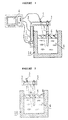
FIG.1 illustrates schematically the structure of an embodiment of the liquid level measuring apparatus of the invention. -
FIG.2 illustrates schematically the structure of another embodiment of the liquid level measuring apparatus of the present invention. - As shown in
FIG.1 , a liquid level measuring apparatus for molten steel comprises animage measuring device 5, a measuringprobe 6, a lifting mechanism 1 adisplacement sensor 11, a data processing system 4 and a correction marker 7 which is a metallic ring fixed to the non-dipping portion of the measuringprobe 6 and is used to correct the change of relative position between theimage measuring device 5 and the measuringprobe 6. The lifting mechanism 1 is fixed to the outer wall of a tundish 10 (a molten steel container) for the continuous casting of the steel. The measuringprobe 6 is vertically hung from thebracket 2 of the lifting mechanism 1 by thefixture 3, and can move up and down with the bracket driven by a motor to be inserted into molten steel 9 or to be raised from it. Thedisplacement sensor 11 is used to measure the raised height of the measuringprobe 6, and fed it back to the data processing system 4. Theimage measuring device 5 is also installed in thebracket 2 of the lifting mechanism 1 and the lifted portion of the measuringprobe 6 from the molten metal 9 and the ring-shaped correction marker 7 are all located within the field of view of theimage measuring device 5. - According to the present invention, the measuring processes of the temperature of liquid steel are as follows:
- The measuring
probe 6 driven by the lifting mechanism 1 moves downwards and inserts vertically into the measured molten steel 9 in thetundish 10 to a predetermined depth through the interface of theslag layer 8 and liquid steel 9, and theimage measuring device 5 captures the images of the surface of theslag layer 8 around the measuringprobe 6. And while the measuringprobe 6 reaches or approaches a thermal equilibrium with the liquid steel 9 and theslag layer 8, the measuringprobe 6 is rapidly elevated and the lifted height is more than the thickness of theslag layer 8, the lifting height is measured by thedisplacement sensor 11 and is transferred to the data processing system 4. At one time, theimage measuring device 5 captures the thermal of the lifted portion of the measuringprobe 6, and then the measuringprobe 6 is afresh inserted into the molten steed 9. The above images are transferred to the data processing system 4 and is processed, analyzed and calculated, and the level heights of the slag-steel interface and the air-slag interface can be determined and then thickness of the layer is obtained. While the measuringprobe 6 is in the state of immerging in the molten steel 9, theimage measuring device 5 can continuously capture the images of the top surface of theslag layer 8 around the measuringprobe 6, and the data processing system can determine the level height of the surface of the slag layer. So the liquid steel level can also be obtained continuously based on the slag surface level and the above obtained thickness of the slag layer or the level heights of said two interfaces. - In this embodiment, the
image measuring device 5 includes a planar array CCD detector and an optical system (not shown), whose optical axis is set at an angle of 21 °46' with the geometric axis of the measuringprobe 6. Theimage measuring device 5 is assembly housed within a cooling jacket and a dust-proof guard is mounted in front end thereof so as to ensure its reliable operating in a severe measuring condition of high temperature and thick dust. - In this embodiment, the
displacement sensor 11 is a tension rod displacement sensor, which installed in the lifting mechanism 1. In another preferred embodiment of the present invention, thedisplacement sensor 11 is a photoelectric encoder-type displacement sensor. - The present embodiment employs the temperature measuring tube for molten steel (as disclosed in China patent No.
00120354.1 ) as the measuringprobe 6 so as to measure the temperature and the level of liquid steel in a tundish, which consists of double bushings having a closed end at one end and an open end at the other, and the inner and the outer bushings are made of alumina-carbon ceramics with a thermal conductivity of 8.7 W/ (m. K) and an outer diameter of 85 mm. - In another preferred embodiment of the present invention, the measuring
probe 6 is made of magnesium-carbon which is in rod shape with a cone shape bottom end, its diameter is 40 mm. - In
embodiment 2 of the present invention, the lifting mechanism 1 is mounted on the lid of the molten metal container such as thetundish 10, which is preferred without the installation conditions in the side wall of the moltern metal container. The measuringdevice 5 is a point-scanning type camera, whose optical axis is set at an angle of 15° with the geometric axis of the measuringprobe 6. The correction marker 7 is an annulation, and it is more than 1 mm but less than 50 mm in thickness and more than 1 mm but less than 100 mm in height. The rest are the same as those in Embodiment 1. - In
embodiment 3 of the present invention, the lifting mechanism 1 is mounted in a suitable position independent of themolten metal container 10, which is preferred without the installation conditions in the molten metal container. Theimage measuring device 5 is a line array-scanning type camera, whose optical axis is set at an angle of 70° with the geometric axis of the measuringprobe 6. The correction marker 7 is a claviform or tubal or lathy object, and it is more than 10 mm but less than 1500 mm in length and more than 2 mm but less than 200 mm in equivalent diameter. The rest are the same as those in embodiment 1. - In embodiment 4 of the present invention, as shown in
FIG 2 , the correction marker 7 is a plumb bob being hung from thebracket 2 of the lifting mechanism 1, and is located within the field of view of theimage measuring device 5. Theimage measuring device 5 is a thermal imager. - In this embodiment, the molten metal 9 is the molten steel, the slag layer is made from slag powder and covering flux, the
metal container 10 is a tundish. The rest are the same as those in embodiment 1. - The beneficial effect of the present invention is: As the invention utilizes a measuring
probe 6 which is inserted into the molten metal 9 through the slag layer, when said measuringprobe 6 is lifted from the molten metal 9, the thermal image displays information relative to the thickness of the slag layer, hence allowing an accurate determination of the thickness of the slag layer and an accurate measurement of the level of the molten metal. - Obviously, numerous modifications and variations of the present invention are possible in light of the above teachings. It is therefore to be understood that within the scope of the appended claims, the present invention may be practiced otherwise than as specifically described herein.
Claims (12)
- An apparatus for measuring the liquid level of molten metal, comprising an image measuring device, a measuring probe, a lifting mechanism, a displacement sensor, a data processing system and a correction marker, wherein:the lifting mechanism is mounted on the molten metal container, or is independent of the molten metal container,the image measuring device is mounted on the lifting mechanism or is independent of the lifting mechanism, the optical axis of the image measuring device is set at an angle with the geometric axis of the measuring probe,the measuring probe is mounted on the lifting mechanism or is independent of the lifting mechanism, the measuring probe is located within the range of the field of view of the image measuring device, andthe image measuring device, the lifting mechanism and the displacement sensor are connected to the data processing system respectively.
- The apparatus for measuring the liquid level of molten metal according to claim 1, characterized in that the lifting mechanism comprises a lifting drive device, a lifting gearing connected to the lifting drive device, a bracket connected to the lifting gearing, and a fixture mounted on the bracket with which the measuring probe is vertically held.
- The apparatus for measuring the liquid level of molten metal according to claim 1, characterized in that the measuring probe is made of refractory materials, such as AL2O3-C, or MgO-C, or AL2O3-C-Zr, or MgO-C-Zr, or of metals with melting point above 800 °C.
- The apparatus for measuring the liquid level of molten metal according to claim 1, characterized in that the measuring probe is the temperature measuring tube which is used synchronously for measuring the temperature and liquid level of molten steel in tundish.
- The apparatus for measuring the liquid level of molten according to claim 1, characterized in that the correction marker is an annulation with more than 1 mm but less than 50 mm in thickness and more than I mm but less than 100 mm in height, or a clubbed or tubular or lathy object with more that 10 mm but less than 1500 mm in length and more than 2 mm but less than 200 mm in equivalent diameter, which is made of refractory materials, such as AL2O3-C, or MgO-C, or AL2O3-C-Zr, or MgO-C-Zr, or of metals with melting point above 500 °C, the correction marker is hung from the bracket of the lifting mechanism, or is fixed to the non-dipping portion of the measuring probe, or is mounted on the cover of molten metal container or inner wall of molten metal container, or in a place independent of the molten metal container and/or the liquid level measuring apparatus where can be recognized and located by the measuring device.
- The apparatus for measuring the liquid level of molten metal according to claim 1, characterized in that the displacement sensor is connected to the lifting mechanism, the displacement sensor is a tension rod, or a pull rope, or a resistance-type, or a photoelectric encoder-type or an image displacement sensor.
- The apparatus for measuring the liquid level of molten metal according to claim 6, characterized in that the optical axis of the image measuring device is set at an angle of 15°-70° with the geometric axis of the measuring probe.
- The apparatus for measuring the liquid level of molten metal according to claim 7, characterized in that the image measuring device can be a line array or a planar (or area) array or a point-scanning type camera, or a thermal imager.
- The apparatus for measuring the liquid level of molten metal according to claim 8, characterized in the image measuring device is assembly housed within a cooling jacket, and the front end of the cooling jacket is equipped with a dust-proof guard.
- A method for measuring the liquid level of molten metal by using the apparatus according to claims 1-9, comprising steps of:(1) the apparatus for measuring the molten metal level is installed on the molten metal container.(2) In operation, the lifting mechanism drives the measuring probe down inserting into a molten metal, when the temperature of measuring probe reaches or approaches a thermal equilibrium with molten metal and layer, the measuring probe is rabidly by the lifting mechanism, the raised height is more than the thickness of the layer, and then the image device captures the thermal of the raised portion of the measuring probe, the thermal are then transferred to the data system by which the original images are processed, analyzed and calculated, and based on the characteristic of having the maximum local temperature at the air-slag interface and the slag-molten metal interface, the level height values of the two interfaces can be acquired by the data processing system.
the difference of the level height values of the two interfaces is just the thickness of the slag layer.(3) It is necessary to determine the relative height of bottom of the molten metal container in the liquid metal level measuring apparatus before operating, which may be obtained by directly measuring the bottom level of the container, or by measuring the descent height of the measuring probe going down to contact with the container bottom, or known in advance.(4) In dipping state of the measuring probe, the image measuring device captures continuously the images at intersection of the slag layer surface and the measuring probe or at intersection of the slag layer surface and the inner wall of the molten metal container, and then the level height of the slag layer surface can be obtained by the data processing system by the image processing, analysis and calculation.(5) Based on the level height of the slag layer surface and the slag layer thickness acquired respectively in the above step (4) and (2), or based on the two interface level heights measured in the above step (2) and the raised height of the measuring probe driven by the lifting mechanism which is measured by the displacement sensor and is input into the data processing system, the liquid level of molten metal could be obtained. - The method for measuring the liquid level of molten metal according to claim 10, characterized in that the optical axis of the image measuring device is set at an angle of 15°-70° with the geometric axis of the measuring probe.
- The method for measuring the liquid level of molten metal according to claim 11, characterized in that the same or separate image measuring devices can be used to measure the thickness of the slag layer described in step (2) and the height of the surface level of the slag layer described in step (4).
Applications Claiming Priority (1)
| Application Number | Priority Date | Filing Date | Title |
|---|---|---|---|
| PCT/CN2008/072856 WO2010048751A1 (en) | 2008-10-28 | 2008-10-28 | Device for measuring level of molten metal and method thereof |
Publications (2)
| Publication Number | Publication Date |
|---|---|
| EP2351997A1 true EP2351997A1 (en) | 2011-08-03 |
| EP2351997A4 EP2351997A4 (en) | 2017-12-27 |
Family
ID=42128181
Family Applications (1)
| Application Number | Title | Priority Date | Filing Date |
|---|---|---|---|
| EP08877654.7A Withdrawn EP2351997A4 (en) | 2008-10-28 | 2008-10-28 | Device for measuring level of molten metal and method thereof |
Country Status (7)
| Country | Link |
|---|---|
| US (1) | US8661891B2 (en) |
| EP (1) | EP2351997A4 (en) |
| KR (1) | KR101254395B1 (en) |
| CN (1) | CN101849167B (en) |
| BR (1) | BRPI0822477B1 (en) |
| RU (1) | RU2473051C2 (en) |
| WO (1) | WO2010048751A1 (en) |
Families Citing this family (45)
| Publication number | Priority date | Publication date | Assignee | Title |
|---|---|---|---|---|
| DE102004032561B3 (en) * | 2004-07-05 | 2006-02-09 | Heraeus Electro-Nite International N.V. | Container for molten metal and use of the container |
| AU2011245743C1 (en) * | 2010-04-30 | 2015-04-23 | Refractory Intellectual Property Gmbh & Co. Kg | Measurements in metallurgical vessels |
| CN102207364B (en) * | 2011-05-11 | 2013-05-22 | 中冶南方工程技术有限公司 | Device and method for measuring thickness distribution of casting powder in crystallizer |
| CN102410827A (en) * | 2011-07-21 | 2012-04-11 | 江苏省沙钢钢铁研究院有限公司 | System and method for automatically measuring the insertion depth of a KR stirring head |
| CN102343428A (en) * | 2011-11-14 | 2012-02-08 | 上海金自天正信息技术有限公司 | Molten steel level automatic control device and method thereof |
| US9228878B2 (en) * | 2012-03-19 | 2016-01-05 | Advanced Energy Industries, Inc. | Dual beam non-contact displacement sensor |
| KR101442630B1 (en) * | 2012-11-07 | 2014-09-19 | 주식회사 포스코 | APPARATUS AND METHOD FOR MEASURING LEVEL IN Zn POT |
| KR101511016B1 (en) * | 2013-09-30 | 2015-04-13 | 주식회사 우진 | apparatus for measuring level of molten iron |
| KR101586389B1 (en) | 2014-09-24 | 2016-02-02 | 주식회사 포스코 | Apparatus for measuring thickness and method for measuring the same |
| KR101704519B1 (en) | 2014-12-23 | 2017-02-08 | 주식회사 포스코 | Apparatus for measuring position of level sensor of molten metal |
| KR101694852B1 (en) * | 2015-12-01 | 2017-01-10 | 한국항공우주연구원 | Apparatus for Measuring Heater Resistance |
| CN105402174B (en) * | 2015-12-08 | 2018-04-03 | 成都飞机设计研究所 | The double remaining detection means and detection determination methods of a kind of hydraulic oil container oil mass |
| CN105728670A (en) * | 2016-04-22 | 2016-07-06 | 中国重型机械研究院股份公司 | Steel ladle liquid level monitoring system and method |
| CN107784644B (en) * | 2016-08-25 | 2019-12-06 | 台州道致科技股份有限公司 | method and device for determining interface of immiscible liquid |
| CN108036834A (en) * | 2018-01-10 | 2018-05-15 | 河北视窗玻璃有限公司 | Glass melter liquid level emasuring device and glass melter level measuring method |
| CN108225484A (en) * | 2018-01-29 | 2018-06-29 | 湖南镭目科技有限公司 | A kind of liquid level detecting system and method |
| CN108414048B (en) * | 2018-03-16 | 2024-01-30 | 中国石油大学(华东) | Liquid level metering device and system of standard metal gauge |
| CN108444391B (en) * | 2018-03-16 | 2024-05-03 | 浙江大学 | Measuring device and measuring method for solid phase suspension height in multiphase transparent stirring kettle |
| CN209157077U (en) * | 2018-04-25 | 2019-07-26 | 西安麦特沃金液控技术有限公司 | Vertical casting crystallization apparatus and vertical continuous casting equipment with liquid storage room |
| EP3567370A1 (en) * | 2018-05-08 | 2019-11-13 | Primetals Technologies Austria GmbH | Lance probe with output of reference voltages |
| CN109186709B (en) * | 2018-09-07 | 2020-10-30 | 北方铜业股份有限公司 | Method for measuring matte liquid level in oxygen-enriched bottom blowing furnace |
| CN110042822B (en) * | 2019-05-27 | 2024-02-06 | 福州大学 | Inclination measuring device and inclination measuring method for measuring multidirectional horizontal displacement of rock and soil body |
| CN112683361B (en) * | 2019-10-19 | 2024-04-12 | 南京晨全机械制造有限公司 | Multi-time measuring mechanism applied to liquid level detection device |
| CN110732660B (en) * | 2019-11-11 | 2024-11-26 | 株洲天桥起重机股份有限公司 | Intelligent zinc ingot quantitative casting device and method |
| CN110726454B (en) * | 2019-11-20 | 2021-06-15 | 青岛澳科仪器有限责任公司 | Material level measuring method and system |
| CN110954440A (en) * | 2019-12-11 | 2020-04-03 | 安徽省锐凌计量器制造有限公司 | Density liquid level detection device and detection method |
| CN111421120B (en) * | 2020-04-14 | 2024-08-02 | 石家庄钢铁有限责任公司 | Device and method for calibrating molten steel level of crystallizer of bloom continuous casting machine |
| KR102356466B1 (en) * | 2020-06-17 | 2022-01-27 | (재)대구기계부품연구원 | Apparatus for integrated testing wear resistancy and thermal stress |
| CN112033493A (en) * | 2020-08-11 | 2020-12-04 | 东北大学 | Continuous casting molten pool liquid level detection system and continuous casting molten pool liquid level control method |
| CN112050768B (en) * | 2020-08-31 | 2023-03-24 | 钢铁研究总院 | Automatic slag layer thickness measuring device and method |
| US11692883B2 (en) | 2020-10-28 | 2023-07-04 | Advanced Energy Industries, Inc. | Fiber optic temperature probe |
| KR102362990B1 (en) * | 2020-11-06 | 2022-02-15 | 동국제강주식회사 | Measurement apparatus of molten metal volume and measurement method of molten metal volume using the same |
| CN112461329A (en) * | 2020-11-16 | 2021-03-09 | 上海修悟机械设备有限公司 | Device and method for measuring liquid level of tundish by using robot |
| KR102263588B1 (en) * | 2020-11-24 | 2021-06-10 | 싸이엔스 주식회사 | Method and apparatus for measuring slag thickness using artificial neural network |
| CN113090938B (en) * | 2021-03-25 | 2022-03-25 | 中南大学湘雅医院 | Medical liquid nitrogen storage device |
| CN113333700B (en) * | 2021-06-30 | 2023-01-06 | 广东韶钢松山股份有限公司 | Casting and pouring method for automatically inspecting liquid level of crystallizer |
| CN113418565A (en) * | 2021-07-20 | 2021-09-21 | 光大环保技术研究院(深圳)有限公司 | Device and method for measuring temperature and slag thickness in plasma melting furnace |
| EP4184131B1 (en) * | 2021-11-19 | 2025-09-03 | Airbus S.A.S. | Optical level gauge apparatus and method, liquid tank assembly and vehicle employing the same |
| CN116475392A (en) * | 2022-01-17 | 2023-07-25 | 宝山钢铁股份有限公司 | Device for measuring liquid level of molten steel in continuous casting tundish and using method thereof |
| CN114951563B (en) * | 2022-05-31 | 2023-09-26 | 新余钢铁股份有限公司 | Continuous casting immersion nozzle insertion depth measuring device and application method thereof |
| CN115752329A (en) * | 2022-11-23 | 2023-03-07 | 广州虹科电子科技有限公司 | Metallurgical slag copper surface inspection ruler analysis system and method |
| CN116428863A (en) * | 2023-03-28 | 2023-07-14 | 中国恩菲工程技术有限公司 | Metallurgical slag layer thickness detection device, metallurgical furnace system and metallurgical slag layer thickness detection method |
| CN116875816B (en) * | 2023-06-13 | 2025-07-25 | 石河子众和新材料有限公司 | High-purity aluminum production system |
| CN117647295B (en) * | 2024-01-30 | 2024-05-14 | 合肥金星智控科技股份有限公司 | Machine vision-based molten pool liquid level measurement method, electronic equipment and storage medium |
| CN120425164B (en) * | 2025-05-27 | 2026-03-17 | 湖南省汨罗锦胜智造科技股份有限公司 | A method for separating and recycling lead sludge from lead-acid batteries |
Family Cites Families (18)
| Publication number | Priority date | Publication date | Assignee | Title |
|---|---|---|---|---|
| SU392233A1 (en) * | 1967-06-13 | 1973-07-27 | DEVICE FOR REGISTRATION OF DEPTHS WHEN CARRYING | |
| AT297073B (en) * | 1969-04-15 | 1972-03-10 | Voest Ag | Method for measuring the thickness of the slag layer on metallic baths, in particular on melts to be degassed by vacuum treatment |
| US3717034A (en) * | 1971-02-12 | 1973-02-20 | Steel Corp | Apparatus for immersing and withdrawing bath examination means into and from a molten bath |
| DE2945251A1 (en) | 1979-11-09 | 1981-05-14 | Betriebsforschungsinstitut VDEh - Institut für angewandte Forschung GmbH, 4000 Düsseldorf | Measuring level of liq. steel in ladles etc. - using laser beam directed at surface at angle to axis of imaging system |
| JPS6362812A (en) * | 1986-09-01 | 1988-03-19 | Nippon Kokan Kk <Nkk> | Detector for slag foaming in converter |
| JPS63196820A (en) * | 1987-02-10 | 1988-08-15 | Nippon Steel Corp | Method and apparatus for measuring level and temperature of molten metal |
| FR2667003A1 (en) * | 1990-09-21 | 1992-03-27 | Siderurgie Fse Inst Rech | METHOD AND DEVICE FOR CONTINUOUSLY MEASURING THE THICKNESS OF LIQUID DAIRY. |
| GB9022496D0 (en) * | 1990-10-17 | 1990-11-28 | British Steel Plc | Measurement of the temperature of a melt |
| JPH11108736A (en) * | 1997-09-30 | 1999-04-23 | Sumitomo Metal Ind Ltd | How to measure the weight of molten metal in a container |
| RU2146039C1 (en) * | 1997-11-26 | 2000-02-27 | ОАО "Нижнетагильский металлургический комбинат" | Object position measurement technique |
| KR100406371B1 (en) * | 1998-12-24 | 2004-01-24 | 주식회사 우진 | Apparatus and method for detecting thickness of slag layer in ladle |
| CN1116593C (en) * | 2000-07-12 | 2003-07-30 | 东北大学 | Method for continuous measuring molten steel temperature and temp. measuring tube |
| JP5124894B2 (en) * | 2001-05-25 | 2013-01-23 | ヘレウス・エレクトロナイト株式会社 | Slag layer thickness or slag layer thickness and molten metal layer surface level position measuring method and apparatus |
| TW562866B (en) * | 2001-07-27 | 2003-11-21 | Nippon Steel Corp | Temperature measuring apparatus and method for molten metal |
| JP2003041328A (en) * | 2001-08-02 | 2003-02-13 | Mitsui Mining & Smelting Co Ltd | Matt smelting furnace solution level measurement method |
| TW579392B (en) * | 2001-12-31 | 2004-03-11 | China Steel Corp | Method and device for detecting liquid level and slag location in smelter |
| JP2006112954A (en) * | 2004-10-15 | 2006-04-27 | Toyota Motor Corp | Molten metal level measuring device and molten metal level measuring method |
| RU54944U1 (en) * | 2006-01-10 | 2006-07-27 | Открытое акционерное общество "Магнитогорский металлургический комбинат" | DEVICE FOR MEASURING THE METAL LEVEL IN THE CONVERTER |
-
2008
- 2008-10-28 EP EP08877654.7A patent/EP2351997A4/en not_active Withdrawn
- 2008-10-28 BR BRPI0822477 patent/BRPI0822477B1/en not_active IP Right Cessation
- 2008-10-28 KR KR1020107029609A patent/KR101254395B1/en not_active Expired - Fee Related
- 2008-10-28 RU RU2010149978/28A patent/RU2473051C2/en not_active IP Right Cessation
- 2008-10-28 WO PCT/CN2008/072856 patent/WO2010048751A1/en not_active Ceased
- 2008-10-28 CN CN2008800032293A patent/CN101849167B/en not_active Expired - Fee Related
- 2008-10-28 US US12/994,410 patent/US8661891B2/en not_active Expired - Fee Related
Non-Patent Citations (1)
| Title |
|---|
| See references of WO2010048751A1 * |
Also Published As
| Publication number | Publication date |
|---|---|
| BRPI0822477A2 (en) | 2015-06-16 |
| RU2010149978A (en) | 2012-06-20 |
| KR20110013541A (en) | 2011-02-09 |
| US8661891B2 (en) | 2014-03-04 |
| CN101849167B (en) | 2011-06-01 |
| US20110063628A1 (en) | 2011-03-17 |
| CN101849167A (en) | 2010-09-29 |
| RU2473051C2 (en) | 2013-01-20 |
| EP2351997A4 (en) | 2017-12-27 |
| KR101254395B1 (en) | 2013-04-12 |
| BRPI0822477A8 (en) | 2019-10-22 |
| WO2010048751A1 (en) | 2010-05-06 |
| BRPI0822477B1 (en) | 2019-12-10 |
Similar Documents
| Publication | Publication Date | Title |
|---|---|---|
| US8661891B2 (en) | Apparatus and method for measuring the liquid level of molten metal | |
| JP5878166B2 (en) | Measurement in metallurgical vessel | |
| EP2924442B1 (en) | Device and method for continuously measuring flow rate near liquid steel surface | |
| CN110631709A (en) | A non-contact molten steel temperature detection method for converter steelmaking | |
| TR201900736T4 (en) | Method and apparatus for determining the consumption of electrode material during electric arc furnace operation. | |
| CN110595419A (en) | System and method for measuring thickness of liquid slag layer of casting powder | |
| He et al. | A novel principle for molten steel level measurement in tundish by using temperature gradient | |
| ZA200505377B (en) | Container for molten metal, use of the container and method for determining an interface layer | |
| JP4277681B2 (en) | Melt surface position detection device for single crystal pulling device and single crystal pulling device | |
| CN219776333U (en) | Metallurgical slag layer thickness detection device and metallurgical furnace system | |
| CN115041642B (en) | Tapping method of converter | |
| EP0080965B1 (en) | Method and apparatus for carrying out a measuring or sampling operation in a molten metal bath | |
| JP5375815B2 (en) | Method for controlling immersion depth of probe for measuring molten metal, and probe for measuring molten metal used therefor | |
| JP4947044B2 (en) | Melt surface position detection device for single crystal pulling device and single crystal pulling device | |
| JPH08168860A (en) | Measuring method of molten steel level in mold | |
| Hu et al. | Molten steel level measuring method by thermal image analysis in tundish | |
| JP3215532B2 (en) | Measuring method of molten metal weight | |
| JPH0599640A (en) | Method for diagnosing refractories for steelmaking | |
| CN116428863A (en) | Metallurgical slag layer thickness detection device, metallurgical furnace system and metallurgical slag layer thickness detection method | |
| JP2004301362A (en) | Metal surface level measurement method in hot metal ladle desulfurization equipment | |
| CN113252133A (en) | Method for measuring molten iron liquid level height of molten iron tank | |
| JPH07236958A (en) | Level control device for continuous casting equipment | |
| JPS58115291A (en) | Detector for state of breaking due to melting of refractory of molten-metal vessel | |
| JPH02251362A (en) | Method and instrument for detecting flowing-out of slag | |
| JPH0579967A (en) | Spherical body lift type viscosity measuring method and device thereof |
Legal Events
| Date | Code | Title | Description |
|---|---|---|---|
| PUAI | Public reference made under article 153(3) epc to a published international application that has entered the european phase |
Free format text: ORIGINAL CODE: 0009012 |
|
| 17P | Request for examination filed |
Effective date: 20110527 |
|
| AK | Designated contracting states |
Kind code of ref document: A1 Designated state(s): AT BE BG CH CY CZ DE DK EE ES FI FR GB GR HR HU IE IS IT LI LT LU LV MC MT NL NO PL PT RO SE SI SK TR |
|
| DAX | Request for extension of the european patent (deleted) | ||
| RA4 | Supplementary search report drawn up and despatched (corrected) |
Effective date: 20171129 |
|
| RIC1 | Information provided on ipc code assigned before grant |
Ipc: G01F 23/292 20060101ALN20171123BHEP Ipc: G01F 23/00 20060101AFI20171123BHEP Ipc: G01F 23/22 20060101ALI20171123BHEP Ipc: G01F 23/04 20060101ALN20171123BHEP Ipc: B22D 2/00 20060101ALI20171123BHEP |
|
| STAA | Information on the status of an ep patent application or granted ep patent |
Free format text: STATUS: EXAMINATION IS IN PROGRESS |
|
| 17Q | First examination report despatched |
Effective date: 20191126 |
|
| STAA | Information on the status of an ep patent application or granted ep patent |
Free format text: STATUS: THE APPLICATION IS DEEMED TO BE WITHDRAWN |
|
| 18D | Application deemed to be withdrawn |
Effective date: 20210112 |