EP2349950B1 - Honeycomb structural body for exhaust gas purification - Google Patents
Honeycomb structural body for exhaust gas purification Download PDFInfo
- Publication number
- EP2349950B1 EP2349950B1 EP08876062.4A EP08876062A EP2349950B1 EP 2349950 B1 EP2349950 B1 EP 2349950B1 EP 08876062 A EP08876062 A EP 08876062A EP 2349950 B1 EP2349950 B1 EP 2349950B1
- Authority
- EP
- European Patent Office
- Prior art keywords
- honeycomb
- structural body
- honeycomb structural
- silicon carbide
- segments
- Prior art date
- Legal status (The legal status is an assumption and is not a legal conclusion. Google has not performed a legal analysis and makes no representation as to the accuracy of the status listed.)
- Active
Links
Images

Classifications
-
- C—CHEMISTRY; METALLURGY
- C04—CEMENTS; CONCRETE; ARTIFICIAL STONE; CERAMICS; REFRACTORIES
- C04B—LIME, MAGNESIA; SLAG; CEMENTS; COMPOSITIONS THEREOF, e.g. MORTARS, CONCRETE OR LIKE BUILDING MATERIALS; ARTIFICIAL STONE; CERAMICS; REFRACTORIES; TREATMENT OF NATURAL STONE
- C04B38/00—Porous mortars, concrete, artificial stone or ceramic ware; Preparation thereof
- C04B38/0006—Honeycomb structures
- C04B38/0016—Honeycomb structures assembled from subunits
- C04B38/0019—Honeycomb structures assembled from subunits characterised by the material used for joining separate subunits
-
- B—PERFORMING OPERATIONS; TRANSPORTING
- B01—PHYSICAL OR CHEMICAL PROCESSES OR APPARATUS IN GENERAL
- B01D—SEPARATION
- B01D46/00—Filters or filtering processes specially modified for separating dispersed particles from gases or vapours
- B01D46/24—Particle separators, e.g. dust precipitators, using rigid hollow filter bodies
- B01D46/2403—Particle separators, e.g. dust precipitators, using rigid hollow filter bodies characterised by the physical shape or structure of the filtering element
- B01D46/2418—Honeycomb filters
-
- B—PERFORMING OPERATIONS; TRANSPORTING
- B32—LAYERED PRODUCTS
- B32B—LAYERED PRODUCTS, i.e. PRODUCTS BUILT-UP OF STRATA OF FLAT OR NON-FLAT, e.g. CELLULAR OR HONEYCOMB, FORM
- B32B37/00—Methods or apparatus for laminating, e.g. by curing or by ultrasonic bonding
- B32B37/14—Methods or apparatus for laminating, e.g. by curing or by ultrasonic bonding characterised by the properties of the layers
- B32B37/146—Methods or apparatus for laminating, e.g. by curing or by ultrasonic bonding characterised by the properties of the layers whereby one or more of the layers is a honeycomb structure
-
- B—PERFORMING OPERATIONS; TRANSPORTING
- B32—LAYERED PRODUCTS
- B32B—LAYERED PRODUCTS, i.e. PRODUCTS BUILT-UP OF STRATA OF FLAT OR NON-FLAT, e.g. CELLULAR OR HONEYCOMB, FORM
- B32B37/00—Methods or apparatus for laminating, e.g. by curing or by ultrasonic bonding
- B32B37/14—Methods or apparatus for laminating, e.g. by curing or by ultrasonic bonding characterised by the properties of the layers
- B32B37/16—Methods or apparatus for laminating, e.g. by curing or by ultrasonic bonding characterised by the properties of the layers with all layers existing as coherent layers before laminating
- B32B37/18—Methods or apparatus for laminating, e.g. by curing or by ultrasonic bonding characterised by the properties of the layers with all layers existing as coherent layers before laminating involving the assembly of discrete sheets or panels only
-
- C—CHEMISTRY; METALLURGY
- C04—CEMENTS; CONCRETE; ARTIFICIAL STONE; CERAMICS; REFRACTORIES
- C04B—LIME, MAGNESIA; SLAG; CEMENTS; COMPOSITIONS THEREOF, e.g. MORTARS, CONCRETE OR LIKE BUILDING MATERIALS; ARTIFICIAL STONE; CERAMICS; REFRACTORIES; TREATMENT OF NATURAL STONE
- C04B28/00—Compositions of mortars, concrete or artificial stone, containing inorganic binders or the reaction product of an inorganic and an organic binder, e.g. polycarboxylate cements
- C04B28/24—Compositions of mortars, concrete or artificial stone, containing inorganic binders or the reaction product of an inorganic and an organic binder, e.g. polycarboxylate cements containing alkyl, ammonium or metal silicates; containing silica sols
-
- C—CHEMISTRY; METALLURGY
- C04—CEMENTS; CONCRETE; ARTIFICIAL STONE; CERAMICS; REFRACTORIES
- C04B—LIME, MAGNESIA; SLAG; CEMENTS; COMPOSITIONS THEREOF, e.g. MORTARS, CONCRETE OR LIKE BUILDING MATERIALS; ARTIFICIAL STONE; CERAMICS; REFRACTORIES; TREATMENT OF NATURAL STONE
- C04B35/00—Shaped ceramic products characterised by their composition; Ceramics compositions; Processing powders of inorganic compounds preparatory to the manufacturing of ceramic products
- C04B35/515—Shaped ceramic products characterised by their composition; Ceramics compositions; Processing powders of inorganic compounds preparatory to the manufacturing of ceramic products based on non-oxide ceramics
- C04B35/56—Shaped ceramic products characterised by their composition; Ceramics compositions; Processing powders of inorganic compounds preparatory to the manufacturing of ceramic products based on non-oxide ceramics based on carbides or oxycarbides
- C04B35/565—Shaped ceramic products characterised by their composition; Ceramics compositions; Processing powders of inorganic compounds preparatory to the manufacturing of ceramic products based on non-oxide ceramics based on carbides or oxycarbides based on silicon carbide
-
- C—CHEMISTRY; METALLURGY
- C04—CEMENTS; CONCRETE; ARTIFICIAL STONE; CERAMICS; REFRACTORIES
- C04B—LIME, MAGNESIA; SLAG; CEMENTS; COMPOSITIONS THEREOF, e.g. MORTARS, CONCRETE OR LIKE BUILDING MATERIALS; ARTIFICIAL STONE; CERAMICS; REFRACTORIES; TREATMENT OF NATURAL STONE
- C04B37/00—Joining burned ceramic articles with other burned ceramic articles or other articles by heating
- C04B37/003—Joining burned ceramic articles with other burned ceramic articles or other articles by heating by means of an interlayer consisting of a combination of materials selected from glass, or ceramic material with metals, metal oxides or metal salts
- C04B37/005—Joining burned ceramic articles with other burned ceramic articles or other articles by heating by means of an interlayer consisting of a combination of materials selected from glass, or ceramic material with metals, metal oxides or metal salts consisting of glass or ceramic material
-
- C—CHEMISTRY; METALLURGY
- C04—CEMENTS; CONCRETE; ARTIFICIAL STONE; CERAMICS; REFRACTORIES
- C04B—LIME, MAGNESIA; SLAG; CEMENTS; COMPOSITIONS THEREOF, e.g. MORTARS, CONCRETE OR LIKE BUILDING MATERIALS; ARTIFICIAL STONE; CERAMICS; REFRACTORIES; TREATMENT OF NATURAL STONE
- C04B38/00—Porous mortars, concrete, artificial stone or ceramic ware; Preparation thereof
- C04B38/0006—Honeycomb structures
-
- F—MECHANICAL ENGINEERING; LIGHTING; HEATING; WEAPONS; BLASTING
- F01—MACHINES OR ENGINES IN GENERAL; ENGINE PLANTS IN GENERAL; STEAM ENGINES
- F01N—GAS-FLOW SILENCERS OR EXHAUST APPARATUS FOR MACHINES OR ENGINES IN GENERAL; GAS-FLOW SILENCERS OR EXHAUST APPARATUS FOR INTERNAL-COMBUSTION ENGINES
- F01N3/00—Exhaust or silencing apparatus having means for purifying, rendering innocuous, or otherwise treating exhaust
- F01N3/02—Exhaust or silencing apparatus having means for purifying, rendering innocuous, or otherwise treating exhaust for cooling, or for removing solid constituents of, exhaust
- F01N3/021—Exhaust or silencing apparatus having means for purifying, rendering innocuous, or otherwise treating exhaust for cooling, or for removing solid constituents of, exhaust by means of filters
- F01N3/022—Exhaust or silencing apparatus having means for purifying, rendering innocuous, or otherwise treating exhaust for cooling, or for removing solid constituents of, exhaust by means of filters characterised by specially adapted filtering structure, e.g. honeycomb, mesh or fibrous
- F01N3/0222—Exhaust or silencing apparatus having means for purifying, rendering innocuous, or otherwise treating exhaust for cooling, or for removing solid constituents of, exhaust by means of filters characterised by specially adapted filtering structure, e.g. honeycomb, mesh or fibrous the structure being monolithic, e.g. honeycombs
-
- C—CHEMISTRY; METALLURGY
- C04—CEMENTS; CONCRETE; ARTIFICIAL STONE; CERAMICS; REFRACTORIES
- C04B—LIME, MAGNESIA; SLAG; CEMENTS; COMPOSITIONS THEREOF, e.g. MORTARS, CONCRETE OR LIKE BUILDING MATERIALS; ARTIFICIAL STONE; CERAMICS; REFRACTORIES; TREATMENT OF NATURAL STONE
- C04B2235/00—Aspects relating to ceramic starting mixtures or sintered ceramic products
- C04B2235/02—Composition of constituents of the starting material or of secondary phases of the final product
- C04B2235/30—Constituents and secondary phases not being of a fibrous nature
- C04B2235/34—Non-metal oxides, non-metal mixed oxides, or salts thereof that form the non-metal oxides upon heating, e.g. carbonates, nitrates, (oxy)hydroxides, chlorides
- C04B2235/3418—Silicon oxide, silicic acids or oxide forming salts thereof, e.g. silica sol, fused silica, silica fume, cristobalite, quartz or flint
-
- C—CHEMISTRY; METALLURGY
- C04—CEMENTS; CONCRETE; ARTIFICIAL STONE; CERAMICS; REFRACTORIES
- C04B—LIME, MAGNESIA; SLAG; CEMENTS; COMPOSITIONS THEREOF, e.g. MORTARS, CONCRETE OR LIKE BUILDING MATERIALS; ARTIFICIAL STONE; CERAMICS; REFRACTORIES; TREATMENT OF NATURAL STONE
- C04B2235/00—Aspects relating to ceramic starting mixtures or sintered ceramic products
- C04B2235/02—Composition of constituents of the starting material or of secondary phases of the final product
- C04B2235/50—Constituents or additives of the starting mixture chosen for their shape or used because of their shape or their physical appearance
- C04B2235/52—Constituents or additives characterised by their shapes
- C04B2235/5208—Fibers
- C04B2235/5216—Inorganic
- C04B2235/522—Oxidic
- C04B2235/5232—Silica or silicates other than aluminosilicates, e.g. quartz
-
- C—CHEMISTRY; METALLURGY
- C04—CEMENTS; CONCRETE; ARTIFICIAL STONE; CERAMICS; REFRACTORIES
- C04B—LIME, MAGNESIA; SLAG; CEMENTS; COMPOSITIONS THEREOF, e.g. MORTARS, CONCRETE OR LIKE BUILDING MATERIALS; ARTIFICIAL STONE; CERAMICS; REFRACTORIES; TREATMENT OF NATURAL STONE
- C04B2235/00—Aspects relating to ceramic starting mixtures or sintered ceramic products
- C04B2235/02—Composition of constituents of the starting material or of secondary phases of the final product
- C04B2235/50—Constituents or additives of the starting mixture chosen for their shape or used because of their shape or their physical appearance
- C04B2235/52—Constituents or additives characterised by their shapes
- C04B2235/5208—Fibers
- C04B2235/526—Fibers characterised by the length of the fibers
-
- C—CHEMISTRY; METALLURGY
- C04—CEMENTS; CONCRETE; ARTIFICIAL STONE; CERAMICS; REFRACTORIES
- C04B—LIME, MAGNESIA; SLAG; CEMENTS; COMPOSITIONS THEREOF, e.g. MORTARS, CONCRETE OR LIKE BUILDING MATERIALS; ARTIFICIAL STONE; CERAMICS; REFRACTORIES; TREATMENT OF NATURAL STONE
- C04B2235/00—Aspects relating to ceramic starting mixtures or sintered ceramic products
- C04B2235/02—Composition of constituents of the starting material or of secondary phases of the final product
- C04B2235/50—Constituents or additives of the starting mixture chosen for their shape or used because of their shape or their physical appearance
- C04B2235/52—Constituents or additives characterised by their shapes
- C04B2235/5208—Fibers
- C04B2235/5264—Fibers characterised by the diameter of the fibers
-
- C—CHEMISTRY; METALLURGY
- C04—CEMENTS; CONCRETE; ARTIFICIAL STONE; CERAMICS; REFRACTORIES
- C04B—LIME, MAGNESIA; SLAG; CEMENTS; COMPOSITIONS THEREOF, e.g. MORTARS, CONCRETE OR LIKE BUILDING MATERIALS; ARTIFICIAL STONE; CERAMICS; REFRACTORIES; TREATMENT OF NATURAL STONE
- C04B2235/00—Aspects relating to ceramic starting mixtures or sintered ceramic products
- C04B2235/02—Composition of constituents of the starting material or of secondary phases of the final product
- C04B2235/50—Constituents or additives of the starting mixture chosen for their shape or used because of their shape or their physical appearance
- C04B2235/54—Particle size related information
- C04B2235/5418—Particle size related information expressed by the size of the particles or aggregates thereof
- C04B2235/5436—Particle size related information expressed by the size of the particles or aggregates thereof micrometer sized, i.e. from 1 to 100 micron
-
- C—CHEMISTRY; METALLURGY
- C04—CEMENTS; CONCRETE; ARTIFICIAL STONE; CERAMICS; REFRACTORIES
- C04B—LIME, MAGNESIA; SLAG; CEMENTS; COMPOSITIONS THEREOF, e.g. MORTARS, CONCRETE OR LIKE BUILDING MATERIALS; ARTIFICIAL STONE; CERAMICS; REFRACTORIES; TREATMENT OF NATURAL STONE
- C04B2235/00—Aspects relating to ceramic starting mixtures or sintered ceramic products
- C04B2235/02—Composition of constituents of the starting material or of secondary phases of the final product
- C04B2235/50—Constituents or additives of the starting mixture chosen for their shape or used because of their shape or their physical appearance
- C04B2235/54—Particle size related information
- C04B2235/5418—Particle size related information expressed by the size of the particles or aggregates thereof
- C04B2235/5445—Particle size related information expressed by the size of the particles or aggregates thereof submicron sized, i.e. from 0,1 to 1 micron
-
- C—CHEMISTRY; METALLURGY
- C04—CEMENTS; CONCRETE; ARTIFICIAL STONE; CERAMICS; REFRACTORIES
- C04B—LIME, MAGNESIA; SLAG; CEMENTS; COMPOSITIONS THEREOF, e.g. MORTARS, CONCRETE OR LIKE BUILDING MATERIALS; ARTIFICIAL STONE; CERAMICS; REFRACTORIES; TREATMENT OF NATURAL STONE
- C04B2235/00—Aspects relating to ceramic starting mixtures or sintered ceramic products
- C04B2235/02—Composition of constituents of the starting material or of secondary phases of the final product
- C04B2235/50—Constituents or additives of the starting mixture chosen for their shape or used because of their shape or their physical appearance
- C04B2235/54—Particle size related information
- C04B2235/5463—Particle size distributions
- C04B2235/5472—Bimodal, multi-modal or multi-fraction
-
- C—CHEMISTRY; METALLURGY
- C04—CEMENTS; CONCRETE; ARTIFICIAL STONE; CERAMICS; REFRACTORIES
- C04B—LIME, MAGNESIA; SLAG; CEMENTS; COMPOSITIONS THEREOF, e.g. MORTARS, CONCRETE OR LIKE BUILDING MATERIALS; ARTIFICIAL STONE; CERAMICS; REFRACTORIES; TREATMENT OF NATURAL STONE
- C04B2237/00—Aspects relating to ceramic laminates or to joining of ceramic articles with other articles by heating
- C04B2237/02—Aspects relating to interlayers, e.g. used to join ceramic articles with other articles by heating
- C04B2237/04—Ceramic interlayers
- C04B2237/08—Non-oxidic interlayers
- C04B2237/083—Carbide interlayers, e.g. silicon carbide interlayers
-
- C—CHEMISTRY; METALLURGY
- C04—CEMENTS; CONCRETE; ARTIFICIAL STONE; CERAMICS; REFRACTORIES
- C04B—LIME, MAGNESIA; SLAG; CEMENTS; COMPOSITIONS THEREOF, e.g. MORTARS, CONCRETE OR LIKE BUILDING MATERIALS; ARTIFICIAL STONE; CERAMICS; REFRACTORIES; TREATMENT OF NATURAL STONE
- C04B2237/00—Aspects relating to ceramic laminates or to joining of ceramic articles with other articles by heating
- C04B2237/30—Composition of layers of ceramic laminates or of ceramic or metallic articles to be joined by heating, e.g. Si substrates
- C04B2237/32—Ceramic
- C04B2237/36—Non-oxidic
- C04B2237/365—Silicon carbide
-
- Y—GENERAL TAGGING OF NEW TECHNOLOGICAL DEVELOPMENTS; GENERAL TAGGING OF CROSS-SECTIONAL TECHNOLOGIES SPANNING OVER SEVERAL SECTIONS OF THE IPC; TECHNICAL SUBJECTS COVERED BY FORMER USPC CROSS-REFERENCE ART COLLECTIONS [XRACs] AND DIGESTS
- Y10—TECHNICAL SUBJECTS COVERED BY FORMER USPC
- Y10S—TECHNICAL SUBJECTS COVERED BY FORMER USPC CROSS-REFERENCE ART COLLECTIONS [XRACs] AND DIGESTS
- Y10S502/00—Catalyst, solid sorbent, or support therefor: product or process of making
- Y10S502/52712—Plural layers on a support, each layer having a distinct function
-
- Y—GENERAL TAGGING OF NEW TECHNOLOGICAL DEVELOPMENTS; GENERAL TAGGING OF CROSS-SECTIONAL TECHNOLOGIES SPANNING OVER SEVERAL SECTIONS OF THE IPC; TECHNICAL SUBJECTS COVERED BY FORMER USPC CROSS-REFERENCE ART COLLECTIONS [XRACs] AND DIGESTS
- Y10—TECHNICAL SUBJECTS COVERED BY FORMER USPC
- Y10S—TECHNICAL SUBJECTS COVERED BY FORMER USPC CROSS-REFERENCE ART COLLECTIONS [XRACs] AND DIGESTS
- Y10S502/00—Catalyst, solid sorbent, or support therefor: product or process of making
- Y10S502/52714—Specified support particles of peculiar structure or physical form, e.g. whiskers, fiber pieces
- Y10S502/52715—Layered deposition on support particle, i.e. on a carrier particle
-
- Y—GENERAL TAGGING OF NEW TECHNOLOGICAL DEVELOPMENTS; GENERAL TAGGING OF CROSS-SECTIONAL TECHNOLOGIES SPANNING OVER SEVERAL SECTIONS OF THE IPC; TECHNICAL SUBJECTS COVERED BY FORMER USPC CROSS-REFERENCE ART COLLECTIONS [XRACs] AND DIGESTS
- Y10—TECHNICAL SUBJECTS COVERED BY FORMER USPC
- Y10S—TECHNICAL SUBJECTS COVERED BY FORMER USPC CROSS-REFERENCE ART COLLECTIONS [XRACs] AND DIGESTS
- Y10S502/00—Catalyst, solid sorbent, or support therefor: product or process of making
- Y10S502/52714—Specified support particles of peculiar structure or physical form, e.g. whiskers, fiber pieces
- Y10S502/52716—Specified shape of support particle, e.g. hollow-carrier particle
-
- Y—GENERAL TAGGING OF NEW TECHNOLOGICAL DEVELOPMENTS; GENERAL TAGGING OF CROSS-SECTIONAL TECHNOLOGIES SPANNING OVER SEVERAL SECTIONS OF THE IPC; TECHNICAL SUBJECTS COVERED BY FORMER USPC CROSS-REFERENCE ART COLLECTIONS [XRACs] AND DIGESTS
- Y10—TECHNICAL SUBJECTS COVERED BY FORMER USPC
- Y10S—TECHNICAL SUBJECTS COVERED BY FORMER USPC CROSS-REFERENCE ART COLLECTIONS [XRACs] AND DIGESTS
- Y10S502/00—Catalyst, solid sorbent, or support therefor: product or process of making
- Y10S502/52719—Monolith with specified shape or dimension of cell opening, e.g. honeycomb, rings
-
- Y—GENERAL TAGGING OF NEW TECHNOLOGICAL DEVELOPMENTS; GENERAL TAGGING OF CROSS-SECTIONAL TECHNOLOGIES SPANNING OVER SEVERAL SECTIONS OF THE IPC; TECHNICAL SUBJECTS COVERED BY FORMER USPC CROSS-REFERENCE ART COLLECTIONS [XRACs] AND DIGESTS
- Y10—TECHNICAL SUBJECTS COVERED BY FORMER USPC
- Y10T—TECHNICAL SUBJECTS COVERED BY FORMER US CLASSIFICATION
- Y10T156/00—Adhesive bonding and miscellaneous chemical manufacture
- Y10T156/10—Methods of surface bonding and/or assembly therefor
Definitions
- the present invention relates to a method of manufacturing a structural body, comprising honeycomb segments and a sealing material layer, and to a honeycomb structural body obtainable by said method suitable for use in a particulate filter of exhaust gas emitted by a vehicle.
- exhaust gas it is intended a flue gas that is produced as a result of the combustion of fuels, such gasoline/petrol, diesel, fuel oil or coal.
- PM particulate matter
- an exhaust gas such as the exhaust gas produced by a diesel engine
- the main fraction of PM is composed of very small particles, mainly consisting of impure carbon particles (in jargon, also referred to as “soot”). Because of their small size, said particles, when inhaled, may easily penetrate deep into the lungs. The rough surfaces of these particles make it easy for them to bind with other toxins in the environment, thus increasing the hazards of particle inhalation.
- the discharge amount of PM becomes large in a diesel engine using a gas oil as a fuel or a direct-injection type gasoline engine recently coming into wide use.
- a solution for removing (or at least reducing) the PM emissions of an exhaust gas produced by fuel combustion, e.g., in a vehicle engine, provides for the use of a particulate filter.
- a particulate filter - in this case, referred to as Diesel Particulate Filter (DPF) - is a device arranged in an exhaust gas emission path of the diesel engine for receiving the exhaust gas and retain the PM included thereinto.
- a conventional DPF may consist of a cylindrical body made of porous material, such as silicon carbide (SiC), with a first base (upstream side) receiving the flow of the exhaust gas produced by the engine.
- Such DPF has a honeycomb structure, with a plurality of exhaust gas flowing channels extending in parallel to the longitudinal direction of the cylindrical body, from the upstream side body to a downstream side, corresponding to a second base of the cylindrical opposite to the first one. These channels are alternatively plugged at either the upstream side or the downstream side to form a checker pattern.
- the exhaust gas (including PM) hits the first surface, and is forced to flow through the channels of the DPF that are not plugged at the upstream side. Thanks to the porosity properties of the SiC, the PM included in the exhaust gas is blocked by the walls of said channels, and remain confined in the DPF, while the rest of the exhaust gas (essentially free of PM) crosses the walls, passes into the adjacent channels and exits from the DPF, for being outputted outside the vehicle through exhaust pipes.
- honeycomb structural body used in the exhaust gas converting apparatus for vehicles there is well known a one-piece type honeycomb structure (called as a honeycomb monolith) made of a low thermal expansive cordierite.
- This type of the honeycomb structural body is used by carrying a material having a high specific surface area such as active alumina or the like, a catalyst of a noble metal such as platinum or the like, and an alkali metal for the NOx converting treatment on the wall surface.
- honeycomb structural body there is also known an aggregate type honeycomb structural body formed by integrally bonding a plurality of honeycomb structural units (honeycomb segments) comprising a silicon carbide material prepared by extrusion molding.
- JP07-054643 discloses an exhaust emission control device manufactured by combining and arranging twelve pieces of filters formed into a honeycomb shape by a porous silicon carbide sintered body.
- a seal member serving as a heat resistant filling material is interposed between the filters adjacent to each other, and its periphery is covered by a heat insulating member.
- the seal member is comprised of a ceramic fiber, a silicon carbide powder, and an inorganic binder.
- EP 816065 discloses a ceramic structure in which a plurality of the ceramic members are integrally adhered by interposing a sealing member of an elastic material consisting of inorganic fibers, preferably a ceramic fiber, an inorganic binder, preferably a colloidal sol, an organic binder, preferably a polysaccharide, and inorganic particles, preferably inorganic powder or whisker selected from a carbide and a nitride, and mutually bonded three-dimensionally intersected organic fibers and inorganic particles through the inorganic binder and organic binder between the mutual ceramic members.
- the ceramic fiber is selected from silica-alumina, mullite, alumina and silica
- the colloidal sol is selected from silica sol and alumina sol
- the polysaccharide is selected from polyvinyl alcohol, methyl cellulose, ethyl cellulose and carboxymethyl cellulose
- the inorganic powder or whisker is selected from silicon carbide, silicon nitride and boron nitride.
- the sealing member consists of silica-alumina ceramic fiber, silica sol, carboxymethyl cellulose and silicon carbide powder.
- US 6,777,114 discloses that when a silicon carbide-based honeycomb filter having a structure bonded by metallic silicon is used as a DPF and then is reactivated, oxidation reactions under a low oxygen partial pressure may take place causing the destruction of the filter caused by sharp temperature increase due to the oxidation of, in particular, metallic silicon.
- Further metallic silicon has a property of easily dissolving in an acid when having no oxide film thereon.
- a sintered body containing metallic silicon as a constituent is used as a DPF, the sintered body is exposed to an acidic gas atmosphere generated by the combustion of sulfur, etc. present in the fuel used; and there has been a fear of, for example, the destruction of the filter caused by dissolution of metallic silicon. Therefore, the formation of an oxygen-containing phase at the surface of the silicon carbide particles and/or the metallic silicon or in the vicinity of the surface is suggested to suppress the oxidative decomposition of the silicon carbide and the metallic silicon.
- SiC as a Substrate for Diesel Particulate Filters
- SAE Technical Paper Series 932495 1993 discloses that one possible concern of the use of SiC as diesel filter may be that of high temperature corrosion.
- the oxidation can reach a depth of about 0.05 ⁇ m and this corresponds to a reduction of the contact area (SiC-SiC) between the sintered grains of approximately 0.2%, and at 1500°C, the reduction of the contact area can be about 1%, so that for extreme temperature excursions, the layer can crack and therefore allow local free passage of oxygen to the SiC, and a consequent increase in the rate of oxidation.
- EP1707546A1 and EP1997789A1 disclose joining SiC honeycomb segments with sealing materials.
- the Applicant has faced the problem of providing a honeycomb structural body, particularly suited for a diesel particulate filter, comprising honeycomb segments bonded together with the aid of a sealing material, having a high bonding strength, an excellent durability, and a high resistance to thermal stress that is exerted on the honeycomb structural body during regenerating processes and operations.
- an oxidation layer formed on the outer walls of silicon carbide honeycomb segments can significantly improve the bonding of the segments in the honeycomb structural body.
- a honeycomb structural body being excellent in the bonding strength and thermal shock resistance at the joint portion of the honeycomb segments and capable of maintaining a good durability for a long time, can be obtained by forming an oxidation layer on the outer walls of silicon carbide honeycomb segments and by performing the bonding of the thus obtained oxidized segments with the aid of a sealing material consisting of a mixture of one or more silicon carbide powder, one or more ceramic fiber, and one or more inorganic binder, water, and in the absence of organic binders.
- a sealing material consisting of a mixture of one or more silicon carbide powder, one or more ceramic fiber, and one or more inorganic binder, water, and in the absence of organic binders.
- the invention relates to a method for the manufacturing of a honeycomb structural body as defined in claim 1.
- the invention in a second aspect, relates to a honeycomb structural body comprising a plurality of honeycomb segments as defined in claim 9.
- the step of providing a plurality of silicon carbide honeycomb segments comprises mixing one or more silicon carbide powder, one or more organic binder, one or more dispersing agent and one or more solvent to form a starting paste.
- the formed starting paste may be advantageously extruded to form a green honeycomb structure.
- the formed green honeycomb structure may then be advantageously sintered at a temperature of from 1,500° to 3,000°C under an oxygen-free atmosphere. More preferably, the green honeycomb structure is dried to remove solvent(s). Still more preferably the green honeycomb structure is debinded to remove organic compound(s).
- the step of subjecting said honeycomb segments to an oxidizing thermal treatment forming a surface layer of silicon oxides on said at least one outer wall may be performed by thermal treating the honeycomb segments in an oxygen-containing atmosphere at a temperature ranging from 500° to 1,400°.
- the thermal treatment is performed from 600° to 1,300°C. More preferably, the thermal treatment is performed from 700° to 1,200°.
- the thermal treatment can be performed for a period of time of from 1 to 15 hours. More preferably the thermal treatment is performed from 1 to 10 hours.
- the Applicant has found that when the thermal treatment temperature and time is specified as above, an optimal thickness of the layer of silicon oxides is formed on the outer walls of the honeycomb segment(s).
- the layer of silicon oxides has a thickness of from 0.001 ⁇ m to 10 ⁇ m.
- the silicon oxides may comprise amorphous or crystalline SiO 2 , or SiO, or a mixture thereof.
- the Applicant has found that owing to the presence of an oxidation layer on the outer walls of the honeycomb segment and/or in the vicinity of the outer walls, the adhesion properties of the honeycomb segment can be significantly improved.
- the step of bonding the plurality of oxidized honeycomb segments comprises applying a sealing layer on at least one outer wall of a honeycomb segment. At least two outer walls of said honeycomb segments are advantageously joined so as to interpose said sealing layer. The joined honeycomb segments are then typically cured.
- the honeycomb structural body preferably comprises from 2 to 10 honeycomb segments. More preferably, the honeycomb structural body comprises from 4 to 8 honeycomb segments.
- a coating layer can be further applied onto the outer peripheral portion of the honeycomb structural body.
- the coating layer is preferable for protecting the outer peripheral portion of the honeycomb structural body and increasing its strength.
- the sealing material has a viscosity value lower than 200 Pa.s (pascal per second). More preferably, the sealing material has a viscosity value in the range of from 100 to 180 Pa.s.
- the sealing material comprises from about 20% to about 80% by weight of silicon carbide powder.
- the amount of ceramic fiber in the sealing material is preferably comprised from about 5% to about 50% by weight.
- the amount of inorganic binder in the sealing material is preferably comprised from about 1% to about 20% by weight.
- the silicon carbide powder has an average particle diameter lower than 10 ⁇ m.
- the ceramic fiber is selected from alkali and alkaline earth silicate fibers.
- the inorganic binder is selected from alumina sol, silica sol, titania sol, water glass and mixture thereof.
- the sealing material having the composition as described above provides to the honeycomb structural body an excellent durability and a high resistance to thermal stress.
- said sealing layer has a thickness of about 0.1 to 8 mm.
- a starting paste mainly composed of one or more silicon carbide powder, one or more organic binder, one or more dispersing agent and one or more solvent is prepared.
- the silicon carbide powder has an average particle diameter lower than 100 ⁇ m. More preferably, the silicon carbide powder is a mixture of at least one silicon carbide powder having a high average particle diameter, i.e. from 10 to 100 ⁇ m, and at least one silicon carbide powder having a low average particle diameter, i.e. from 10 to 0.01 ⁇ m. Most preferably, the silicon carbide powder is a mixture of a silicon carbide powder having an average particle diameter ranging from 25 to 75 ⁇ m and a silicon carbide powder having an average particle diameter ranging from 1 to 0.1 ⁇ m.
- organic binder may be used, for example, one or more organic binders selected from methylcellulose, carboxymethyl cellulose, hydroxyethyl cellulose, polyethylene glycol, phenolic resin and epoxy resin.
- the amount of the organic binder is preferably 1 to 10 parts by weight based on 100 parts by weight of the total amount of silicon carbide powder.
- the dispersing agent may be used, for example, ethylene glycol, dextrin, aliphatic acid, aliphatic acid soap, polyvinyl alcohol, polyethylene glycol and the like.
- the amount of the dispersing agent is preferably 1 to 10 parts by weight based on 100 parts by weight of the total amount of silicon carbide powder.
- solvent for example, water, organic solvent (benzene or the like), alcohol and so on.
- the starting paste is preferably well mixed and kneaded.
- it may be mixed by using a mixer, or sufficiently kneaded by means of a kneader or the like.
- the starting paste is extrusion-molded to form a green honeycomb structure having through-holes, for example, by means of the extrusion molding.
- the green honeycomb structure can be preferably extruded with a predefined shape, for example, a polygonal shape, a cylinder shape, a circular sector shape, a circular corona sector shape, and the like.
- the resulting green honeycomb structure is cut to the desired length in order to give the green honeycomb segment, which is subsequently dried.
- a drying machine used for the drying may be used, for example, a microwave drying machine, a hot-air drying machine, a dielectric drying machine, a reduced-pressure drying machine, a vacuum drying machine, a freeze drying machine and the like.
- the dried green honeycomb segment is subjected to the debinding for the removal of organic compounds.
- the condition for the debinding is properly adjusted according to the kind or amount of the organic matter contained in the green honeycomb segment, but a condition of, for example, approximately 400°C for 2 hours is preferable.
- the dried and degreased green honeycomb segment is sintered.
- the sintering is conducted, for example, at a temperature of from 1,500 to 3,000°C, preferably from 2,000°C to 2,500°C, and most preferably of about 2400°C.
- the sintering time ranges from 1 to 10 hours, and preferably from 1 to 5 hours.
- the sintering is conducted in an atmosphere substantially free of oxygen, for example, under argon atmosphere.
- the sintered honeycomb segment is subjected to a thermal treatment in the presence of oxygen.
- the thermal treatment in an oxygen-containing atmosphere is carried out preferably at a temperature ranging from 500 to 1,400°C., more preferably from 600 to 1,300°C., further preferably at 700 to 1,200°C.
- the thermal treatment is conducted for a period of time of from 1 to 15 hours, preferably from 1 to 10 hours.
- the silicon oxides constituting the surface layer may preferably be amorphous and/or crystalline SiO 2 , SiO, or a mixture thereof, more preferably, amorphous and/or crystalline SiO 2 .
- the surface layer of silicon oxides has preferably a thickness of from 0.001 to 10 ⁇ m, more preferably from 0.1 to 10 ⁇ m, and most preferably from 1 to 10 ⁇ m.
- the Applicant has found that owing to the presence of an oxidation layer on the outer walls of the honeycomb segment and/or in the vicinity of the outer walls, the adhesion properties of the honeycomb segment can be significantly improved.
- a sealing material paste forming a sealing layer is applied onto the oxidized outer walls of the obtained honeycomb segments, whereby the honeycomb segments are joined with each other and then dried to form a bonded honeycomb structural body having the desired shape and size.
- the sealing material consists of a mixture of at least one silicon carbide powder, at least one ceramic fiber, water and at least one inorganic binder. No organic binders are used in the sealing material.
- the silicon carbide powder there is no particular limitation about the silicon carbide powder, and any silicon carbide powder can be used in the manufacturing of the sealing material.
- the silicon carbide powder has an average particle diameter lower than 10 ⁇ m, more preferably lower than 5 ⁇ m, and most preferably lower than 1 ⁇ m.
- the silicon carbide powder is present in an amount of from about 20% to about 80% by weight and preferably from about 30% to about 60% by weight of the sealing material.
- the ceramic fibers used in the present invention are alkali and alkaline earth silicate fibers. Suitable ceramic fibers usually have diameters of from about 0.5 to about 20 ⁇ m and lengths of from about 0.5 to about 50 mm. Other ceramic fibers which can be used include basalt rock wool and fiberglass.
- the ceramic fiber is present in an amount of from about 5% to about 50% and preferably from about 10% to about 30% by weight of the sealing material.
- the inorganic binder may be used, for example, an inorganic colloidal solution.
- inorganic colloidal solution comprise, for example, one or more inorganic colloidal solution selected from alumina sol, silica sol, titania sol, water glass and the like.
- colloidal silica used in accordance with the present invention can be essentially any colloidal silica; however, the most desirable colloidal silicas are those which have the smaller average particle size and which can be easily dispersed.
- the inorganic binder is present in an amount of from about 1 to about 20 percent and preferably from about 5 to about 10 percent by weight of the sealing material.
- the sealing material has a viscosity value lower than 200 Pa.s (pascal per second), preferably in the range of from 100 to 180 Pa.s at 25°C, when measured with a Bohlin rheometer shear rate 1s -1 , rotor plate-plate 40 mm diameter and gap of 1,500/2,000 micron.
- These viscosity values imply that the sealing material has an improved fluidity and wettability on the surface of the honeycomb segments. This results in an improved interface interaction between the surface of the honeycomb segments and the surface of the sealing material, which results in an increased interpenetration of the sealing material and an increased adhesion strength.
- the sealing layer formed for joining the honeycomb segments with each other preferably has a thickness of about 0.1 to 8 mm.
- the thickness is less than 0.1 mm, there is a fear that a sufficient bonding strength is not obtained.
- the thickness of the sealing material layer exceeds 8 mm, it has a portion not functioning as an exhaust gas conversion, so that the specific surface area per unit volume of the honeycomb structural body lowers and the catalyst component can not be sufficiently dispersed.
- the number of the bonded honeycomb segments is properly determined in accordance with the size of the honeycomb structural body.
- the number of the bonded honeycomb segments is not higher than twelve.
- the number of the bonded honeycomb segments ranges from 2 to 10, more preferably from 4 to 8.
- a sealing material may be applied onto the outer peripheral portion of the honeycomb structural body or the side surface thereof not opening the through-holes .
- the sealing material may be dried to form a coating layer for the purpose of the gas sealing.
- the coating layer is preferable for protecting the outer peripheral portion of the honeycomb structural body and increasing its strength.
- the coating material is not particularly limited, but may be made of the same material as the above sealing material or a different material.
- the coating material may have the same compounding ratio as in the sealing material layer or a different compounding ratio.
- the thickness of the coating material layer is preferably approximately 0.1 to 2 mm. When the thickness is less than 0.1 mm, the protection of the outer peripheral surface becomes insufficient and the strength can not be enhanced. While, when it exceeds 2 mm, the specific surface area per unit volume as a honeycomb structural body lowers.
- the joined structure is cured.
- the curing of the structure is preferably conducted under a condition of about 800°C for 1 hour, though the conditions may vary according to the kind or amount of the included organic matter.
- honeycomb structural bodies shown in Figs. 1 to 4 are examples of the invention, but the invention is not limited only thereto.
- a man skilled in the art can easily conceive other shapes for the honeycomb structural body, for example, rectangular shape or elliptical shape, as well as other shapes for the honeycomb segments employed to realize the structural body.
- honeycomb structural bodies 1a, 1b shown in Figs. 1 to 4 comprise a plurality of honeycomb segments 2 each having a cell structure 3 comprising cells 4 and cell walls 5. These cells 4 are alternatively plugged at either the upstream side or the downstream side to form a checker pattern.
- Each honeycomb segment 2 comprises outer walls 6 bonded each other by the interposition of a sealing layer 7 and peripheral walls 8, optionally covered by a coating layer 9.
- the thickness (wall thickness) of the cell wall is not particularly limited, but is preferably about 0.05 to 1 mm.
- the wall thickness is less than 0.05 mm, the strength of the porous honeycomb body lowers, while when it exceeds 1 mm, the exhaust gas does not sufficiently penetrate into the interior of the wall and does not contact with the catalyst carried in the interior of the wall, and hence the catalytic action lowers.
- the thickness of the cell wall is preferably approximately 0.10 to 0.80 mm, more preferably 0.15 to 0.60 mm.
- the number of the through-holes per unit cross sectional area is preferably approximately 15.5 to 186 holes/cm 2 (100 to 1200 cpsi).
- the number of the through-holes is preferably approximately 46.5 to 170.5 holes/cm 2 (300 to 1100 cpsi), more preferably approximately 62.0 to 155 holes/cm 2 (400 to 1000 cpsi).
- the cross sectional shape of the cell formed on the honeycomb segment is preferably polygonal, for example, triangle, quadrilateral (square), rectangular, trapezoidal, pentagonal, hexagonal, octagonal and the like, or may be of various polygons.
- the cross section may be approximately triangle or hexagon. In this case, it is considered to enhance the strength of the porous honeycomb unit to increase the strength of the honeycomb structural body (e.g. isostatic strength or the like) without lowering the pressure loss, exhaust gas conversion capability and the like.
- the honeycomb structural body according to the invention may be used in the form of a honeycomb catalyst obtained by carrying a catalyst component in the cell walls (on the surfaces of the particles) or on the surfaces of the cell walls.
- a catalyst component for example, a noble metal, an alkali metal compound, an alkaline earth metal compound, an oxide and the like may be used as catalyst component.
- One or more metals selected from platinum, palladium, and rhodium may be used as noble metal.
- As the alkali metal compound for example, one or more compounds selected from potassium, sodium and the like may be used.
- As the alkaline earth metal compound for example, a compound of barium or the like may be used.
- perovskite La 0.75 K 0.25 MnO 3
- CeO 2 or the like may be used.
- Such a honeycomb catalyst can be used, for example, as a so-called three-way catalyst, or NOx absorption catalyst for the conversion of the exhaust gas discharged from automobiles.
- the catalyst component may be carried on the surfaces of the cell walls after the production of the honeycomb structural body, or on the surface of the each ceramic particle as the starting material in the production of the honeycomb units.
- the carrying of the catalyst component can be conducted, for example, by the impregnation method or the like.
- a mixed composition is prepared by mixing for 30 minutes under dry conditions in a vessel equipped with a rotating mixer 63 parts by weight of silicon carbide particles having average particle diameter of about 60 ⁇ m, 12 parts by weight of silicon carbide particles having average particle diameter of about 0.5 ⁇ m, 5 parts by weight of methylcellulose, and 1.25 parts by weight of a fatty acid (Lipestrol EOG). Then, a solution of polyethylene glycol (PEG 400) in water was added and the resulting paste was mixed for about 30 minutes.
- PEG 400 polyethylene glycol
- the resulting paste was extrusion-molded by means of an extruder to obtain a green honeycomb segment having a rectangular shape and with a cell density of about 180 cpsi (cells per square inch).
- the green honeycomb segment was cut at the proper length and sufficiently dried by using a microwave drying machine and a hot-air drying machine and debinded to remove organic residuals by holding at 500°C for 1 hour.
- the green honeycomb segment was sintered under argon atmosphere at about 2,000° - 2400°C for about 2 hours to obtain a sample of a honeycomb segment A made of porous silicon carbide.
- honeycomb segment A was thermally treated under normal atmosphere at 850° - 1150°C for about 1 hour to form the surface layer of silicon oxides and to give the honeycomb segment B.
- a paste for a sealing material was prepared by mixing 44 parts by weight of silicon carbide powder having average particle diameter of 0.5 ⁇ m, 20 parts by weight of ceramic fibers (alkaline earth silicate fibers) having an average fiber diameter of 3-5 micron and an average fiber length of 600 micron, about 7 parts by weight of colloidal silica, and about 29 parts by weight of water, which was used as paste 1.
- the viscosity of the sealing material was 120 Pa.s (measured with a Bohlin rheometer at 25°C, shear rate 1s -1 , rotor plate-plate 40 mm diameter and gap of 1,500/2,000 ⁇ m).
- Another paste for a sealing material was prepared by mixing 30 parts by weight of silicon carbide powder having average particle diameter of 0.5 ⁇ m, 25 parts by weight of short ceramic fibers (alkaline earth silicate fibers) having an average fiber diameter of 3-5 micron and an average fiber length of 600 micron, 3 parts by weight of long ceramic fibers (alkaline earth silicate fibers) having an average fiber diameter of 3-5 micron and an average fiber length of 1500 micron, about 7 parts by weight of colloidal silica, about 0.5 parts by weight of cellulose based organic binder, and about 35 parts by weight of water, which was used as paste 2.
- the viscosity of the sealing material was 230 Pa.s (measured with a Bohlin rheometer, at 25°C, shear rate 1s -1 , rotor plate-plate 40mm diameter and GAP: 1500/2000 ⁇ m).
- honeycomb segments A having a rectangular shape (6x3.5x1cm) were joined along the longer lateral face with paste 1 by forming a sealing layer having a thickness of about 2 mm, drying at 90°C for three hours and sintering at 800°C for one hour. The procedure was repeated by using two honeycomb segments B having the same shape and by replacing paste 1 with paste 2.
- the coefficient of thermal expansion (CTE) was measured with a heating speed of 5°C/min starting from room temperature and until to 800°C under an air flux of 500 ml/min.
- the CTE of the sintered paste 1 was compared with the CTE of the honeycomb segment.
- the resulting graphics were almost identical, with a nonlinear expansion until to 160°C, and a linear expansion in the range of from 160°C to 800°C.
- the average CTE ( ⁇ ) of the sintered paste 1 in the range 160° - 750°C was 4.20 x 10 -6
- the average CTE of the honeycomb segment in the range 26° - 620°C was 4.61 x 10 -6 .
- the low difference of CTE allows to obtain a better resistance to thermal stress exerted during regenerating processes and operations on the honeycomb filter and a longer durability of the honeycomb filter.
Landscapes
- Chemical & Material Sciences (AREA)
- Engineering & Computer Science (AREA)
- Ceramic Engineering (AREA)
- Materials Engineering (AREA)
- Structural Engineering (AREA)
- Organic Chemistry (AREA)
- Chemical Kinetics & Catalysis (AREA)
- Manufacturing & Machinery (AREA)
- Inorganic Chemistry (AREA)
- Physics & Mathematics (AREA)
- Geometry (AREA)
- Combustion & Propulsion (AREA)
- Mechanical Engineering (AREA)
- General Engineering & Computer Science (AREA)
- Filtering Materials (AREA)
- Catalysts (AREA)
- Civil Engineering (AREA)
- Thermal Sciences (AREA)
Description
- The present invention relates to a method of manufacturing a structural body, comprising honeycomb segments and a sealing material layer, and to a honeycomb structural body obtainable by said method suitable for use in a particulate filter of exhaust gas emitted by a vehicle.
- With the term "exhaust gas" it is intended a flue gas that is produced as a result of the combustion of fuels, such gasoline/petrol, diesel, fuel oil or coal. The ever increasing diffusion of power plants, industrial process plants, and motor vehicles in the world, has urgently led to the study of possible solutions for reducing the harmful effects of the exhaust gases on the environment and on the man.
- Indeed, although the largest part of most exhaust gases is relatively harmless nitrogen, water vapor (exception made for pure-carbon fuels), and carbon dioxide (with the exception of hydrogen as fuel), a relatively small part thereof is formed by undesirable toxic substances, such as carbon monoxide, hydrocarbons, nitrogen oxides, partly unburned fuel, and particulate matter.
- Generally speaking, with the term "particulate matter" (briefly referred to as "PM") it is intended solid or liquid particles suspended in a gas. In an exhaust gas, such as the exhaust gas produced by a diesel engine, the main fraction of PM is composed of very small particles, mainly consisting of impure carbon particles (in jargon, also referred to as "soot"). Because of their small size, said particles, when inhaled, may easily penetrate deep into the lungs. The rough surfaces of these particles make it easy for them to bind with other toxins in the environment, thus increasing the hazards of particle inhalation. The discharge amount of PM becomes large in a diesel engine using a gas oil as a fuel or a direct-injection type gasoline engine recently coming into wide use.
- A solution for removing (or at least reducing) the PM emissions of an exhaust gas produced by fuel combustion, e.g., in a vehicle engine, provides for the use of a particulate filter. Making reference to the exhaust gas produced by a diesel engine, a particulate filter - in this case, referred to as Diesel Particulate Filter (DPF) - is a device arranged in an exhaust gas emission path of the diesel engine for receiving the exhaust gas and retain the PM included thereinto.
- A conventional DPF may consist of a cylindrical body made of porous material, such as silicon carbide (SiC), with a first base (upstream side) receiving the flow of the exhaust gas produced by the engine. Such DPF has a honeycomb structure, with a plurality of exhaust gas flowing channels extending in parallel to the longitudinal direction of the cylindrical body, from the upstream side body to a downstream side, corresponding to a second base of the cylindrical opposite to the first one. These channels are alternatively plugged at either the upstream side or the downstream side to form a checker pattern.
- The exhaust gas (including PM) hits the first surface, and is forced to flow through the channels of the DPF that are not plugged at the upstream side. Thanks to the porosity properties of the SiC, the PM included in the exhaust gas is blocked by the walls of said channels, and remain confined in the DPF, while the rest of the exhaust gas (essentially free of PM) crosses the walls, passes into the adjacent channels and exits from the DPF, for being outputted outside the vehicle through exhaust pipes.
- Heretofore, as the honeycomb structural body used in the exhaust gas converting apparatus for vehicles, there is well known a one-piece type honeycomb structure (called as a honeycomb monolith) made of a low thermal expansive cordierite. This type of the honeycomb structural body is used by carrying a material having a high specific surface area such as active alumina or the like, a catalyst of a noble metal such as platinum or the like, and an alkali metal for the NOx converting treatment on the wall surface.
- As another example of the honeycomb structural body, there is also known an aggregate type honeycomb structural body formed by integrally bonding a plurality of honeycomb structural units (honeycomb segments) comprising a silicon carbide material prepared by extrusion molding.
-
JP07-054643 -
EP 816065 -
US 6,777,114 discloses that when a silicon carbide-based honeycomb filter having a structure bonded by metallic silicon is used as a DPF and then is reactivated, oxidation reactions under a low oxygen partial pressure may take place causing the destruction of the filter caused by sharp temperature increase due to the oxidation of, in particular, metallic silicon. Further metallic silicon has a property of easily dissolving in an acid when having no oxide film thereon. As a result, when a sintered body containing metallic silicon as a constituent is used as a DPF, the sintered body is exposed to an acidic gas atmosphere generated by the combustion of sulfur, etc. present in the fuel used; and there has been a fear of, for example, the destruction of the filter caused by dissolution of metallic silicon. Therefore, the formation of an oxygen-containing phase at the surface of the silicon carbide particles and/or the metallic silicon or in the vicinity of the surface is suggested to suppress the oxidative decomposition of the silicon carbide and the metallic silicon. - P. Stobbe et al, "SiC as a Substrate for Diesel Particulate Filters", SAE Technical Paper Series 932495, 1993 discloses that one possible concern of the use of SiC as diesel filter may be that of high temperature corrosion. The authors explain that silicon carbide oxidizes relatively easily in connection with atmospheric air according to reaction (I), thereby forming a tight layer of amorphous silica on the surface of the material.
SiC + 2O2 → SiO2 + CO2 (I)
- The reference also discloses that at 900°C, the oxidation can reach a depth of about 0.05 µm and this corresponds to a reduction of the contact area (SiC-SiC) between the sintered grains of approximately 0.2%, and at 1500°C, the reduction of the contact area can be about 1%, so that for extreme temperature excursions, the layer can crack and therefore allow local free passage of oxygen to the SiC, and a consequent increase in the rate of oxidation.
EP1707546A1 andEP1997789A1 disclose joining SiC honeycomb segments with sealing materials. - The Applicant has faced the problem of providing a honeycomb structural body, particularly suited for a diesel particulate filter, comprising honeycomb segments bonded together with the aid of a sealing material, having a high bonding strength, an excellent durability, and a high resistance to thermal stress that is exerted on the honeycomb structural body during regenerating processes and operations.
- Contrarily to the disadvantages reported in the above cited documents, the Applicant has unexpectedly found that an oxidation layer formed on the outer walls of silicon carbide honeycomb segments can significantly improve the bonding of the segments in the honeycomb structural body.
- More particularly, the Applicant has unexpectedly found that a honeycomb structural body, being excellent in the bonding strength and thermal shock resistance at the joint portion of the honeycomb segments and capable of maintaining a good durability for a long time, can be obtained by forming an oxidation layer on the outer walls of silicon carbide honeycomb segments and by performing the bonding of the thus obtained oxidized segments with the aid of a sealing material consisting of a mixture of one or more silicon carbide powder, one or more ceramic fiber, and one or more inorganic binder, water, and in the absence of organic binders. In particular, it has been surprisingly found that the cooperation between the above mentioned sealing material and the oxidation layer allows obtaining a significantly increased bonding strength in the bonded honeycomb structural body.
- In a first aspect, the invention relates to a method for the manufacturing of a honeycomb structural body as defined in claim 1.
- In a second aspect, the invention relates to a honeycomb structural body comprising a plurality of honeycomb segments as defined in
claim 9. - Preferably, the step of providing a plurality of silicon carbide honeycomb segments comprises mixing one or more silicon carbide powder, one or more organic binder, one or more dispersing agent and one or more solvent to form a starting paste. The formed starting paste may be advantageously extruded to form a green honeycomb structure. The formed green honeycomb structure may then be advantageously sintered at a temperature of from 1,500° to 3,000°C under an oxygen-free atmosphere. More preferably, the green honeycomb structure is dried to remove solvent(s). Still more preferably the green honeycomb structure is debinded to remove organic compound(s).
- Advantageously, the step of subjecting said honeycomb segments to an oxidizing thermal treatment forming a surface layer of silicon oxides on said at least one outer wall may be performed by thermal treating the honeycomb segments in an oxygen-containing atmosphere at a temperature ranging from 500° to 1,400°. Preferably, the thermal treatment is performed from 600° to 1,300°C. More preferably, the thermal treatment is performed from 700° to 1,200°. The thermal treatment can be performed for a period of time of from 1 to 15 hours. More preferably the thermal treatment is performed from 1 to 10 hours.
- The Applicant has found that when the thermal treatment temperature and time is specified as above, an optimal thickness of the layer of silicon oxides is formed on the outer walls of the honeycomb segment(s).
- Preferably, the layer of silicon oxides has a thickness of from 0.001 µm to 10 µm. In preferred embodiments, the silicon oxides may comprise amorphous or crystalline SiO2, or SiO, or a mixture thereof.
- The Applicant has found that owing to the presence of an oxidation layer on the outer walls of the honeycomb segment and/or in the vicinity of the outer walls, the adhesion properties of the honeycomb segment can be significantly improved.
- The step of bonding the plurality of oxidized honeycomb segments comprises applying a sealing layer on at least one outer wall of a honeycomb segment. At least two outer walls of said honeycomb segments are advantageously joined so as to interpose said sealing layer. The joined honeycomb segments are then typically cured.
- Particularly, the honeycomb structural body preferably comprises from 2 to 10 honeycomb segments. More preferably, the honeycomb structural body comprises from 4 to 8 honeycomb segments.
- Advantageously, a coating layer can be further applied onto the outer peripheral portion of the honeycomb structural body.
- The Applicant has found that the coating layer is preferable for protecting the outer peripheral portion of the honeycomb structural body and increasing its strength.
- The sealing material has a viscosity value lower than 200 Pa.s (pascal per second). More preferably, the sealing material has a viscosity value in the range of from 100 to 180 Pa.s.
- The Applicant has observed that these viscosity values imply that the sealing material has an improved fluidity and wettability on the surface of the honeycomb segments. The Applicant believes that this improves the interface interaction between the surface of the oxidized honeycomb segments and the surface of the sealing material, which results in an increased interpenetration of the sealing material and an increased adhesion strength.
- In preferred embodiments, the sealing material comprises from about 20% to about 80% by weight of silicon carbide powder. The amount of ceramic fiber in the sealing material is preferably comprised from about 5% to about 50% by weight. The amount of inorganic binder in the sealing material is preferably comprised from about 1% to about 20% by weight.
- Preferably, the silicon carbide powder has an average particle diameter lower than 10 µm.
- The ceramic fiber is selected from alkali and alkaline earth silicate fibers.
- Preferably, the inorganic binder is selected from alumina sol, silica sol, titania sol, water glass and mixture thereof.
- The Applicant has found that the sealing material having the composition as described above provides to the honeycomb structural body an excellent durability and a high resistance to thermal stress.
- Preferably, said sealing layer has a thickness of about 0.1 to 8 mm.
- Further features and advantages will become more apparent from the detailed description which follows. This description will be set out hereinafter with reference to the accompanying drawings, given by way of non-limiting example, in which:
-
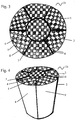
Fig. 1 is a top-view of a cylindrical honeycomb structural body according to an embodiment of the present invention comprising four honeycomb segments; -
Fig. 2 is a diagrammatic perspective view of the honeycomb structural body ofFigure 1 ; -
Fig. 3 is a top-view of a cylindrical honeycomb structural body according to a further embodiment of the present invention comprising seven honeycomb segments; -
Fig. 4 is a diagrammatic perspective view of the honeycomb structural body ofFigure 3 . - An example of a production method of the honeycomb structural body and of a honeycomb structural body according to the invention will be described below.
- Firstly, in order to provide honeycomb segments for the honeycomb structural body a starting paste mainly composed of one or more silicon carbide powder, one or more organic binder, one or more dispersing agent and one or more solvent is prepared.
- There is no particular limitation about the silicon carbide powder, and any silicon carbide powder can be used in the manufacturing of the starting paste. Preferably, the silicon carbide powder has an average particle diameter lower than 100 µm. More preferably, the silicon carbide powder is a mixture of at least one silicon carbide powder having a high average particle diameter, i.e. from 10 to 100 µm, and at least one silicon carbide powder having a low average particle diameter, i.e. from 10 to 0.01 µm. Most preferably, the silicon carbide powder is a mixture of a silicon carbide powder having an average particle diameter ranging from 25 to 75 µm and a silicon carbide powder having an average particle diameter ranging from 1 to 0.1 µm.
- As the organic binder may be used, for example, one or more organic binders selected from methylcellulose, carboxymethyl cellulose, hydroxyethyl cellulose, polyethylene glycol, phenolic resin and epoxy resin. The amount of the organic binder is preferably 1 to 10 parts by weight based on 100 parts by weight of the total amount of silicon carbide powder.
- As the dispersing agent may be used, for example, ethylene glycol, dextrin, aliphatic acid, aliphatic acid soap, polyvinyl alcohol, polyethylene glycol and the like. The amount of the dispersing agent is preferably 1 to 10 parts by weight based on 100 parts by weight of the total amount of silicon carbide powder.
- As the solvent may be used, for example, water, organic solvent (benzene or the like), alcohol and so on.
- The starting paste is preferably well mixed and kneaded. For example, it may be mixed by using a mixer, or sufficiently kneaded by means of a kneader or the like. The starting paste is extrusion-molded to form a green honeycomb structure having through-holes, for example, by means of the extrusion molding. The green honeycomb structure can be preferably extruded with a predefined shape, for example, a polygonal shape, a cylinder shape, a circular sector shape, a circular corona sector shape, and the like.
- Next, the resulting green honeycomb structure is cut to the desired length in order to give the green honeycomb segment, which is subsequently dried. As a drying machine used for the drying may be used, for example, a microwave drying machine, a hot-air drying machine, a dielectric drying machine, a reduced-pressure drying machine, a vacuum drying machine, a freeze drying machine and the like.
- Then, the dried green honeycomb segment is subjected to the debinding for the removal of organic compounds. The condition for the debinding is properly adjusted according to the kind or amount of the organic matter contained in the green honeycomb segment, but a condition of, for example, approximately 400°C for 2 hours is preferable.
- After that, the dried and degreased green honeycomb segment is sintered. The sintering is conducted, for example, at a temperature of from 1,500 to 3,000°C, preferably from 2,000°C to 2,500°C, and most preferably of about 2400°C. The sintering time ranges from 1 to 10 hours, and preferably from 1 to 5 hours. The sintering is conducted in an atmosphere substantially free of oxygen, for example, under argon atmosphere.
- Finally, the sintered honeycomb segment is subjected to a thermal treatment in the presence of oxygen. The thermal treatment in an oxygen-containing atmosphere is carried out preferably at a temperature ranging from 500 to 1,400°C., more preferably from 600 to 1,300°C., further preferably at 700 to 1,200°C. The thermal treatment is conducted for a period of time of from 1 to 15 hours, preferably from 1 to 10 hours. Thus, according to the process of the present invention, particularly wherein the thermal treatment temperature and time is specified as above, a layer of silicon oxides is effectively formed on the outer walls of the honeycomb segment.
- In the honeycomb segment used in the present invention, the silicon oxides constituting the surface layer may preferably be amorphous and/or crystalline SiO2, SiO, or a mixture thereof, more preferably, amorphous and/or crystalline SiO2. The surface layer of silicon oxides has preferably a thickness of from 0.001 to 10 µm, more preferably from 0.1 to 10 µm, and most preferably from 1 to 10 µm.
- The Applicant has found that owing to the presence of an oxidation layer on the outer walls of the honeycomb segment and/or in the vicinity of the outer walls, the adhesion properties of the honeycomb segment can be significantly improved.
- Then, a sealing material paste forming a sealing layer is applied onto the oxidized outer walls of the obtained honeycomb segments, whereby the honeycomb segments are joined with each other and then dried to form a bonded honeycomb structural body having the desired shape and size.
- The sealing material consists of a mixture of at least one silicon carbide powder, at least one ceramic fiber, water and at least one inorganic binder. No organic binders are used in the sealing material.
- There is no particular limitation about the silicon carbide powder, and any silicon carbide powder can be used in the manufacturing of the sealing material. Preferably, the silicon carbide powder has an average particle diameter lower than 10 µm, more preferably lower than 5 µm, and most preferably lower than 1 µm.
- The silicon carbide powder is present in an amount of from about 20% to about 80% by weight and preferably from about 30% to about 60% by weight of the sealing material.
- The ceramic fibers used in the present invention are alkali and alkaline earth silicate fibers. Suitable ceramic fibers usually have diameters of from about 0.5 to about 20 µm and lengths of from about 0.5 to about 50 mm. Other ceramic fibers which can be used include basalt rock wool and fiberglass.
- The ceramic fiber is present in an amount of from about 5% to about 50% and preferably from about 10% to about 30% by weight of the sealing material.
- As the inorganic binder may be used, for example, an inorganic colloidal solution.
- Useful examples of inorganic colloidal solution comprise, for example, one or more inorganic colloidal solution selected from alumina sol, silica sol, titania sol, water glass and the like.
- The colloidal silica used in accordance with the present invention can be essentially any colloidal silica; however, the most desirable colloidal silicas are those which have the smaller average particle size and which can be easily dispersed.
- The inorganic binder is present in an amount of from about 1 to about 20 percent and preferably from about 5 to about 10 percent by weight of the sealing material.
- The sealing material has a viscosity value lower than 200 Pa.s (pascal per second), preferably in the range of from 100 to 180 Pa.s at 25°C, when measured with a Bohlin rheometer shear rate 1s-1, rotor plate-plate 40 mm diameter and gap of 1,500/2,000 micron. These viscosity values imply that the sealing material has an improved fluidity and wettability on the surface of the honeycomb segments. This results in an improved interface interaction between the surface of the honeycomb segments and the surface of the sealing material, which results in an increased interpenetration of the sealing material and an increased adhesion strength.
- The sealing layer formed for joining the honeycomb segments with each other preferably has a thickness of about 0.1 to 8 mm. When the thickness is less than 0.1 mm, there is a fear that a sufficient bonding strength is not obtained. While, when the thickness of the sealing material layer exceeds 8 mm, it has a portion not functioning as an exhaust gas conversion, so that the specific surface area per unit volume of the honeycomb structural body lowers and the catalyst component can not be sufficiently dispersed.
- It is preferable that the number of the bonded honeycomb segments is properly determined in accordance with the size of the honeycomb structural body. Preferably, the number of the bonded honeycomb segments is not higher than twelve. According to a preferred embodiment of the present invention the number of the bonded honeycomb segments ranges from 2 to 10, more preferably from 4 to 8.
- A sealing material may be applied onto the outer peripheral portion of the honeycomb structural body or the side surface thereof not opening the through-holes . The sealing material may be dried to form a coating layer for the purpose of the gas sealing. The coating layer is preferable for protecting the outer peripheral portion of the honeycomb structural body and increasing its strength.
- In this case, the coating material is not particularly limited, but may be made of the same material as the above sealing material or a different material.
- The coating material may have the same compounding ratio as in the sealing material layer or a different compounding ratio. The thickness of the coating material layer is preferably approximately 0.1 to 2 mm. When the thickness is less than 0.1 mm, the protection of the outer peripheral surface becomes insufficient and the strength can not be enhanced. While, when it exceeds 2 mm, the specific surface area per unit volume as a honeycomb structural body lowers.
- After a plurality of honeycomb segments are joined through the sealing material, and optionally, after the formation of the coating layer, the joined structure is cured.
- The curing of the structure is preferably conducted under a condition of about 800°C for 1 hour, though the conditions may vary according to the kind or amount of the included organic matter.
- The honeycomb structural bodies shown in
Figs. 1 to 4 are examples of the invention, but the invention is not limited only thereto. A man skilled in the art can easily conceive other shapes for the honeycomb structural body, for example, rectangular shape or elliptical shape, as well as other shapes for the honeycomb segments employed to realize the structural body. - The honeycomb
structural bodies 1a, 1b shown inFigs. 1 to 4 comprise a plurality ofhoneycomb segments 2 each having acell structure 3 comprisingcells 4 andcell walls 5. Thesecells 4 are alternatively plugged at either the upstream side or the downstream side to form a checker pattern. Eachhoneycomb segment 2 comprisesouter walls 6 bonded each other by the interposition of asealing layer 7 andperipheral walls 8, optionally covered by acoating layer 9. - The thickness (wall thickness) of the cell wall is not particularly limited, but is preferably about 0.05 to 1 mm. When the wall thickness is less than 0.05 mm, the strength of the porous honeycomb body lowers, while when it exceeds 1 mm, the exhaust gas does not sufficiently penetrate into the interior of the wall and does not contact with the catalyst carried in the interior of the wall, and hence the catalytic action lowers. Moreover, the thickness of the cell wall is preferably approximately 0.10 to 0.80 mm, more preferably 0.15 to 0.60 mm.
- The number of the through-holes per unit cross sectional area is preferably approximately 15.5 to 186 holes/cm2 (100 to 1200 cpsi). When the number of the though-holes is less than 15.5 holes/cm2, the area of the wall contacting with the exhaust gas becomes small, while when it exceeds 186 holes/cm2, the pressure loss becomes high and it is difficult to prepare the porous honeycomb unit. The number of the through-holes is preferably approximately 46.5 to 170.5 holes/cm2 (300 to 1100 cpsi), more preferably approximately 62.0 to 155 holes/cm2 (400 to 1000 cpsi).
- The cross sectional shape of the cell formed on the honeycomb segment (hereinafter referred to as "cell cross section") is preferably polygonal, for example, triangle, quadrilateral (square), rectangular, trapezoidal, pentagonal, hexagonal, octagonal and the like, or may be of various polygons. For example, the cross section may be approximately triangle or hexagon. In this case, it is considered to enhance the strength of the porous honeycomb unit to increase the strength of the honeycomb structural body (e.g. isostatic strength or the like) without lowering the pressure loss, exhaust gas conversion capability and the like.
- The honeycomb structural body according to the invention may be used in the form of a honeycomb catalyst obtained by carrying a catalyst component in the cell walls (on the surfaces of the particles) or on the surfaces of the cell walls. For example, a noble metal, an alkali metal compound, an alkaline earth metal compound, an oxide and the like may be used as catalyst component. One or more metals selected from platinum, palladium, and rhodium may be used as noble metal. As the alkali metal compound, for example, one or more compounds selected from potassium, sodium and the like may be used. As the alkaline earth metal compound, for example, a compound of barium or the like may be used. As the oxide, perovskite (La0.75K0.25MnO3), CeO2 or the like may be used.
- Such a honeycomb catalyst can be used, for example, as a so-called three-way catalyst, or NOx absorption catalyst for the conversion of the exhaust gas discharged from automobiles. Moreover, the catalyst component may be carried on the surfaces of the cell walls after the production of the honeycomb structural body, or on the surface of the each ceramic particle as the starting material in the production of the honeycomb units. The carrying of the catalyst component can be conducted, for example, by the impregnation method or the like.
- The present invention will be further illustrated below by means of a number of preparation examples, which are given for purely indicative purposes and without any limitation of this invention.
- A mixed composition is prepared by mixing for 30 minutes under dry conditions in a vessel equipped with a rotating mixer 63 parts by weight of silicon carbide particles having average particle diameter of about 60 µm, 12 parts by weight of silicon carbide particles having average particle diameter of about 0.5 µm, 5 parts by weight of methylcellulose, and 1.25 parts by weight of a fatty acid (Lipestrol EOG). Then, a solution of polyethylene glycol (PEG 400) in water was added and the resulting paste was mixed for about 30 minutes.
- The resulting paste was extrusion-molded by means of an extruder to obtain a green honeycomb segment having a rectangular shape and with a cell density of about 180 cpsi (cells per square inch).
- Then, the green honeycomb segment was cut at the proper length and sufficiently dried by using a microwave drying machine and a hot-air drying machine and debinded to remove organic residuals by holding at 500°C for 1 hour.
- Thereafter, the green honeycomb segment was sintered under argon atmosphere at about 2,000° - 2400°C for about 2 hours to obtain a sample of a honeycomb segment A made of porous silicon carbide.
- Finally, the honeycomb segment A was thermally treated under normal atmosphere at 850° - 1150°C for about 1 hour to form the surface layer of silicon oxides and to give the honeycomb segment B.
- A paste for a sealing material was prepared by mixing 44 parts by weight of silicon carbide powder having average particle diameter of 0.5 µm, 20 parts by weight of ceramic fibers (alkaline earth silicate fibers) having an average fiber diameter of 3-5 micron and an average fiber length of 600 micron, about 7 parts by weight of colloidal silica, and about 29 parts by weight of water, which was used as paste 1. The viscosity of the sealing material was 120 Pa.s (measured with a Bohlin rheometer at 25°C, shear rate 1s-1, rotor plate-plate 40 mm diameter and gap of 1,500/2,000 µm).
- Another paste for a sealing material was prepared by mixing 30 parts by weight of silicon carbide powder having average particle diameter of 0.5 µm, 25 parts by weight of short ceramic fibers (alkaline earth silicate fibers) having an average fiber diameter of 3-5 micron and an average fiber length of 600 micron, 3 parts by weight of long ceramic fibers (alkaline earth silicate fibers) having an average fiber diameter of 3-5 micron and an average fiber length of 1500 micron, about 7 parts by weight of colloidal silica, about 0.5 parts by weight of cellulose based organic binder, and about 35 parts by weight of water, which was used as
paste 2. The viscosity of the sealing material was 230 Pa.s (measured with a Bohlin rheometer, at 25°C, shear rate 1s-1, rotor plate-plate 40mm diameter and GAP: 1500/2000 µm). - Two samples having a parallelepiped shape were made with
paste 1 and 2, dried at 90°C for four hours and cured at 800°C for one hour. Each sample was tested for flexural strength by a three and four-point bending method as described inUS 4,595,662 and following the JIS R 1601:1995 standard method. The results are summarized in the following Table 1.TABLE 1 Paste Flexural strength 3 points 4 points Sample 1 1 2.7 7.5 Sample 22 1.6 6.0 - Two honeycomb segments A having a rectangular shape (6x3.5x1cm) were joined along the longer lateral face with paste 1 by forming a sealing layer having a thickness of about 2 mm, drying at 90°C for three hours and sintering at 800°C for one hour. The procedure was repeated by using two honeycomb segments B having the same shape and by replacing paste 1 with
paste 2. - Each assembly of honeycomb construction obtained as hereinabove described was tested by a four-point bending method as described in
US 4,595,662 and following the JIS R 1601:1995 standard method. The results are summarized in the following Table 2. The strength values of Table 2 indicate the pressure needed to break the assembly and are expressed in MPa.TABLE 2 Segment Paste Adhesion strength Shear strength Assembly 1 A 1 0.25 1.60 Assembly 2 B 1 0.32 1.81 Assembly 3 A 2 0.12 0.72 Assembly 4 B 2 0.15 0.85 - The data of Table 2 clearly show that
Assembly 2 according to the present invention show higher values of adhesion strength and shear strength than any othercomparative assembly - The coefficient of thermal expansion (CTE) was measured with a heating speed of 5°C/min starting from room temperature and until to 800°C under an air flux of 500 ml/min. The CTE of the sintered paste 1 was compared with the CTE of the honeycomb segment. The resulting graphics were almost identical, with a nonlinear expansion until to 160°C, and a linear expansion in the range of from 160°C to 800°C. The average CTE (α) of the sintered paste 1 in the range 160° - 750°C was 4.20 x 10⁻⁶, while the average CTE of the honeycomb segment in the range 26° - 620°C was 4.61 x 10⁻⁶.
- The low difference of CTE allows to obtain a better resistance to thermal stress exerted during regenerating processes and operations on the honeycomb filter and a longer durability of the honeycomb filter.
Claims (16)
- A method for the manufacturing of a honeycomb structural body (1a,1b) comprising the steps of(i) providing a plurality of silicon carbide honeycomb segments (2) each having a cell structure (3) and at least one outer wall (6),(ii) subjecting said honeycomb segments (2) to an oxidizing thermal treatment forming a surface layer of silicon oxides on said at least one outer wall (6), and(iii) bonding said plurality of oxidized honeycomb segments (2) so as to form said honeycomb structural body (1a,1b) in the absence of organic binders, with the interposition of a sealing material paste having a viscosity value lower than 200 Pa.s (measured with a Bohlin rheometer shear rate 1s-1, rotor plate-plate 40 mm diameter and gap of 1,500/2,000 micron) and consisting of a mixture of one or more silicon carbide powder, one or more ceramic fiber selected from the group consisting of alkali and alkaline earth silicate fibers, and one or more inorganic binder and water,• wherein said step (iii) comprises the steps of (e) applying a sealing layer with said sealing material on at least one outer wall, (f) joining outer walls of at least two of said honeycomb segments so as to interpose said sealing layer, and (g) curing said joined honeycomb segments.
- The method according to claim 1, wherein said step (i) comprises the steps of (a) mixing one or more silicon carbide powder, one or more organic binder, one or more dispersing agent and one or more solvent to form a starting paste, (b) extruding the starting paste to form a green honeycomb structure, (c) sintering the green honeycomb structure at a temperature of from 1,500 to 3,000°C under an oxygen-free atmosphere.
- The method according to any one of preceding claims wherein said step (ii) comprises the step of (d) thermal treating the honeycomb segments in an oxygen-containing atmosphere at a temperature ranging from 500° to 1,400° for a period of time of from 1 to 15 hours.
- The method according to any one of preceding claims, wherein said layer of silicon oxides has a thickness of from 0.001 µm to 10 µm.
- The method according to any one of preceding claims, wherein said silicon oxides are selected from the group consisting of amorphous and crystalline SiO2, and SiO, and a mixture thereof.
- The method according to any one of the preceding claims as dependent on claim 2, wherein said green honeycomb structure is dried to remove solvent(s) and debinded to remove organic compound(s).
- The method according to any one of the preceding claims, wherein said honeycomb structural body comprises from 2 to 10 honeycomb segments.
- The method according to any one of the preceding claims, wherein a coating layer is applied onto the outer peripheral portion of said honeycomb structural body.
- A honeycomb structural body (1a,1b) comprising a plurality of honeycomb segments (2) each having a cell structure (3) and at least one outer wall (6), wherein said honeycomb segments (2) are bonded to each other at the outer walls (6) by the interposition of a sealing layer (7) cooperating with a surface layer of silicon oxides formed on said outer walls (6), wherein said honeycomb structural body (1a,1b) is manufactured according to the method of any one of claims 1 to 8, wherein said sealing layer (7) has a thickness of about 0.1 to 8 mm.
- The honeycomb structural body according to claim 9, wherein said layer of silicon oxides has a thickness of from 0.001 µm to 10 µm.
- The honeycomb structural body according to any one of the preceding claims 9 to 10, wherein said silicon oxides are selected from the group consisting of amorphous and crystalline SiO2, and SiO, and a mixture thereof.
- The honeycomb structural body according to any one of the preceding claims 9 to 11, wherein said honeycomb structural body (1a,1b) comprises from 2 to 10 honeycomb segments (2).
- The honeycomb structural body according to any one of the preceding claims 9 to 12, wherein a coating layer (9) is applied onto the outer peripheral portion (8) of said honeycomb structural body (1a1b).
- The honeycomb structural body according to any one of the preceding claims 9 to 13, wherein said silicon carbide powder has an average particle diameter lower than 10 µm.
- The honeycomb structural body according to any one of the preceding claims 9 to 14, wherein said silicon carbide powder is present in an amount of from about 20% to about 80% by weight of said sealing material.
- The honeycomb structural body according to any one of the preceding claims 9 to 16, wherein said inorganic binder is selected from the group consisting of alumina sol, silica sol, titania sol, water glass and mixture thereof.
Applications Claiming Priority (1)
| Application Number | Priority Date | Filing Date | Title |
|---|---|---|---|
| PCT/IT2008/000623 WO2010038245A1 (en) | 2008-09-30 | 2008-09-30 | Honeycomb structural body for exhaust gas purification |
Publications (2)
| Publication Number | Publication Date |
|---|---|
| EP2349950A1 EP2349950A1 (en) | 2011-08-03 |
| EP2349950B1 true EP2349950B1 (en) | 2017-12-06 |
Family
ID=40467123
Family Applications (1)
| Application Number | Title | Priority Date | Filing Date |
|---|---|---|---|
| EP08876062.4A Active EP2349950B1 (en) | 2008-09-30 | 2008-09-30 | Honeycomb structural body for exhaust gas purification |
Country Status (4)
| Country | Link |
|---|---|
| US (2) | US9018130B2 (en) |
| EP (1) | EP2349950B1 (en) |
| CN (1) | CN102171162B (en) |
| WO (1) | WO2010038245A1 (en) |
Families Citing this family (29)
| Publication number | Priority date | Publication date | Assignee | Title |
|---|---|---|---|---|
| US8480781B2 (en) * | 2009-06-29 | 2013-07-09 | Dow Global Technologies Llc | Cement containing multi-modal fibers for making thermal shock resistant ceramic honeycomb structures |
| US9273574B2 (en) * | 2009-09-30 | 2016-03-01 | Sumitomo Osaka Cement Co., Ltd. | Exhaust gas purifying filter |
| US20120269693A1 (en) * | 2009-10-30 | 2012-10-25 | Honda Motor Co., Ltd. | Exhaust emission control device for internal combustion engine |
| EP2441513B1 (en) * | 2010-10-13 | 2013-08-07 | Ibiden Co., Ltd. | Honeycomb catalyst body and method for manufacturing honeycomb catalyst body |
| EP2441741A1 (en) * | 2010-10-13 | 2012-04-18 | Ibiden Co., Ltd. | Honeycomb structured body and exhaust gas purifying apparatus |
| US10052792B2 (en) | 2011-03-17 | 2018-08-21 | Corning Incorporated | Method and system for control of an axial skinning apparatus |
| US9670809B2 (en) | 2011-11-29 | 2017-06-06 | Corning Incorporated | Apparatus and method for skinning articles |
| US9139479B2 (en) | 2012-02-24 | 2015-09-22 | Corning Incorporated | Honeycomb structure comprising a cement skin composition with crystalline inorganic fibrous material |
| WO2013175552A1 (en) * | 2012-05-21 | 2013-11-28 | イビデン株式会社 | Honeycomb filter, exhaust gas purification device, and exhaust gas purification method |
| CN103044032A (en) * | 2013-01-23 | 2013-04-17 | 宜兴王子制陶有限公司 | Manufacturing method of silicon carbide carbon smoke filter resistant to high temperature |
| WO2014169902A2 (en) * | 2013-04-16 | 2014-10-23 | Rauschert Kloster Veilsdorf Gmbh | Filter elements and a filter device having at least one filter element |
| JP6239306B2 (en) * | 2013-07-31 | 2017-11-29 | イビデン株式会社 | Honeycomb filter |
| JP6239303B2 (en) | 2013-07-31 | 2017-11-29 | イビデン株式会社 | Honeycomb filter |
| US9239296B2 (en) | 2014-03-18 | 2016-01-19 | Corning Incorporated | Skinning of ceramic honeycomb bodies |
| US10611051B2 (en) | 2013-10-15 | 2020-04-07 | Corning Incorporated | Systems and methods for skinning articles |
| CN103896619B (en) * | 2014-03-06 | 2016-02-17 | 一方科技发展有限公司 | A kind of wall body building material and preparation method thereof |
| JP6595773B2 (en) * | 2015-02-25 | 2019-10-23 | 日本碍子株式会社 | Honeycomb structure |
| JP6581934B2 (en) * | 2016-03-24 | 2019-09-25 | 日本碍子株式会社 | Honeycomb filter |
| JP6906343B2 (en) * | 2017-03-30 | 2021-07-21 | 日本碍子株式会社 | Method for manufacturing silicon carbide sintered body |
| CN107573077A (en) * | 2017-10-18 | 2018-01-12 | 重庆奥福精细陶瓷有限公司 | Recrystallized silicon carbide diesel vehicle soot grain catcher and preparation method thereof |
| JP7051524B2 (en) * | 2018-03-26 | 2022-04-11 | 日本碍子株式会社 | Porous material, cell structure and method for manufacturing porous material |
| CN108751999A (en) * | 2018-07-05 | 2018-11-06 | 蚌埠威尔特滤清器有限公司 | A kind of honeycomb ceramic carrier and preparation method thereof |
| JP7160741B2 (en) | 2019-03-28 | 2022-10-25 | 日本碍子株式会社 | honeycomb structure |
| EP4013727A1 (en) * | 2019-08-13 | 2022-06-22 | Corning Incorporated | Cement mixtures for plugging honeycomb bodies and methods of making the same |
| CN111848138B (en) * | 2020-06-18 | 2022-06-17 | 日照鼎源新材料有限公司 | Wet spinning-dipping process for preparing straight-through hole alumina ceramic with compact hole wall |
| JP2022149955A (en) * | 2021-03-25 | 2022-10-07 | 日本碍子株式会社 | Composite sintered body, honeycomb structure, electric heating catalyst, and method for manufacturing composite sintered body |
| CN114108076A (en) * | 2021-12-01 | 2022-03-01 | 浙江晶越半导体有限公司 | Jig and method for adhesion of silicon carbide seed crystals |
| CN115894063B (en) * | 2022-11-30 | 2023-08-04 | 广东工业大学 | Silicon carbide ceramic connection method and silicon carbide heat exchange tube manufactured by same |
| CN119661228B (en) * | 2025-02-21 | 2025-05-16 | 山东奥福环保科技股份有限公司 | Preparation method for increasing degreasing strength of silicon carbide honeycomb ceramic and silicon carbide honeycomb ceramic |
Family Cites Families (10)
| Publication number | Priority date | Publication date | Assignee | Title |
|---|---|---|---|---|
| JPS60141667A (en) * | 1983-12-28 | 1985-07-26 | 日本碍子株式会社 | Material for ceramic honeycomb structure |
| JP3390055B2 (en) | 1993-08-18 | 2003-03-24 | イビデン株式会社 | Exhaust gas purification device |
| US5914187A (en) | 1996-01-12 | 1999-06-22 | Ibiden Co., Ltd. | Ceramic structural body |
| DE20023986U1 (en) * | 1999-09-29 | 2008-09-18 | IBIDEN CO., LTD., Ogaki-shi | Ceramic filter arrangement |
| JP4426083B2 (en) * | 2000-11-17 | 2010-03-03 | 日本碍子株式会社 | Silicon carbide based porous material and method for producing the same |
| JP3893049B2 (en) * | 2001-11-20 | 2007-03-14 | 日本碍子株式会社 | Honeycomb structure and manufacturing method thereof |
| AU2002349404A1 (en) * | 2001-12-06 | 2003-06-17 | Ngk Insulators, Ltd. | Honeycomb structure body and method for manufacturing the same |
| KR100645241B1 (en) * | 2002-12-31 | 2006-11-15 | 모토로라 인코포레이티드 | Mixed alloy lead-free solder paste |
| CN100453511C (en) | 2005-03-28 | 2009-01-21 | 揖斐电株式会社 | Honeycomb structure and sealing material |
| PL1997789T3 (en) | 2006-03-17 | 2014-09-30 | Ngk Insulators Ltd | Honeycomb design and the binder used for it |
-
2008
- 2008-09-30 CN CN200880131335.XA patent/CN102171162B/en active Active
- 2008-09-30 WO PCT/IT2008/000623 patent/WO2010038245A1/en not_active Ceased
- 2008-09-30 EP EP08876062.4A patent/EP2349950B1/en active Active
- 2008-09-30 US US13/121,663 patent/US9018130B2/en not_active Expired - Fee Related
-
2015
- 2015-03-26 US US14/669,365 patent/US20150197451A1/en not_active Abandoned
Also Published As
| Publication number | Publication date |
|---|---|
| EP2349950A1 (en) | 2011-08-03 |
| US9018130B2 (en) | 2015-04-28 |
| WO2010038245A1 (en) | 2010-04-08 |
| US20110237431A1 (en) | 2011-09-29 |
| US20150197451A1 (en) | 2015-07-16 |
| CN102171162A (en) | 2011-08-31 |
| CN102171162B (en) | 2014-12-24 |
Similar Documents
| Publication | Publication Date | Title |
|---|---|---|
| US9018130B2 (en) | Honeycomb structural body for exhaust gas purification | |
| EP1787969B1 (en) | Honeycomb structured body | |
| EP1775008B1 (en) | Method for manufacturing a honeycomb unit and a honeycomb structured body | |
| JP5237630B2 (en) | Honeycomb structure | |
| CN100412032C (en) | honeycomb structure | |
| EP1795262B1 (en) | Honeycomb structure | |
| US8574386B2 (en) | Method for manufacturing honeycomb structure | |
| EP1710015B2 (en) | Ceramic honeycomb structure | |
| CN100453511C (en) | Honeycomb structure and sealing material | |
| EP1741686B1 (en) | Honeycomb structure and method for producing same | |
| EP1974813B1 (en) | Honeycomb structured body | |
| EP1974798A1 (en) | Exhaust gas purifying system | |
| EP1977809A1 (en) | Honeycomb filter | |
| JPWO2013175552A1 (en) | Honeycomb filter, exhaust gas purification device, and exhaust gas purification method | |
| EP2105181B1 (en) | Honeycomb structured body | |
| US20120093695A1 (en) | Honeycomb structure and exhaust gas purifying apparatus | |
| EP1649917A1 (en) | Honeycomb structure body | |
| WO2009113159A1 (en) | Exhaust gas purification apparatus | |
| EP1787702B1 (en) | Honeycomb structured body | |
| WO2009118811A1 (en) | Honeycomb structure | |
| WO2009118809A1 (en) | Honeycomb structure | |
| JP2008272738A (en) | Honeycomb structure | |
| JP2010169074A (en) | Exhaust emission control device |
Legal Events
| Date | Code | Title | Description |
|---|---|---|---|
| PUAI | Public reference made under article 153(3) epc to a published international application that has entered the european phase |
Free format text: ORIGINAL CODE: 0009012 |
|
| 17P | Request for examination filed |
Effective date: 20110428 |
|
| AK | Designated contracting states |
Kind code of ref document: A1 Designated state(s): AT BE BG CH CY CZ DE DK EE ES FI FR GB GR HR HU IE IS IT LI LT LU LV MC MT NL NO PL PT RO SE SI SK TR |
|
| DAX | Request for extension of the european patent (deleted) | ||
| 17Q | First examination report despatched |
Effective date: 20120202 |
|
| RAP1 | Party data changed (applicant data changed or rights of an application transferred) |
Owner name: PIRELLI & C. AMBIENTE S.R.L. |
|
| GRAP | Despatch of communication of intention to grant a patent |
Free format text: ORIGINAL CODE: EPIDOSNIGR1 |
|
| INTG | Intention to grant announced |
Effective date: 20170526 |
|
| GRAS | Grant fee paid |
Free format text: ORIGINAL CODE: EPIDOSNIGR3 |
|
| GRAJ | Information related to disapproval of communication of intention to grant by the applicant or resumption of examination proceedings by the epo deleted |
Free format text: ORIGINAL CODE: EPIDOSDIGR1 |
|
| GRAL | Information related to payment of fee for publishing/printing deleted |
Free format text: ORIGINAL CODE: EPIDOSDIGR3 |
|
| INTC | Intention to grant announced (deleted) | ||
| GRAR | Information related to intention to grant a patent recorded |
Free format text: ORIGINAL CODE: EPIDOSNIGR71 |
|
| GRAA | (expected) grant |
Free format text: ORIGINAL CODE: 0009210 |
|
| INTG | Intention to grant announced |
Effective date: 20171026 |
|
| AK | Designated contracting states |
Kind code of ref document: B1 Designated state(s): AT BE BG CH CY CZ DE DK EE ES FI FR GB GR HR HU IE IS IT LI LT LU LV MC MT NL NO PL PT RO SE SI SK TR |
|
| REG | Reference to a national code |
Ref country code: GB Ref legal event code: FG4D |
|
| REG | Reference to a national code |
Ref country code: AT Ref legal event code: REF Ref document number: 952218 Country of ref document: AT Kind code of ref document: T Effective date: 20171215 Ref country code: CH Ref legal event code: EP |
|
| REG | Reference to a national code |
Ref country code: IE Ref legal event code: FG4D |
|
| REG | Reference to a national code |
Ref country code: DE Ref legal event code: R096 Ref document number: 602008053293 Country of ref document: DE |
|
| REG | Reference to a national code |
Ref country code: NL Ref legal event code: MP Effective date: 20171206 |
|
| REG | Reference to a national code |
Ref country code: LT Ref legal event code: MG4D |
|
| PG25 | Lapsed in a contracting state [announced via postgrant information from national office to epo] |
Ref country code: ES Free format text: LAPSE BECAUSE OF FAILURE TO SUBMIT A TRANSLATION OF THE DESCRIPTION OR TO PAY THE FEE WITHIN THE PRESCRIBED TIME-LIMIT Effective date: 20171206 Ref country code: LT Free format text: LAPSE BECAUSE OF FAILURE TO SUBMIT A TRANSLATION OF THE DESCRIPTION OR TO PAY THE FEE WITHIN THE PRESCRIBED TIME-LIMIT Effective date: 20171206 Ref country code: NO Free format text: LAPSE BECAUSE OF FAILURE TO SUBMIT A TRANSLATION OF THE DESCRIPTION OR TO PAY THE FEE WITHIN THE PRESCRIBED TIME-LIMIT Effective date: 20180306 Ref country code: FI Free format text: LAPSE BECAUSE OF FAILURE TO SUBMIT A TRANSLATION OF THE DESCRIPTION OR TO PAY THE FEE WITHIN THE PRESCRIBED TIME-LIMIT Effective date: 20171206 Ref country code: SE Free format text: LAPSE BECAUSE OF FAILURE TO SUBMIT A TRANSLATION OF THE DESCRIPTION OR TO PAY THE FEE WITHIN THE PRESCRIBED TIME-LIMIT Effective date: 20171206 |
|
| REG | Reference to a national code |
Ref country code: AT Ref legal event code: MK05 Ref document number: 952218 Country of ref document: AT Kind code of ref document: T Effective date: 20171206 |
|
| PG25 | Lapsed in a contracting state [announced via postgrant information from national office to epo] |
Ref country code: HR Free format text: LAPSE BECAUSE OF FAILURE TO SUBMIT A TRANSLATION OF THE DESCRIPTION OR TO PAY THE FEE WITHIN THE PRESCRIBED TIME-LIMIT Effective date: 20171206 Ref country code: BG Free format text: LAPSE BECAUSE OF FAILURE TO SUBMIT A TRANSLATION OF THE DESCRIPTION OR TO PAY THE FEE WITHIN THE PRESCRIBED TIME-LIMIT Effective date: 20180306 Ref country code: GR Free format text: LAPSE BECAUSE OF FAILURE TO SUBMIT A TRANSLATION OF THE DESCRIPTION OR TO PAY THE FEE WITHIN THE PRESCRIBED TIME-LIMIT Effective date: 20180307 Ref country code: LV Free format text: LAPSE BECAUSE OF FAILURE TO SUBMIT A TRANSLATION OF THE DESCRIPTION OR TO PAY THE FEE WITHIN THE PRESCRIBED TIME-LIMIT Effective date: 20171206 |
|
| PG25 | Lapsed in a contracting state [announced via postgrant information from national office to epo] |
Ref country code: NL Free format text: LAPSE BECAUSE OF FAILURE TO SUBMIT A TRANSLATION OF THE DESCRIPTION OR TO PAY THE FEE WITHIN THE PRESCRIBED TIME-LIMIT Effective date: 20171206 |
|
| PG25 | Lapsed in a contracting state [announced via postgrant information from national office to epo] |
Ref country code: EE Free format text: LAPSE BECAUSE OF FAILURE TO SUBMIT A TRANSLATION OF THE DESCRIPTION OR TO PAY THE FEE WITHIN THE PRESCRIBED TIME-LIMIT Effective date: 20171206 Ref country code: SK Free format text: LAPSE BECAUSE OF FAILURE TO SUBMIT A TRANSLATION OF THE DESCRIPTION OR TO PAY THE FEE WITHIN THE PRESCRIBED TIME-LIMIT Effective date: 20171206 Ref country code: CZ Free format text: LAPSE BECAUSE OF FAILURE TO SUBMIT A TRANSLATION OF THE DESCRIPTION OR TO PAY THE FEE WITHIN THE PRESCRIBED TIME-LIMIT Effective date: 20171206 |
|
| PG25 | Lapsed in a contracting state [announced via postgrant information from national office to epo] |
Ref country code: AT Free format text: LAPSE BECAUSE OF FAILURE TO SUBMIT A TRANSLATION OF THE DESCRIPTION OR TO PAY THE FEE WITHIN THE PRESCRIBED TIME-LIMIT Effective date: 20171206 Ref country code: RO Free format text: LAPSE BECAUSE OF FAILURE TO SUBMIT A TRANSLATION OF THE DESCRIPTION OR TO PAY THE FEE WITHIN THE PRESCRIBED TIME-LIMIT Effective date: 20171206 Ref country code: PL Free format text: LAPSE BECAUSE OF FAILURE TO SUBMIT A TRANSLATION OF THE DESCRIPTION OR TO PAY THE FEE WITHIN THE PRESCRIBED TIME-LIMIT Effective date: 20171206 |
|
| REG | Reference to a national code |
Ref country code: DE Ref legal event code: R097 Ref document number: 602008053293 Country of ref document: DE |
|
| PLBE | No opposition filed within time limit |
Free format text: ORIGINAL CODE: 0009261 |
|
| STAA | Information on the status of an ep patent application or granted ep patent |
Free format text: STATUS: NO OPPOSITION FILED WITHIN TIME LIMIT |
|
| 26N | No opposition filed |
Effective date: 20180907 |
|
| PG25 | Lapsed in a contracting state [announced via postgrant information from national office to epo] |
Ref country code: DK Free format text: LAPSE BECAUSE OF FAILURE TO SUBMIT A TRANSLATION OF THE DESCRIPTION OR TO PAY THE FEE WITHIN THE PRESCRIBED TIME-LIMIT Effective date: 20171206 Ref country code: SI Free format text: LAPSE BECAUSE OF FAILURE TO SUBMIT A TRANSLATION OF THE DESCRIPTION OR TO PAY THE FEE WITHIN THE PRESCRIBED TIME-LIMIT Effective date: 20171206 |
|
| PG25 | Lapsed in a contracting state [announced via postgrant information from national office to epo] |
Ref country code: MC Free format text: LAPSE BECAUSE OF FAILURE TO SUBMIT A TRANSLATION OF THE DESCRIPTION OR TO PAY THE FEE WITHIN THE PRESCRIBED TIME-LIMIT Effective date: 20171206 |
|
| REG | Reference to a national code |
Ref country code: CH Ref legal event code: PL |
|
| GBPC | Gb: european patent ceased through non-payment of renewal fee |
Effective date: 20180930 |
|
| REG | Reference to a national code |
Ref country code: BE Ref legal event code: MM Effective date: 20180930 |
|
| REG | Reference to a national code |
Ref country code: IE Ref legal event code: MM4A |
|
| PG25 | Lapsed in a contracting state [announced via postgrant information from national office to epo] |
Ref country code: LU Free format text: LAPSE BECAUSE OF NON-PAYMENT OF DUE FEES Effective date: 20180930 |
|
| PG25 | Lapsed in a contracting state [announced via postgrant information from national office to epo] |
Ref country code: IE Free format text: LAPSE BECAUSE OF NON-PAYMENT OF DUE FEES Effective date: 20180930 |
|
| PG25 | Lapsed in a contracting state [announced via postgrant information from national office to epo] |
Ref country code: BE Free format text: LAPSE BECAUSE OF NON-PAYMENT OF DUE FEES Effective date: 20180930 Ref country code: LI Free format text: LAPSE BECAUSE OF NON-PAYMENT OF DUE FEES Effective date: 20180930 Ref country code: CH Free format text: LAPSE BECAUSE OF NON-PAYMENT OF DUE FEES Effective date: 20180930 Ref country code: FR Free format text: LAPSE BECAUSE OF NON-PAYMENT OF DUE FEES Effective date: 20180930 |
|
| PG25 | Lapsed in a contracting state [announced via postgrant information from national office to epo] |
Ref country code: GB Free format text: LAPSE BECAUSE OF NON-PAYMENT OF DUE FEES Effective date: 20180930 |
|
| PG25 | Lapsed in a contracting state [announced via postgrant information from national office to epo] |
Ref country code: MT Free format text: LAPSE BECAUSE OF NON-PAYMENT OF DUE FEES Effective date: 20180930 |
|
| PG25 | Lapsed in a contracting state [announced via postgrant information from national office to epo] |
Ref country code: TR Free format text: LAPSE BECAUSE OF FAILURE TO SUBMIT A TRANSLATION OF THE DESCRIPTION OR TO PAY THE FEE WITHIN THE PRESCRIBED TIME-LIMIT Effective date: 20171206 |
|
| PG25 | Lapsed in a contracting state [announced via postgrant information from national office to epo] |
Ref country code: HU Free format text: LAPSE BECAUSE OF FAILURE TO SUBMIT A TRANSLATION OF THE DESCRIPTION OR TO PAY THE FEE WITHIN THE PRESCRIBED TIME-LIMIT; INVALID AB INITIO Effective date: 20080930 Ref country code: PT Free format text: LAPSE BECAUSE OF FAILURE TO SUBMIT A TRANSLATION OF THE DESCRIPTION OR TO PAY THE FEE WITHIN THE PRESCRIBED TIME-LIMIT Effective date: 20171206 |
|
| PG25 | Lapsed in a contracting state [announced via postgrant information from national office to epo] |
Ref country code: CY Free format text: LAPSE BECAUSE OF FAILURE TO SUBMIT A TRANSLATION OF THE DESCRIPTION OR TO PAY THE FEE WITHIN THE PRESCRIBED TIME-LIMIT Effective date: 20171206 |
|
| PG25 | Lapsed in a contracting state [announced via postgrant information from national office to epo] |
Ref country code: IS Free format text: LAPSE BECAUSE OF FAILURE TO SUBMIT A TRANSLATION OF THE DESCRIPTION OR TO PAY THE FEE WITHIN THE PRESCRIBED TIME-LIMIT Effective date: 20180406 |
|
| PGFP | Annual fee paid to national office [announced via postgrant information from national office to epo] |
Ref country code: DE Payment date: 20250929 Year of fee payment: 18 |
|
| PGFP | Annual fee paid to national office [announced via postgrant information from national office to epo] |
Ref country code: IT Payment date: 20250919 Year of fee payment: 18 |