EP2349008B1 - Verfahren zur eingeschränkten bildrekonstruktion eines vorherigen bildes in der kardialen konusstrahl-computertomographie - Google Patents
Verfahren zur eingeschränkten bildrekonstruktion eines vorherigen bildes in der kardialen konusstrahl-computertomographie Download PDFInfo
- Publication number
- EP2349008B1 EP2349008B1 EP09768268.6A EP09768268A EP2349008B1 EP 2349008 B1 EP2349008 B1 EP 2349008B1 EP 09768268 A EP09768268 A EP 09768268A EP 2349008 B1 EP2349008 B1 EP 2349008B1
- Authority
- EP
- European Patent Office
- Prior art keywords
- image
- producing
- estimate
- line
- subject
- Prior art date
- Legal status (The legal status is an assumption and is not a legal conclusion. Google has not performed a legal analysis and makes no representation as to the accuracy of the status listed.)
- Active
Links
- 238000000034 method Methods 0.000 title claims description 90
- 230000000747 cardiac effect Effects 0.000 title claims description 51
- 238000007408 cone-beam computed tomography Methods 0.000 title 1
- 239000011159 matrix material Substances 0.000 claims description 43
- 238000003384 imaging method Methods 0.000 claims description 35
- 230000008569 process Effects 0.000 claims description 20
- 238000004519 manufacturing process Methods 0.000 claims description 9
- 239000000463 material Substances 0.000 claims description 8
- 210000004072 lung Anatomy 0.000 claims description 2
- 230000007246 mechanism Effects 0.000 description 7
- 238000002591 computed tomography Methods 0.000 description 6
- 238000013170 computed tomography imaging Methods 0.000 description 5
- 238000005259 measurement Methods 0.000 description 4
- 238000012545 processing Methods 0.000 description 4
- 230000000712 assembly Effects 0.000 description 3
- 238000000429 assembly Methods 0.000 description 3
- 230000005540 biological transmission Effects 0.000 description 3
- 238000002939 conjugate gradient method Methods 0.000 description 3
- 238000002059 diagnostic imaging Methods 0.000 description 3
- 238000010586 diagram Methods 0.000 description 2
- 238000001914 filtration Methods 0.000 description 2
- 238000002595 magnetic resonance imaging Methods 0.000 description 2
- 238000012986 modification Methods 0.000 description 2
- 230000004048 modification Effects 0.000 description 2
- 238000005457 optimization Methods 0.000 description 2
- 230000005855 radiation Effects 0.000 description 2
- 230000000241 respiratory effect Effects 0.000 description 2
- 230000029058 respiratory gaseous exchange Effects 0.000 description 2
- 238000005070 sampling Methods 0.000 description 2
- 238000003860 storage Methods 0.000 description 2
- 230000002238 attenuated effect Effects 0.000 description 1
- 230000015556 catabolic process Effects 0.000 description 1
- 238000006731 degradation reaction Methods 0.000 description 1
- 230000001419 dependent effect Effects 0.000 description 1
- 230000000694 effects Effects 0.000 description 1
- 238000013152 interventional procedure Methods 0.000 description 1
- 238000012804 iterative process Methods 0.000 description 1
- 230000003278 mimic effect Effects 0.000 description 1
- 238000012806 monitoring device Methods 0.000 description 1
- NJPPVKZQTLUDBO-UHFFFAOYSA-N novaluron Chemical compound C1=C(Cl)C(OC(F)(F)C(OC(F)(F)F)F)=CC=C1NC(=O)NC(=O)C1=C(F)C=CC=C1F NJPPVKZQTLUDBO-UHFFFAOYSA-N 0.000 description 1
- 238000000053 physical method Methods 0.000 description 1
- 230000004044 response Effects 0.000 description 1
- 230000002123 temporal effect Effects 0.000 description 1
- 210000001835 viscera Anatomy 0.000 description 1
Images


Classifications
-
- A—HUMAN NECESSITIES
- A61—MEDICAL OR VETERINARY SCIENCE; HYGIENE
- A61B—DIAGNOSIS; SURGERY; IDENTIFICATION
- A61B6/00—Apparatus for radiation diagnosis, e.g. combined with radiation therapy equipment
- A61B6/02—Devices for diagnosis sequentially in different planes; Stereoscopic radiation diagnosis
- A61B6/03—Computerised tomographs
- A61B6/032—Transmission computed tomography [CT]
-
- A—HUMAN NECESSITIES
- A61—MEDICAL OR VETERINARY SCIENCE; HYGIENE
- A61B—DIAGNOSIS; SURGERY; IDENTIFICATION
- A61B6/00—Apparatus for radiation diagnosis, e.g. combined with radiation therapy equipment
- A61B6/44—Constructional features of apparatus for radiation diagnosis
- A61B6/4429—Constructional features of apparatus for radiation diagnosis related to the mounting of source units and detector units
- A61B6/4435—Constructional features of apparatus for radiation diagnosis related to the mounting of source units and detector units the source unit and the detector unit being coupled by a rigid structure
- A61B6/4441—Constructional features of apparatus for radiation diagnosis related to the mounting of source units and detector units the source unit and the detector unit being coupled by a rigid structure the rigid structure being a C-arm or U-arm
-
- A—HUMAN NECESSITIES
- A61—MEDICAL OR VETERINARY SCIENCE; HYGIENE
- A61B—DIAGNOSIS; SURGERY; IDENTIFICATION
- A61B6/00—Apparatus for radiation diagnosis, e.g. combined with radiation therapy equipment
- A61B6/48—Diagnostic techniques
- A61B6/488—Diagnostic techniques involving pre-scan acquisition
-
- A—HUMAN NECESSITIES
- A61—MEDICAL OR VETERINARY SCIENCE; HYGIENE
- A61B—DIAGNOSIS; SURGERY; IDENTIFICATION
- A61B6/00—Apparatus for radiation diagnosis, e.g. combined with radiation therapy equipment
- A61B6/50—Clinical applications
- A61B6/503—Clinical applications involving diagnosis of heart
-
- G—PHYSICS
- G06—COMPUTING; CALCULATING OR COUNTING
- G06T—IMAGE DATA PROCESSING OR GENERATION, IN GENERAL
- G06T11/00—2D [Two Dimensional] image generation
- G06T11/003—Reconstruction from projections, e.g. tomography
- G06T11/006—Inverse problem, transformation from projection-space into object-space, e.g. transform methods, back-projection, algebraic methods
-
- A—HUMAN NECESSITIES
- A61—MEDICAL OR VETERINARY SCIENCE; HYGIENE
- A61B—DIAGNOSIS; SURGERY; IDENTIFICATION
- A61B5/00—Measuring for diagnostic purposes; Identification of persons
- A61B5/72—Signal processing specially adapted for physiological signals or for diagnostic purposes
- A61B5/7271—Specific aspects of physiological measurement analysis
- A61B5/7285—Specific aspects of physiological measurement analysis for synchronising or triggering a physiological measurement or image acquisition with a physiological event or waveform, e.g. an ECG signal
- A61B5/7289—Retrospective gating, i.e. associating measured signals or images with a physiological event after the actual measurement or image acquisition, e.g. by simultaneously recording an additional physiological signal during the measurement or image acquisition
-
- A—HUMAN NECESSITIES
- A61—MEDICAL OR VETERINARY SCIENCE; HYGIENE
- A61B—DIAGNOSIS; SURGERY; IDENTIFICATION
- A61B5/00—Measuring for diagnostic purposes; Identification of persons
- A61B5/72—Signal processing specially adapted for physiological signals or for diagnostic purposes
- A61B5/7271—Specific aspects of physiological measurement analysis
- A61B5/7285—Specific aspects of physiological measurement analysis for synchronising or triggering a physiological measurement or image acquisition with a physiological event or waveform, e.g. an ECG signal
- A61B5/7292—Prospective gating, i.e. predicting the occurrence of a physiological event for use as a synchronisation signal
-
- G—PHYSICS
- G06—COMPUTING; CALCULATING OR COUNTING
- G06T—IMAGE DATA PROCESSING OR GENERATION, IN GENERAL
- G06T2211/00—Image generation
- G06T2211/40—Computed tomography
- G06T2211/412—Dynamic
-
- G—PHYSICS
- G06—COMPUTING; CALCULATING OR COUNTING
- G06T—IMAGE DATA PROCESSING OR GENERATION, IN GENERAL
- G06T2211/00—Image generation
- G06T2211/40—Computed tomography
- G06T2211/424—Iterative
-
- G—PHYSICS
- G06—COMPUTING; CALCULATING OR COUNTING
- G06T—IMAGE DATA PROCESSING OR GENERATION, IN GENERAL
- G06T2211/00—Image generation
- G06T2211/40—Computed tomography
- G06T2211/432—Truncation
Definitions
- the field of the invention is medical imaging and particularly, methods for reconstructing images from acquired image data.
- an x-ray source projects a fan-shaped beam which is collimated to lie within an x-y plane of a Cartesian coordinate system, termed the "image plane.”
- the x-ray beam passes through the object being imaged, such as a medical patient, and impinges upon an array of radiation detectors.
- the intensity of the transmitted radiation is dependent upon the attenuation of the x-ray beam by the object and each detector produces a separate electrical signal that is a measurement of the beam attenuation.
- the attenuation measurements from all the detectors are acquired separately to produce what is called the "transmission profile,” "attenuation profile,” or "projection.”
- the source and detector array in a conventional CT system are rotated on a gantry within the imaging plane and around the object so that the angle at which the x-ray beam intersects the object constantly changes.
- the transmission profile from the detector array at a given angle is referred to as a "view,” or “projection,” and a “scan” of the object comprises a set of views made at different angular orientations during one revolution of the x-ray source and detector.
- the focal spot of the x-ray source and the detector define a cone-shaped beam of x-rays.
- the views contained therein are said to be "truncated.”
- the degree of this truncation depends on factors including the size of the detector utilized, the size of the subject, and the view angle.
- measuring non-truncated cone beam projections requires an impracticably large detector.
- the measured cone beam projections are typically always truncated.
- a 2D scan data is processed to construct an image that corresponds to a two dimensional slice taken through the object.
- the prevailing method for reconstructing an image from 2D data is referred to in the art as the filtered backprojection technique.
- This image reconstruction process converts the attenuation measurements acquired during a scan into integers called “CT numbers” or “Hounsfield units,” which are used to control the brightness of a corresponding pixel on a display.
- CT numbers integers called "CT numbers” or "Hounsfield units”
- the filtered backprojection image reconstruction method is the most common technique used to reconstruct CT images from acquired transmission profiles.
- the sampling rate employed to acquire image data must satisfy the so-called Nyquist criterion, which is set forth in the Nyquist-Shannon sampling theorem.
- Nyquist criterion which is set forth in the Nyquist-Shannon sampling theorem.
- no specific prior information about the image is needed.
- some prior information about the desired image is available and appropriately incorporated into the image reconstruction procedure, an image can be accurately reconstructed even if the Nyquist criterion is violated. For example, if one knows a desired image is circularly symmetric and spatially uniform, only one view of parallel-beam projections (i.e., one projection view) is needed to accurately reconstruct the linear attenuation coefficient of the object.
- a desired image consists of only a single point
- only two orthogonal projections that intersect at the point are needed to accurately reconstruct an image of the point.
- prior information is known about the desired image, such as if the desired image is a set of sparsely distributed points, it can be reconstructed from a set of data that was acquired in a manner that does not satisfy the Nyquist criterion.
- knowledge about the sparsity of the desired image can be employed to relax the Nyquist criterion; however, it is a highly nontrivial task to generalize these arguments to formulate a rigorous image reconstruction theory.
- CS compressed sensing
- I is a vector that represents the desired image
- Y is a vector that represents the data acquired by the imaging system
- A is a system matrix that describes the measurements
- X i is the so-called L 1 -norm of an N -dimensional vector, X .
- CS image reconstruction determines an image that minimizes the L 1 -norm of the sparsified image among all images that are consistent with the physical measurements
- Al Y .
- CS image reconstruction theory can be summarized as follows. Instead of directly reconstructing a desired image in pixel representation, a sparsified version of the desired image is reconstructed. In the sparsified image, substantially fewer image pixels have significant image values; thus, it is possible to reconstruct the sparsified image from an undersampled data set. After the sparsified desired image is reconstructed, an "inverse sparsifying transform" is used to transform the sparsified image back to the desired image. In practice, there is no need to have an explicit form for the "inverse" sparsifying transform. In fact, only the sparsifying transform is needed in image reconstruction.
- a C-arm system with a small flat-panel detector is used.
- the panel size is typically only about 20 cm by 20 cm, which provides a field-of-view on the order of only 12cm.
- this field-of-view is barely sufficient to cover the entire heart.
- each cone beam projection acquired using such a C-arm system Is truncated.
- filtered backprojection reconstruction algorithms can not generally reconstruct a satisfactory image.
- PICCS prior image constrained compressed sensing
- pages 869-881 describes a backprojection-filtration-based algorithm for region-of-interest-image reconstruction from circular cone-beam data containing transverse truncations. Further, this document describes a weighted backprojection-filtration algorithm to exploit "redundant" information in data for improving image quality.
- the present invention overcomes the aforementioned drawbacks by providing a method for producing a prior image from truncated cone beam projection data, such that quality image can be reconstructed using an image reconstruction method such as prior image constrained compressed sensing ("PICCS”) for cardiac applications.
- PICCS prior image constrained compressed sensing
- the present invention provides an image reconstruction method applicable to cardiac cone-beam x-ray computed tomography ("CT"). More specifically, the present invention provides an image reconstruction method that reconstructs a high equality Image of a selected cardiac phase from a set of truncated cone beam image data.
- CT computed tomography
- this method includes an iterative method that is utilized to reconstruct a prior Image from all of the acquired truncated data without cardiac gating and a reconstruction method, in which the prior image is utilized in a prior image constrained reconstruction method, that reconstructs images for each individual cardiac phase.
- the objective function in such a prior image constrained reconstruction method is modified to incorporate the conditions used in the production of the prior image so that the data truncation problem is properly addressed.
- the method of reconstructing an image from a set of data includes a series of numerical steps to estimate a desired image, I , from the measured data samples, Y .
- A is a system matrix.
- the system matrix, A can be viewed as a forward projection operator that relates the desired image, I , to the acquired data samples, Y .
- CT computed tomography
- MRI magnetic resonance imaging
- the consistency condition of Eqn. (3) put in other words, states that when an image is faithfully reconstructed, the forward operation should substantially mimic the actual data acquisition procedure in order to generate a correct estimate of the measured projection data.
- a method for reconstructing a quality desired image is provided.
- a "prior image” is employed to constrain an iterative image reconstruction method, in which the principles of compressed sensing ("CS") are utilized.
- CS compressed sensing
- an image is further sparsified by subtracting the prior image from the desired image.
- the method of the present invention for image reconstruction is implemented by minimizing the following objective function: ⁇ ⁇ ⁇ ⁇ 1 ⁇ I - I P ⁇ 1 + 1 - ⁇ ⁇ ⁇ ⁇ 2 ⁇ I ⁇ 1
- ⁇ 1 and ⁇ 2 are sparsifying transforms
- ⁇ ... ⁇ 1 is an L 1 -norm operation
- ⁇ is a regularization parameter that is utilized to control the relative weight of the two terms in the objective function of Eqn. (4).
- the sparsifying transforms in Eqn. (4), ⁇ 1 and ⁇ 2 are, in general, different; however, in the alternative, ⁇ 1 and ⁇ 2 may be the same sparsifying transform.
- the image specified as ⁇ m , n I ( m,n ) is commonly referred to as the "gradient image.”
- Both of the terms in the objective function of Eqn. (4) are important. As a result of their importance, the selection of the regularization parameter, ⁇ , is utilized to control the overall image reconstruction process. Therefore, the selection of the regularization parameter, ⁇ , will depend on the choice of the prior image, I P , and also the clinical application at hand. For example, the second term in the objective function of Eqn. (4), (1- ⁇ ) ⁇ 2 I ⁇ 1 , mitigates streaking artifacts that are potentially inherited from the prior image, I P . For further example, selecting a regularization parameter of ⁇ ⁇ 0.3 - 0.7 is generally sufficient for cardiac imaging applications.
- a new objective function is thus produced, which has the form: ⁇ ⁇ ⁇ ⁇ 1 ⁇ I - I P ⁇ 1 + 1 - ⁇ ⁇ ⁇ ⁇ 2 ⁇ I ⁇ 1 + ⁇ ⁇ ⁇ X ⁇ 2 2
- ⁇ is the Lagrange multiplier
- x is a difference matrix
- ⁇ ... ⁇ 2 2 is a squared L 2 -norm operation, which, for an N -dimensional vector, x , has the form:
- the Lagrange multiplier, ⁇ is determined empirically for the particular imaging system employed when practicing the present invention.
- the Lagrange multiplier, ⁇ is determined by a pre-determined tradeoff between the desired data consistency requirement and the similarity to the prior image, I p .
- the reconstructed image has lower noise variance; however, this may be achieved as a loss of the high spatial resolution characteristic of the prior image.
- the high spatial resolution characteristic of the prior image is well preserved, but the noise variance can be high in the desired image. Such a situation affects the contrast-to-noise ratio achievable by the imaging system utilized.
- the objective function presented in Eqn. (9) can further be altered in order to account for noise of the imaging system.
- the following objective function is minimized: ⁇ ⁇ ⁇ ⁇ 1 ⁇ I - I P ⁇ 1 + 1 - ⁇ ⁇ ⁇ ⁇ 2 ⁇ I ⁇ 1 + ⁇ X T ⁇ DX
- X T is the transpose of the difference matrix
- X is the transpose of the difference matrix
- the noise parameter, ⁇ n 2 is the noise variance associated with the n th x-ray detector.
- the noise parameter, ⁇ n 2 is estimated noise variance in the n th receiver coil.
- the prior image, I P plays several roles. For example, it serves as a seed image in the iterative reconstruction, which accelerates the overall image reconstruction method.
- the prior image, I P is employed to further sparsify the desired image, I , and, thus, serves as yet another sparsifying transform.
- SNR signal-to-noise ratio
- a prior image, I P is an image of the subject that includes a priori information indicative of the desired image to be reconstructed.
- the prior image, I P can be from a previously performed imaging study, or can be reconstructed from image data acquired in the same session as the image data acquired for the desired images.
- the prior image, I P is acquired using the same imaging modality as the desired images; however, there are applications where the prior image, I P , can be obtained from a different imaging modality than the desired images.
- one implementation of the method of the present invention employs the objective function of Eqn. (4), and begins by initializing the regularization parameter, ⁇ , as indicated at step 100.
- the choice of the regularization parameter, ⁇ determines the trade-off between the sparsity of the desired image, and the influence of the prior image on the desired image. Accordingly, the value of the regularization parameter, ⁇ , will vary depending on the clinical application at hand. For example, a value of ⁇ ⁇ 0.3-0.7 is generally sufficient for cardiac imaging applications.
- the first and second terms in the objective function of Eqn. (4) are initialized, as indicated in steps 102 and 104, respectively.
- the initialization of the first term, ⁇ 1 ( I - I P ) ⁇ 1 begins at step 106 where the prior image, I P , is subtracted from an estimate of the desired image, I , to produce a "difference image."
- the particular choice of the prior image, I P , and the estimate of the desired image, I will depend on the imaging modality and the particular clinical application. Accordingly, different alternatives for these choices will be discussed in detail below.
- the difference image is subsequently sparsified by applying the sparsifying transform, ⁇ 1 , as indicated at step 108.
- the sparsifying transform, ⁇ 1 can be any number of mathematical operations, including a wavelet transform, a first order finite difference, a second order finite difference, and a discrete gradient transform.
- the L 1 -norm of this sparsified difference image is then calculated at step 110.
- the result of this process is then weighted by the regularization parameter, ⁇ , as indicated at step 112.
- the objective function of Eqn. (4) is subsequently produced in step 120 by adding the first and second terms together. This objective function is then minimized, as indicated at step 122, using, for example, a nonlinear conjugate gradient method.
- the minimization process proceeds until a stopping criterion is satisfied.
- the stopping criterion includes, for example, comparing the current estimate of the desired image with the estimate of the desired image from the previous iteration.
- Such a stopping criterion has the following form: ⁇ i ⁇ j I ij k + 1 - I ij k 2 ⁇ ⁇ where, I i ⁇ j k + 1 is the value of the ( k +1) th estimate of the desired image at the pixel location ( i , j ); I i ⁇ j k is the value of the k th estimate of the desired image at the pixel location ( i, j ); and ⁇ is a preset tolerance of the accuracy of the image reconstruction process.
- the difference matrix is determined by applying the system matrix, A , to the estimate of the desired image, I , and subsequently subtracting the acquired image data, Y , that corresponds to the desired image.
- the square of the L 2 -norm of the difference matrix, X is calculated next at step 210.
- the Lagrange multiplier, ⁇ is determined and employed to weight the difference matrix, X , as indicated at step 212.
- the Lagrange multiplier is empirically determined, and the value selected, by the user based on the clinical application at hand.
- the objective function of Eqn is empirically determined, and the value selected, by the user based on the clinical application at hand.
- step (9) is subsequently produced in step 220 by adding the first, second, and third terms together.
- This objective function is then minimized, as indicated at step 222, using, for example, a nonlinear conjugate gradient method. The minimization process proceeds until a stopping criterion is satisfied, as described above.
- yet another implementation of the method of the present invention employs the objective function of Eqn. (12), and begins by initializing the regularization parameter, ⁇ , as indicated at step 300. Subsequently, the first and second terms in the objective function of Eqn. (12) are initialized, as indicated in steps 302 and 304, respectively. This process proceeds in the same manner as described above with reference to steps 102 and 104 in Fig. 1 . Now, however, the consistency condition of Eqn. (3) and the effects of noise in the imaging system are incorporated into a third term, ⁇ ( X T DX ), which is initialized at step 306.
- the difference matrix, X is produced, as indicated at step 308, and described above with reference to step 208 in Fig. 2 .
- a system noise matrix, D is produced, as indicated in step 310.
- ⁇ n 2 is the noise variance, and is a parameter indicative of noise in the imaging system employed when practicing the present invention.
- the noise parameter, ⁇ n 2 is the noise variance associated with the n th x-ray detector.
- the noise parameter, ⁇ n 2 is estimated noise variance in the n th receiver coil.
- step 320 is subsequently produced in step 320 by adding the first, second, and third terms together.
- This objective function is then minimized, as indicated at step 322, using, for example, a nonlinear conjugate gradient method. The minimization process proceeds until a stopping criterion is satisfied, as described above.
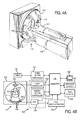
- an x-ray computed tomography (“CT") imaging system 410 includes a gantry 412 representative of a "third generation" CT scanner.
- Gantry 412 has an x-ray source 413 that projects a fan-beam, or cone-beam, of x-rays 414 toward a detector array 416 on the opposite side of the gantry.
- the detector array 416 is formed by a number of detector elements 418 which together sense the projected x-rays that pass through a medical patient 415.
- Each detector element 418 produces an electrical signal that represents the intensity of an impinging x-ray beam and hence the attenuation of the beam as it passes through the patient.
- the gantry 412 and the components mounted thereon rotate about a center of rotation 419 located within the patient 415.
- the rotation of the gantry and the operation of the x-ray source 413 are governed by a control mechanism 420 of the CT system.
- the control mechanism 420 includes an x-ray controller 422 that provides power and timing signals to the x-ray source 413 and a gantry motor controller 423 that controls the rotational speed and position of the gantry 412.
- a data acquisition system (“DAS") 424 in the control mechanism 420 samples analog data from detector elements 418 and converts the data to digital signals for subsequent processing.
- An image reconstructor 425 receives sampled and digitized x-ray data from the DAS 424 and performs high speed image reconstruction. The reconstructed image is applied as an input to a computer 426 which stores the image in a mass storage device 428.
- the computer 426 also receives commands and scanning parameters from an operator via console 430 that has a keyboard.
- An associated display 432 allows the operator to observe the reconstructed image and other data from the computer 426.
- the operator supplied commands and parameters are used by the computer 426 to provide control signals and information to the DAS 424, the x-ray controller 422 and the gantry motor controller 423.
- computer 426 operates a table motor controller 434 which controls a motorized table 436 to position the patient 415 in the gantry 412.
- an embodiment of the invention employs an x-ray system that is designed for use in connection with interventional procedures. It is characterized by a gantry having a C-arm 510 which carries an x-ray source assembly 512 on one of its ends and an x-ray detector array assembly 514 at its other end.
- the gantry enables the x-ray source 512 and detector 514 to be oriented in different positions and angles around a patient disposed on a table 516, while enabling a physician access to the patient.
- the gantry includes an L-shaped pedestal 518 which has a horizontal leg 520 that extends beneath the table 516 and a vertical leg 522 that extends upward at the end of the horizontal leg 520 that is spaced from of the table 516.
- a support arm 524 is rotatably fastened to the upper end of vertical leg 522 for rotation about a horizontal pivot axis 526.
- the pivot axis 526 is aligned with the centerline of the table 516 and the arm 524 extends radially outward from the pivot axis 526 to support a C-arm drive assembly 527 on its outer end.
- the C-arm 510 is slidably fastened to the drive assembly 527 and is coupled to a drive motor (not shown) which slides the C-arm 510 to revolve it about a C-axis 528 as indicated by arrows 530.
- the pivot axis 526 and C-axis 528 intersect each other at an isocenter 536 located above the table 516 and they are perpendicular to each other.
- the x-ray source assembly 512 is mounted to one end of the C-arm 510 and the detector array assembly 514 is mounted to its other end. As will be discussed in more detail below, the x-ray source 512 emits a cone beam of x-rays which are directed at the detector array 514. Both assemblies 512 and 514 extend radially inward to the pivot axis 526 such that the center ray of this cone beam passes through the system isocenter 536. The center ray of the cone beam can thus be rotated about the system isocenter around either the pivot axis 526 or the C-axis 528, or both during the acquisition of x-ray attenuation data from a subject placed on the table 516.
- the x-ray source assembly 512 contains an x-ray source 532 which emits a cone beam 533 of x-rays when energized.
- the center ray 534 passes through the system isocenter 536 and impinges on a two-dimensional flat panel digital detector 538 housed in the detector assembly 514.
- Exemplary flat panel detectors 538 include so-called "small flat panel” detectors, in which the detector array panel 538 is around 20 cm by 20 cm in size. Such a detector panel allows the coverage of a field-of-view of around 12 cm.
- Each element produces an electrical signal that represents the intensity of an impinging x-ray and hence the attenuation of the x-ray as it passes through the patient.
- the x-ray source 532 and detector array 538 are rotated about the system isocenter 536 to acquire x-ray attenuation projection data from different angles.
- the detector array is able to acquire 30 projections, or views, per second and this is the limiting factor that determines how many views can be acquired for a prescribed scan path and speed.
- the control mechanism 540 includes an x-ray controller 542 that provides power and timing signals to the x-ray source 532.
- a data acquisition system (“DAS") 544 in the control mechanism 540 samples data from detector elements 538 and passes the data to an image reconstructor 545.
- the image reconstructor 545 receives digitized x-ray data from the DAS 544 and performs high speed image reconstruction according to the methods of the present invention.
- the reconstructed image is applied as an input to a computer 546 which stores the image in a mass storage device 549 or processes the image further.
- the control mechanism 540 also includes pivot motor controller 547 and a C-axis motor controller 548.
- the motor controllers 547 and 548 provide power to motors in the x-ray system that produce the rotations about respective pivot axis 526 and C-axis 528.
- a program executed by the computer 546 generates motion commands to the motor drives 547 and 548 to move the assemblies 512 and 514 in a prescribed scan path.
- the computer 546 also receives commands and scanning parameters from an operator via console 550 that has a keyboard and other manually operable controls.
- An associated cathode ray tube display 552 allows the operator to observe the reconstructed image and other data from the computer 546.
- the operator supplied commands are used by the computer 546 under the direction of stored programs to provide control signals and information to the DAS 544, the x-ray controller 542 and the motor controllers 547 and 548.
- computer 546 operates a table motor controller 554 which controls the motorized table 516 to position the patient with respect to the system isocenter 536.
- a subject 700 when a subject 700 is positioned in a C-arm x-ray imaging system that utilizes a small flat-panel 702, such as those described above, projection data is acquired only over a limited field-of-view 704.
- a method for producing a prior image and reconstructing a desired image of, for example, a cardiac phase of the subject's heart that both account for the truncated projection data is required.
- the succeeding description provides such methods.
- a reconstruction line 706, A along which projection data is acquired passes through the subject 700.
- the reconstruction line 706 includes a portion that passes through the limited field-of-view 704, ⁇ H , and a portion that passes through a region 708 in the subject with a known attenuation value, ⁇ A , such as an air pocket.
- ⁇ A a known attenuation value
- An x-ray CT imaging system such as the one described above with reference to Figs. 4A and 4B , or an x-ray C-arm imaging system, such as the one described above with reference to Figs. 5A and 5B can be employed to acquire image data in accordance with an embodiment of the present invention.
- Fig. 8 a flowchart setting forth the steps of an image reconstruction method in accordance with the present invention is illustrated. The method begins with the acquisition of an electrocardiogram ("ECG") signal from the subject, as indicated at step 800. This ECG signal is later used to retrospectively gate the acquired image data into M different cardiac phases, P M .
- ECG electrocardiogram
- Data acquisition subsequently begins by acquiring image data in the form of a set of projection views at a first view angle, ⁇ n , as indicated at step 802.
- the x-ray source and detectors are subsequently rotated to a new view angle at step 804, where image data is again acquired. This process is repeated until the x-ray source and detectors have been rotated to a last view angle, ⁇ N , as indicated by decision block 806. After all of the desired image data has been acquired, the acquisition of the ECG signal is stopped.
- a prior image, I P is reconstructed at step 808.
- the prior image is reconstructed using a method that iteratively reconstructs the image as a series of reconstruction lines. For example, instead of having conventional image pixels that are reconstructed and rendered as squares, the reconstructed image has pixels that are reconstructed as lines, which are herein referred to as "reconstruction lines.” As will be described below in detail with respect to Fig. 9 , this method provides a suitable prior image, I P , even from truncated projection data acquired with a small flat-panel detector.
- each cardiac phase image data set includes a plurality of projection views acquired during the gating window, W m , corresponding to a given cardiac phase, P m .
- the original image data acquisition can be prospectively gated such that image data is only acquired at specific time points during the ECG signal. Following this data acquisition scheme, all of the image data acquired during a selected cardiac phase is similarly combined into a cardiac phase image data set.
- a first cardiac phase, P m is selected at step 810.
- a desired image, I of the selected cardiac phase, P m , is subsequently reconstructed using a method that utilizes, in part, the reconstruction methods described above with reference to Figs. 1 , 2 , and 3 .
- Figs. 1 , 2 , and 3 the reconstruction methods described above with reference to Figs. 1 , 2 , and 3 .
- a desired image, I for each cardiac phase is reconstructed in a manner similar to the production of the prior image, I P , above in step 808.
- a desired image, I is reconstructed for each cardiac phase, P m , in this manner until an image for each of the desired cardiac phases has been reconstructed, as decided at process block 814. If all of the desired images have not been reconstructed, a next cardiac phase, P m , is selected at step 816 and the above described image reconstruction method is repeated.
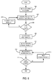
- a differential projection data set is produced from the acquired image data, as indicated at step 900.
- An exemplary method for producing a differential projection data set is described, for example, in U.S. Patent No. 7,251,307 .
- the differential projection data, g d is calculated in terms of the detector coordinates, u, v , and the source parameter, t .
- D is the distance from the x-ray source to the detector isocenter
- g is the acquired projection data.
- a first reconstruction line, A is selected for processing, as indicated at step 902.
- A For a given reconstruction line, A, passing through a small region of interest where the CT number is known a priori, an iterative process is performed on the reconstruction line, A, to reconstruct image pixel values of the pixels on the line.
- the reconstruction process begins by producing an initial estimate image, f 0 ( x ) ( k ) , of the reconstructed reconstruction line, ⁇ , as indicated at step 904.
- HU Hounsfield unit
- the initial estimate image includes image intensity values for the line in the resultant image matrix that is associated with the selected reconstruction line, A.
- the differential projection data set is backprojected onto the corresponding reconstruction line A to obtain a differential image, DBP ( x ), as indicated at step 906.
- DBP differential image
- ⁇ H the portion of the reconstruction line, A, that passes through the scan field-of-view ("FOV"), ⁇ H , is backprojected.
- the initial estimate image, f 0 ( x ) ( k ) is transformed, as indicated at step 908.
- the initial estimate image, f 0 ( x ) ( k ) is transformed using a Hilbert transform to produce a transformed initial estimate image, Hf ( x ).
- MHf ( x ) a combined estimate image, MHf ( x ), is produced as indicated at step 910.
- an updated estimate image, f 1 ( x ) ( k ) , of the reconstructed reconstruction line, A, is produced, as indicated at step 912.
- the updated estimate image, f 1 ( x ) ( k ) is produced by calculating the inverse Hilbert transform of the combined estimate image, MHf ( x ).
- a loop is now entered, in which the reconstructed reconstruction line, A, is iteratively estimated.
- the updated estimate image, f 1 ( x ) ( k ) is forward projected in order to produce estimate projection data, as indicated at step 914.
- the estimate projection data is then subtracted from the acquired image data in order to produce difference projection data, as indicated at step 916.
- the result of this difference is backprojected onto the reconstruction line, A, to produce a difference image, as indicated at step 918, that is then minimized, as indicated at step 920.
- the difference image is minimized using a convex optimization method that is constrained using the consistency condition of Eqn.
- a stopping criterion such as the stopping criterion in Eqn.
- the minimized difference image is stored as an "image line,” as indicated at step 926, and the entire process repeated for the next reconstruction line, as indicated at step 928.
- the corresponding image lines are combined to produce the prior image, I P , as indicated at step 932.
- each reconstruction line corresponds to one row or column of the image matrix for the prior image, I P .
- the prior image, I P is produced by forming a full image matrix by appropriately combining the individually reconstructed image lines.
- a differential cardiac phase projection data set is first produced from the selected cardiac phase image data set, as indicated at step 1000.
- the available data for a specific cardiac phase is very limited. For example, only about 10 projection view angles may be included in a given cardiac phase image data set. Therefore, some projections from other cardiac phases are included in the differential cardiac phase projection data set without substantially contaminating the temporal information. To achieve this, a "sliding window" type weighting function is utilized.
- a first cardiac phase is selected for processing, as indicated at step 1002.
- an iterative minimization process is performed in a similar manner to the method employed to produce the prior image, I P .
- a first reconstruction is selected, as indicated at step 1004.
- the differential cardiac phase projection data set is backprojected onto the corresponding reconstruction line A to obtain a differential image, DBP ( x ), as indicated at step 1008. It is noted, however, that because of the truncation that occurs with the small flat-panel detector, only the portion of the reconstruction line, A, that passes through the scan field-of-view ("FOV"), ⁇ H , is backprojected.
- the initial estimate image, f 0 ( x ) ( k ) is transformed, as indicated at step 1010.
- the initial estimate image, f 0 ( x ) ( k ) is transformed using a Hilbert transform to produce a transformed initial estimate image, Hf ( x ).
- MHf ( x ) a combined estimate image, MHf ( x ), is produced as indicated at step 1012.
- an updated estimate image, f 1 ( x ) ( k ) , of the reconstructed reconstruction line, A, is produced, as indicated at step 1014.
- the updated estimate image, f 1 ( x ) ( k ) is produced by calculating the inverse Hilbert transform of the combined estimate image, MHf ( x ).
- a loop is now entered, in which the reconstructed reconstruction line, A, is iteratively estimated.
- the updated estimate image, f 1 ( x ) ( k ) is forward projected in order to produce estimate projection data, as indicated at step 1016.
- the estimate projection data is then subtracted from the corresponding acquired image data associated with the given cardiac phase in order to produce difference projection data, as indicated at step 1018.
- the result of this difference is backprojected onto the reconstruction line, A, in order to produce a difference image, as indicated at step 1020, which is then minimized, as indicated at step 1022.
- This minimization is a two step process. For example, first the difference image is minimized using a convex optimization method that is constrained using the consistency condition of Eqn.
- the second minimization includes the performance of a prior image constrained compressed sensing ("PICCS") method, such as those described in detail above with respect to Figs. 1 , 2 , and 3 .
- PICCS prior image constrained compressed sensing
- a determination is then made at decision block 1024 whether this minimized difference image satisfies a stopping criterion, such as the stopping criterion in Eqn. (15). If not, the minimized difference image is selected as the initial estimate image for a next iteration, as indicated at step 1026. Steps 1010-1022 are then repeated and the determination again made at decision block 1024 as to whether the stopping criterion has been met.
- the minimized difference image is stored as an "image line,” as indicated at step 1028, and the entire process repeated for the next reconstruction line, as indicated at step 1030.
- the corresponding projection images are combined to produce the desired image of the selected cardiac phase, I , as indicated at step 1034.
- a determination is then made at decision block 1036 as to whether images for all of the desired cardiac phases have been reconstructed. If not, then the next cardiac phase is selected at step 1038, and steps 1004-1034 are repeated to produce a desired image, I , for the newly selected cardiac phase.
- the subject's respiration can be monitored with a respiration monitoring device, such as a respiratory belt, and image data retrospectively gated based on the measured respiratory information.
- a respiration monitoring device such as a respiratory belt
- image data retrospectively gated based on the measured respiratory information.
- motion such as internal organ motion, can be compensated for when reconstructing images.
Claims (15)
- Verfahren zum Erzeugen eines Bildes eines Probanden mit einem Röntgenbildsystem, wobei das Verfahren die Schritte aufweist:a) Erfassen (802), mit dem Röntgenbildsystem, eines Bilddatensatzes entlang einer Serie von Projektionsansichten bei jedem von einer Vielzahl von Projektionsansichtswinkeln;b) Erzeugen (808) eines Vorabbildes des Probanden;c) Auswählen eines Schätzbildes des Probanden;d) Erzeugen eines spärlichen Bildes des Probanden, wobei das Vorabbild und das Schätzbild verwendet werden; unde) Rekonstruieren eines gewünschten Bildes des Probanden, wobei das spärliche Bild, das Schätzbild und der erfasste Bilddatensatzes verwendet werden; dadurch gekennzeichnet dass Schritt b) durchgeführt wird indem jede Linie in einer entsprechenden Bildmatrix rekonstruiert wird, wobei ein iterativer Schätzprozess verwendet wird, um ein Vorabbild zu formen, in dem Rundungsartefakte unterdrückt sind.
- Verfahren gemäß Anspruch 1, bei dem Schritt b) umfasst Erzeugen (904) einer anfänglichen Bildschätzung für jede Linie in der Bildmatrix indem:i) Setzen eines jeden Bildintensitätswerts in einem Teil einer jeden anfänglichen Bildschätzung, der zu einem gewählten Material gehört und entlang der entsprechenden Linie in der Bildmatrix angesiedelt ist, auf einen bekannten Abschwächungswert; undii) Setzen eines jeden Bildintensitätswerts in jeder anfänglichen Bildschätzung der nicht zu dem gewählten Material gehört auf Null.
- Verfahren gemäß Anspruch 2, bei dem Schritt b) weiter umfasst:iii) Erzeugen (900) eines Differenzbilddatensatzes aus dem erfassten Bilddatensatz;iv) Erzeugen (906) eines Differenzbildes für jede Linie in dem Bildmatrixsatz, wobei der erzeugte Differenzbilddatensatz verwendet wird;v) Erzeugen (910) eines kombinierten Bildes für jede Linie in der Bildmatrix, indem das entsprechende anfängliche Schätzbild und das Differenzbild kombiniert werden;vi) Erzeugen (918) eines Differenzbildes, das jeder Linie in der Bildmatrix entspricht, wobei das entsprechende erzeugte kombinierte Bild und die erfassten Bilddaten verwendet werden;vii) Minimieren (920) eines jeden Differenzbilds nach Maßgabe einer Konsistenzbedingung; undviii) Kombinieren (932) eines jeden minimierten Differenzbildes um das Vorabbild zu erzeugen.
- Verfahren zum Erzeugen eines Bildes eines Probanden mit einem Röntgenbildsystem, wobei das Verfahren die Schritte aufweist:a) Erfassen (802), mit dem Röntgenbildsystem, eines Bilddatensatzes entlang einer Serie von Projektionsansichten bei jedem von einer Vielzahl von Projektionsansichtswinkeln;b) Erzeugen (808) eines Vorabbildes des Probanden;c) Auswählen eines Schätzbildes des Probanden;d) Erzeugen eines spärlichen Bildes des Probanden, wobei das Vorabbild und das Schätzbild verwendet werden; unde) Rekonstruieren eines gewünschten Bildes des Probanden, wobei das spärliche Bild, das Schätzbild und der erfasste Bilddatensatzes verwendet werden; dadurch gekennzeichnet dass Schritt b) durchgeführt wird durchi) Erzeugen (900) eines Differenzbilddatensatzes aus dem erfassten Bilddatensatz;ii) Erzeugen (904) eines anfänglichen Schätzbildes für jede Linie in einer Bildmatrix;iii) Erzeugen (906) eines Differenzbildes für jede Linie in dem Bildmatrixsatz, wobei der erzeugte Differenzbilddatensatz verwendet wird;iv) Erzeugen (910) eines kombinierten Bildes für jede Linie in der Bildmatrix, indem das entsprechende anfängliche Schätzbild und das Differenzbild kombiniert werden;v) Erzeugen (918) eines Differenzbildes, das jeder Linie in der Bildmatrix entspricht, wobei das entsprechende erzeugte kombinierte Bild und die erfassten Bilddaten verwendet werden;vi) Minimieren (920) eines jeden Differenzbildes nach Maßgabe einer Konsistenzbedingung; undvii) Kombinieren (932) eines jeden minimierten Differenzbildes um das Vorabbild zu erzeugen.
- Verfahren gemäß Anspruch 4, bei dem Schritt b)ii) umfasst Setzen eines jeden Bildintensitätswerts in dem anfänglichen Schätzbild, der zu einem gewählten Material gehört, das entlang der entsprechenden Linie in der Bildmatrix angesiedelt ist, auf einen bekannten Abschwächungswert und Setzen eines jeden Bildintensitätswerts in dem anfänglichen Schätzbild der nicht zu dem gewählten Material gehört auf Null.
- Verfahren gemäß Anspruch 4, bei dem Schritt b)iv) umfasst Durchführen (908) einer Hilbert-Transformation für jedes anfängliche Schätzbild vor dem Durchführen des Kombinierens.
- Verfahren gemäß Anspruch 4, bei dem Schritt b)v) umfasst:Durchführen einer inversen Hilbert-Transformation für jedes kombinierte Bild;Erzeugen einer Vielzahl von Projektionsschätzdaten, indem jedes transformierte kombinierte Bild vorwärts projiziert wird;Erzeugen einer Vielzahl von Differenzprojektionsdaten, indem jede der Vielzahl von Projektionsschätzdaten von den entsprechenden erfassten Bilddaten subtrahiert wird; undRekonstruieren eines Differenzbildes für jede Linie in der Bildmatrix aus jeder der entsprechenden Vielzahl von Differenzprojektionsdaten.
- Verfahren gemäß Anspruch 4, bei dem jedes minimierte Differenzbild einer anderen Linie in der Bildmatrix entspricht, und Schritt b)vii) umfasst Erzeugen des Vorabbildes, indem eine Vorabbildmatrix aus den minimierten Differenzbildern geformt wird.
- Verfahren gemäß Anspruch 4, bei dem Schritt a) außerdem umfasst Erfassen (800) eines Elektrokardiogramm (ECG) Signals von dem Probanden und Korrelieren des Bilddatensatzes mit dem ECG Signal, das erfasst ist, und Schritt c) umfasst Rekonstruieren eines Bildes des Herzes des Probanden.
- Verfahren gemäß Anspruch 9, bei dem die Schritte c)-e) wiederholt werden, um eine Vielzahl von Bilder zu erzeugen, wobei jeder der Vielzahl der Bilder eine andere Kardiophase des Herzes des Probanden anzeigt.
- Verfahren gemäß Anspruch 9, bei dem Schritt c) umfasst:i) Erzeugen einer Vielzahl von Kardiophasendatensätzen, wobei das erfasste ECG Signal und der erfasste Bilddatensatz verwendet wird;ii) Erzeugen (1000) einer Vielzahl von Differenzkardiophasendatensätzen aus der Vielzahl von Kardiodatensätzen;iii) Erzeugen (1006) eines anfänglichen Schätzbildes für jede Linie in jeder der Vielzahl von Bildmatrizen, die zu jeder einer jeweiligen Vielzahl von Kardiophasen gehören;iv) Erzeugen eines Differenzbildes für jede Linie in jeder der Vielzahl von Bildmatrizen, wobei die erzeugte Vielzahl von Differenzkardiophasendatensätze verwendet wird;v) Erzeugen (1012) eines kombinierten Bildes für jede Linie in jeder der Vielzahl von Bildmatrizen, indem das entsprechende anfängliche Schätzbild und Differenzbild kombiniert werden;vi) Erzeugen (1020) eines Differenzbildes, das jeder Linie in jeder der Vielzahl von Bildmatrizen entspricht, wobei das entsprechende erzeugte kombinierte Bild und Bilddaten, die mit der Projektionsansicht verknüpft sind, verwendet werden;vii) Minimieren (1022) eines jeden der Differenzbilder unter der Maßgabe einer Konsistenzbedingung; undviii) Kombinieren eines jeden der minimierten Differenzbilder zum Erzeugen des Schätzbildes.
- Verfahren gemäß Anspruch 11, bei dem er Schritt c)ii) umfasst Setzen eines jeden Bildintensitätswerts in dem anfänglichen Schätzbild, der zu einem gewählten Material gehört, das entlang der entsprechenden Linie in der Bildmatrix angesiedelt ist, auf einen bekannten Abschwächungswert und Setzen eines jeden Bildintensitätswerts in dem anfänglichen Schätzbild der nicht zu dem gewählten Material gehört auf einen Bildintensitätswert in einer entsprechenden Linie in dem erzeugten Vorabbild.
- Verfahren gemäß Anspruch 11, bei dem der Schritt c)v) umfasst Durchführen (1010) einer Hilbert-Transformation für jedes anfängliche Schätzbild vor dem Durchführen des Kombinierens.
- Verfahren gemäß Anspruch 114, bei dem Schritt c)vi) umfasst:Durchführen einer inversen Hilbert-Transformation für jedes kombinierte Bild;Erzeugen einer Vielzahl von Projektionsschätzdaten, indem jedes transformierte kombinierte Bild vorwärts projiziert wird;Erzeugen einer Vielzahl von Differenzprojektionsdaten, indem jede der Vielzahl von Projektionsschätzdaten von den entsprechenden erfassten Bilddaten subtrahiert wird; undRekonstruieren eines Differenzbildes für jede Linie in jeder der Vielzahl von Bildmatrizen aus jeder der entsprechenden Vielzahl von Differenzprojektionsdaten.
- Verfahren gemäß Anspruch 5 oder 12, bei dem das gewählte Matrial ist zumindest eines ausgewählt aus Luft, die eine bekannten Abschwächungswert von ungefähr - 1000 Hounsfieldeinheiten hat, und Lungengewebe, das einen bekannten Abschwächungswert von ungefähr -800 Hounsfieldeinheiten hat.
Applications Claiming Priority (2)
| Application Number | Priority Date | Filing Date | Title |
|---|---|---|---|
| US11831408P | 2008-11-26 | 2008-11-26 | |
| PCT/US2009/065920 WO2010062956A1 (en) | 2008-11-26 | 2009-11-25 | Method for prior image constrained image reconstruction in cardiac cone beam computed tomography |
Publications (2)
| Publication Number | Publication Date |
|---|---|
| EP2349008A1 EP2349008A1 (de) | 2011-08-03 |
| EP2349008B1 true EP2349008B1 (de) | 2015-02-25 |
Family
ID=41668230
Family Applications (1)
| Application Number | Title | Priority Date | Filing Date |
|---|---|---|---|
| EP09768268.6A Active EP2349008B1 (de) | 2008-11-26 | 2009-11-25 | Verfahren zur eingeschränkten bildrekonstruktion eines vorherigen bildes in der kardialen konusstrahl-computertomographie |
Country Status (4)
| Country | Link |
|---|---|
| US (1) | US8326054B2 (de) |
| EP (1) | EP2349008B1 (de) |
| JP (1) | JP5580833B2 (de) |
| WO (1) | WO2010062956A1 (de) |
Families Citing this family (30)
| Publication number | Priority date | Publication date | Assignee | Title |
|---|---|---|---|---|
| DE102009048302B4 (de) * | 2009-10-05 | 2011-07-07 | Siemens Aktiengesellschaft, 80333 | Korrektur von Trunkierungen bei einer MR-Bildgebung |
| US8761478B2 (en) * | 2009-12-15 | 2014-06-24 | General Electric Company | System and method for tomographic data acquisition and image reconstruction |
| US8204172B1 (en) * | 2010-03-17 | 2012-06-19 | General Electric Company | System and method of prior image constrained image reconstruction using short scan image data and objective function minimization |
| US8890522B2 (en) | 2010-04-02 | 2014-11-18 | General Electric Company | Accelerated pseudo-random data magnetic resonance imaging system and method |
| US8520928B2 (en) * | 2010-07-12 | 2013-08-27 | Arizona Board Of Regents On Behalf Of The University Of Arizona | System and method for motion-compensated compressed sensing for dynamic imaging |
| FR2965651B1 (fr) * | 2010-10-01 | 2012-09-28 | Gen Electric | Reconstruction tomographique d'un objet en mouvement |
| CN103501702B (zh) * | 2011-04-28 | 2015-09-02 | 株式会社日立医疗器械 | 医用图像处理装置、医用图像处理方法 |
| US9159146B2 (en) * | 2011-07-08 | 2015-10-13 | Hitachi Medical Corporation | Image reconstruction device and image reconstruction method configured to perform iteratively reconstructed image using weight coefficient |
| DE102011080733A1 (de) * | 2011-08-10 | 2013-02-14 | Siemens Aktiengesellschaft | Verfahren und Vorrichtung zur phasenkorrelierten Bildrekonstruktion in der medizinischen Bildgebung |
| WO2013187970A2 (en) * | 2012-05-14 | 2013-12-19 | The General Hospital Corporation | Method for coded-source phase contrast x-ray imaging |
| WO2013181635A1 (en) * | 2012-06-01 | 2013-12-05 | The Johns Hopkins University | Information propagation in prior-image-based reconstruction |
| EP2976626A4 (de) * | 2013-03-22 | 2016-09-21 | Univ New York | Computerzugängliches medium zur modulierung einer röntgenstrahlintensität |
| JP6492005B2 (ja) * | 2013-04-08 | 2019-03-27 | 株式会社日立製作所 | X線ct装置、再構成演算装置、及び再構成演算方法 |
| TWI517093B (zh) | 2013-10-11 | 2016-01-11 | Univ Nat Yang Ming | Computer tomography reconstruction method |
| KR20150058858A (ko) * | 2013-11-21 | 2015-05-29 | 삼성전자주식회사 | 영상 복원 유닛, 방사선 촬영 장치 및 영상 복원 방법 |
| US9330456B2 (en) | 2014-04-29 | 2016-05-03 | General Electric Company | Systems and methods for regularized Fourier analysis in x-ray phase contrast imaging |
| US9898840B2 (en) | 2014-05-15 | 2018-02-20 | General Electric Company | Systems and methods for continuous motion breast tomosynthesis |
| US9955932B2 (en) | 2014-10-22 | 2018-05-01 | General Electric Company | Apparatus and method for tomosynthesis image acquisition |
| US11467272B2 (en) | 2014-10-30 | 2022-10-11 | Koninklijke Philips N.V. | Compressive sensing in forming ultrasound images |
| US9836861B2 (en) | 2014-12-12 | 2017-12-05 | Samsung Electronics Co., Ltd. | Tomography apparatus and method of reconstructing tomography image |
| US9924909B2 (en) | 2015-08-04 | 2018-03-27 | General Electric Company | System and method for tomosynthesis image acquisition |
| DE102015219622A1 (de) * | 2015-10-09 | 2017-04-13 | Siemens Healthcare Gmbh | Rekonstruktion einer Abbildung anhand einer oder mehrerer Bildgebungsmodalitäten |
| US10076292B2 (en) | 2015-10-16 | 2018-09-18 | General Electric Company | Systems and methods for x-ray tomography having retrograde focal positioning |
| US9805481B2 (en) * | 2016-01-22 | 2017-10-31 | General Electric Company | System and method for regularized reconstruction of phase contrast computerized tomography |
| JP6753798B2 (ja) * | 2017-02-21 | 2020-09-09 | 株式会社日立製作所 | 医用撮像装置、画像処理方法及びプログラム |
| US10517553B2 (en) * | 2017-03-29 | 2019-12-31 | General Electric Company | C-arm imaging system with multiple automated independent rotational axes |
| US11246529B2 (en) * | 2018-07-13 | 2022-02-15 | Northeastern University | Method to localize small and high contrast inclusions in ill-posed model-based imaging modalities |
| US11498536B2 (en) | 2019-01-31 | 2022-11-15 | Toyota Motor Engineering & Manufacturing North America, Inc. | Systems, vehicles, and methods for trailer sway control |
| CA3124052C (en) * | 2020-06-08 | 2022-05-10 | Guangzhou Computational Super-Resolution Biotech Co., Ltd. | Systems and methods for image processing |
| US11908044B2 (en) | 2021-06-17 | 2024-02-20 | GE Precision Healthcare LLC | Systems and methods for computed tomography image reconstruction |
Family Cites Families (26)
| Publication number | Priority date | Publication date | Assignee | Title |
|---|---|---|---|---|
| JPS59221763A (ja) * | 1983-06-01 | 1984-12-13 | Hitachi Ltd | 動的画像処理方式 |
| CA1274922A (en) | 1987-09-11 | 1990-10-02 | Terence Taylor | Region of interest tomography employing a differential scanning technique |
| US6841998B1 (en) | 2001-04-06 | 2005-01-11 | Mark Griswold | Magnetic resonance imaging method and apparatus employing partial parallel acquisition, wherein each coil produces a complete k-space datasheet |
| WO2005003804A1 (en) | 2003-07-02 | 2005-01-13 | Universität Zürich | K-t blast and k-t sense magnetic resonance imaging |
| US7646924B2 (en) | 2004-08-09 | 2010-01-12 | David Leigh Donoho | Method and apparatus for compressed sensing |
| EP1828985A1 (de) * | 2004-11-24 | 2007-09-05 | Wisconsin Alumni Research Foundation | Fächerstrahl- und conusstrahl-bildrekonstruktion unter verwendung gefilterter rückprojektion differenzierter projektionsdaten |
| WO2007008530A1 (en) | 2005-07-08 | 2007-01-18 | Wisconsin Alumni Research Foundation | Backprojection reconstruction method for ct imaging |
| EP1902424B1 (de) | 2005-07-08 | 2009-11-11 | Wisconsin Alumni Research Foundation | Bildrekonstruktion unter Nebenbedingungen |
| JP5113061B2 (ja) | 2005-09-22 | 2013-01-09 | ウイスコンシン アラムナイ リサーチ ファウンデーシヨン | 運動コード化mr画像の高度に限定された再構成 |
| JP5123192B2 (ja) | 2005-09-22 | 2013-01-16 | ウイスコンシン アラムナイ リサーチ ファウンデーシヨン | 機能的磁気共鳴イメージング用の、画像の取得及び再構成の方法 |
| WO2007037937A1 (en) | 2005-09-22 | 2007-04-05 | Wisconsin Alumni Research Foundation | Reconstruction of images of the beating heart using a highly constrained backprojection |
| US7408347B2 (en) | 2005-09-22 | 2008-08-05 | Wisconsin Alumni Research Foundation | Highly constrained magnetic resonance spectroscopy image reconstruction method |
| US7358730B2 (en) | 2005-09-22 | 2008-04-15 | Wisconsin Alumni Research Foundation | Diffusion tensor imaging using highly constrained image reconstruction method |
| DE102005051620A1 (de) * | 2005-10-27 | 2007-05-03 | Siemens Ag | Verfahren zur Rekonstruktion einer tomographischen Darstellung eines Objektes |
| US7289049B1 (en) | 2006-08-21 | 2007-10-30 | L3 Communications Integrated Systems L.P. | Method and apparatus for compressed sensing |
| US7558414B2 (en) | 2006-09-11 | 2009-07-07 | Case Western Reserve University | Iterative image reconstruction |
| EP1959397B1 (de) * | 2007-02-19 | 2019-08-07 | Wisconsin Alumni Research Foundation | Iterative HYPR-Rekonstruktion von medizinischen Bildern |
| EP1959396B1 (de) | 2007-02-19 | 2012-01-18 | Wisconsin Alumni Research Foundation | Verfahren zur lokalisierten und stark eingeschränkten Bildrekonstruktion |
| US7817838B2 (en) * | 2007-05-24 | 2010-10-19 | University Of Utah Research Foundation | Method and system for constrained reconstruction of imaging data using data reordering |
| US8825138B2 (en) | 2007-09-17 | 2014-09-02 | Wisconsin Alumni Research Foundation | Method for reducing motion artifacts in highly constrained medical images |
| US8111810B2 (en) | 2007-11-13 | 2012-02-07 | Wisconsin Alumni Research Foundation | Method for producing highly constrained ultrasound images |
| EP2232446B1 (de) * | 2007-12-20 | 2013-04-17 | Wisconsin Alumni Research Foundation | Verfahren für eingeschränkte bildrekonstruktion mit vorhergehendem bild |
| EP2232444B1 (de) * | 2007-12-20 | 2011-10-12 | Wisconsin Alumni Research Foundation | Verfahren für dynamische eingeschränkte bildrekonstruktion mit vorhergehendem bild |
| US8218907B2 (en) * | 2008-01-14 | 2012-07-10 | Wisconsin Alumni Research Foundation | Method for prior image constrained progressive image reconstruction |
| US8472688B2 (en) * | 2008-04-17 | 2013-06-25 | Wisconsin Alumni Research Foundation | Method for image reconstruction employing sparsity-constrained iterative correction |
| US7916828B1 (en) * | 2010-01-06 | 2011-03-29 | General Electric Company | Method for image construction |
-
2009
- 2009-11-25 EP EP09768268.6A patent/EP2349008B1/de active Active
- 2009-11-25 WO PCT/US2009/065920 patent/WO2010062956A1/en active Application Filing
- 2009-11-25 US US12/626,366 patent/US8326054B2/en active Active
- 2009-11-25 JP JP2011537741A patent/JP5580833B2/ja active Active
Also Published As
| Publication number | Publication date |
|---|---|
| US8326054B2 (en) | 2012-12-04 |
| WO2010062956A1 (en) | 2010-06-03 |
| US20100128958A1 (en) | 2010-05-27 |
| JP5580833B2 (ja) | 2014-08-27 |
| EP2349008A1 (de) | 2011-08-03 |
| JP2012509722A (ja) | 2012-04-26 |
Similar Documents
| Publication | Publication Date | Title |
|---|---|---|
| EP2349008B1 (de) | Verfahren zur eingeschränkten bildrekonstruktion eines vorherigen bildes in der kardialen konusstrahl-computertomographie | |
| EP2240906B1 (de) | Verfahren für durch ein vorheriges bild beschränkte progressive bildrekonstruktion | |
| EP2441051B1 (de) | Method for dynamic prior image constrained image reconstruction | |
| EP2232446B1 (de) | Verfahren für eingeschränkte bildrekonstruktion mit vorhergehendem bild | |
| EP2232444B1 (de) | Verfahren für dynamische eingeschränkte bildrekonstruktion mit vorhergehendem bild | |
| EP2973411B1 (de) | System und verfahren zur gleichzeitigen bildartefaktreduzierung und tomografischen rekonstruktion | |
| US7221728B2 (en) | Method and apparatus for correcting motion in image reconstruction | |
| US8781243B2 (en) | Method for constrained reconstruction of high signal-to-noise ratio images | |
| US20080199063A1 (en) | Iterative Highly Constrained Image Reconstruction Method | |
| US8548568B2 (en) | Methods and apparatus for motion compensation | |
| US10417793B2 (en) | System and method for data-consistency preparation and image reconstruction |
Legal Events
| Date | Code | Title | Description |
|---|---|---|---|
| PUAI | Public reference made under article 153(3) epc to a published international application that has entered the european phase |
Free format text: ORIGINAL CODE: 0009012 |
|
| 17P | Request for examination filed |
Effective date: 20110511 |
|
| AK | Designated contracting states |
Kind code of ref document: A1 Designated state(s): AT BE BG CH CY CZ DE DK EE ES FI FR GB GR HR HU IE IS IT LI LT LU LV MC MK MT NL NO PL PT RO SE SI SK SM TR |
|
| DAX | Request for extension of the european patent (deleted) | ||
| 17Q | First examination report despatched |
Effective date: 20130723 |
|
| GRAP | Despatch of communication of intention to grant a patent |
Free format text: ORIGINAL CODE: EPIDOSNIGR1 |
|
| INTG | Intention to grant announced |
Effective date: 20140904 |
|
| GRAS | Grant fee paid |
Free format text: ORIGINAL CODE: EPIDOSNIGR3 |
|
| GRAA | (expected) grant |
Free format text: ORIGINAL CODE: 0009210 |
|
| AK | Designated contracting states |
Kind code of ref document: B1 Designated state(s): AT BE BG CH CY CZ DE DK EE ES FI FR GB GR HR HU IE IS IT LI LT LU LV MC MK MT NL NO PL PT RO SE SI SK SM TR |
|
| REG | Reference to a national code |
Ref country code: GB Ref legal event code: FG4D |
|
| RIN1 | Information on inventor provided before grant (corrected) |
Inventor name: TANG, JIE Inventor name: CHEN, GUANG-HONG |
|
| REG | Reference to a national code |
Ref country code: CH Ref legal event code: EP |
|
| REG | Reference to a national code |
Ref country code: IE Ref legal event code: FG4D |
|
| REG | Reference to a national code |
Ref country code: NL Ref legal event code: T3 |
|
| REG | Reference to a national code |
Ref country code: DE Ref legal event code: R096 Ref document number: 602009029592 Country of ref document: DE Effective date: 20150409 |
|
| REG | Reference to a national code |
Ref country code: AT Ref legal event code: REF Ref document number: 711217 Country of ref document: AT Kind code of ref document: T Effective date: 20150415 |
|
| REG | Reference to a national code |
Ref country code: AT Ref legal event code: MK05 Ref document number: 711217 Country of ref document: AT Kind code of ref document: T Effective date: 20150225 |
|
| REG | Reference to a national code |
Ref country code: LT Ref legal event code: MG4D |
|
| PG25 | Lapsed in a contracting state [announced via postgrant information from national office to epo] |
Ref country code: LT Free format text: LAPSE BECAUSE OF FAILURE TO SUBMIT A TRANSLATION OF THE DESCRIPTION OR TO PAY THE FEE WITHIN THE PRESCRIBED TIME-LIMIT Effective date: 20150225 Ref country code: SE Free format text: LAPSE BECAUSE OF FAILURE TO SUBMIT A TRANSLATION OF THE DESCRIPTION OR TO PAY THE FEE WITHIN THE PRESCRIBED TIME-LIMIT Effective date: 20150225 Ref country code: HR Free format text: LAPSE BECAUSE OF FAILURE TO SUBMIT A TRANSLATION OF THE DESCRIPTION OR TO PAY THE FEE WITHIN THE PRESCRIBED TIME-LIMIT Effective date: 20150225 Ref country code: ES Free format text: LAPSE BECAUSE OF FAILURE TO SUBMIT A TRANSLATION OF THE DESCRIPTION OR TO PAY THE FEE WITHIN THE PRESCRIBED TIME-LIMIT Effective date: 20150225 Ref country code: NO Free format text: LAPSE BECAUSE OF FAILURE TO SUBMIT A TRANSLATION OF THE DESCRIPTION OR TO PAY THE FEE WITHIN THE PRESCRIBED TIME-LIMIT Effective date: 20150525 Ref country code: FI Free format text: LAPSE BECAUSE OF FAILURE TO SUBMIT A TRANSLATION OF THE DESCRIPTION OR TO PAY THE FEE WITHIN THE PRESCRIBED TIME-LIMIT Effective date: 20150225 |
|
| PG25 | Lapsed in a contracting state [announced via postgrant information from national office to epo] |
Ref country code: IS Free format text: LAPSE BECAUSE OF FAILURE TO SUBMIT A TRANSLATION OF THE DESCRIPTION OR TO PAY THE FEE WITHIN THE PRESCRIBED TIME-LIMIT Effective date: 20150625 Ref country code: GR Free format text: LAPSE BECAUSE OF FAILURE TO SUBMIT A TRANSLATION OF THE DESCRIPTION OR TO PAY THE FEE WITHIN THE PRESCRIBED TIME-LIMIT Effective date: 20150526 Ref country code: AT Free format text: LAPSE BECAUSE OF FAILURE TO SUBMIT A TRANSLATION OF THE DESCRIPTION OR TO PAY THE FEE WITHIN THE PRESCRIBED TIME-LIMIT Effective date: 20150225 Ref country code: LV Free format text: LAPSE BECAUSE OF FAILURE TO SUBMIT A TRANSLATION OF THE DESCRIPTION OR TO PAY THE FEE WITHIN THE PRESCRIBED TIME-LIMIT Effective date: 20150225 |
|
| PG25 | Lapsed in a contracting state [announced via postgrant information from national office to epo] |
Ref country code: SK Free format text: LAPSE BECAUSE OF FAILURE TO SUBMIT A TRANSLATION OF THE DESCRIPTION OR TO PAY THE FEE WITHIN THE PRESCRIBED TIME-LIMIT Effective date: 20150225 Ref country code: EE Free format text: LAPSE BECAUSE OF FAILURE TO SUBMIT A TRANSLATION OF THE DESCRIPTION OR TO PAY THE FEE WITHIN THE PRESCRIBED TIME-LIMIT Effective date: 20150225 Ref country code: DK Free format text: LAPSE BECAUSE OF FAILURE TO SUBMIT A TRANSLATION OF THE DESCRIPTION OR TO PAY THE FEE WITHIN THE PRESCRIBED TIME-LIMIT Effective date: 20150225 Ref country code: RO Free format text: LAPSE BECAUSE OF FAILURE TO SUBMIT A TRANSLATION OF THE DESCRIPTION OR TO PAY THE FEE WITHIN THE PRESCRIBED TIME-LIMIT Effective date: 20150225 Ref country code: CZ Free format text: LAPSE BECAUSE OF FAILURE TO SUBMIT A TRANSLATION OF THE DESCRIPTION OR TO PAY THE FEE WITHIN THE PRESCRIBED TIME-LIMIT Effective date: 20150225 |
|
| REG | Reference to a national code |
Ref country code: DE Ref legal event code: R097 Ref document number: 602009029592 Country of ref document: DE |
|
| PG25 | Lapsed in a contracting state [announced via postgrant information from national office to epo] |
Ref country code: PL Free format text: LAPSE BECAUSE OF FAILURE TO SUBMIT A TRANSLATION OF THE DESCRIPTION OR TO PAY THE FEE WITHIN THE PRESCRIBED TIME-LIMIT Effective date: 20150225 |
|
| PG25 | Lapsed in a contracting state [announced via postgrant information from national office to epo] |
Ref country code: IT Free format text: LAPSE BECAUSE OF FAILURE TO SUBMIT A TRANSLATION OF THE DESCRIPTION OR TO PAY THE FEE WITHIN THE PRESCRIBED TIME-LIMIT Effective date: 20150225 |
|
| PLBE | No opposition filed within time limit |
Free format text: ORIGINAL CODE: 0009261 |
|
| STAA | Information on the status of an ep patent application or granted ep patent |
Free format text: STATUS: NO OPPOSITION FILED WITHIN TIME LIMIT |
|
| 26N | No opposition filed |
Effective date: 20151126 |
|
| PG25 | Lapsed in a contracting state [announced via postgrant information from national office to epo] |
Ref country code: SI Free format text: LAPSE BECAUSE OF FAILURE TO SUBMIT A TRANSLATION OF THE DESCRIPTION OR TO PAY THE FEE WITHIN THE PRESCRIBED TIME-LIMIT Effective date: 20150225 |
|
| PG25 | Lapsed in a contracting state [announced via postgrant information from national office to epo] |
Ref country code: BE Free format text: LAPSE BECAUSE OF FAILURE TO SUBMIT A TRANSLATION OF THE DESCRIPTION OR TO PAY THE FEE WITHIN THE PRESCRIBED TIME-LIMIT Effective date: 20150225 |
|
| PG25 | Lapsed in a contracting state [announced via postgrant information from national office to epo] |
Ref country code: LU Free format text: LAPSE BECAUSE OF FAILURE TO SUBMIT A TRANSLATION OF THE DESCRIPTION OR TO PAY THE FEE WITHIN THE PRESCRIBED TIME-LIMIT Effective date: 20151125 Ref country code: MC Free format text: LAPSE BECAUSE OF FAILURE TO SUBMIT A TRANSLATION OF THE DESCRIPTION OR TO PAY THE FEE WITHIN THE PRESCRIBED TIME-LIMIT Effective date: 20150225 |
|
| REG | Reference to a national code |
Ref country code: CH Ref legal event code: PL |
|
| PG25 | Lapsed in a contracting state [announced via postgrant information from national office to epo] |
Ref country code: LI Free format text: LAPSE BECAUSE OF NON-PAYMENT OF DUE FEES Effective date: 20151130 Ref country code: CH Free format text: LAPSE BECAUSE OF NON-PAYMENT OF DUE FEES Effective date: 20151130 |
|
| REG | Reference to a national code |
Ref country code: IE Ref legal event code: MM4A |
|
| REG | Reference to a national code |
Ref country code: FR Ref legal event code: ST Effective date: 20160729 |
|
| PG25 | Lapsed in a contracting state [announced via postgrant information from national office to epo] |
Ref country code: IE Free format text: LAPSE BECAUSE OF NON-PAYMENT OF DUE FEES Effective date: 20151125 |
|
| PG25 | Lapsed in a contracting state [announced via postgrant information from national office to epo] |
Ref country code: FR Free format text: LAPSE BECAUSE OF NON-PAYMENT OF DUE FEES Effective date: 20151130 |
|
| PG25 | Lapsed in a contracting state [announced via postgrant information from national office to epo] |
Ref country code: BG Free format text: LAPSE BECAUSE OF FAILURE TO SUBMIT A TRANSLATION OF THE DESCRIPTION OR TO PAY THE FEE WITHIN THE PRESCRIBED TIME-LIMIT Effective date: 20150225 Ref country code: HU Free format text: LAPSE BECAUSE OF FAILURE TO SUBMIT A TRANSLATION OF THE DESCRIPTION OR TO PAY THE FEE WITHIN THE PRESCRIBED TIME-LIMIT; INVALID AB INITIO Effective date: 20091125 Ref country code: SM Free format text: LAPSE BECAUSE OF FAILURE TO SUBMIT A TRANSLATION OF THE DESCRIPTION OR TO PAY THE FEE WITHIN THE PRESCRIBED TIME-LIMIT Effective date: 20150225 |
|
| PG25 | Lapsed in a contracting state [announced via postgrant information from national office to epo] |
Ref country code: CY Free format text: LAPSE BECAUSE OF FAILURE TO SUBMIT A TRANSLATION OF THE DESCRIPTION OR TO PAY THE FEE WITHIN THE PRESCRIBED TIME-LIMIT Effective date: 20150225 |
|
| PG25 | Lapsed in a contracting state [announced via postgrant information from national office to epo] |
Ref country code: TR Free format text: LAPSE BECAUSE OF FAILURE TO SUBMIT A TRANSLATION OF THE DESCRIPTION OR TO PAY THE FEE WITHIN THE PRESCRIBED TIME-LIMIT Effective date: 20150225 Ref country code: MT Free format text: LAPSE BECAUSE OF FAILURE TO SUBMIT A TRANSLATION OF THE DESCRIPTION OR TO PAY THE FEE WITHIN THE PRESCRIBED TIME-LIMIT Effective date: 20150225 |
|
| PG25 | Lapsed in a contracting state [announced via postgrant information from national office to epo] |
Ref country code: PT Free format text: LAPSE BECAUSE OF FAILURE TO SUBMIT A TRANSLATION OF THE DESCRIPTION OR TO PAY THE FEE WITHIN THE PRESCRIBED TIME-LIMIT Effective date: 20150225 Ref country code: MK Free format text: LAPSE BECAUSE OF FAILURE TO SUBMIT A TRANSLATION OF THE DESCRIPTION OR TO PAY THE FEE WITHIN THE PRESCRIBED TIME-LIMIT Effective date: 20150225 |
|
| P01 | Opt-out of the competence of the unified patent court (upc) registered |
Effective date: 20230425 |
|
| PGFP | Annual fee paid to national office [announced via postgrant information from national office to epo] |
Ref country code: NL Payment date: 20231013 Year of fee payment: 15 |
|
| PGFP | Annual fee paid to national office [announced via postgrant information from national office to epo] |
Ref country code: GB Payment date: 20231006 Year of fee payment: 15 |
|
| PGFP | Annual fee paid to national office [announced via postgrant information from national office to epo] |
Ref country code: DE Payment date: 20230929 Year of fee payment: 15 |