EP2348787A1 - Distributing system for the communication between distributed base stations, and distributing unit therefor - Google Patents
Distributing system for the communication between distributed base stations, and distributing unit therefor Download PDFInfo
- Publication number
- EP2348787A1 EP2348787A1 EP10305076A EP10305076A EP2348787A1 EP 2348787 A1 EP2348787 A1 EP 2348787A1 EP 10305076 A EP10305076 A EP 10305076A EP 10305076 A EP10305076 A EP 10305076A EP 2348787 A1 EP2348787 A1 EP 2348787A1
- Authority
- EP
- European Patent Office
- Prior art keywords
- stations
- spatially
- enb
- distribution
- concerned
- Prior art date
- Legal status (The legal status is an assumption and is not a legal conclusion. Google has not performed a legal analysis and makes no representation as to the accuracy of the status listed.)
- Ceased
Links
- 230000003287 optical effect Effects 0.000 description 26
- 230000001413 cellular effect Effects 0.000 description 6
- 239000000835 fiber Substances 0.000 description 2
- 239000011159 matrix material Substances 0.000 description 2
- 230000004931 aggregating effect Effects 0.000 description 1
- 230000002457 bidirectional effect Effects 0.000 description 1
- 230000003750 conditioning effect Effects 0.000 description 1
- 238000009223 counseling Methods 0.000 description 1
- 230000007613 environmental effect Effects 0.000 description 1
- 238000009434 installation Methods 0.000 description 1
- 238000000034 method Methods 0.000 description 1
- 239000013307 optical fiber Substances 0.000 description 1
Images




Classifications
-
- H—ELECTRICITY
- H04—ELECTRIC COMMUNICATION TECHNIQUE
- H04W—WIRELESS COMMUNICATION NETWORKS
- H04W92/00—Interfaces specially adapted for wireless communication networks
- H04W92/16—Interfaces between hierarchically similar devices
- H04W92/20—Interfaces between hierarchically similar devices between access points
-
- H—ELECTRICITY
- H04—ELECTRIC COMMUNICATION TECHNIQUE
- H04W—WIRELESS COMMUNICATION NETWORKS
- H04W88/00—Devices specially adapted for wireless communication networks, e.g. terminals, base stations or access point devices
- H04W88/08—Access point devices
Definitions
- the invention relates to a distributing system for linking a multiple of spatially distributed stations which communicate among each other, according to the preamble of claim 1, and to a distribution unit according to the preamble of claim 3.
- Such information may be raw data like a digitized part of an input signal received at an antenna, it may be the data re ceived therefrom by demodulating such signal, it may be data obtained by evaluating feedback from mobile stations, it may be data obtained by joint processing own information and information from other base stations or the like.
- the data may include environmental measuring values or statistical data.
- This object according to the invention is achieved by a distributing system according to the teaching of claim 1, and a distribution unit according to the teaching of claim 3.
- a control network underlying such network of base stations of a cellular radio network is arranged in clusters with a center station and a couple of surrounding stations each.
- One such cluster is shown as a dotted hexagon A k with a center station a k .
- An other such cluster is shown as dashed hexagon A k-1 with a center station a k+1
- the corners of these hexagons also carry base stations.
- Center station a k is connected in both directions to each of its surrounding (neighboring) stations on the dotted hexagon A k by links depicted as dotted arrows;
- center station a k+1 is connected in both directions to each of its surrounding (neighboring) stations on the dashed hexagon A k-1 by links depicted as dashed arrows.
- Stations a k and both are center stations in their own cluster and surrounding (neighboring) stations in the respective other cluster.
- the counseling links are depicted as drawn through arrows.
- the structure of such control network is like the structure of a cellular radio network itself, principles relating to the used resources like frequency reuse may be adopted by using resources in a recurring way.
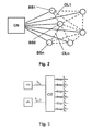
- Figure 2 shows a central node CN, a base station BS0, and several other base stations BS1 to BSn. From the other base stations only BS1 and BSn are labeled.
- All these base stations BS0 to BSn are directly linked (not necessarily with fibers dedicated only to such links) to the central node CN via optical links shown drawn through, but not labeled. They are in part directly linked to one another via optical links shown in dashed lines; only the optical links linking base station BS0 with base stations BS1 and BSn are labeled as OL1 and OLn respectively.
- Base stations not neighboring like BS1 and BSn in this example, are not directly linked, but could be linked nevertheless, if requested.
- an optical interface as shown in figure 3 is used between the base station and the links.
- An optical splitter OS combines and splits links coming from an optical transmitter oTx and going to an optical receiver oRx in the base station and combines and splits the optical fibers to and from the neighboring base stations.
- Such optical splitter OS would also direct the combined incoming signals to the optical transmitter oTx, but this does not disturb, apart from the power loss. Alternatively, this could be circumvented for example by inserting a suitable optical bandpass filter that blocks all alien wavelength signals.
- Figure 4 shows a combination of the optical parts of two base stations of the kind as depicted in figure 3 together with the connection there between.
- the reference signs used in figure 4 are the same as those used in figure 3 except for distinguishing extensions 2 and 5, respectively.
- the present invention now suggests to spatially aggregating the optical splitters OSx dedicated to the individual stations together with the links interconnecting them.
- An advanced example of such network is shown in figure 5 .
- the single stations building a couple of stations here are designated as enhanced nodeBs, eNB; the optical splitters OSx here are depicted as trapezoids.
- the common connects of such splitters at the short parallel sides of the trapezoids are leading to the respective enhanced nodeBs, eNB; the remaining connects at the long parallel sides of the trapezoids are meshed amongst each other building a network as known form figure 4 .
- splitter box SB It is suggested to house the whole spatially aggregated parts of this network in a single housing to build a distribution unit further on called splitter box SB.
- the spatially distributed stations here the enhanced nodeBs, eNB
- each are connected to a common higher level station HLS
- the links between the higher level station and the spatially distributed stations is directed via the splitter box SB.
- an additional power splitter PS and additional diplexers DIPL are inserted between the link to the higher level station HLS and the links to the enhanced nodeBs, eNB.
- wavelength or frequency schemes instead of the diplexers DIPL also additional inputs of the optical splitters could be used.
- the additional power splitter PS could also be integrated into the splitter box SB.
- wavelength or frequency schemes instead of the optical splitters OS an alternative could be to use multiplexers and demultiplexers for wavelength division multiplex, WDMMD, in combination with power splitters PS. This would result in replacing the configuration shown in figure 4 with that shown in figure 7 .
- splitter boxes SB present inputs and outputs for extending the intermediate network by cascading the splitter boxes.
- Exemplary splitter box extension points SBEP and a high level station extension point HLSEP is shown.
- splitter boxes SB could also include further elements, the diplexers DIPL of which have already been mentioned.
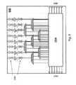
- Figure 6 shows bidirectional optical amplifiers bOA (two possible positions are shown) and an optical switch matrix OSM as further such examples.
- the optical switch matrix OSM could act as remotely controllable optical jumpers.
- optical filters, as included in the diplexers DIPL could be inserted where else otherwise needed.
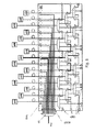
- Figure 8 shows exemplary some networks including distributing systems and distribution units according to the invention.
- the higher level stations are optical line terminations OLT heading such distributing system.
- optical network terminations ONT of e.g. GPON based FTTH networks are connected to the optical line terminations OLT via splitter boxes including power splitters PS and distributing networks DN.
- Figures 8a, 8b, and 8c show different stages of expansion of such access network.
Landscapes
- Engineering & Computer Science (AREA)
- Computer Networks & Wireless Communication (AREA)
- Signal Processing (AREA)
- Mobile Radio Communication Systems (AREA)
Abstract
Description
- The invention relates to a distributing system for linking a multiple of spatially distributed stations which communicate among each other, according to the preamble of
claim 1, and to a distribution unit according to the preamble of claim 3. - A distributing system according to the preamble of
claim 1 was described in our patent applicationEP 09305871.7 - There the starting point was that neighboring base stations in cellular radio networks exchange large bulks of information, conventionally via optical data links. To reach short response times,the stations in principle are fully meshed, what means that each such station is directly linked to each other station (or at least to its nearest stations).
- The problem there was that each such base station needs input from neighboring stations. Retrieving such input information from the respective other base stations by known polling techniques is cumbersome and time consuming Corresponding problems may arise in other situations, where couples of stations cooperate.
- Such information may be raw data like a digitized part of an input signal received at an antenna, it may be the data re ceived therefrom by demodulating such signal, it may be data obtained by evaluating feedback from mobile stations, it may be data obtained by joint processing own information and information from other base stations or the like.
- In other situations the data may include environmental measuring values or statistical data.
- There the information intended for all neighboring stations is multiplexed into a broadcast and sent to each such station, and each of these stations itself selects the information it needs.
- Here as well as there the problem could arise in relation to other kinds of stations too, where then of course the same solution could be used. Also here, in the following both, problem as well as solution, will be described in terms of such base stations.
- The conditioning of the data streams reported there is not of importance here; there is no need to describe and understand it for understanding the present invention.
- As also mentioned in the above cited application it is not only the mere delay on the connecting links, but moreover the delay caused by switching and routing of the connecting links.
- The more or less complete meshing of a couple of stations requires a great deal of installation of cables. It is an object of the present invention to make the network structure clearer.
- This object according to the invention is achieved by a distributing system according to the teaching of
claim 1, and a distribution unit according to the teaching of claim 3. - In contrast to the starting point the distribution and combining of distributed data streams is performed at one common place,from which only one (bi-directional) link extends to the single stations.
- This has also the advantage that at this single place further tasks may be performed like tying the whole set of such stations to a higher level station, introducing amplifiers, switches, and the like. The chance that a potential failure in such network can be found at this single place is high and reduces OEM costs.
- Further improvements and embodiments of the subject invention are to be found in the subclaims and in the following description.
- In the following the invention will be described with the aid of the accompanying drawings, in which:
- Figure 1
- shows a part of a control network underlying a network of base stations of a cellular radio network as described in a prior application as an example of a distributing system according to the invention.
- Figure 2
- shows a part of a cellular radio network, which can be implemented as an example of a distributing system according to the invention.
- Figure 3
- shows the optical part of a base station as described in the prior application.
- Figure 4
- show the optical part of two base stations of the kind as depicted in
figure 3 together with the connection there between. - Figure
- 5 shows an example of a distribution system according to the invention interconnecting a couple of stations including a distributing unit according to the invention, as well as an extension thereof to also connect those stations to a higher level station.
- Figure 6
- shows an example of a distributing unit according to the invention including some further possible exten- sions.
- Figure 7
- shows an alternative of what is shown in
figure 4 . - Figure 8
- shows exemplary some networks including distributing systems and distribution units according to the invention.
- Based on
figure 1 the starting point as described in the cited prior application: - Cellular radio networks mostly are illustrated as having a topology of regular hexagons, in the middle of which a base station each is situated. A control network connecting such network of base stations then also has the topology of regular hexagons, as in
figure 1 . - Practically such networks not only deviate therefrom in the form of the topology and in the number of neighboring stations, but also in the fact, that, depending on the actual need, there might be neighboring stations that are not directly connected and others might be directly connected without being neighbors.
- A control network underlying such network of base stations of a cellular radio network is arranged in clusters with a center station and a couple of surrounding stations each. One such cluster is shown as a dotted hexagon Ak with a center station ak. An other such cluster is shown as dashed hexagon Ak-1 with a center station ak+1 The corners of these hexagons also carry base stations. Center station ak is connected in both directions to each of its surrounding (neighboring) stations on the dotted hexagon Ak by links depicted as dotted arrows; center station ak+1is connected in both directions to each of its surrounding (neighboring) stations on the dashed hexagon Ak-1 by links depicted as dashed arrows. Stations ak and both are center stations in their own cluster and surrounding (neighboring) stations in the respective other cluster. The counseling links are depicted as drawn through arrows. As the structure of such control network is like the structure of a cellular radio network itself, principles relating to the used resources like frequency reuse may be adopted by using resources in a recurring way.
- Please note that the denominations of the elements in this figure depart from the respective denominations in the following figure.
-
Figure 2 shows a central node CN, a base station BS0, and several other base stations BS1 to BSn. From the other base stations only BS1 and BSn are labeled. - All these base stations BS0 to BSn are directly linked (not necessarily with fibers dedicated only to such links) to the central node CN via optical links shown drawn through, but not labeled. They are in part directly linked to one another via optical links shown in dashed lines; only the optical links linking base station BS0 with base stations BS1 and BSn are labeled as OL1 and OLn respectively.
- In principle all neighboring base stations are directly linked, but even this principle might be breached depending on the actual situation, e.g. when there is no road link between two neighboring radio cells. But this is not an aspect of the present invention.
- Base stations not neighboring, like BS1 and BSn in this example, are not directly linked, but could be linked nevertheless, if requested.
- Assuming that we use only single fibers as links for both directions between either of the base stations, an optical interface as shown in
figure 3 is used between the base station and the links. An optical splitter OS combines and splits links coming from an optical transmitter oTx and going to an optical receiver oRx in the base station and combines and splits the optical fibers to and from the neighboring base stations. Such optical splitter OS would also direct the combined incoming signals to the optical transmitter oTx, but this does not disturb, apart from the power loss. Alternatively, this could be circumvented for example by inserting a suitable optical bandpass filter that blocks all alien wavelength signals. -
Figure 4 shows a combination of the optical parts of two base stations of the kind as depicted infigure 3 together with the connection there between. The reference signs used infigure 4 are the same as those used infigure 3 except fordistinguishing extensions 2 and 5, respectively. - The present invention now suggests to spatially aggregating the optical splitters OSx dedicated to the individual stations together with the links interconnecting them. An advanced example of such network is shown in
figure 5 . - The single stations building a couple of stations here are designated as enhanced nodeBs, eNB; the optical splitters OSx here are depicted as trapezoids. The common connects of such splitters at the short parallel sides of the trapezoids are leading to the respective enhanced nodeBs, eNB; the remaining connects at the long parallel sides of the trapezoids are meshed amongst each other building a network as known form
figure 4 . - It is suggested to house the whole spatially aggregated parts of this network in a single housing to build a distribution unit further on called splitter box SB.
- According to an other aspect of the invention in the case that the spatially distributed stations, here the enhanced nodeBs, eNB, each are connected to a common higher level station HLS the links between the higher level station and the spatially distributed stations is directed via the splitter box SB. To this extend in this example an additional power splitter PS and additional diplexers DIPL are inserted between the link to the higher level station HLS and the links to the enhanced nodeBs, eNB. Depending on power, wavelength or frequency schemes instead of the diplexers DIPL also additional inputs of the optical splitters could be used. The additional power splitter PS could also be integrated into the splitter box SB.
- Also depending power, wavelength or frequency schemes instead of the optical splitters OS an alternative could be to use multiplexers and demultiplexers for wavelength division multiplex, WDMMD, in combination with power splitters PS. This would result in replacing the configuration shown in
figure 4 with that shown infigure 7 . - According to an other aspect of the invention such splitter boxes SB present inputs and outputs for extending the intermediate network by cascading the splitter boxes. Exemplary splitter box extension points SBEP and a high level station extension point HLSEP is shown.
- According to an other aspect of the invention such splitter boxes SB could also include further elements, the diplexers DIPL of which have already been mentioned.
Figure 6 shows bidirectional optical amplifiers bOA (two possible positions are shown) and an optical switch matrix OSM as further such examples. The optical switch matrix OSM could act as remotely controllable optical jumpers. Also optical filters, as included in the diplexers DIPL could be inserted where else otherwise needed. -
Figure 8 shows exemplary some networks including distributing systems and distribution units according to the invention. Here the higher level stations are optical line terminations OLT heading such distributing system. In addition to connecting enhanced nodeBs, eNB, also optical network terminations ONT of e.g. GPON based FTTH networks are connected to the optical line terminations OLT via splitter boxes including power splitters PS and distributing networks DN.Figures 8a, 8b, and 8c show different stages of expansion of such access network.
Claims (6)
- Distributing system (fig. 2) for linking a multiple of spatially distributed stations (BS0, BSI, BSn, eNB) which communicate among each other, where for communicating among each other the data destined for the rest of the concerned stations are combined to one common data stream each, that is distributed to the rest of the concerned stations by means of a distribution element (OS, OS2, OS5; WDMMD, PS) via a data link (OL1, OLn) each, characterized in, that distribution elements (OS, OS2, OS5; WDMMD, PS) dedicated to one each of the concerned stations (BSO, BS1, BSn, eNB) are aggregated spatially.
- Distributing system according to claim 1, characterized in, that the spatially distributed stations (BSO, BS1, BSn, eNB) each are connected to a common higher level station (HLS, OLT) and that the links (OL1, OLn) between the higher level station (HLS) and the spatially distributed stations (BS0, BS1, BSn, eNB) are directed via the spatially aggregated distribution elements (OS, OS2, OS5; WDMMD, PS).
- Distribution unit (SP) for a distributing system according to claim 1, characterized in, that it includes the spatially aggregated distribution elements (OS, OS2, OS5; WDMMD, PS),
- Distribution unit (SB) according to claim 3, characterized in, that the distribution elements dedicated to one each of the concerned stations are bi-directional splitting elements with the common connects foreseen for connecting the respective one of the concerned stations and meshed amongst each other via their remaining connects.
- Distribution unit according to claim 3, characterized in, that it is presents inputs and outputs (SBEP, HLSEP) for being cascaded.
- Distribution unit according to claim 3, characterized in, that it further includes amplifiers (bOA), switches (OSM), filters (DIPL) or the like (DIPL).
Priority Applications (1)
| Application Number | Priority Date | Filing Date | Title |
|---|---|---|---|
| EP10305076A EP2348787A1 (en) | 2010-01-22 | 2010-01-22 | Distributing system for the communication between distributed base stations, and distributing unit therefor |
Applications Claiming Priority (1)
| Application Number | Priority Date | Filing Date | Title |
|---|---|---|---|
| EP10305076A EP2348787A1 (en) | 2010-01-22 | 2010-01-22 | Distributing system for the communication between distributed base stations, and distributing unit therefor |
Publications (1)
| Publication Number | Publication Date |
|---|---|
| EP2348787A1 true EP2348787A1 (en) | 2011-07-27 |
Family
ID=42224467
Family Applications (1)
| Application Number | Title | Priority Date | Filing Date |
|---|---|---|---|
| EP10305076A Ceased EP2348787A1 (en) | 2010-01-22 | 2010-01-22 | Distributing system for the communication between distributed base stations, and distributing unit therefor |
Country Status (1)
| Country | Link |
|---|---|
| EP (1) | EP2348787A1 (en) |
Cited By (2)
| Publication number | Priority date | Publication date | Assignee | Title |
|---|---|---|---|---|
| CN105122888A (en) * | 2013-10-21 | 2015-12-02 | 华为技术有限公司 | Routing method between base stations, serving gateway and base station |
| EP3182616A1 (en) | 2015-12-17 | 2017-06-21 | Alcatel Lucent | Method, devices and system for endpoint communication |
Citations (4)
| Publication number | Priority date | Publication date | Assignee | Title |
|---|---|---|---|---|
| GB2319439A (en) * | 1996-11-12 | 1998-05-20 | Hazeltine Corp | Network Architecture for Linking Base Stations |
| EP0899899A2 (en) * | 1997-08-29 | 1999-03-03 | Lucent Technologies Inc. | An apparatus and method for sharing a signaling channel |
| WO2002035767A2 (en) * | 2000-10-26 | 2002-05-02 | Ericsson Inc. | Method to enable peer to peer device communication over bi-directional serial bus |
| WO2004111707A2 (en) * | 2003-06-12 | 2004-12-23 | Ubi Systems, Inc. | Converting signals in passive optical networks |
-
2010
- 2010-01-22 EP EP10305076A patent/EP2348787A1/en not_active Ceased
Patent Citations (4)
| Publication number | Priority date | Publication date | Assignee | Title |
|---|---|---|---|---|
| GB2319439A (en) * | 1996-11-12 | 1998-05-20 | Hazeltine Corp | Network Architecture for Linking Base Stations |
| EP0899899A2 (en) * | 1997-08-29 | 1999-03-03 | Lucent Technologies Inc. | An apparatus and method for sharing a signaling channel |
| WO2002035767A2 (en) * | 2000-10-26 | 2002-05-02 | Ericsson Inc. | Method to enable peer to peer device communication over bi-directional serial bus |
| WO2004111707A2 (en) * | 2003-06-12 | 2004-12-23 | Ubi Systems, Inc. | Converting signals in passive optical networks |
Cited By (6)
| Publication number | Priority date | Publication date | Assignee | Title |
|---|---|---|---|---|
| CN105122888A (en) * | 2013-10-21 | 2015-12-02 | 华为技术有限公司 | Routing method between base stations, serving gateway and base station |
| EP3043598A4 (en) * | 2013-10-21 | 2016-09-28 | Huawei Tech Co Ltd | ROUTING METHOD BETWEEN BASE STATIONS, SERVICE GATEWAY, AND BASE STATION |
| US9942928B2 (en) | 2013-10-21 | 2018-04-10 | Huawei Technologies Co., Ltd. | Routing method between base stations, serving gateway, and base station |
| CN105122888B (en) * | 2013-10-21 | 2019-05-24 | 华为技术有限公司 | Routing method between base stations, serving gateway and base station |
| EP3182616A1 (en) | 2015-12-17 | 2017-06-21 | Alcatel Lucent | Method, devices and system for endpoint communication |
| WO2017102628A1 (en) | 2015-12-17 | 2017-06-22 | Alcatel Lucent | Method, devices and system for endpoint communication |
Similar Documents
| Publication | Publication Date | Title |
|---|---|---|
| US8457496B2 (en) | Optical signal switching device | |
| TWI552536B (en) | Optical data center network system and optical switch | |
| US9252910B2 (en) | Expandable multicast optical switch | |
| US20120114332A1 (en) | Reconfigurable optical add/drop multiplexing device for enabling totally inresistant colorless | |
| CN102648594A (en) | Transponder aggregator without wavelength selector for colorless and directionless multi-order ROADM nodes | |
| CN102868476A (en) | ROADM (Reconfigurable Optical Add Drop Multiplexer) system for selecting cross-linking connection matrix based on wavelength | |
| US8285145B2 (en) | Modular colorless and directionless multi-degree reconfigurable optical add/drop multiplexer node with in-service upgradeability | |
| US9112636B2 (en) | Add and drop switch/aggregator for optical communications networks | |
| CN103197388A (en) | C and L waveband wavelength selecting switch, as well as implementation method and processing unit thereof | |
| US10419148B2 (en) | Optical node | |
| US20030128985A1 (en) | Modular optical network node | |
| US7058303B2 (en) | Optical cross-connecting device | |
| US9693123B2 (en) | Optical switch | |
| CN108886404A (en) | Optical Cross Connect | |
| EP2063562B1 (en) | Photonic cross-connect | |
| US20160301495A1 (en) | Power Efficient Multi-Degree ROADM Using Variable Optical Splitter | |
| EP2348787A1 (en) | Distributing system for the communication between distributed base stations, and distributing unit therefor | |
| Zhao et al. | Architecture and performance of grouped ROADM rings with shared optical amplifier and grouped add/drop ports for hybrid data center network | |
| WO2015151716A1 (en) | Wavelength demultiplexer and wavelength multiplexer using same | |
| US20020186725A1 (en) | Wavelength group wavelength converter and wavelength group exchange using the same | |
| US20050276605A1 (en) | Method of upgrading an optical transmission network, an optical transmission network, and associated optical transmission nodes | |
| US20020197007A1 (en) | Flexible optical network architecture and optical add/drop multiplexer/demultiplexer therefor | |
| EP2299610A1 (en) | Method of exchanging information in a network of stations through optical fibers, network of stations, receiving part and base station | |
| CN104486695A (en) | Optical WDM (wavelength division multiplexing) machine-borne full optical switching network structure | |
| Basch et al. | DWDM system architecture and design trade-offs |
Legal Events
| Date | Code | Title | Description |
|---|---|---|---|
| PUAI | Public reference made under article 153(3) epc to a published international application that has entered the european phase |
Free format text: ORIGINAL CODE: 0009012 |
|
| 17P | Request for examination filed |
Effective date: 20100810 |
|
| AK | Designated contracting states |
Kind code of ref document: A1 Designated state(s): AT BE BG CH CY CZ DE DK EE ES FI FR GB GR HR HU IE IS IT LI LT LU LV MC MK MT NL NO PL PT RO SE SI SK SM TR |
|
| RAP1 | Party data changed (applicant data changed or rights of an application transferred) |
Owner name: ALCATEL LUCENT |
|
| 111Z | Information provided on other rights and legal means of execution |
Free format text: AT BE BG CH CY CZ DE DK EE ES FI FR GB GR HR HU IE IS IT LI LT LU LV MC MK MT NL NO PL PT RO SE SI SK SM TR Effective date: 20130410 |
|
| RAP1 | Party data changed (applicant data changed or rights of an application transferred) |
Owner name: ALCATEL LUCENT |
|
| D11X | Information provided on other rights and legal means of execution (deleted) | ||
| STAA | Information on the status of an ep patent application or granted ep patent |
Free format text: STATUS: THE APPLICATION HAS BEEN REFUSED |
|
| 18R | Application refused |
Effective date: 20160711 |