EP2348677A1 - Method and apparatus for an ethernet connector comprising an integrated PHY - Google Patents
Method and apparatus for an ethernet connector comprising an integrated PHY Download PDFInfo
- Publication number
- EP2348677A1 EP2348677A1 EP11000324A EP11000324A EP2348677A1 EP 2348677 A1 EP2348677 A1 EP 2348677A1 EP 11000324 A EP11000324 A EP 11000324A EP 11000324 A EP11000324 A EP 11000324A EP 2348677 A1 EP2348677 A1 EP 2348677A1
- Authority
- EP
- European Patent Office
- Prior art keywords
- connector
- physical layer
- communication
- operable
- phy
- Prior art date
- Legal status (The legal status is an assumption and is not a legal conclusion. Google has not performed a legal analysis and makes no representation as to the accuracy of the status listed.)
- Ceased
Links
Images


Classifications
-
- H—ELECTRICITY
- H04—ELECTRIC COMMUNICATION TECHNIQUE
- H04L—TRANSMISSION OF DIGITAL INFORMATION, e.g. TELEGRAPHIC COMMUNICATION
- H04L49/00—Packet switching elements
- H04L49/30—Peripheral units, e.g. input or output ports
-
- H—ELECTRICITY
- H04—ELECTRIC COMMUNICATION TECHNIQUE
- H04L—TRANSMISSION OF DIGITAL INFORMATION, e.g. TELEGRAPHIC COMMUNICATION
- H04L49/00—Packet switching elements
- H04L49/90—Buffering arrangements
-
- H—ELECTRICITY
- H04—ELECTRIC COMMUNICATION TECHNIQUE
- H04L—TRANSMISSION OF DIGITAL INFORMATION, e.g. TELEGRAPHIC COMMUNICATION
- H04L49/00—Packet switching elements
- H04L49/35—Switches specially adapted for specific applications
- H04L49/351—Switches specially adapted for specific applications for local area network [LAN], e.g. Ethernet switches
-
- H—ELECTRICITY
- H04—ELECTRIC COMMUNICATION TECHNIQUE
- H04L—TRANSMISSION OF DIGITAL INFORMATION, e.g. TELEGRAPHIC COMMUNICATION
- H04L49/00—Packet switching elements
- H04L49/40—Constructional details, e.g. power supply, mechanical construction or backplane
Definitions
- Certain embodiments of the invention relate to wired communication systems. More specifically, certain embodiments of the invention relate to a method and apparatus for an Ethernet connector comprising an integrated PHY.
- Communication devices may incorporate a plurality of features, for example, a mobile phone, a digital camera, an Internet browser, a gaming device, a Bluetooth headphone interface and/or a location device.
- the communication devices may be operable to communicate via a plurality of wire-line and/or wireless networks such as local area networks, wide area networks, wireless local area networks, cellular networks and wireless personal area networks, for example.
- endpoint devices may communicate via various wireless and/or wire-line switches, routers, hubs, access points and/or base stations.
- Twisted pair cabling may be shielded and/or unshielded.
- Shielding may comprise a conductive material that may enable grounding of the cable.
- the shielding may enclose a single pair of twisted wires and/or may enclose a plurality of pairs.
- the shielding may comprise foil and/or a braided sheath, for example. In this regard, the shielding may mitigate cross talk between twisted pairs and/or between a plurality of cables.
- Various properties of a cable for example, wire gauge, safety information, category, verification of testing, inner shielding, outer shielding, no shielding, type of use, such as patch cord, and/or country of manufacture may be imprinted on the cable jacket during manufacture.
- a method and/or apparatus for an Ethernet connector comprising an integrated PHY comprising:
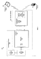
- FIG. 1 is a block diagram illustrating an exemplary connector interface that comprises a connector with an integrated PHY device, in accordance with an embodiment of the invention.
- FIG. 2 is a block diagram illustrating an exemplary connector interface that is capable of wireless communication and comprises a connector with an integrated PHY device, in accordance with an embodiment of the invention.
- FIG. 3 is a block diagram that illustrates an exemplary connector interface that comprises a connector with a plurality of integrated PHY devices, in accordance with an embodiment of the invention.
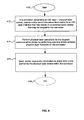
- FIG. 4 is a flow chart illustrating exemplary steps for communicating via a connector comprising an integrated physical layer device, in accordance with an embodiment of the invention.
- Certain embodiments of the invention can be found in a method and apparatus for an Ethernet connector comprising an integrated PHY.
- Various aspects of the invention comprise one or more processors and/or circuits in a connector that may comprise one or more physical layer transceiver devices.
- physical layer functions may be executed by the one or more physical layer transceiver devices within the connector when communicating data via a medium that is communicatively coupled to the connector.
- the physical layer transceiver device may be operable to perform one or more physical layer functions as specified by the Open System Interconnect (OSI) model.
- the physical layer functions may be performed for a communication device that is communicatively coupled to the connector.
- the physical layer functions may comprise one or more OSI layer one functions.
- the one or more physical layer devices may be integrated on one or more chips within the connector.
- the data may be communicated via one or both of wired and/or wireless communication.
- the information may be communicated by the one or more physical layer transceiver devices via a mated corresponding connector that may be coupled to a twisted pair cable.
- the data may be communicated wirelessly, via an antenna and/or a wireless access point that is integrated within the connector.
- the connector may utilize power received via power over Ethernet (POE). Furthermore, power may be transported by the connector utilizing POE.
- the data may be communicated via the one or more physical layer transceiver devices in an Ethernet extended reach mode. A plurality of instances of the connector may be ganged together.
- the connector may comprise a form factor that integrates within a handheld communication device.
- the connector may comprise a form factor that may enable greater than 48 connectors to be integrated in a one rack unit (1RU) face plate. In this manner, electronic design of a circuit board may be simplified and/or interference and/or noise may be mitigated in communication between a connector and various modules within a communication device.
- FIG. 1 is a block diagram illustrating an exemplary connection interface that comprises a connector with an integrated PHY device, in accordance with an embodiment of the invention.
- a communication system 100 comprising a communication device 102 and a connector interface 134.
- the communication device 102 may comprise a host 104, a MAC controller 106, a PHY device 116 and a connector 112.
- the connector interface 134 may comprise the connector 112 comprising a transformer 114, a corresponding connector 120 and a cable 126.
- the communication device 102 may comprise suitable logic, circuitry, interfaces and/or code that may be operable to communicate with other communication devices via the connector interface 134.
- An exemplary embodiment of the communication device 102 may comprise, for example, a router, a switch, a patch panel, a laptop, a portable phone, a media player, a location device, a television, a set-top-box, a camera and/or a gaming device.
- the communication device 102 may be operable to communicate via the connector interface 134 based on one or more of a plurality of different standardized and/or non-standardized communication protocols and/or communication technologies. For example, the communication device 102 may be operable to communicate based on various Ethernet protocols.
- the host 104 may comprise suitable logic, circuitry, interfaces and/or code that may be operable to control one or more aspects of communication via the connector interface 134.
- the host 104 may be communicatively coupled with the MAC controller 106a for communication of data and/or control information.
- the MAC controller 106 may comprise suitable logic, circuitry, interfaces and/or code that may be operable to handle data link layer, OSI layer 2, operability and/or functionality in the communication device 102. In this regard, may be operable to handle addressing and/or access control to a wire-line network and may, for example, enable transmission of Ethernet frames.
- the MAC controller 106 may be operable to buffer, prioritize and/or otherwise coordinate transmission and/or reception of data via the PHY device 116.
- the MAC controller 106 may be operable to perform packetization, depacketization, encapsulation and/or decapsulation of data.
- the MAC controller 106 may be configured to implement Ethernet protocols, such as those based on the IEEE 802.3 standard, for example.
- the MAC controller 106 may be operable to communicate with the host 104 and/or the PHY device 116.
- the connector interface 134 may be configurable to support communication based on a plurality of wire-line, wireless and/or optical communication protocols which may be standardized and/or non-standardized.
- the connector interface 134 may comply with standardized and/or non-standard specifications.
- the connector interface 134 may comply with one or more cabling standards, for example, ISO/IEC and/or TIA standards.
- the connector interface 134 may comprise one or more connectors and/or cables that may comprise the connector 112, the corresponding connector 120 and/or the cable 126.
- the connector 112 and/or the corresponding connector 120 may comprise a PHY device, for example, the connector 112 and/or the corresponding connector 120 may comprise the PHY device 116.
- the PHY device 116 may comprise a transceiver and may be operable to communicate data, for example, multimedia data, to a link partner, for example, via the twisted pair cable 126.
- the PHY device 116 may be operable to communicate with the MAC controller 106 and/or the host 104.
- the connector 112 and/or the corresponding connector 120 may comprise Ethernet connectors such as an RJ45 and/or may comprise other types and/or other styles of connectors; however, the invention is not limited in this regard.
- the connector 112, the corresponding connector 120 and/or the cable 126 may be small enough to fit into a handheld device, for example, a mobile phone, a VOIP phone and/or a laptop.
- the connector 112, the corresponding connector 120 and/or the cable 126 may be small enough to enable greater than 48 connectors to fit into a one rack unit face plate.
- the connector interface 134 may be small enough to fit 96 connectors into a one rack unit face plate, for example.
- the connector interface 134 may be operable to support wireless communication.
- the connector interface 134 may be configurable as a plurality of ganged connectors.
- the connector interface 134, the corresponding connector 120 and/or the connector 112 may comprise modular units.
- the connector interface 134, the corresponding connector 120 and/or the connector 112 may be configurable.
- the connector 112 and/or the corresponding connector 120 may be populated and/or depopulated with various modules or optional features and/or may be configurable, for example, by loading software or firmware and/or by setting hardware.
- United States Patent Application Serial No. _____ (Attorney Docket Number 20745US01) filed on ____, which is incorporated herein by reference in its entirety, may comprise additional information regarding such a connector and/or cabling system.
- Voltage may be supplied to the connector interface 134 in any suitable manner.
- voltage may come from the host 104, from a power source located within the connector interface 134 and/or from power over Ethernet (PoE).
- PoE power over Ethernet
- United States Patent Application (Attorney Docket 20746US01), filed on ____, which is incorporated herein by reference in its entirety, describes connectors and/or cables that may utilize power over Ethernet functionality.
- the connector 112 may comprise suitable logic, circuitry, interfaces and/or code that may be operable to terminate the corresponding connector 120 and/or the cable 126 and/or support communication via the corresponding connector 120 and/or the cable 126.
- the connector 112 may comprise magnetics, for example, the transformer 114.
- the connector 112 may comprise one or more PHY devices, for example, the PHY 116.
- the PHY device 116 may offload PHY functionality from the communication device 102 and may simplify electronic design, reduce noise and/or reduce complexity within the communication device 102.
- the connector 112 and/or the PHY device 116 and may be communicatively coupled to the MAC controller 106 and/or to the host 104.
- the connector 112 may be configurable for wire-line, wireless and/or optical communication, for example, the connector 112 may function as an antenna port.
- the connector 112 may be multifunctional and may be operable to support a plurality of types of communication concurrently and/or sequentially.
- the corresponding connector 120 may comprise an access point and/or antenna circuitry.
- United States Patent Application Serial No. (Attorney Docket Number 20747US01), filed on ____, which is incorporated herein by reference in its entirety, may comprise additional information regarding a connection platform comprising wireless and/or wire-line capability.
- the PHY device 116 may comprise a transceiver and may be operable to communicate data, for example, multimedia data, to a link partner, for example, via the twisted pair cable 126.
- the PHY device 116 may be integrated within the connector 112 and/or within the corresponding connector 120 (not shown) and may be operable to communicate in an upstream and/or a downstream direction at various data rates, for example, ⁇ 10 Mbps, 10 Mbps, 100 Mbps, 1000 Mbps (or 1 Gbps), 10 Gbps, 40 Gbps, and/or other data rates, for example.
- the PHY device 116 may support standards-based data rates and/or non-standard data rates via the corresponding connector 120 and/or the cable 126.
- the PHY device 116 may be configured to handle physical layer requirements, which may comprise, for example, encoding data, packetization, data transfer and serialization/deserialization (SERDES), in instances where such an operation is required. In this regard, the PHY device 116 may perform OSI layer one operations. Although the PHY device 116 is shown within the connector 112, the invention is not so limited and in various embodiments of the invention, the corresponding connector 120 may comprise a PHY device such as the PHY device 116. A PHY device integrated within the corresponding connector 120 may be operable to communicate via the twisted pair cable 126 or may be operable to convert electrical signals from the communication device 102 to optical or wireless signals for transmission.
- PHY device 116 may perform OSI layer one operations.
- the PHY device 116 may comprise an individual port, for example, in a handheld device or it may comprise a plurality of ports, for example, ganged PHY devices.
- the PHY device 116 may comprise one or more chips that may each comprise one or more PHY devices, for example.
- the connector interface 134 comprises a plurality of PHY devices 116
- one or more signals that are communicated to or from one or more of the plurality of PHY devices to or from the MAC controller 106 and/or to or from the host 104 may be aggregated and/or may be communicated via a single trace.
- the PHY device 116 may be configured to communicate with a link partner in an extended reach mode.
- United States Patent Application Serial No. 11/473,205 filed on June 22, 2006 which is incorporated herein by reference in its entirety, may comprise additional information regarding extended reach Ethernet techniques.
- the corresponding connector 120 may be coupled to the cable 126.
- the corresponding connector 120 may be operable to connect to the connector 112 and may be utilized for communication between the communication device 102 and a link partner.
- the corresponding connector 120 may comprise suitable logic, circuitry, interfaces and/or code that may be operable to communicate based on IEEE 802.3 standards and/or extensions and/or variations thereof.
- the corresponding connector 120 may comprise a PHY device such as the PHY device 116.
- the corresponding connector 120 and/or the cable 126 may be configured, for example, during manufacture, by a user and/or by the device 102.
- the connector 112 and/or the corresponding connector 120 may be populated and/or depopulated with various modules or optional features and/or may be configurable, for example, by loading software or firmware and/or setting hardware.
- the corresponding connector 120 may comprise wireless capability, for example, the corresponding connector may comprise an antenna and/or a wireless access point.
- the cable 126 may comprise a copper medium, for example, the cable 126 may comprise any suitable number of pairs of insulated twisted wires. The number of pairs within the cable 126 as well as other factors, such as shielding, the length of the cable and/or wire gauge may determine which protocols and/or which data rates the cable 126 may be operable to support.
- the cable 126 may comprise one or more shields or may be unshielded.
- the shield may comprise, for example, foil and/or a braided sheath around and/or along a length of one or more twisted pairs. For example, one or more individual twisted pairs may be shielded and/or all of the twisted pairs may be shielded together.
- the cable 126 may comprise any suitable category and/or class of cabling, for example, class D, class E, class F and/or category 5, category 6 and/or category 7.
- the communication device 102 may comprise the connector 112 and the corresponding connector 120 and/or the cable 126 may be coupled to the connector 112.
- the connector 112 may comprise one or more wireless, wire-line and/or optical PHY devices, for example, the PHY device 116.
- the host 104 may be operable to communicate and/or perform auto-negotiation via the PHY device 116, the corresponding connector 120 and/or the cable 126. Integration of the PHY device 116 within the connector 112 may offload PHY functionality from the communication device 102. This may enable reduction, modification, aggregation and/or elimination of traces and/or conductors within the communication device 102 that may otherwise carry higher power signals from a cable to a PHY device.
- signals between the connector 112 and the MAC controller 106 may comprise lower power digital signals.
- Offloading the PHY functionality from, for example, a circuit board within the communication device 102, to the connector interface 134 and/or to the connector 112, may enable simplification of electronic design, fewer components, reduction of noise and/or a reduction in complexity, for example, near the connector 112.
- the communication device 110 may comprise a small device, for example, a handled device, a laptop and/or a VOIP phone, a need for valuable surface area and/or layers of a circuit board may be reduced by integrating the PHY device 116 on the connector 112.
- FIG. 2 is a block diagram illustrating an exemplary connector interface that is capable of wireless communication and comprises a connector with an integrated PHY device, in accordance with an embodiment of the invention.
- a communication system 200 comprising a plurality of communication devices 202, 240 and 250.
- the communication device may comprise the host 204, the layer 2 device 204 and the connector 212.
- a connector interface 234 may comprise the connector 212, magnetics 214, a PHY 216, a corresponding connector and/or dongle 220 and antenna circuitry and/or wireless access point 224.
- the communication device 202 may comprise suitable logic, circuitry, interfaces and/or code that may be operable to communicate via one or more of any suitable wireless and/or wire-line interface.
- the communication device 202 may communicate based on IEEE 802.11 and/or variations thereof, Bluetooth, cellular and/or IEEE 802.3 and variations thereof.
- the communication device 202 may comprise one or more of a router, a switch, a patch panel, a laptop, a portable phone, a media player, a location device, television, set-top-box, a camera and/or gaming device, for example.
- the communication device 202 may be operable to communicate based on a plurality of communication interfaces via the connector 212.
- the host 204 may be similar and/or substantially the same as the host 104 described with respect to FIG. 1 .
- the layer 2 device 206 may perform OSI layer 2 functionality and may be communicatively coupled to the PHY device 216 and/or to the host 204.
- the layer 2 device 206 may be similar and/or substantially the same as the MAC controller 106.
- the connector interface 234 may be configurable and/or may be operable to support wired and/or wireless communication.
- the connector interface 234 may comprise the connector 212 that may be referred to as the connector 212, and/or the corresponding connector and/or dongle 220.
- the connector interface 234 may also comprise the antenna circuitry and/or wireless access point 224 that may be integrated within housing of the corresponding connector and/or dongle 220, for example.
- the communication device 202 may comprise the connector 212.
- the connector 212 may comprise the magnetics 214 that may comprise, for example, a transformer.
- the connector 212 may comprise the PHY device 116 which may be integrated within the connector 212.
- the connector 212 may be communicatively coupled to the corresponding connector and/or dongle 220 based on standardized and/or non-standard specifications.
- the connector 212 and the corresponding connector 220 may comprise RJ45 Ethernet connectors in the connector interface 234.
- dimensions of the connector 212 and/or of the corresponding connector 220 may be on a scale that is small enough to fit into a handheld device and/or small enough to enable greater than 48 connectors 212 and/or corresponding connectors 220 to fit into a one rack unit face plate.
- 96 connectors 212 and/or corresponding connectors 220 may fit into a one rack unit face plate.
- the connector interface 234 may comprise a plurality of connectors such as the connector 212 that may be ganged together.
- United States Patent Application Serial No. ____ (Attorney Docket Number 20745US01) filed on ____, which is incorporated herein by reference in its entirety, may comprise additional information regarding such a connector and/or cabling system.
- the connector 212 and/or the corresponding connector 220 may be operable to supply and/or receive power, for example, based on power over Ethernet.
- the connector 212 and/or the PHY device 216 may be configurable to transmit and/or receive wireless communication.
- the connector 212 may function as an antenna port.
- the connector 212 may comprise multifunctional capabilities where a plurality of types of communication may operate concurrently and/or sequentially.
- the connector 212 may receive input from a cable as well as input from an antenna.
- the connector 212 may be configurable.
- the connector 212 may comprise a mechanical or electrical switch or detection mechanism that may be operable to detect whether a cable or an antenna is mated to the connector.
- a cable may be attached that comprises an antenna as well as wire or optical conductors and may be operable to communicate via the plurality of media.
- the corresponding connector and/or dongle 220 may comprise suitable logic, circuitry interfaces and/or code that may be operable to communicate based on one or more of a plurality of communication interfaces.
- the corresponding connector and/or dongle 220 may be operable to communicate with the communication device 202 based on 802.3 and/or extensions and/or variations thereof.
- the corresponding connector and/or dongle 220 may be operable to communicate wirelessly, for example, based on 802.11 and/or extensions and/or variations thereof, with one or more of the communication devices 240 and/or 250.
- the corresponding connector and/or dongle 220 may comprise the antenna circuitry and/or wireless access point 224.
- the corresponding connector and/or dongle 220 may comprise suitable logic, circuitry, interfaces and/or code that may be operable to convert between wireless and wired protocols, for example, between IEEE 302.3 and 802.11. As such, the corresponding connector and/or dongle 220 may be operable to rate match between wired protocol and wireless protocol.
- the antenna circuitry and/or wireless access point 224 may be integrated within a housing of the corresponding connector and/or dongle 220.
- the corresponding connector and/or dongle 220 may comprise a dongle that may be integrated with a corresponding connector where the antenna circuitry and/or wireless access point 224 may be built within a dongle.
- the antenna circuitry and/or wireless access point 224 may comprise an antenna and/or may comprise suitable logic, circuitry, interfaces and/or code that may be operable to process sent and/or received signals.
- each corresponding connector and/or dongle 220 may have its own antenna circuitry and/or wireless access point 224 or two or more units may share antenna circuitry, for example.
- the corresponding connector and/or dongle 220 may be operable to communicate with the communication device 202 based on Ethernet and/or may be operable to communicate wirelessly with one or more of the communication devices 240 and 250.
- wireless communication with the communication devices 240 and/or 250 may be based on one or more variations and/or extensions of IEEE 802.11.
- the corresponding connector and/or dongle 220 may be operable to wirelessly communicate based on wireless technologies such as, for example, Bluetooth, cellular, satellite and/or Zigbee.
- the corresponding connector and/or dongle 220 may convert wire-line signals to wireless signals and vice versa.
- the corresponding connector and/or dongle 220 may be operable to receive power from the connector 212, for example, via power over Ethernet.
- United States Patent Application (Attorney Docket 20746US01), filed on ____, which is incorporated herein by reference in its entirety, describes a connector and/or cabling system that may provide power over Ethernet functionality.
- the communication devices 240 and 250 may comprise suitable logic, circuitry, interfaces and/or code that may be operable to communicate wirelessly with the corresponding connector and/or dongle 220.
- the communication devices may comprise wireless and/or wire-line link partners with regard to the PHY device 216 and/or with regard to the communication device 210.
- the communication devices 240 and/or 250 may be stationary, portable and/or handheld devices.
- the communication devices 240 and/or 250 may comprise one or more of a mobile phone, a media player, a location device, a television, a set-top-box, a camera and/or a gaming device.
- the communication devices 240 and 250 may be a laptop and a handheld device respectively and may be referred to as the laptop 240 and the handheld device 250.
- the laptop 240 and/or handheld device 250 may be operable to communicate wirelessly communication device 202.
- the communication device 202 may be, for example, a switch which may be referred to as the switch 202 and which may comprise the connector 212.
- the connector 212 may comprise the PHY device 216 that may communicate via the corresponding connector and/or dongle 220 and the antenna circuitry and/or wireless access point 224 with the communication device 240, for example.
- the PHY device 216 may communicate with the communication device 240 based on IEEE 802.11 standards via the antenna, for example.
- the PHY device 216 and the corresponding connector and/or dongle 220 may be configured to communicate with each other based on IEEE 802.3 for example.
- the antenna circuitry and/or wireless access point 224 may be operable to convert wireless signals received from the handheld device 250 to Ethernet signals and to communicate the Ethernet signals to the communication device 202 and vice versa.
- FIG. 3 is a block diagram that illustrates an exemplary connector interface that comprises a connector with a plurality of integrated PHY devices, in accordance with an embodiment of the invention.
- the communication system 300 may comprise a communication device 310 and a connector interface 334.
- the communication device 310 may comprise the host 304 and a plurality of layer 2 devices 306 1 , 306 2 , ..., 306 N .
- the connector interface 334 may comprise a connector 312, magnetics 314, a plurality of PHY devices 316 1 , 316 2 , ..., 316 N , a corresponding connector and/or dongle 320, antenna circuitry and/or wireless access point 324 and a cable 326.
- PHY devices 316 1 , 316 2 , ..., 316 N may be referred to as the PHY devices 316.
- layer 2 devices 306 1 , 306 2 , ... , 306 N may be referred to as the layer 2 devices 306.
- the communication device 310 may comprise suitable logic, circuitry, interfaces and/or code that may be operable to communicate based one or more types of wireless and/or one or more types of wire-line technology.
- the communication device 310 may be operable to communicate based on IEEE 802.3 and/or variations and extensions thereof.
- the communication device 310 may be operable to communicate based on one or more of IEEE 802.11, cellular, Bluetooth, satellite and Zigbee wireless technologies, for example.
- the communication device 310 may comprise a laptop, a handheld phone, a media player, a camera, a gaming device, a location device, a switch, a router, a server and/or any suitable combination of devices.
- the communication device 310 may comprise the host 304 and, for example, a plurality of layer 2 devices 306 1 , 306 2 , ..., 306 N .
- One or more of the layer 2 devices 306 1 , 306 2 , ..., 306 N may be communicatively coupled with one or more of the PHY devices 316 1 , 316 2 , ..., 316 N .
- ones of the layer 2 devices 306 may be similar and/or substantially the same as the MAC controller 106 and/or the layer 2 device 206, for example.
- the communication device 310 may comprise the connector 312 and may utilize one or more PHY devices 316 that may be integrated within the connector 312.
- the communication device 310 may be a laptop that may be operable to communicate based on a plurality of communication protocols via a plurality of corresponding PHY devices 316 that may be integrated within the connector 312. Moreover, connectors similar to the connector 312 may be ganged within the communication device 310.
- the connector interface 334 may comprise aspects of all or a portion of the connector interface 134 and/or 234.
- the connector interface 334 may comprise suitable logic, circuitry, interfaces and/or that may be operable to support communication based on a plurality of types of wire-line and/or wireless communication.
- the connector interface 334 for example, may be operable to convert between wired and wireless communication protocols, for example, 802.3 and 802.11.
- the connector 312 may comprise various aspects of the connectors 112 and/or 212.
- the connector 312 may be be communicatively coupled to the corresponding connector 320.
- the connector 312 may comprise the magnetics 316 and/or may comprise a plurality of PHY devices 316 1 , 316 2 , ..., 316 N , Ones of the PHY devices 316 1 , 316 2 , ..., 316 N may be similar and/or substantially the same as the PHY device 116 and/or the PHY device 216.
- a plurality of connectors such as the connector 312 may be ganged together.
- the plurality of PHY devices 316 1 , 316 2 , ..., 316 N may be integrated on a single chip and/or on a plurality of chips within the connector 312. For example, two octal PHY chips may be integrated within the connector 312 and/or may provide 16 ports for the communication device 310.
- the plurality of PHY devices 316 1 , 316 2 , ..., 316 N may comprise a single type of PHY device or may comprise a plurality of PHY types.
- the PHY devices 316 may be operable to support one or more of IEEE 802.3, IEEE 802.11, cellular, Bluetooth, satellite communications, Zigbee and extensions and/or variations thereof.
- One or more of the PHY devices 316 may be configured to communicate with a link partner in an extended reach mode.
- one or more of the PHY devices 316 may be operable to receive and/or deliver power over Ethernet.
- the corresponding connector and/or dongle 320 may comprise aspects that are similar and/or substantially the same as one or both of the corresponding connectors 120 and 220.
- the corresponding connector and/or dongle 320 may support Ethernet communication and/or may optionally comprise a wireless access point and/or an antenna.
- the corresponding connector and/or dongle 320 may optionally comprise the antenna circuitry and/or wireless access point 324 which may be similar and/or substantially the same as the antenna circuitry and/or wireless access point 324.
- the corresponding connector and/or dongle 320 and/or the cable 326 may support wireless and/or wire-line communication to and/or from one or more of the plurality of PHY devices 316 1 , 316 2 , ..., 316 N .
- the corresponding connector and/or dongle 320 and/or the cable 326 may be operable to support one or more of IEEE 802.3, IEEE 802.11, cellular, Bluetooth, satellite communications, Zigbee and extensions and/or variations thereof.
- the cable 326 is optional and may be coupled to the corresponding connector and/or dongle 320.
- the cable 326 may comprise twisted pair wires and/or may be similar and/or substantially the same as the cable 126 described with respect to FIG. 1 .
- the cable 326 may optionally comprise an antenna (not shown) that may radiate outside of any cable shielding.
- the communication device 310 may be accessed based on a plurality of communication protocols via the connector 312 and/or via the plurality of PHY devices 316 1 , 316 2 , ..., 316 N .
- the connector interface 324 may be operable to communicatively couple a plurality of different types of wireless and/or wire-line devices that may communicate based on one or more communication protocols to the communication device 310.
- a user may connect to the connector 312, the corresponding connector 320 that may be coupled to the cable 326 and/or may comprise the antenna circuitry and/or wireless access point 324.
- the communication device 310 may be operable to communicate based on an Ethernet protocol via the cable 326, for example, and/or may concurrently and/or at different times communicate based on one or more wireless protocols via the antenna circuitry and/or wireless access point 324.
- the communication device 310 may comprise one or more connectors such as the connector 312 that may be ganged together in some instances.
- the connectors 312 may be utilized interchangeably.
- a user may connect an Ethernet cable to one instance of the connector 312 in the communication device 310 and may connect a corresponding connector comprising an antenna to another instance of the connector 312 in the communication device 310.
- a user may connect one or more instances of the corresponding connector 326 to one or more instances of the connector 312.
- the communication device 310 may be operable to communicate based on wire-line and/or wireless technologies.
- FIG. 4 is a flow chart illustrating exemplary steps for communicating via a connector comprising an integrated physical layer device, in accordance with an embodiment of the invention.
- the exemplary steps may begin with step 410.
- a connector for example, one or more of the connectors 112, 212 and 312 may comprise an OSI layer 1 physical layer device 116, 216 and/or 316 1 , 316 2 , ..., 316 N .
- the OSI layer 1 physical layer device 116, 216 and/or 316 1 , 316 2 , ..., 316 N may be operable to receive and/or send information from and/or to an OSI layer 2 device 106, 206 and/or 306 1 , 306 2 , ..., 306 N respectively.
- the OSI layer 2 device 106, 206 and/or 306 1 , 306 2 , ..., 306 N may reside on the communication device 110, 210 and/or 310 respectively that may be coupled to the connector 112, 212 and/or 312 respectively.
- step 414 physical layer operations may be offloaded from the coupled communication device 110, 210 and/or 310 by performing wire-line and/or wireless physical layer operations on the connector 112, 212 and/or 312.
- step 416 the physical layer device 116, 216 and/or 316 1 , 316 2 , ..., 316 N within the connector 112, 212 and/or 312 respectively may send and/or receive the information to and/or from a link partner.
- the exemplary steps may end at step 418.
- An embodiment of the invention may comprise one or more processors and/or circuits in a connector, for example, in the connectors 112, the connector 212 and/or the connector 312 that may comprise one or more physical layer transceiver devices (PHY), for example, the PHY 116, the PHY 216 and/or one or more of the PHYs 3161, 3162, ..., 316N respectively.
- PHY physical layer transceiver devices
- physical layer functions may be executed by the one or more physical layer transceiver devices within the connector when communicating data via a medium that is communicatively coupled to the connector, for example, via the twisted pair cable 126 or 226 or via a wireless link described with respect to FIG. 2 .
- the physical layer functions may be performed for a communication device that is communicatively coupled to the connector, for example, the communication device 102, the communication device 202 and/or the communication device 310.
- the physical layer functions may comprise one or more OSI layer one functions.
- the one or more physical layer devices may be integrated on one or more chips within the connector.
- the data may be communicated via one or both of wired and/or wireless communication.
- the data may be communicated by the one or more physical layer transceiver devices via a mated corresponding connector, for example, the connector 120 and/or the connector 320 that may be coupled to a twisted pair cable, for example, the cable 126 or the cable 326 respectively.
- the connector and the corresponding connector may comprise a plug and a receptacle, respectively.
- the connector and the corresponding connector may comprise a receptacle and a plug, respectively.
- the data may be communicated wirelessly, via an antenna and/or a wireless access point 324 that is integrated within the connector 320, for example.
- the connector for example, the connector may utilize power received via power over Ethernet (POE). Furthermore, power may be transported by the connector and/or the corresponding connector utilizing POE.
- POE power over Ethernet
- the data may be communicated via the one or more of the physical layer transceiver devices in an Ethernet extended reach mode.
- a plurality of instances of the connector, for example, of the connector 112, of the connector 212 and/or of the connector 312 may be ganged together.
- the connectors 112, 212 and/or 312 may comprise a form factor that integrates within a handheld communication device, for example, the communication device 202 may be a handheld device.
- the connectors 112, 212 and/or 312 may comprise a form factor that may enable greater than 48 connectors to be integrated in a one rack unit (1 RU) faceplate, for example, the communication device 310 may comprise a 1 RU faceplate.
- Another embodiment of the invention may provide a machine and/or computer readable storage and/or medium, having stored thereon, a machine code and/or a computer program having at least one code section executable by a machine and/or a computer, thereby causing the machine and/or computer to perform the steps as described herein for an Ethernet connector comprising an integrated PHY.
- the present invention may be realized in hardware, software, or a combination of hardware and software.
- the present invention may be realized in a centralized fashion in at least one computer system or in a distributed fashion where different elements may be spread across several interconnected computer systems. Any kind of computer system or other apparatus adapted for carrying out the methods described herein is suited.
- a typical combination of hardware and software may be a general-purpose computer system with a computer program that, when being loaded and executed, controls the computer system such that it carries out the methods described herein.
- the present invention may also be embedded in a computer program product, which comprises all the features enabling the implementation of the methods described herein, and which when loaded in a computer system is able to carry out these methods.
- Computer program in the present context means any expression, in any language, code or notation, of a set of instructions intended to cause a system having an information processing capability to perform a particular function either directly or after either or both of the following: a) conversion to another language, code or notation; b) reproduction in a different material form.
Landscapes
- Engineering & Computer Science (AREA)
- Computer Networks & Wireless Communication (AREA)
- Signal Processing (AREA)
- Telephone Set Structure (AREA)
- Mobile Radio Communication Systems (AREA)
Abstract
Description
- This application makes reference to, claims priority to, and claims the benefit of United States Provisional Application Serial No.
61/298,076, filed on January 25, 2010 - This application makes reference to:
- United States Patent Application Serial No. ____ (Attorney Docket Number 20740US01) which was filed on ____;
- United States Patent Application Serial No. ____ (Attorney Docket Number 20743US01) which was filed on ____;
- United States Patent Application Serial No. ____ (Attorney Docket Number 20744US01) which was filed on ____;
- United States Patent Application Serial No. ____ (Attorney Docket Number 20745US01) which was filed on ____;
- United States Patent Application Serial No. ____ (Attorney Docket Number 20746US01) which was filed on _____;
- United States Patent Application Serial No. ____ (Attorney Docket Number 20747US01) which was filed on ____;
- United States Patent Application Serial No. ___ (Attorney Docket Number 20748US01) which was filed on ____; and
- United States Patent Application Serial No.
11/473,205 which was filed on June 22, 2006 - Each of the above stated applications is hereby incorporated herein by reference in its entirety.
- Certain embodiments of the invention relate to wired communication systems. More specifically, certain embodiments of the invention relate to a method and apparatus for an Ethernet connector comprising an integrated PHY.
- Communication devices may incorporate a plurality of features, for example, a mobile phone, a digital camera, an Internet browser, a gaming device, a Bluetooth headphone interface and/or a location device. In this regard, the communication devices may be operable to communicate via a plurality of wire-line and/or wireless networks such as local area networks, wide area networks, wireless local area networks, cellular networks and wireless personal area networks, for example. In this regard, endpoint devices may communicate via various wireless and/or wire-line switches, routers, hubs, access points and/or base stations.
- Many communication devices may communicate via twisted pair cables which may comprise pairs of copper wire that are twisted together. Various numbers of twists or turns in the wire pairs may enable mitigation of common mode electromagnetic interference. Twisted pair cabling may be shielded and/or unshielded. Shielding may comprise a conductive material that may enable grounding of the cable. The shielding may enclose a single pair of twisted wires and/or may enclose a plurality of pairs. The shielding may comprise foil and/or a braided sheath, for example. In this regard, the shielding may mitigate cross talk between twisted pairs and/or between a plurality of cables. Various properties of a cable, for example, wire gauge, safety information, category, verification of testing, inner shielding, outer shielding, no shielding, type of use, such as patch cord, and/or country of manufacture may be imprinted on the cable jacket during manufacture.
- Further limitations and disadvantages of conventional and traditional approaches will become apparent to one of skill in the art, through comparison of such systems with the present invention as set forth in the remainder of the present application with reference to the drawings.
- A method and/or apparatus for an Ethernet connector comprising an integrated PHY.
According to an aspect, a method for communication is provided, the method comprising: - performing utilizing one or more processors and/or circuits in a connector, wherein said one or more processors and/circuits comprise one or more physical layer transceiver devices:
- executing physical layer functions within said connector utilizing said one or more physical layer transceiver devices when communicating data via a medium that is communicatively coupled to said connector.
- utilizing power received via power over Ethernet; and
- transporting power via said connector utilizing power over Ethernet.
- one or more processors, and/or circuits within in a connector wherein said one or more processors and/or circuits comprise one or more physical layer transceiver devices, said one or more processors and/or circuits are operable to:
- execute physical layer functions within said connector utilizing said one or more physical layer transceiver devices when communicating data via a medium that is communicatively coupled to said connector.
- utilize power received via power over Ethernet; and
- transport power via said connector, utilizing power over Ethernet.
- Various advantages, aspects and novel features of the present invention, as well as details of an illustrated embodiment thereof, will be more fully understood from the following description and drawings.
-
FIG. 1 is a block diagram illustrating an exemplary connector interface that comprises a connector with an integrated PHY device, in accordance with an embodiment of the invention. -
FIG. 2 is a block diagram illustrating an exemplary connector interface that is capable of wireless communication and comprises a connector with an integrated PHY device, in accordance with an embodiment of the invention. -
FIG. 3 is a block diagram that illustrates an exemplary connector interface that comprises a connector with a plurality of integrated PHY devices, in accordance with an embodiment of the invention. -
FIG. 4 is a flow chart illustrating exemplary steps for communicating via a connector comprising an integrated physical layer device, in accordance with an embodiment of the invention. - Certain embodiments of the invention can be found in a method and apparatus for an Ethernet connector comprising an integrated PHY. Various aspects of the invention comprise one or more processors and/or circuits in a connector that may comprise one or more physical layer transceiver devices. In this regard, physical layer functions may be executed by the one or more physical layer transceiver devices within the connector when communicating data via a medium that is communicatively coupled to the connector. The physical layer transceiver device may be operable to perform one or more physical layer functions as specified by the Open System Interconnect (OSI) model. The physical layer functions may be performed for a communication device that is communicatively coupled to the connector. The physical layer functions may comprise one or more OSI layer one functions. The one or more physical layer devices may be integrated on one or more chips within the connector. The data may be communicated via one or both of wired and/or wireless communication. The information may be communicated by the one or more physical layer transceiver devices via a mated corresponding connector that may be coupled to a twisted pair cable. In various embodiments of the invention, the data may be communicated wirelessly, via an antenna and/or a wireless access point that is integrated within the connector. The connector may utilize power received via power over Ethernet (POE). Furthermore, power may be transported by the connector utilizing POE. The data may be communicated via the one or more physical layer transceiver devices in an Ethernet extended reach mode. A plurality of instances of the connector may be ganged together. The connector may comprise a form factor that integrates within a handheld communication device. In various embodiments of the invention, the connector may comprise a form factor that may enable greater than 48 connectors to be integrated in a one rack unit (1RU) face plate. In this manner, electronic design of a circuit board may be simplified and/or interference and/or noise may be mitigated in communication between a connector and various modules within a communication device.
-
FIG. 1 is a block diagram illustrating an exemplary connection interface that comprises a connector with an integrated PHY device, in accordance with an embodiment of the invention. Referring forFIG. 1 , there is shown acommunication system 100 comprising acommunication device 102 and aconnector interface 134. Thecommunication device 102 may comprise ahost 104, aMAC controller 106, aPHY device 116 and aconnector 112. Theconnector interface 134 may comprise theconnector 112 comprising atransformer 114, a correspondingconnector 120 and acable 126. - The
communication device 102 may comprise suitable logic, circuitry, interfaces and/or code that may be operable to communicate with other communication devices via theconnector interface 134. An exemplary embodiment of thecommunication device 102 may comprise, for example, a router, a switch, a patch panel, a laptop, a portable phone, a media player, a location device, a television, a set-top-box, a camera and/or a gaming device. Thecommunication device 102 may be operable to communicate via theconnector interface 134 based on one or more of a plurality of different standardized and/or non-standardized communication protocols and/or communication technologies. For example, thecommunication device 102 may be operable to communicate based on various Ethernet protocols. - The
host 104 may comprise suitable logic, circuitry, interfaces and/or code that may be operable to control one or more aspects of communication via theconnector interface 134. Thehost 104 may be communicatively coupled with the MAC controller 106a for communication of data and/or control information. - The
MAC controller 106 may comprise suitable logic, circuitry, interfaces and/or code that may be operable to handle data link layer,OSI layer 2, operability and/or functionality in thecommunication device 102. In this regard, may be operable to handle addressing and/or access control to a wire-line network and may, for example, enable transmission of Ethernet frames. TheMAC controller 106 may be operable to buffer, prioritize and/or otherwise coordinate transmission and/or reception of data via thePHY device 116. Furthermore, theMAC controller 106 may be operable to perform packetization, depacketization, encapsulation and/or decapsulation of data. In various embodiments of the invention, theMAC controller 106 may be configured to implement Ethernet protocols, such as those based on the IEEE 802.3 standard, for example. TheMAC controller 106 may be operable to communicate with thehost 104 and/or thePHY device 116. - The
connector interface 134 may be configurable to support communication based on a plurality of wire-line, wireless and/or optical communication protocols which may be standardized and/or non-standardized. Theconnector interface 134 may comply with standardized and/or non-standard specifications. For example, theconnector interface 134 may comply with one or more cabling standards, for example, ISO/IEC and/or TIA standards. - The
connector interface 134 may comprise one or more connectors and/or cables that may comprise theconnector 112, the correspondingconnector 120 and/or thecable 126. Theconnector 112 and/or thecorresponding connector 120 may comprise a PHY device, for example, theconnector 112 and/or thecorresponding connector 120 may comprise thePHY device 116. ThePHY device 116 may comprise a transceiver and may be operable to communicate data, for example, multimedia data, to a link partner, for example, via thetwisted pair cable 126. ThePHY device 116 may be operable to communicate with theMAC controller 106 and/or thehost 104. Theconnector 112 and/or thecorresponding connector 120 may comprise Ethernet connectors such as an RJ45 and/or may comprise other types and/or other styles of connectors; however, the invention is not limited in this regard. For example, theconnector 112, the correspondingconnector 120 and/or thecable 126 may be small enough to fit into a handheld device, for example, a mobile phone, a VOIP phone and/or a laptop. Moreover, theconnector 112, the correspondingconnector 120 and/or thecable 126 may be small enough to enable greater than 48 connectors to fit into a one rack unit face plate. In various embodiments of the invention, theconnector interface 134 may be small enough to fit 96 connectors into a one rack unit face plate, for example. Theconnector interface 134 may be operable to support wireless communication. Moreover, theconnector interface 134 may be configurable as a plurality of ganged connectors. Theconnector interface 134, the correspondingconnector 120 and/or theconnector 112 may comprise modular units. Furthermore, theconnector interface 134, the correspondingconnector 120 and/or theconnector 112 may be configurable. For example, theconnector 112 and/or thecorresponding connector 120 may be populated and/or depopulated with various modules or optional features and/or may be configurable, for example, by loading software or firmware and/or by setting hardware. United States Patent Application Serial No. ____ (Attorney Docket Number 20745US01) filed on ____, which is incorporated herein by reference in its entirety, may comprise additional information regarding such a connector and/or cabling system. - Voltage may be supplied to the
connector interface 134 in any suitable manner. For example, voltage may come from thehost 104, from a power source located within theconnector interface 134 and/or from power over Ethernet (PoE). United States Patent Application (Attorney Docket 20746US01), filed on ____, which is incorporated herein by reference in its entirety, describes connectors and/or cables that may utilize power over Ethernet functionality. - The
connector 112 may comprise suitable logic, circuitry, interfaces and/or code that may be operable to terminate thecorresponding connector 120 and/or thecable 126 and/or support communication via the correspondingconnector 120 and/or thecable 126. Theconnector 112 may comprise magnetics, for example, thetransformer 114. In various embodiments of the invention, theconnector 112 may comprise one or more PHY devices, for example, thePHY 116. By integrating thePHY device 116 within theconnector 112, rather then placing it some distance from theconnector 112, for example, on a circuit board within thecommunication device 102, various traces, and/or circuitry may be simplified, reduced and/or eliminated from the circuit board. In this regard, thePHY device 116 may offload PHY functionality from thecommunication device 102 and may simplify electronic design, reduce noise and/or reduce complexity within thecommunication device 102. Theconnector 112 and/or thePHY device 116 and may be communicatively coupled to theMAC controller 106 and/or to thehost 104. Furthermore, theconnector 112 may be configurable for wire-line, wireless and/or optical communication, for example, theconnector 112 may function as an antenna port. Theconnector 112 may be multifunctional and may be operable to support a plurality of types of communication concurrently and/or sequentially. In this regard, the correspondingconnector 120 may comprise an access point and/or antenna circuitry. United States Patent Application Serial No. (Attorney Docket Number 20747US01), filed on ____, which is incorporated herein by reference in its entirety, may comprise additional information regarding a connection platform comprising wireless and/or wire-line capability. - The
PHY device 116 may comprise a transceiver and may be operable to communicate data, for example, multimedia data, to a link partner, for example, via thetwisted pair cable 126. ThePHY device 116 may be integrated within theconnector 112 and/or within the corresponding connector 120 (not shown) and may be operable to communicate in an upstream and/or a downstream direction at various data rates, for example, <10 Mbps, 10 Mbps, 100 Mbps, 1000 Mbps (or 1 Gbps), 10 Gbps, 40 Gbps, and/or other data rates, for example. In this regard, thePHY device 116 may support standards-based data rates and/or non-standard data rates via the correspondingconnector 120 and/or thecable 126. ThePHY device 116 may be configured to handle physical layer requirements, which may comprise, for example, encoding data, packetization, data transfer and serialization/deserialization (SERDES), in instances where such an operation is required. In this regard, thePHY device 116 may perform OSI layer one operations. Although thePHY device 116 is shown within theconnector 112, the invention is not so limited and in various embodiments of the invention, the correspondingconnector 120 may comprise a PHY device such as thePHY device 116. A PHY device integrated within the correspondingconnector 120 may be operable to communicate via thetwisted pair cable 126 or may be operable to convert electrical signals from thecommunication device 102 to optical or wireless signals for transmission. - The
PHY device 116 may comprise an individual port, for example, in a handheld device or it may comprise a plurality of ports, for example, ganged PHY devices. In this regard, thePHY device 116 may comprise one or more chips that may each comprise one or more PHY devices, for example. In instances when theconnector interface 134 comprises a plurality ofPHY devices 116, one or more signals that are communicated to or from one or more of the plurality of PHY devices to or from theMAC controller 106 and/or to or from thehost 104 may be aggregated and/or may be communicated via a single trace. Furthermore, thePHY device 116 may be configured to communicate with a link partner in an extended reach mode. United States Patent Application Serial No.11/473,205 filed on June 22, 2006 - The corresponding
connector 120 may be coupled to thecable 126. The correspondingconnector 120 may be operable to connect to theconnector 112 and may be utilized for communication between thecommunication device 102 and a link partner. The correspondingconnector 120 may comprise suitable logic, circuitry, interfaces and/or code that may be operable to communicate based on IEEE 802.3 standards and/or extensions and/or variations thereof. In various embodiments of the invention, the correspondingconnector 120 may comprise a PHY device such as thePHY device 116. - The corresponding
connector 120 and/or thecable 126 may be configured, for example, during manufacture, by a user and/or by thedevice 102. For example, theconnector 112 and/or thecorresponding connector 120 may be populated and/or depopulated with various modules or optional features and/or may be configurable, for example, by loading software or firmware and/or setting hardware. In various embodiments of the invention, the correspondingconnector 120 may comprise wireless capability, for example, the corresponding connector may comprise an antenna and/or a wireless access point. - The
cable 126 may comprise a copper medium, for example, thecable 126 may comprise any suitable number of pairs of insulated twisted wires. The number of pairs within thecable 126 as well as other factors, such as shielding, the length of the cable and/or wire gauge may determine which protocols and/or which data rates thecable 126 may be operable to support. In various embodiments of the invention, thecable 126 may comprise one or more shields or may be unshielded. The shield may comprise, for example, foil and/or a braided sheath around and/or along a length of one or more twisted pairs. For example, one or more individual twisted pairs may be shielded and/or all of the twisted pairs may be shielded together. Moreover, thecable 126 may comprise any suitable category and/or class of cabling, for example, class D, class E, class F and/or category 5, category 6 and/or category 7. - In operation, the
communication device 102 may comprise theconnector 112 and thecorresponding connector 120 and/or thecable 126 may be coupled to theconnector 112. Theconnector 112 may comprise one or more wireless, wire-line and/or optical PHY devices, for example, thePHY device 116. Thehost 104 may be operable to communicate and/or perform auto-negotiation via thePHY device 116, the correspondingconnector 120 and/or thecable 126. Integration of thePHY device 116 within theconnector 112 may offload PHY functionality from thecommunication device 102. This may enable reduction, modification, aggregation and/or elimination of traces and/or conductors within thecommunication device 102 that may otherwise carry higher power signals from a cable to a PHY device. For example, signals between theconnector 112 and theMAC controller 106 may comprise lower power digital signals. Offloading the PHY functionality from, for example, a circuit board within thecommunication device 102, to theconnector interface 134 and/or to theconnector 112, may enable simplification of electronic design, fewer components, reduction of noise and/or a reduction in complexity, for example, near theconnector 112. Furthermore, in instances when the communication device 110 may comprise a small device, for example, a handled device, a laptop and/or a VOIP phone, a need for valuable surface area and/or layers of a circuit board may be reduced by integrating thePHY device 116 on theconnector 112. -
FIG. 2 is a block diagram illustrating an exemplary connector interface that is capable of wireless communication and comprises a connector with an integrated PHY device, in accordance with an embodiment of the invention. Referring toFIG. 2 , there is shown, acommunication system 200 comprising a plurality ofcommunication devices host 204, thelayer 2device 204 and theconnector 212. In addition, there is shown aconnector interface 234 that may comprise theconnector 212,magnetics 214, aPHY 216, a corresponding connector and/ordongle 220 and antenna circuitry and/or wireless access point 224. - The
communication device 202, may comprise suitable logic, circuitry, interfaces and/or code that may be operable to communicate via one or more of any suitable wireless and/or wire-line interface. For example, thecommunication device 202 may communicate based on IEEE 802.11 and/or variations thereof, Bluetooth, cellular and/or IEEE 802.3 and variations thereof. In this regard, thecommunication device 202 may comprise one or more of a router, a switch, a patch panel, a laptop, a portable phone, a media player, a location device, television, set-top-box, a camera and/or gaming device, for example. In various embodiments of the invention, thecommunication device 202 may be operable to communicate based on a plurality of communication interfaces via theconnector 212. Thehost 204 may be similar and/or substantially the same as thehost 104 described with respect toFIG. 1 . Thelayer 2device 206 may performOSI layer 2 functionality and may be communicatively coupled to thePHY device 216 and/or to thehost 204. In various embodiments of the invention, thelayer 2device 206 may be similar and/or substantially the same as theMAC controller 106. - The
connector interface 234 may be configurable and/or may be operable to support wired and/or wireless communication. Theconnector interface 234 may comprise theconnector 212 that may be referred to as theconnector 212, and/or the corresponding connector and/ordongle 220. Theconnector interface 234 may also comprise the antenna circuitry and/or wireless access point 224 that may be integrated within housing of the corresponding connector and/ordongle 220, for example. - The
communication device 202 may comprise theconnector 212. Theconnector 212 may comprise themagnetics 214 that may comprise, for example, a transformer. In addition, theconnector 212 may comprise thePHY device 116 which may be integrated within theconnector 212. - The
connector 212 may be communicatively coupled to the corresponding connector and/ordongle 220 based on standardized and/or non-standard specifications. For example, theconnector 212 and thecorresponding connector 220 may comprise RJ45 Ethernet connectors in theconnector interface 234. Alternatively, dimensions of theconnector 212 and/or of thecorresponding connector 220 may be on a scale that is small enough to fit into a handheld device and/or small enough to enable greater than 48connectors 212 and/or correspondingconnectors 220 to fit into a one rack unit face plate. For example, 96connectors 212 and/or correspondingconnectors 220 may fit into a one rack unit face plate. Furthermore, in various embodiments of the invention, theconnector interface 234 may comprise a plurality of connectors such as theconnector 212 that may be ganged together. In this regard, United States Patent Application Serial No. ____ (Attorney Docket Number 20745US01) filed on ____, which is incorporated herein by reference in its entirety, may comprise additional information regarding such a connector and/or cabling system. Moreover, in various embodiments of the invention, theconnector 212 and/or thecorresponding connector 220 may be operable to supply and/or receive power, for example, based on power over Ethernet. - The
connector 212 and/or thePHY device 216 may be configurable to transmit and/or receive wireless communication. Theconnector 212 may function as an antenna port. Theconnector 212 may comprise multifunctional capabilities where a plurality of types of communication may operate concurrently and/or sequentially. For example, theconnector 212 may receive input from a cable as well as input from an antenna. In various embodiments of the invention, theconnector 212 may be configurable. In this regard, theconnector 212 may comprise a mechanical or electrical switch or detection mechanism that may be operable to detect whether a cable or an antenna is mated to the connector. Moreover, a cable may be attached that comprises an antenna as well as wire or optical conductors and may be operable to communicate via the plurality of media. - The corresponding connector and/or
dongle 220 may comprise suitable logic, circuitry interfaces and/or code that may be operable to communicate based on one or more of a plurality of communication interfaces. For example, the corresponding connector and/ordongle 220 may be operable to communicate with thecommunication device 202 based on 802.3 and/or extensions and/or variations thereof. Furthermore, the corresponding connector and/ordongle 220 may be operable to communicate wirelessly, for example, based on 802.11 and/or extensions and/or variations thereof, with one or more of thecommunication devices 240 and/or 250. For example, the corresponding connector and/ordongle 220 may comprise the antenna circuitry and/or wireless access point 224. In this regard, the corresponding connector and/ordongle 220 may comprise suitable logic, circuitry, interfaces and/or code that may be operable to convert between wireless and wired protocols, for example, between IEEE 302.3 and 802.11. As such, the corresponding connector and/ordongle 220 may be operable to rate match between wired protocol and wireless protocol. - In various embodiments of the invention, the antenna circuitry and/or wireless access point 224 may be integrated within a housing of the corresponding connector and/or
dongle 220. In other embodiments of the invention, the corresponding connector and/ordongle 220 may comprise a dongle that may be integrated with a corresponding connector where the antenna circuitry and/or wireless access point 224 may be built within a dongle. The antenna circuitry and/or wireless access point 224 may comprise an antenna and/or may comprise suitable logic, circuitry, interfaces and/or code that may be operable to process sent and/or received signals. In instances when a plurality of the corresponding connectors and/or dongle 220 units are ganged together, each corresponding connector and/ordongle 220 may have its own antenna circuitry and/or wireless access point 224 or two or more units may share antenna circuitry, for example. The corresponding connector and/ordongle 220 may be operable to communicate with thecommunication device 202 based on Ethernet and/or may be operable to communicate wirelessly with one or more of thecommunication devices communication devices 240 and/or 250 may be based on one or more variations and/or extensions of IEEE 802.11. Moreover, the corresponding connector and/ordongle 220 may be operable to wirelessly communicate based on wireless technologies such as, for example, Bluetooth, cellular, satellite and/or Zigbee. The corresponding connector and/ordongle 220 may convert wire-line signals to wireless signals and vice versa. In various embodiments of the invention, the corresponding connector and/ordongle 220 may be operable to receive power from theconnector 212, for example, via power over Ethernet. United States Patent Application (Attorney Docket 20746US01), filed on ____, which is incorporated herein by reference in its entirety, describes a connector and/or cabling system that may provide power over Ethernet functionality. - The
communication devices dongle 220. In this regard, the communication devices may comprise wireless and/or wire-line link partners with regard to thePHY device 216 and/or with regard to the communication device 210. Thecommunication devices 240 and/or 250 may be stationary, portable and/or handheld devices. For example, thecommunication devices 240 and/or 250 may comprise one or more of a mobile phone, a media player, a location device, a television, a set-top-box, a camera and/or a gaming device. In an exemplary embodiment of the invention, thecommunication devices laptop 240 and thehandheld device 250. Thelaptop 240 and/orhandheld device 250 may be operable to communicate wirelesslycommunication device 202. - In operation, the
communication device 202 may be, for example, a switch which may be referred to as theswitch 202 and which may comprise theconnector 212. Theconnector 212 may comprise thePHY device 216 that may communicate via the corresponding connector and/ordongle 220 and the antenna circuitry and/or wireless access point 224 with thecommunication device 240, for example. In instances when the corresponding connector and/ordongle 220 comprises an antenna, thePHY device 216 may communicate with thecommunication device 240 based on IEEE 802.11 standards via the antenna, for example. In instances when the corresponding connector and/ordongle 220 comprises a wireless access point and/or antenna, thePHY device 216 and the corresponding connector and/ordongle 220 may be configured to communicate with each other based on IEEE 802.3 for example. In this regard, the antenna circuitry and/or wireless access point 224 may be operable to convert wireless signals received from thehandheld device 250 to Ethernet signals and to communicate the Ethernet signals to thecommunication device 202 and vice versa. -
FIG. 3 is a block diagram that illustrates an exemplary connector interface that comprises a connector with a plurality of integrated PHY devices, in accordance with an embodiment of the invention. Referring toFIG. 3 , there is shown, thecommunication system 300 that may comprise acommunication device 310 and aconnector interface 334. Thecommunication device 310 may comprise thehost 304 and a plurality oflayer 2devices connector interface 334 may comprise aconnector 312,magnetics 314, a plurality ofPHY devices dongle 320, antenna circuitry and/orwireless access point 324 and acable 326. One or more of thePHY devices PHY devices 316. Similarly, one or more of thelayer 2devices layer 2devices 306. - The
communication device 310 may comprise suitable logic, circuitry, interfaces and/or code that may be operable to communicate based one or more types of wireless and/or one or more types of wire-line technology. For example, thecommunication device 310 may be operable to communicate based on IEEE 802.3 and/or variations and extensions thereof. Thecommunication device 310 may be operable to communicate based on one or more of IEEE 802.11, cellular, Bluetooth, satellite and Zigbee wireless technologies, for example. In various exemplary embodiments of the invention, thecommunication device 310 may comprise a laptop, a handheld phone, a media player, a camera, a gaming device, a location device, a switch, a router, a server and/or any suitable combination of devices. Thecommunication device 310 may comprise thehost 304 and, for example, a plurality oflayer 2devices layer 2devices PHY devices layer 2devices 306 may be similar and/or substantially the same as theMAC controller 106 and/or thelayer 2device 206, for example. Thecommunication device 310 may comprise theconnector 312 and may utilize one ormore PHY devices 316 that may be integrated within theconnector 312. - In an exemplary embodiment of the invention, the
communication device 310 may be a laptop that may be operable to communicate based on a plurality of communication protocols via a plurality ofcorresponding PHY devices 316 that may be integrated within theconnector 312. Moreover, connectors similar to theconnector 312 may be ganged within thecommunication device 310. - The
connector interface 334 may comprise aspects of all or a portion of theconnector interface 134 and/or 234. Theconnector interface 334 may comprise suitable logic, circuitry, interfaces and/or that may be operable to support communication based on a plurality of types of wire-line and/or wireless communication. In addition, theconnector interface 334, for example, may be operable to convert between wired and wireless communication protocols, for example, 802.3 and 802.11. - The
connector 312 may comprise various aspects of theconnectors 112 and/or 212. Theconnector 312 may be be communicatively coupled to thecorresponding connector 320. Theconnector 312 may comprise themagnetics 316 and/or may comprise a plurality ofPHY devices PHY devices PHY device 116 and/or thePHY device 216. A plurality of connectors such as theconnector 312 may be ganged together. - In various embodiments of the invention, the plurality of
PHY devices connector 312. For example, two octal PHY chips may be integrated within theconnector 312 and/or may provide 16 ports for thecommunication device 310. The plurality ofPHY devices PHY devices 316 may be operable to support one or more of IEEE 802.3, IEEE 802.11, cellular, Bluetooth, satellite communications, Zigbee and extensions and/or variations thereof. One or more of thePHY devices 316 may be configured to communicate with a link partner in an extended reach mode. Furthermore, one or more of thePHY devices 316 may be operable to receive and/or deliver power over Ethernet. - The corresponding connector and/or
dongle 320 may comprise aspects that are similar and/or substantially the same as one or both of the correspondingconnectors dongle 320 may support Ethernet communication and/or may optionally comprise a wireless access point and/or an antenna. In this regard, the corresponding connector and/ordongle 320 may optionally comprise the antenna circuitry and/orwireless access point 324 which may be similar and/or substantially the same as the antenna circuitry and/orwireless access point 324. In this regard, the corresponding connector and/ordongle 320 and/or thecable 326 may support wireless and/or wire-line communication to and/or from one or more of the plurality ofPHY devices dongle 320 and/or thecable 326 may be operable to support one or more of IEEE 802.3, IEEE 802.11, cellular, Bluetooth, satellite communications, Zigbee and extensions and/or variations thereof. - The
cable 326 is optional and may be coupled to the corresponding connector and/ordongle 320. Thecable 326 may comprise twisted pair wires and/or may be similar and/or substantially the same as thecable 126 described with respect toFIG. 1 . Furthermore, thecable 326 may optionally comprise an antenna (not shown) that may radiate outside of any cable shielding. - In operation, the
communication device 310 may be accessed based on a plurality of communication protocols via theconnector 312 and/or via the plurality ofPHY devices connector interface 324 may be operable to communicatively couple a plurality of different types of wireless and/or wire-line devices that may communicate based on one or more communication protocols to thecommunication device 310. For example, a user may connect to theconnector 312, the correspondingconnector 320 that may be coupled to thecable 326 and/or may comprise the antenna circuitry and/orwireless access point 324. In this manner, thecommunication device 310 may be operable to communicate based on an Ethernet protocol via thecable 326, for example, and/or may concurrently and/or at different times communicate based on one or more wireless protocols via the antenna circuitry and/orwireless access point 324. - The
communication device 310 may comprise one or more connectors such as theconnector 312 that may be ganged together in some instances. In instances when thecommunication device 310 comprises a plurality of connectors such as theconnector 312, theconnectors 312 may be utilized interchangeably. For example, a user may connect an Ethernet cable to one instance of theconnector 312 in thecommunication device 310 and may connect a corresponding connector comprising an antenna to another instance of theconnector 312 in thecommunication device 310. In this regard, a user may connect one or more instances of thecorresponding connector 326 to one or more instances of theconnector 312. In this manner, thecommunication device 310 may be operable to communicate based on wire-line and/or wireless technologies. -
FIG. 4 is a flow chart illustrating exemplary steps for communicating via a connector comprising an integrated physical layer device, in accordance with an embodiment of the invention. Referring toFIG. 4 , the exemplary steps may begin withstep 410. Instep 412, a connector, for example, one or more of theconnectors OSI layer 1physical layer device OSI layer 1physical layer device OSI layer 2device OSI layer 2device connector step 414, physical layer operations may be offloaded from the coupled communication device 110, 210 and/or 310 by performing wire-line and/or wireless physical layer operations on theconnector step 416, thephysical layer device connector step 418. - An embodiment of the invention may comprise one or more processors and/or circuits in a connector, for example, in the
connectors 112, theconnector 212 and/or theconnector 312 that may comprise one or more physical layer transceiver devices (PHY), for example, thePHY 116, thePHY 216 and/or one or more of the PHYs 3161, 3162, ..., 316N respectively. In this regard, physical layer functions may be executed by the one or more physical layer transceiver devices within the connector when communicating data via a medium that is communicatively coupled to the connector, for example, via thetwisted pair cable 126 or 226 or via a wireless link described with respect toFIG. 2 . The physical layer functions may be performed for a communication device that is communicatively coupled to the connector, for example, thecommunication device 102, thecommunication device 202 and/or thecommunication device 310. The physical layer functions may comprise one or more OSI layer one functions. The one or more physical layer devices may be integrated on one or more chips within the connector. The data may be communicated via one or both of wired and/or wireless communication. The data may be communicated by the one or more physical layer transceiver devices via a mated corresponding connector, for example, theconnector 120 and/or theconnector 320 that may be coupled to a twisted pair cable, for example, thecable 126 or thecable 326 respectively. The connector and the corresponding connector may comprise a plug and a receptacle, respectively. The connector and the corresponding connector may comprise a receptacle and a plug, respectively. - In various embodiments of the invention, the data may be communicated wirelessly, via an antenna and/or a
wireless access point 324 that is integrated within theconnector 320, for example. The connector, for example, the connector may utilize power received via power over Ethernet (POE). Furthermore, power may be transported by the connector and/or the corresponding connector utilizing POE. The data may be communicated via the one or more of the physical layer transceiver devices in an Ethernet extended reach mode. A plurality of instances of the connector, for example, of theconnector 112, of theconnector 212 and/or of theconnector 312 may be ganged together. Theconnectors communication device 202 may be a handheld device. In various embodiments of the invention, theconnectors communication device 310 may comprise a 1 RU faceplate. - Another embodiment of the invention may provide a machine and/or computer readable storage and/or medium, having stored thereon, a machine code and/or a computer program having at least one code section executable by a machine and/or a computer, thereby causing the machine and/or computer to perform the steps as described herein for an Ethernet connector comprising an integrated PHY.
- Accordingly, the present invention may be realized in hardware, software, or a combination of hardware and software. The present invention may be realized in a centralized fashion in at least one computer system or in a distributed fashion where different elements may be spread across several interconnected computer systems. Any kind of computer system or other apparatus adapted for carrying out the methods described herein is suited. A typical combination of hardware and software may be a general-purpose computer system with a computer program that, when being loaded and executed, controls the computer system such that it carries out the methods described herein.
- The present invention may also be embedded in a computer program product, which comprises all the features enabling the implementation of the methods described herein, and which when loaded in a computer system is able to carry out these methods. Computer program in the present context means any expression, in any language, code or notation, of a set of instructions intended to cause a system having an information processing capability to perform a particular function either directly or after either or both of the following: a) conversion to another language, code or notation; b) reproduction in a different material form.
- While the present invention has been described with reference to certain embodiments, it will be understood by those skilled in the art that various changes may be made and equivalents may be substituted without departing from the scope of the present invention. In addition, many modifications may be made to adapt a particular situation or material to the teachings of the present invention without departing from its scope. Therefore, it is intended that the present invention not be limited to the particular embodiment disclosed, but that the present invention will include all embodiments falling within the scope of the appended claims.
Advantageously, said physical layer functions comprise one or more OSI layer one functions.
Advantageously, said one or more physical layer transceiver devices are integrated on one or more chips within said connector.
Advantageously, the method further comprises communicating said data via one or both of wired and/or wireless communication.
Advantageously, the method further comprises communicating said data by said one or more physical layer transceiver devices via corresponding connectors that are coupled to a twisted pair cable.
Advantageously, the method further comprises wirelessly communicating said data via an antenna and/or a wireless access point that is integrated within said connector.
Advantageously, the method further comprises one or both of:
Advantageously, said connector comprises a form factor that integrates within a handheld communication device.
According to an aspect, a system for communication comprises:
Advantageously, said physical layer functions comprise one or more OSI layer one functions.
Advantageously, said one or more physical layer transceiver devices are integrated on one or more chips within said connector.
Advantageously, said processors and/or circuits are operable to communicate said data via one or both of wired and/or wireless communication.
Advantageously, said processors and/or circuits are operable to communicate said data by said one or more physical layer transceiver devices via corresponding connectors that are coupled to a twisted pair cable.
Advantageously, said processors and/or circuits are operable to wirelessly communicate said data via an antenna and/or a wireless access point that is integrated within said connector.
Advantageously, said processors and/or circuits are operable to one or both of:
Advantageously, said connector comprises a form factor that integrates within a handheld communication device.
Claims (15)
- A method for communication, the method comprising:performing utilizing one or more processors and/or circuits in a connector, wherein said one or more processors and/circuits comprise one or more physical layer transceiver devices:executing physical layer functions within said connector utilizing said one or more physical layer transceiver devices when communicating data via a medium that is communicatively coupled to said connector.
- The method according to claim 1, comprising performing said physical layer functions for a communication device that is communicatively coupled to said connector.
- The method according to claim 1, wherein said physical layer functions comprise one or more OSI layer one functions.
- The method according to claim 1, wherein said one or more physical layer transceiver devices are integrated on one or more chips within said connector.
- The method according to claim 1, comprising communicating said data via one or both of wired and/or wireless communication.
- The method according to claim 1, comprising communicating said data by said one or more physical layer transceiver devices via corresponding connectors that are coupled to a twisted pair cable.
- The method according to claim 1, comprising wirelessly communicating said data via an antenna and/or a wireless access point that is integrated within said connector.
- The method according to claim 1, comprising one or both of:utilizing power received via power over Ethernet; andtransporting power via said connector utilizing power over Ethernet.
- The method according to claim 1, comprising communicating said data via said one or more physical layer transceiver devices in an Ethernet extended reach mode.
- The method according to claim 1, wherein said connector comprises a form factor that integrates within a handheld communication device.
- A system for communication, the system comprising:one or more processors, and/or circuits within in a connector wherein said one or more processors and/or circuits comprise one or more physical layer transceiver devices, said one or more processors and/or circuits are operable to:execute physical layer functions within said connector utilizing said one or more physical layer transceiver devices when communicating data via a medium that is communicatively coupled to said connector.
- The system according to claim 11, wherein said processors and/or circuits are operable to perform said physical layer functions for a communication device that is communicatively coupled to said connector.
- The system according to claim 11, wherein said physical layer functions comprise one or more OSI layer one functions.
- The system according to claim 11, wherein said one or more physical layer transceiver devices are integrated on one or more chips within said connector.
- The system according to claim 11, wherein said processors and/or circuits are operable to communicate said data via one or both of wired and/or wireless communication.
Applications Claiming Priority (2)
| Application Number | Priority Date | Filing Date | Title |
|---|---|---|---|
| US29807610P | 2010-01-25 | 2010-01-25 | |
| US12/702,173 US20110183546A1 (en) | 2010-01-25 | 2010-02-08 | Method And Apparatus For An Ethernet Connector Comprising An Integrated PHY |
Publications (1)
| Publication Number | Publication Date |
|---|---|
| EP2348677A1 true EP2348677A1 (en) | 2011-07-27 |
Family
ID=43743705
Family Applications (1)
| Application Number | Title | Priority Date | Filing Date |
|---|---|---|---|
| EP11000324A Ceased EP2348677A1 (en) | 2010-01-25 | 2011-01-17 | Method and apparatus for an ethernet connector comprising an integrated PHY |
Country Status (4)
| Country | Link |
|---|---|
| US (1) | US20110183546A1 (en) |
| EP (1) | EP2348677A1 (en) |
| CN (1) | CN102136851A (en) |
| TW (1) | TW201203942A (en) |
Cited By (2)
| Publication number | Priority date | Publication date | Assignee | Title |
|---|---|---|---|---|
| WO2013055721A1 (en) * | 2011-10-10 | 2013-04-18 | Marvell World Trade Ltd. | Intelligent connectors integrating magnetic modular jacks and intelligent physical layer devices |
| CN105681050A (en) * | 2016-04-06 | 2016-06-15 | 深圳市百维技术有限公司 | Multifunctional POE detector and network detection method and POE detection method thereof |
Families Citing this family (8)
| Publication number | Priority date | Publication date | Assignee | Title |
|---|---|---|---|---|
| US20110250842A1 (en) * | 2010-04-09 | 2011-10-13 | Cisco Technology, Inc. | Bluetooth radio device and management application for integration with a telecommunications network |
| US8791604B2 (en) * | 2010-07-01 | 2014-07-29 | Broadcom Corporation | Method and system for a connection system operable to sink and source supply power |
| US9451655B1 (en) * | 2012-09-28 | 2016-09-20 | Juniper Networks, Inc. | Methods and apparatus for a wireless access point converter |
| US20140185989A1 (en) * | 2013-01-02 | 2014-07-03 | Broadcom Corporation | Connector, Cabling And Signaling For Communication Protocols |
| CN103401697B (en) * | 2013-07-01 | 2017-02-01 | 华为技术有限公司 | Method and device for controlling equipment interface remotely |
| US10701076B2 (en) | 2016-01-14 | 2020-06-30 | Arbor Networks, Inc. | Network management device at network edge for INS intrusion detection based on adjustable blacklisted sources |
| US10390114B2 (en) * | 2016-07-22 | 2019-08-20 | Intel Corporation | Memory sharing for physical accelerator resources in a data center |
| TWI802287B (en) * | 2022-02-22 | 2023-05-11 | 佳必琪國際股份有限公司 | Small form-factor pluggable transceiver |
Citations (3)
| Publication number | Priority date | Publication date | Assignee | Title |
|---|---|---|---|---|
| US20080089693A1 (en) * | 2006-10-13 | 2008-04-17 | Menara Networks, Inc. | Systems and methods for the integration of framing, OAM&P, and forward error correction in pluggable optical transceiver devices |
| US20080155157A1 (en) * | 2006-12-20 | 2008-06-26 | Dan Lee | Hot-swappable multi-configuration modular network service system |
| WO2009070062A1 (en) * | 2007-11-29 | 2009-06-04 | Telefonaktiebolaget Lm Ericsson (Publ) | Adapter, arrangement and method |
Family Cites Families (10)
| Publication number | Priority date | Publication date | Assignee | Title |
|---|---|---|---|---|
| US7646735B1 (en) * | 2000-07-07 | 2010-01-12 | Cisco Technology, Inc. | Method and apparatus for communication of missing logic in a PCI based system by enabling or disabling PCI config cycles |
| TW523670B (en) * | 2001-12-12 | 2003-03-11 | Via Tech Inc | Network interface card driving system supporting multiple types of physical layers and the method thereof |
| US6793539B1 (en) * | 2003-04-18 | 2004-09-21 | Accton Technology Corporation | Linking apparatus for stackable network devices |
| US7317934B2 (en) * | 2003-08-01 | 2008-01-08 | Avago Technologies Fiber Ip Pte Ltd | Configurable communications modules and methods of making the same |
| US20060172608A1 (en) * | 2005-01-31 | 2006-08-03 | Caveney Jack E | Industrial ethernet connector pin orientation |
| US8176230B2 (en) * | 2006-04-07 | 2012-05-08 | Kingston Technology Corporation | Wireless flash memory card expansion system |
| US8228795B2 (en) * | 2006-04-19 | 2012-07-24 | Broadcom Corporation | Method and system for extended reach copper transceiver |
| US20070280209A1 (en) * | 2006-06-02 | 2007-12-06 | Yahoo! Inc. | Combining selected audio data with a voip stream for communication over a network |
| FI20060769L (en) * | 2006-08-28 | 2008-02-29 | Tellabs Oy | General purpose physical data transfer port |
| CN201274496Y (en) * | 2008-09-24 | 2009-07-15 | 中国北车股份有限公司大连电力牵引研发中心 | WTB-Ethernet gateway device |
-
2010
- 2010-02-08 US US12/702,173 patent/US20110183546A1/en not_active Abandoned
-
2011
- 2011-01-17 EP EP11000324A patent/EP2348677A1/en not_active Ceased
- 2011-01-21 CN CN2011100238285A patent/CN102136851A/en active Pending
- 2011-01-24 TW TW100102529A patent/TW201203942A/en unknown
Patent Citations (3)
| Publication number | Priority date | Publication date | Assignee | Title |
|---|---|---|---|---|
| US20080089693A1 (en) * | 2006-10-13 | 2008-04-17 | Menara Networks, Inc. | Systems and methods for the integration of framing, OAM&P, and forward error correction in pluggable optical transceiver devices |
| US20080155157A1 (en) * | 2006-12-20 | 2008-06-26 | Dan Lee | Hot-swappable multi-configuration modular network service system |
| WO2009070062A1 (en) * | 2007-11-29 | 2009-06-04 | Telefonaktiebolaget Lm Ericsson (Publ) | Adapter, arrangement and method |
Non-Patent Citations (1)
| Title |
|---|
| TRIOHMTEC: "T-BERD / MTS-6000A Multi-Services Application Module", July 2008 (2008-07-01), pages - 4, XP002629735, Retrieved from the Internet <URL:http://www.triohmtec.com/pdf/mts6000a.pdf> [retrieved on 20110324] * |
Cited By (3)
| Publication number | Priority date | Publication date | Assignee | Title |
|---|---|---|---|---|
| WO2013055721A1 (en) * | 2011-10-10 | 2013-04-18 | Marvell World Trade Ltd. | Intelligent connectors integrating magnetic modular jacks and intelligent physical layer devices |
| US8826447B2 (en) | 2011-10-10 | 2014-09-02 | Marvell World Trade Ltd. | Intelligent connectors integrating magnetic modular jacks and intelligent physical layer devices |
| CN105681050A (en) * | 2016-04-06 | 2016-06-15 | 深圳市百维技术有限公司 | Multifunctional POE detector and network detection method and POE detection method thereof |
Also Published As
| Publication number | Publication date |
|---|---|
| US20110183546A1 (en) | 2011-07-28 |
| CN102136851A (en) | 2011-07-27 |
| TW201203942A (en) | 2012-01-16 |
Similar Documents
| Publication | Publication Date | Title |
|---|---|---|
| US20110183546A1 (en) | Method And Apparatus For An Ethernet Connector Comprising An Integrated PHY | |
| US8578067B2 (en) | Method and system for determining characteristics of an attached Ethernet connector and/or cable | |
| EP2375645B1 (en) | Method and system for connector and/or cable with configurable antenna for ethernet and wireless applications | |
| US8843678B2 (en) | Method and system for a configurable connector for ethernet applications | |
| US8935542B2 (en) | Method and system for a connector with integrated power over Ethernet functionality | |
| US9577887B2 (en) | ICM foot-print with UPOE support | |
| US20110206063A1 (en) | Method And System For Ethernet Converter And/Or Adapter That Enables Conversion Between A Plurality Of Different Ethernet Interfaces | |
| CN101960676A (en) | Low cost connector apparatus and method for use in high speed data applications | |
| US20140211865A1 (en) | Method and System for Modularized Configurable Connector System for Ethernet Applications | |
| CN105379132B (en) | integrated circuit and related device | |
| US8908715B2 (en) | Method and system for a high-speed backward-compatible ethernet connector | |
| US20140183976A1 (en) | Method and System for a Connection System Operable to Sink and Source Supply Power | |
| CN100508461C (en) | Two-wire cable power supply device, power receiving device, system and method | |
| US8924616B2 (en) | Method and system for a connector with integrated shield detection | |
| CN102694790B (en) | Methods of integrating multiple communication standards and methods of packet or signaling transmission | |
| HK1159872A (en) | A communication method and communication system | |
| US20170214118A1 (en) | Mobile radio antenna for a small receiver | |
| CN221125941U (en) | Communication module and communication terminal | |
| HK1161783B (en) | A communication method and communication system | |
| CN102480801B (en) | Real-time wireless audio transmission system | |
| WO2021128551A1 (en) | Pcb and terminal device using same | |
| CN103095349A (en) | Wireless router based on flexible printed circuit board | |
| HK1166198B (en) | Method and system for networking | |
| HK1165916A (en) | Method and system for networking |
Legal Events
| Date | Code | Title | Description |
|---|---|---|---|
| PUAI | Public reference made under article 153(3) epc to a published international application that has entered the european phase |
Free format text: ORIGINAL CODE: 0009012 |
|
| AK | Designated contracting states |
Kind code of ref document: A1 Designated state(s): AL AT BE BG CH CY CZ DE DK EE ES FI FR GB GR HR HU IE IS IT LI LT LU LV MC MK MT NL NO PL PT RO RS SE SI SK SM TR |
|
| AX | Request for extension of the european patent |
Extension state: BA ME |
|
| 17P | Request for examination filed |
Effective date: 20120127 |
|
| 17Q | First examination report despatched |
Effective date: 20120601 |
|
| STAA | Information on the status of an ep patent application or granted ep patent |
Free format text: STATUS: THE APPLICATION HAS BEEN REFUSED |
|
| 18R | Application refused |
Effective date: 20131119 |
|
| REG | Reference to a national code |
Ref country code: DE Ref legal event code: R079 Free format text: PREVIOUS MAIN CLASS: H04L0012560000 Ipc: H04L0012935000 |
|
| REG | Reference to a national code |
Ref country code: DE Ref legal event code: R079 Free format text: PREVIOUS MAIN CLASS: H04L0012560000 Ipc: H04L0012935000 Effective date: 20140527 |