EP2348480A1 - A method and system for control of electronic components - Google Patents
A method and system for control of electronic components Download PDFInfo
- Publication number
- EP2348480A1 EP2348480A1 EP20090180482 EP09180482A EP2348480A1 EP 2348480 A1 EP2348480 A1 EP 2348480A1 EP 20090180482 EP20090180482 EP 20090180482 EP 09180482 A EP09180482 A EP 09180482A EP 2348480 A1 EP2348480 A1 EP 2348480A1
- Authority
- EP
- European Patent Office
- Prior art keywords
- control box
- component
- state information
- data signal
- local control
- Prior art date
- Legal status (The legal status is an assumption and is not a legal conclusion. Google has not performed a legal analysis and makes no representation as to the accuracy of the status listed.)
- Granted
Links
Images


Classifications
-
- G—PHYSICS
- G08—SIGNALLING
- G08C—TRANSMISSION SYSTEMS FOR MEASURED VALUES, CONTROL OR SIMILAR SIGNALS
- G08C17/00—Arrangements for transmitting signals characterised by the use of a wireless electrical link
- G08C17/02—Arrangements for transmitting signals characterised by the use of a wireless electrical link using a radio link
-
- G—PHYSICS
- G06—COMPUTING OR CALCULATING; COUNTING
- G06Q—INFORMATION AND COMMUNICATION TECHNOLOGY [ICT] SPECIALLY ADAPTED FOR ADMINISTRATIVE, COMMERCIAL, FINANCIAL, MANAGERIAL OR SUPERVISORY PURPOSES; SYSTEMS OR METHODS SPECIALLY ADAPTED FOR ADMINISTRATIVE, COMMERCIAL, FINANCIAL, MANAGERIAL OR SUPERVISORY PURPOSES, NOT OTHERWISE PROVIDED FOR
- G06Q10/00—Administration; Management
- G06Q10/06—Resources, workflows, human or project management; Enterprise or organisation planning; Enterprise or organisation modelling
-
- G—PHYSICS
- G08—SIGNALLING
- G08C—TRANSMISSION SYSTEMS FOR MEASURED VALUES, CONTROL OR SIMILAR SIGNALS
- G08C2201/00—Transmission systems of control signals via wireless link
- G08C2201/40—Remote control systems using repeaters, converters, gateways
- G08C2201/41—Remote control of gateways
-
- G—PHYSICS
- G08—SIGNALLING
- G08C—TRANSMISSION SYSTEMS FOR MEASURED VALUES, CONTROL OR SIMILAR SIGNALS
- G08C2201/00—Transmission systems of control signals via wireless link
- G08C2201/40—Remote control systems using repeaters, converters, gateways
- G08C2201/42—Transmitting or receiving remote control signals via a network
Definitions
- a central control box includes a receiving element configured to receive an input command, a processor connected to the receiving element and configured to receive a first data signal from a first component, receive state information regarding a second component, and process the received input command based on the state information regarding the second component, a first transmitter connected to the processor and configured to transmit the first data signal; and a storage device connected to the processor and configured to store the state information regarding the second component.
- the central control box may be configured receive data signals and state information regarding any number of components.
- the processor may further be configured to update the state information stored by the storage device regarding the second component. Further, in one example, the first component is located in a different room than the second component.
- the first transmitter is configured to transmit the first data signal from the first local control box to the second local control box.
- the state information regarding the second component includes whether the second component is available or unavailable to process the first data signal.
- the first transmitter transmits the first data signal from a first local control box connected to the first component to a second local control box connected to the second component.
- the first transmitter does not transmit the first data signal if the state information indicates that the second component is unavailable to process the first data signal.
- the processor is configured to update the state information to indicate that the second component is unavailable to process the first data signal once the first data signal is transmitted from the first local control box to the second local control box.
- the input command is received from a first local control box connected to the central control box.
- a method for routing a first data signal between a first component and a second component comprising receiving an input command identifying the first component and the second component, receiving a first data signal output by the first component, retrieving state information regarding the second component, and routing the first data signal through a central control box based on the state information regarding the second component.
- the first data signal is routed from a first local control box connected to the first component to a second local control box connected to the second component.
- the first data signal may also not be routed through the central control box if the state information indicates that the second component is unavailable.
- the method further comprises storing the state information regarding the second component in a storage device and updating the state information regarding the second component once the first data signal has been routed through the central control box.
- the second control box is configured to transmit the first data signal to the second component based on the state information regarding the second component.
- control box may be connected to various components in a home, office or other locale and configured to control these components.
- control box may be configured to control various functions of the components and receive state information regarding the components.
- a user may control the components connected thereto, as well as facilitate interaction between the components. This may be true even when the components are located in different rooms from one another and/or in different rooms from the control box.
- the control box may also be configured to relay data, such as audio and/or video, from one component to another. That is, the control box may accept data from one component and transfer it for output on another component. This may be facilitated through the use of localized control boxes that may act to route data to all devices connected thereto. These local control boxes may also accept commands from a remote control and implement those commands to control attached components, or may relay the commands to the centralized control box. Essentially, each local control box may be connected to a central control box; the central control box may coordinate and relay data between local control boxes and, thus, between components connected to local control boxes. The central control box may also act to relay commands from a remote between local control boxes and/or associated components.
- data such as audio and/or video
- electronic component and “component” are used interchangeably herein. Both terms refer to a device that is configured to perform certain functionality in response to the receipt of a command; the command may be inputted into the component directly, through a remote control or via a network connection. Accordingly, devices such as televisions, television receivers, audio equipment, appropriately-configured household appliances and fixtures, and so on may all be considered components. Further, the control boxes themselves may be components.
- state information discloses the operating state and status of a component. State information may include power status, current output, current input, active processing routine (such as an audio and/or video format of an output), battery life remaining, and so on.
- a television receiver as described herein, is intended to encompass other forms of signal receiving components, such as set-top boxes, cable boxes, tuning circuitry within a television or receiver, and so on. Accordingly, the term “television receiver” is one of convenience and not limitation.
- references to a satellite transmission system may be replaced with cable transmission systems, over the air (terrestrial) broadcasts, data transmissions across a wired or wireless network, including networks such as the Internet, intranets, and so on, without departing from the spirit or scope of this disclosure.
- networks such as the Internet, intranets, and so on
- the environment 100 includes three rooms 199, 299, and 399.
- Some rooms 199, 299 may include at least one local control box 101, 201.
- one room 199 may include a first local control box 101 that is connected to a first set of components
- a second room 299 may include a second local control box 201 that is connected to a second set of components.
- a third room 399 may include a centralized control box 301 that is connected to the first and second local control boxes 101, 201.
- the components connected to the first and second control boxes 101, 201 may vary and be any of those previously discussed.
- the local control boxes 101, 201 may communicate with one or more remotes 123, 223.
- the remotes 123, 223 may also be associated with all or some of the components connected to the local control boxes 101, 201, such as the television receivers 103, 113, audio receivers 109, 119, DVD player 102, CD player 104 and/or televisions 105, 115 connected to the local control boxes 101, 201.
- the remotes 123, 223 may be configured to transmit control commands to both the local control boxes 101, 201 and to some or all of the components connected to the local control boxes 101, 201.
- each remote 123, 223 may be associated with a single local control box 101, 201 and the components directly connected to the local control box 101, 201.
- the remotes 123, 223 may identify their associated local control box 101, 201 by a unique identifier, such as a serial number, and interface with the components through each local control box 101, 201.
- the same remote may be associated with both local control boxes 101, 201, so that a user may control both boxes 101, 201 and any components connected to the boxes 101, 201 using a single remote.
- the remotes 123, 223 may further be associated with other electronic components that reside in the environment 100 but may not be connected to either of the local control boxes 101, 201.
- the remotes 123, 223 may take other forms than a standard remote control, such as a cell phone, track pad incorporated into a computing system, and so on.
- the remotes 123, 223 may include buttons, dials, or other interfaces for inputting commands.
- the remotes may transmit signals to the local control boxes 101, 201 and/or any component configured to receive such commands.
- the remotes 123, 223 may communicate with the local control boxes 101, 201 and with the other components in the environment 100 through any suitable means, such as an IR signal, RF signal, wireless Internet Protocol ("IP”) connection, cellular signal, WiMax signal, combinations thereof, and so on.
- IP Internet Protocol
- each remote may also send signals to other components in the environment 100 that are located in the same room as the remote such as a television, a stereo, a VCR, a DVD player and so on, or in another room or on another floor.
- the local control boxes 101, 201 may communicate with one another across any appropriately configured network 121, whether wired or wireless. Further, a central control box 301 may be connected to one or both of the local control boxes 101, 201 by the network. As shown in FIG. 1 , the central control box 301 may be located in a separate room from the local control boxes. However, in other embodiments, the central control box 301 may be located in the same room as either or both of the local control boxes 101, 201.
- television receivers 103, 113 may be connected to their respective local control boxes 101, 201.
- the television receivers 103, 113 may receive television signals from a content provider 107, such as a cable television provider, a broadcast television provider, a satellite television provider and so on.
- a content provider 107 such as a cable television provider, a broadcast television provider, a satellite television provider and so on.
- Each television receiver 103, 113 may process these television signals and may send the processed signals to one or more components.
- the television receivers 103, 113 may also accept control commands from the remotes 123, 223, either directly or through an associated local control box 101, 201.
- each television receiver 103, 113 may be located in different rooms.
- each television receiver 103, 113 may be connected to one or more cable television providers, antennas for receiving broadcast signals from a broadcast television provider, satellite communication components, and one or more other components, such as one or more televisions 105, 115 and/or one or more audio receivers 109, 119.
- each television receiver 103, 113 may further be wirelessly or physically connected to a local control box 101, 201 in the environment 100, such as through a network 121.
- One or more audio receivers 109, 119 may also be located in the environment 100. As shown in FIG. 1 , the audio receivers 109, 119 may be located in different rooms. As discussed above, each audio receiver 109, 119 may be wirelessly or physically connected to a local control box 101, 201 in the environment 100, such as through a network 121. The audio receivers 109, 119 may also accept control commands from the remotes 123, 223, either directly, or through an associated local control box 101, 201.
- a DVD player 102, CD player 104, and/or speakers 111 121 may each be connected to a respective local control box 101, 201, which may be located in the same room or alternatively, may be anywhere that permits communication with the local control box 101, 201.
- these components may be connected to one or more audio receivers 109, 119 that may be located in the same room or in a different room.
- the components located in the environment 100 of FIG. 1 are provided for explanatory purposes only. Further, a computing system (not shown) may be located in the environment 100. The computing system may be in the same room or may be in a different room than the local control boxes 101, 201 and may communicate with the local control boxes 101, 201 through a network.
- the local control boxes 101, 201 may receive and store state information from some or all of the components connected to the local control boxes 101, 201.
- the state information may include whether the component is on, off, busy, or idle.
- the state information for each component connected to the local control boxes 101, 201 may be passed from the components to the local control boxes 101, 201 through a back-channel, or through any two-way communication link, including a Q-link, Viera cast, or through a High-Definition Multimedia Interface ("HDMI").
- HDMI High-Definition Multimedia Interface
- the local control boxes 101, 201 may control the components of environment 100 wirelessly, through a wired connection, or through a combination thereof.
- the local control boxes 101, 201 may also control the components resident in the environment 100 through remotes 123, 223, which will be discussed in further detail below.
- the local control boxes 101, 201 may communicate with the televisions 105, 115, audio receivers 109, 119, television receivers 103, 113, DVD player 102, and CD player 104 based on control commands transmitted by the remotes 123, 223.
- the local control boxes 101, 201 may communicate with any of the connected components and the remotes 123, 223 through any type of interface as previously discussed. Such communication may be wired or wireless, across a network, or local.
- the communication between the local control boxes 101, 201 and the remotes 123, 223 is generally wireless, although it may be possible to communicate between the local control boxes 101, 201 and the remote 123,124 by establishing a wired connection between the two components. Moreover, it may be possible for the local control boxes 101, 201 to communicate with the connected components and the remotes 123, 223 through any combination of wired and wireless connections.
- the remotes 123, 223 may include selection buttons that correspond to and directly control the local control boxes 101, 201, as well as buttons that control some or all of the individual components.
- the remotes 123, 223 may include multiple selection buttons, including channel selection buttons, power on/off buttons, volume control buttons, etc.
- the centralized control box 301 may be operationally, directly, indirectly, functionally or otherwise connected to the local control boxes 101, 201. Communications between the central control box 301 and the local control boxes 101, 201 may be unidirectional or bi-directional, and may be provided through the various interfaces described above. In one example, the local control boxes 101, 201 may transmit the state information regarding some or all of the components to the central control box 301 so that the central control box 301 may process and store the state information. The state information may be passed from the local control boxes 101, 201 to the central control box 301 through a back-channel, or through any two-way communication link, including a Q-link, Viera cast, or HDMI.
- the audio receivers 109, 119 may be operationally, directly, indirectly, functionally or otherwise connected to the television receivers 103, 113, speakers 111, and any other input or output components, such as a DVD player 102 and CD player 104. Communications between the audio receivers 109, 119 and these components may be unidirectional or bi-directional, and may be provided through various interfaces, as described above with respect to the connection between the television receivers 103, 113 and the televisions 105, 115.
- each local control box 101, 201 may include multiple inputs 160(1)-160(n), 260(1)-260(n), multiple outputs 161(1)-161(n), 261(1)-261(n), a receiver 150, 250 for receiving and decoding commands received from the remotes 123, 223, a transmitter 170, 270 for transmitting commands to components connected to the local control boxes 101, 201, a processor 152, 252 and a memory device 154, 254.
- FIG. 2 depicts the local control boxes 101, 201 as having separate inputs and outputs for explanatory purposes only.
- connection between each component and the local control boxes 101, 201 may be a two-way connection link, rather than separate input and output ports.
- the inputs 160(1)-160(n), 260(1)-260(n) of the local control boxes 101, 201 may be configured to receive state information from the connected components.
- the state information may include data indicating whether a device is on, off, busy (or in use), or idle.
- the inputs 160(1)-160(n), 260(1)-260(n) may be configured to receive a data signal that may include audio and/or video data from the components connected to the local control boxes 101, 201.
- the outputs 161(1)-161(n), 261(1)-261(n) of the local control boxes 101, 201 may be configured to transmit control commands from the local control boxes 101, 201 to the connected components.
- the control commands may include commands to turn on or shut off a connected component, adjust volume, change channels, etc.
- the outputs 161(1)-161(n), 261(1)-261(n) may also be configured to transmit audio and/or video data from the local control boxes 101, 201 to the connected components.
- the processors 152, 252 of the local control boxes 101, 201 may be configured to transmit control commands to one or more of the components connected to the local control boxes, and may further be configured to process state information received by the local control boxes from the components.
- the audio and/or video data from the local control boxes 101, 201 and/or the control commands may be transmitted via a transmitter 170, 270.
- the state information may be locally stored on the memory or storage devices 154, 254 of the local control boxes 101, 201.
- the storage devices 154, 254 may be volatile memory, such as static RAM or dynamic RAM, or non-volatile memory, such as read-only memory, flash memory, or a magnetic computer storage device (e.g. hard disks, floppy discs, etc.).
- the processors 152, 252 of the local control boxes 101, 201 may further be configured to process the control commands transmitted by the remote control devices 123, 223.
- the control commands may include any variety of commands, including on, off, and volume and channel changing commands corresponding to any of the individually connected components. Further, the control commands may include commands directed to all of the components connected to the local control boxes 101, 201.
- the central control box 301 may utilize a two-way communication link 121 to communicate with each of the local control boxes 101, 201, and may include a processor 352, a memory device 354, a receiver 350 configured to receive input commands, and one or more transmitters 370.
- the input commands may be initiated by a user, for example, through a remote control, one of the local control boxes 101, 201, or direct input into the central control box.
- Each two-way communication link 121 may be configured to transmit state information received by the local control boxes 101, 201 to the central control box 301, and may further be configured to transmit the video and audio data signals received by the local control boxes 101, 201 from the components, such as via a transmitter 370.
- the transmitters 370 may be configured to transmit control commands from the central control box 301 to the local control boxes 101, 201, as well as video and/or audio data signals.
- the embodiment may route data to the local control box 101 connected to the television receiver 103, from the local control box 101 to the central control box 301, from the central control box 301 to the local control box 201 connected to the television 115 and ultimately to the television.
- an audio signal received from the CD player 104 in the second room 299 may be played by speakers 111 in the first room 199 by routing the signal from the CD player 104 to the local control box 201, then to the central control box 301, from the central control box 301 to the local control box 101,and ultimately to the speakers 111.
- One example of a method for routing data signals between two components in an environment using a control box is discussed in detail with respect to FIG. 4 .
- Turning off the components connected to the local control boxes 101, 201 may include completely powering off the components, which may save a significant amount of power over when the components are in a standby or idle mode.
- FIG. 5 provides an example of the interaction between a remote, the central control box and a component and is discussed below.
- the central control box 301 and/or local control boxes 101, 201 may be programmed to turn off or turn on all or some of the connected components at a particular time selected by the user.
- the user may program the central control box 301 to turn off all of the components when the user typically goes to sleep or goes to work to avoid wasting power when the user does not intend to operate any of the components.
- the processor 152 of the central control box 301 may be connected to a storage device 354.
- the storage device 354 may be volatile memory, such as static RAM or dynamic RAM, or non-volatile memory, such as read-only memory, flash memory, or a magnetic computer storage device (e.g. hard disks, floppy discs, etc.).
- the storage device 154 may be configured to store state information relating to the components connected to the local control boxes 101, 201.
- the state information may be stored in any manner of formats known to those in the art, including as a table.
- the table may include a list 300 of components that are connected to the local control boxes 101, 201. Each entry on the list may include a component entry 304 and state information 302 for that component. Each component may be denoted by a suitable unique identifier. The exact identifier may vary between embodiments but may include a generic name for the component, a numerical identifier, a brand name of the component, a component serial and/or model number, or any other identifier that may allow the user to identify the associated component. As appropriate, the table 300 may be periodically updated or may be updated only when a change in state of a component occurs so that the state information for each component is current.
- the state information shown on the table 300 may include information regarding the input signals currently being transmitted to a particular component.
- the specificity of the information may vary according to different embodiments of the present disclosure.
- the table 300 shown in FIG. 3 indicates that the television 1 is currently receiving an input signal from the television receiver 2, and that the audio-receiver 2 is currently receiving an input signal from the CD player.
- the table 300 may further include information regarding the output signals being transmitted by a particular component.
- the table 300 may indicate that the video signal from the television receiver 2 is being transmitted to the television 1, and that the audio signal from the CD player is being transmitted to the audio receiver 2.
- all of the possible states for each component connected to the local control boxes may be stored in a database 301 at the storage device 354 of the central control box and/or at the storage devices 154, 254 of the local control boxes 101, 201.
- the states for each device may be stored, for example, in an associative array or as a lookup table.
- the central control box 301 in conjunction with the local control boxes 101, 201, may further be programmed to automatically turn on or turn off components based on state information.
- the central control box 301 may receive state information from the components connected to the local control boxes 101, 201 and turn off the components if all or some of the components are turned on and in an idle state for a predetermined period of time.
- the period of time that elapses before the control box 301 turns off the components may vary, and may be preprogrammed by the user.
- the central control box 301 may determine that the television receiver is in an idle state and turn it off after a preset period of time.
- a user may access the information in the table 300.
- the information may be presented to the user via any display device that is connected to the local control boxes 101, 201, or on a display screen located on the local control boxes 101, 201 or on the central control box 301.
- the information may be displayed on one of the televisions 105, 115 connected to the local control boxes 101, 201.
- the information may be displayed on another display device connected to the control boxes 101, 201, 301, such as a computer monitor or on a remote control device that includes a display screen.
- the central control box 301 may transmit state information for that component to a display in the room occupied by the user. Since the central control box in aware of the user's room (insofar as the command is received from a particular local control box 101, 201 in a particular room), the central control box may output the state information to the appropriate local control box and, ultimately, to a display in that room.
- FIG. 4 is a flowchart depicting operations of an embodiment of a method 400 for routing data signals between components. The method shown in Fig. 4 may be executed by one or more local control boxes, a central control box or a combination thereof.
- a local control box may monitor the state information for components attached thereto and relay this information to the central control box.
- the central control box may set the state information for a component based on a received command. Thus, if the control box receives a command to turn off a component, it may update the table to indicate the component is off.
- the control box may determine whether the first component is available based on the information stored in the table. For example, the control box may access the table to determine whether the first component is currently in use, idle, off, or disconnected. Continuing the example, the table may indicate that the first component is in an unavailable state if the first component is disconnected, inaccessible or currently streaming data to another component. If the component is unavailable, then in operation 416, the control box may indicate that the first component is unavailable. As discussed above, this may be accomplished by displaying the state information of the first component to the user via a display device, or indicating the unavailability of the first component using a sound.
- the control box may determine whether the second component is available based on the information stored in the table.
- the procedures for obtaining the status of the second component are similar to those described above with respect to the first component in operation 414. If, in the operation of block 420, the table indicates that the first component is in an unavailable state, then, in operation 416, the control box may indicate that the second component is unavailable. As discussed above, this may be accomplished by displaying the state information of the first component to the user via a display device, or indicating the unavailability of the first component using a sound.
- control box determines that the second component is available, then, in operation 422, the control box will stream data from the first component to the second component. As discussed above, this may be accomplished using a processing device in the central control box, which may act as a network switch to route the data signal output by the first component to an input of the second component.
- the signal may be an audio and/or video signal, depending on the type of signal that is output by the first component.
- a control box may receive an input command.
- the input command may be initiated a user and may identify both a source and a destination component, or multiple source and/or destination components.
- the control box may determine the components involved in the command.
- the control box may determine all of the source and destination components that that will transmit or receive data signals.
- a list or a table of all of the components connected to the central control box and/or to local control boxes connected to the central control box may be stored in a memory of the central control box of the local control boxes, and the source and destination components may be determined from the list.
- the list 300 shown in FIG. 3 may be used for this purpose.
- the control box may retrieve state information for some or all of the components involved in the command.
- the table may indicate that the component is in an unavailable state if the first component is disconnected, inaccessible or currently streaming data to another component.
- the state information may be received via inputs to the central control box, such as through a two-way communication link between the local control box connected to the component and the central control box.
- a local control box may monitor the state information for components attached thereto and relay this information to the central control box.
- the central control box may set the state information for a component based on a received command.
- the central control box may create a command that will be transmitted to the component.
- the command may include, for example, a command to transmit an audio or data signal from the source component to the destination component, or a command to turn on or turn off the component.
- this operation may include reformatting the command received in operation 500 with any appropriate IR or RF signals for the component.
- the central control box may transmit the command to the local control box connected to the component (if such a local control box exists).
- the command will be relayed through the local control box and instruct the component to stream data to a destination component or to turn on.
- the data from the component may be transmitted by the local control box to the central control box, which may route the data signal output by the first component to the local control boxes connected with the destination components.
- the signal may be an audio and/or video signal, depending on the type of signal that is output by the first component.
- control box may receive state information regarding the component.
- the state information may be transmitted from the local control box connected to the component to the central control box. In another embodiment, the state information may be transmitted directly from the component to the central control box.
- the control box may determine whether the component being controlled is the last component identified in the input command. For example, if the input command designates two components, such as a source component and a destination component, the last component may be the destination component. In another example, if the input command designates a source component and two or more destination components, the control box will recognize a component as the "last" component when it has received state information from all of the other components designated by the input command.
- control box determines that the component being controlled is not the last designated component
- block 555 is executed and the control box will retrieve state information regarding the next component designated in the input command in the operation of block 515.
- the embodiment executes blocks 515-537 for this next component.
- operation 545 is executed and the control box may update the state of the components designated in the input command.
- the last component may be a destination component that is now receiving a data signal from a source component, and the control box may update the states of the destination and source components to indicate the unavailability of these components.
- the method may continue to block 550, where the process may end.
Landscapes
- Engineering & Computer Science (AREA)
- Business, Economics & Management (AREA)
- Entrepreneurship & Innovation (AREA)
- Strategic Management (AREA)
- Physics & Mathematics (AREA)
- General Physics & Mathematics (AREA)
- Economics (AREA)
- Human Resources & Organizations (AREA)
- Development Economics (AREA)
- Game Theory and Decision Science (AREA)
- Educational Administration (AREA)
- Computer Networks & Wireless Communication (AREA)
- Marketing (AREA)
- Operations Research (AREA)
- Quality & Reliability (AREA)
- Tourism & Hospitality (AREA)
- General Business, Economics & Management (AREA)
- Theoretical Computer Science (AREA)
- Selective Calling Equipment (AREA)
- Two-Way Televisions, Distribution Of Moving Picture Or The Like (AREA)
Abstract
Description
- The present invention relates to a centralized control unit. Generally, electronic components in a home, office or other locale may each be controlled by a remote control device configured to control one or multiple components. In embodiments, the present invention seeks to facilitate controlling various electronic components, including televisions and sound systems.
- According to a first aspect of the present invention, there is provided a central control box includes a receiving element configured to receive an input command, a processor connected to the receiving element and configured to receive a first data signal from a first component, receive state information regarding a second component, and process the received input command based on the state information regarding the second component, a first transmitter connected to the processor and configured to transmit the first data signal; and a storage device connected to the processor and configured to store the state information regarding the second component. The central control box may be configured receive data signals and state information regarding any number of components.
- In one example, the processor may further be configured to update the state information stored by the storage device regarding the second component. Further, in one example, the first component is located in a different room than the second component.
- In another example, the first data signal is received from a first local control box connected to the first component and the state information is received from a second local control box connected to the second component.
- In a further example, the central control box further includes a second transmitter connected to the processor and configured to transmit a control command to control a function of the first local control box.
- In a variation, the first transmitter is configured to transmit the first data signal from the first local control box to the second local control box.
- In one example, the state information regarding the second component includes whether the second component is available or unavailable to process the first data signal.
- In another example, if the state information indicates that the second component is available to process the first data signal, the first transmitter transmits the first data signal from a first local control box connected to the first component to a second local control box connected to the second component.
- In a further example, if the state information indicates that the second component is unavailable to process the first data signal, the first transmitter does not transmit the first data signal.
- In one variation, the processor is configured to update the state information to indicate that the second component is unavailable to process the first data signal once the first data signal is transmitted from the first local control box to the second local control box.
- In one example, the input command is received from a first local control box connected to the central control box.
- According to another aspect of the present invention, there is provided a method for routing a first data signal between a first component and a second component, the method comprising receiving an input command identifying the first component and the second component, receiving a first data signal output by the first component, retrieving state information regarding the second component, and routing the first data signal through a central control box based on the state information regarding the second component.
- In an example, the first data signal is routed from a first local control box connected to the first component to a second local control box connected to the second component. The first data signal may also not be routed through the central control box if the state information indicates that the second component is unavailable.
- In one example, the method further comprises storing the state information regarding the second component in a storage device and updating the state information regarding the second component once the first data signal has been routed through the central control box.
- According to a further aspect of the present invention, there is provided a system for routing a data signal between two or more components, comprising: a first control box configured to receive a first data signal from a first component, a second control box operably connected to the first control box, and a third control box operably connected to the second control box and to a second component, wherein the second control box is configured to transmit the first data signal from the first control box to the third control box, and the third control box is configured to relay the first data signal to the second component; and at least one of the first, second, and third control box is configured to receive and store state information regarding the second component.
- In one example, the second control box is configured to transmit the first data signal to the second component based on the state information regarding the second component.
- Embodiments of the present invention will hereinafter be described, by way of example, with reference to the accompanying drawings, in which:
-
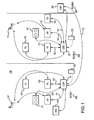
FIG. 1 depicts a sample operating environment for a centralized control unit. -
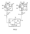
FIG. 2 is a schematic representation of control boxes that may be employed in the sample operating environment illustrated inFIG. 1 . -
FIG. 3 is an example of a table that may be employed by the embodiments described herein. -
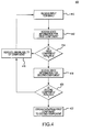
FIG. 4 is a flowchart illustrating an example of a method for transmitting a data signal between multiple components. -
FIG. 5 is a flowchart illustrating an example of a method for processing a command at a central control box. - Generally, embodiments described herein disclose systems, apparatuses and methods for controlling multiple components using a single, centralized device (referred to herein as a "control box"). The control box may be connected to various components in a home, office or other locale and configured to control these components. As an example, the control box may be configured to control various functions of the components and receive state information regarding the components. Thus, through the control box, a user may control the components connected thereto, as well as facilitate interaction between the components. This may be true even when the components are located in different rooms from one another and/or in different rooms from the control box.
- The control box may also be configured to relay data, such as audio and/or video, from one component to another. That is, the control box may accept data from one component and transfer it for output on another component. This may be facilitated through the use of localized control boxes that may act to route data to all devices connected thereto. These local control boxes may also accept commands from a remote control and implement those commands to control attached components, or may relay the commands to the centralized control box. Essentially, each local control box may be connected to a central control box; the central control box may coordinate and relay data between local control boxes and, thus, between components connected to local control boxes. The central control box may also act to relay commands from a remote between local control boxes and/or associated components.
- The terms "electronic component" and "component" are used interchangeably herein. Both terms refer to a device that is configured to perform certain functionality in response to the receipt of a command; the command may be inputted into the component directly, through a remote control or via a network connection. Accordingly, devices such as televisions, television receivers, audio equipment, appropriately-configured household appliances and fixtures, and so on may all be considered components. Further, the control boxes themselves may be components.
- This document also refers to "state information." As used herein, "state information" discloses the operating state and status of a component. State information may include power status, current output, current input, active processing routine (such as an audio and/or video format of an output), battery life remaining, and so on.
- It should be noted that this document discusses functionality of embodiments with respect to "television receivers." A television receiver, as described herein, is intended to encompass other forms of signal receiving components, such as set-top boxes, cable boxes, tuning circuitry within a television or receiver, and so on. Accordingly, the term "television receiver" is one of convenience and not limitation. Likewise, references to a satellite transmission system may be replaced with cable transmission systems, over the air (terrestrial) broadcasts, data transmissions across a wired or wireless network, including networks such as the Internet, intranets, and so on, without departing from the spirit or scope of this disclosure. Thus, one should understand the embodiments encompass the use of any of the foregoing networks in lieu of the satellite network used to illustrate certain embodiments herein.
-
FIG. 1 depicts asample environment 100 in which a user may employ a sample centralized control unit. Various components may be located in theenvironment 100 ofFIG. 1 , such as, but not limited to, one ormore televisions more television receivers more audio receivers player 102 and/or a compact disc ("CD")player 104, one ormore speakers local control boxes remote control devices FIG. 1 , may be in different rooms and/or on different floors, different physical locations or any combination thereof. - In this example, the
environment 100 includes threerooms rooms local control box room 199 may include a firstlocal control box 101 that is connected to a first set of components, while asecond room 299 may include a secondlocal control box 201 that is connected to a second set of components. In addition, athird room 399 may include acentralized control box 301 that is connected to the first and secondlocal control boxes second control boxes - Additionally, the
local control boxes more remotes remotes local control boxes television receivers audio receivers DVD player 102,CD player 104 and/ortelevisions local control boxes remotes local control boxes local control boxes - Commands may be transmitted to components either directly or via the
local control boxes local control box local control box remotes local control box local control box local control boxes boxes boxes remotes environment 100 but may not be connected to either of thelocal control boxes - The
remotes remotes local control boxes remotes local control boxes environment 100 through any suitable means, such as an IR signal, RF signal, wireless Internet Protocol ("IP") connection, cellular signal, WiMax signal, combinations thereof, and so on. - Additionally, the
remotes local control box local control boxes environment 100 that are located in the same room as the remote such as a television, a stereo, a VCR, a DVD player and so on, or in another room or on another floor. - The
local control boxes network 121, whether wired or wireless. Further, acentral control box 301 may be connected to one or both of thelocal control boxes FIG. 1 , thecentral control box 301 may be located in a separate room from the local control boxes. However, in other embodiments, thecentral control box 301 may be located in the same room as either or both of thelocal control boxes - As previously mentioned,
television receivers local control boxes television receivers content provider 107, such as a cable television provider, a broadcast television provider, a satellite television provider and so on. Eachtelevision receiver television receivers remotes local control box - As shown in
FIG. 1 , thetelevision receivers television receiver more televisions audio receivers television receiver local control box environment 100, such as through anetwork 121. - In addition,
multiple televisions environment 100. As shown inFIG. 1 , thetelevisions television local control box local control box televisions more television receivers local control box multiple televisions - One or more
audio receivers environment 100. As shown inFIG. 1 , theaudio receivers audio receiver local control box environment 100, such as through anetwork 121. Theaudio receivers remotes local control box - Other components located in the
environment 100 may also be connected to one or multiplelocal control boxes DVD player 102,CD player 104, and/orspeakers 111 121 may each be connected to a respectivelocal control box local control box audio receivers - The components located in the
environment 100 ofFIG. 1 are provided for explanatory purposes only. Further, a computing system (not shown) may be located in theenvironment 100. The computing system may be in the same room or may be in a different room than thelocal control boxes local control boxes - In
FIG. 1 , thelocal control boxes television receivers televisions audio receivers speakers DVD player 102, and/orCD player 104. Communications between thelocal control boxes - In one example, the
local control boxes local control boxes local control boxes local control boxes - The
local control boxes environment 100 wirelessly, through a wired connection, or through a combination thereof. Thelocal control boxes environment 100 throughremotes FIG. 1 , thelocal control boxes televisions audio receivers television receivers DVD player 102, andCD player 104 based on control commands transmitted by theremotes local control boxes remotes local control boxes remotes local control boxes local control boxes remotes - The
remotes local control boxes remotes - The
centralized control box 301 may be operationally, directly, indirectly, functionally or otherwise connected to thelocal control boxes central control box 301 and thelocal control boxes local control boxes central control box 301 so that thecentral control box 301 may process and store the state information. The state information may be passed from thelocal control boxes central control box 301 through a back-channel, or through any two-way communication link, including a Q-link, Viera cast, or HDMI. - The
television receivers televisions televisions television receivers - The
audio receivers television receivers speakers 111, and any other input or output components, such as aDVD player 102 andCD player 104. Communications between theaudio receivers television receivers televisions - A schematic representation of a control box system is illustrated in
FIG. 2 . As shown inFIG. 2 , eachlocal control box receiver remotes transmitter local control boxes processor memory device FIG. 2 depicts thelocal control boxes local control boxes - The inputs 160(1)-160(n), 260(1)-260(n) of the
local control boxes local control boxes - The outputs 161(1)-161(n), 261(1)-261(n) of the
local control boxes local control boxes local control boxes - The
processors local control boxes local control boxes transmitter storage devices local control boxes storage devices - The
processors local control boxes remote control devices local control boxes - The
central control box 301 may utilize a two-way communication link 121 to communicate with each of thelocal control boxes processor 352, amemory device 354, a receiver 350 configured to receive input commands, and one ormore transmitters 370. The input commands may be initiated by a user, for example, through a remote control, one of thelocal control boxes local control boxes central control box 301, and may further be configured to transmit the video and audio data signals received by thelocal control boxes transmitter 370. Additionally, thetransmitters 370 may be configured to transmit control commands from thecentral control box 301 to thelocal control boxes - In one embodiment, the
processor 352 of thecentral control box 301 may facilitate routing or streaming data, including audio and/or video data, between thelocal control boxes central control box 301, in conjunction with thelocal control boxes local control boxes FIG. 1 as an example, a video signal received from thetelevision receiver 103 located in thefirst room 199 may be transmitted to thetelevision 115 in thesecond room 299, even though the receiver and television are not directly connected to one another. The embodiment may route data to thelocal control box 101 connected to thetelevision receiver 103, from thelocal control box 101 to thecentral control box 301, from thecentral control box 301 to thelocal control box 201 connected to thetelevision 115 and ultimately to the television. As another example, an audio signal received from theCD player 104 in thesecond room 299 may be played byspeakers 111 in thefirst room 199 by routing the signal from theCD player 104 to thelocal control box 201, then to thecentral control box 301, from thecentral control box 301 to thelocal control box 101,and ultimately to thespeakers 111. One example of a method for routing data signals between two components in an environment using a control box is discussed in detail with respect toFIG. 4 . - Returning to
Fig. 2 , theprocessor 352 of thecentral control box 301 may further be configured to process the control commands transmitted by theremote control devices local control boxes 101, 201). In one embodiment, eachremote control local control boxes central control box 301. Turning off the components connected to thelocal control boxes FIG. 5 provides an example of the interaction between a remote, the central control box and a component and is discussed below. Similarly, thecentral control box 301 and/orlocal control boxes central control box 301 to turn off all of the components when the user typically goes to sleep or goes to work to avoid wasting power when the user does not intend to operate any of the components. In some embodiments, components may be plugged into thelocal control boxes - Additionally, the
processor 152 of thecentral control box 301 may be connected to astorage device 354. Thestorage device 354 may be volatile memory, such as static RAM or dynamic RAM, or non-volatile memory, such as read-only memory, flash memory, or a magnetic computer storage device (e.g. hard disks, floppy discs, etc.). Thestorage device 154 may be configured to store state information relating to the components connected to thelocal control boxes - One example of a table that may be employed by the control boxes described herein is illustrated in
FIG. 3 . The table may include alist 300 of components that are connected to thelocal control boxes component entry 304 andstate information 302 for that component. Each component may be denoted by a suitable unique identifier. The exact identifier may vary between embodiments but may include a generic name for the component, a numerical identifier, a brand name of the component, a component serial and/or model number, or any other identifier that may allow the user to identify the associated component. As appropriate, the table 300 may be periodically updated or may be updated only when a change in state of a component occurs so that the state information for each component is current. - As mentioned above, the stored
state information 302 may include whether a connected component is on or off, disconnected, whether the component is currently in use, an operating state of the component, whether the component is in an idle state, and so forth. In this example, the table 300 inFIG. 3 indicates that a DVD player, television receiver, and television are all in an idle state, and that an audio receiver is off. State information may be received by thecentral control box 301 from alocal control box - Additionally, the state information shown on the table 300 may include information regarding the input signals currently being transmitted to a particular component. The specificity of the information may vary according to different embodiments of the present disclosure. For example, the table 300 shown in
FIG. 3 indicates that thetelevision 1 is currently receiving an input signal from thetelevision receiver 2, and that the audio-receiver 2 is currently receiving an input signal from the CD player. As shown inFIG. 3 , the table 300 may further include information regarding the output signals being transmitted by a particular component. For example, the table 300 may indicate that the video signal from thetelevision receiver 2 is being transmitted to thetelevision 1, and that the audio signal from the CD player is being transmitted to theaudio receiver 2. - Other embodiments may employ a simplified version of the table 300 illustrated in
FIG. 3 . For example, the state information may be limited to idle, busy, on, off, and/or disconnected states, while omitting any information relating to the input signals received by a component or the output signals transmitted by a component. Additionally, some embodiments may be more detailed than the information provided by the table 300 inFIG. 3 . For example, the table may indicate which channel a particular television receiver is currently tuned to, including program information, which radio station a particular audio receiver is currently tuned to, including any associated program information, the CD or song being player by the CD player, the movie being played by a DVD player, and so on. - In one embodiment, all of the possible states for each component connected to the local control boxes may be stored in a
database 301 at thestorage device 354 of the central control box and/or at thestorage devices local control boxes - The
central control box 301, in conjunction with thelocal control boxes central control box 301 may receive state information from the components connected to thelocal control boxes control box 301 turns off the components may vary, and may be preprogrammed by the user. Thus, as an example, if a user finishes watching television and forgets to turn off the television receiver associated with the television, thecentral control box 301 may determine that the television receiver is in an idle state and turn it off after a preset period of time. - In some embodiments, a user may access the information in the table 300. The information may be presented to the user via any display device that is connected to the
local control boxes local control boxes central control box 301. For example, with respect to the embodiment shown inFIG. 1 , the information may be displayed on one of thetelevisions local control boxes control boxes central control box 301 may transmit state information for that component to a display in the room occupied by the user. Since the central control box in aware of the user's room (insofar as the command is received from a particularlocal control box - In other embodiments, only some of the information from the table 300 may be presented to the user. For example, the
control boxes control boxes control boxes -
FIG. 4 is a flowchart depicting operations of an embodiment of amethod 400 for routing data signals between components. The method shown inFig. 4 may be executed by one or more local control boxes, a central control box or a combination thereof. - In the operation of
block 410, a control box may receive an input command from a remote. For example, the input command may be initiated a user and may identify both a source and destination component. In the operation ofblock 412, the control box may access the state information for the first component. The state information may be stored in memory at the control box in a table, as described above, and may include on, off, disconnected, busy and/or idle states. The state information may be received via inputs to the control box, such as through a two-way communication link between the control box and the component. The link may be a Q-link, HDMI connection, a back-channel, a network as discussed with respect toFig. 1 , and so forth. In some embodiments, a local control box may monitor the state information for components attached thereto and relay this information to the central control box. In yet other embodiments, the central control box may set the state information for a component based on a received command. Thus, if the control box receives a command to turn off a component, it may update the table to indicate the component is off. - In the operation of
block 414, the control box may determine whether the first component is available based on the information stored in the table. For example, the control box may access the table to determine whether the first component is currently in use, idle, off, or disconnected. Continuing the example, the table may indicate that the first component is in an unavailable state if the first component is disconnected, inaccessible or currently streaming data to another component. If the component is unavailable, then inoperation 416, the control box may indicate that the first component is unavailable. As discussed above, this may be accomplished by displaying the state information of the first component to the user via a display device, or indicating the unavailability of the first component using a sound. - If, in the operation of
block 414, the control box determines that the first component is available (for example, if the table indicates that the first component is available) then inoperation 418, the control box will access the state information for the second component. In one embodiment, if the table indicates that the first component is off, then the control box may transmit a control command to turn on the first component, and accordingly, update the status of the component to an "idle" or available state. - In the operation of
block 420, the control box may determine whether the second component is available based on the information stored in the table. The procedures for obtaining the status of the second component are similar to those described above with respect to the first component inoperation 414. If, in the operation ofblock 420, the table indicates that the first component is in an unavailable state, then, inoperation 416, the control box may indicate that the second component is unavailable. As discussed above, this may be accomplished by displaying the state information of the first component to the user via a display device, or indicating the unavailability of the first component using a sound. - If, in the operation of
block 420, the control box determines that the second component is available, then, inoperation 422, the control box will stream data from the first component to the second component. As discussed above, this may be accomplished using a processing device in the central control box, which may act as a network switch to route the data signal output by the first component to an input of the second component. The signal may be an audio and/or video signal, depending on the type of signal that is output by the first component. -
FIG. 5 is a flowchart depicting a method for processing a command at a central control box. The command may be initiated by a user through, for example, a remote control or direct input into a local control box (if applicable). - In the operation of
block 500, a control box may receive an input command. For example, the input command may be initiated a user and may identify both a source and a destination component, or multiple source and/or destination components. In the operation ofblock 510, the control box may determine the components involved in the command. For example, the control box may determine all of the source and destination components that that will transmit or receive data signals. In one embodiment, a list or a table of all of the components connected to the central control box and/or to local control boxes connected to the central control box may be stored in a memory of the central control box of the local control boxes, and the source and destination components may be determined from the list. Thelist 300 shown inFIG. 3 may be used for this purpose. - After determining the components involved in the command, in the operation of
block 515, the control box may retrieve state information for some or all of the components involved in the command. Continuing the example, the table may indicate that the component is in an unavailable state if the first component is disconnected, inaccessible or currently streaming data to another component. The state information may be received via inputs to the central control box, such as through a two-way communication link between the local control box connected to the component and the central control box. In other embodiments, a local control box may monitor the state information for components attached thereto and relay this information to the central control box. In yet other embodiments, the central control box may set the state information for a component based on a received command. - In the operation of
block 525, the central control box may determine the location of the components identified by the input command. In one embodiment, the central control box may determine the location of the components with respect to a local control box that is directly or indirectly connected to some or all of the components. For example, the local control boxes may transmit information identifying the components that are connected to each of the local control boxes to the central control box, and the central control box may store this information in memory. In another embodiment, the central control box may be directly or indirectly connected to some or all of the components, and the central control box may thus maintain location information from the components. - In the operation of
block 530, the central control box may create a command that will be transmitted to the component. The command may include, for example, a command to transmit an audio or data signal from the source component to the destination component, or a command to turn on or turn off the component. In one embodiment, this operation may include reformatting the command received inoperation 500 with any appropriate IR or RF signals for the component. - In the operation of
block 535, the central control box may transmit the command to the local control box connected to the component (if such a local control box exists). In one example, the command will be relayed through the local control box and instruct the component to stream data to a destination component or to turn on. As discussed above, the data from the component may be transmitted by the local control box to the central control box, which may route the data signal output by the first component to the local control boxes connected with the destination components. The signal may be an audio and/or video signal, depending on the type of signal that is output by the first component. - In
operation 537, the control box may receive state information regarding the component. The state information may be transmitted from the local control box connected to the component to the central control box. In another embodiment, the state information may be transmitted directly from the component to the central control box. - In
operation 540, the control box may determine whether the component being controlled is the last component identified in the input command. For example, if the input command designates two components, such as a source component and a destination component, the last component may be the destination component. In another example, if the input command designates a source component and two or more destination components, the control box will recognize a component as the "last" component when it has received state information from all of the other components designated by the input command. - If, in
operation 540, the control box determines that the component being controlled is not the last designated component, then block 555 is executed and the control box will retrieve state information regarding the next component designated in the input command in the operation ofblock 515. After block 555, the embodiment executes blocks 515-537 for this next component. However, if the control box determines that the component being controlled is the last designated component inblock 540, then,operation 545 is executed and the control box may update the state of the components designated in the input command. For example, the last component may be a destination component that is now receiving a data signal from a source component, and the control box may update the states of the destination and source components to indicate the unavailability of these components. - Once the states of the destination and source components have been updated, the method may continue to block 550, where the process may end.
- Although the embodiments have been described with respect to particular apparatuses, configurations, components, systems and methods of operation, it will be appreciated that certain changes or modifications to the embodiments and/or their operations, as described herein, may be made without departing from the spirit or scope of the invention. Accordingly, the proper scope of the invention is defined by the appended claims. The various embodiments, operations, components and configurations disclosed herein are generally provided as examples rather than limiting in scope.
Claims (15)
- A central control box, comprising:a receiving element configured to receive an input command;a processor connected to the receiving element and configured to receive a first data signal from a first component, receive state information regarding a second component, and process the received input command based on the state information regarding the second component;a first transmitter connected to the processor and configured to transmit the first data signal; anda storage device connected to the processor and configured to store the state information regarding the second component.
- A central control box as claimed in claim 1, wherein the processor is further configured to update the state information stored by the storage device regarding the second component.
- A central control box as claimed in claim 1 or 2, wherein the first component is located in a different room than the second component.
- A central control box as claimed in claim 1, 2 or 3, wherein the first data signal is received from a first local control box connected to the first component and the state information is received from a second local control box connected to the second component.
- A central control box as claimed in claim 4, wherein the central control box further comprises a second transmitter connected to the processor and configured to transmit a control command to control a function of the first local control box.
- A central control box as claimed in claims 4 or 5, wherein the first transmitter is configured to transmit the first data signal from the first local control box to a second local control box.
- A central control box as claimed in any one of the preceding claims, wherein the state information regarding the second component includes whether the second component is available or unavailable to process the first data signal.
- A central control box as claimed in claim 7, wherein if the state information indicates that the second component is available to process the first data signal, the first transmitter transmits the first data signal from a first local control box connected to the first component to a second local control box connected to the second component.
- A central control box as claimed in claim 7 or 8, wherein if the state information indicates that the second component is unavailable to process the first data signal, the first transmitter does not transmit the first data signal.
- A central control box as claimed in claim 8, wherein the processor is configured to update the state information to indicate that the second component is unavailable to process the first data signal once the first data signal is transmitted from the first local control box to the second local control box.
- A central control box as claimed in any one of the preceding claims, wherein the input command is received from a first local control box connected to the central control box.
- A method for routing a first data signal between a first component and a second component, the method comprising:receiving an input command identifying the first component and the second component;receiving a first data signal output by the first component;retrieving state information regarding the second component; androuting the first data signal through a central control box based on the state information regarding the second component.
- A method as claimed in claim 12, further comprising storing the state information regarding the second component in a storage device and updating the state information regarding the second component once the first data signal has been routed through the central control box.
- A system for routing a data signal between two or more components, comprising:a first control box configured to receive a first data signal from a first component;a second control box operably connected to the first control box; anda third control box operably connected to the second control box and to a second component; whereinthe second control box is configured to transmit the first data signal from the first control box to the third control box;the third control box is configured to relay the first data signal to the second component;
andat least one of the first, second, and third control box is configured to receive and store state information regarding the second component. - A system as claimed in claim 14, wherein the second control box is configured to transmit the first data signal to the second component based on the state information regarding the second component.
Priority Applications (2)
| Application Number | Priority Date | Filing Date | Title |
|---|---|---|---|
| EP09180482.3A EP2348480B1 (en) | 2009-12-22 | 2009-12-22 | A method and system for control of electronic components |
| US12/974,614 US10198936B2 (en) | 2009-12-22 | 2010-12-21 | Control of electronic components |
Applications Claiming Priority (1)
| Application Number | Priority Date | Filing Date | Title |
|---|---|---|---|
| EP09180482.3A EP2348480B1 (en) | 2009-12-22 | 2009-12-22 | A method and system for control of electronic components |
Publications (2)
| Publication Number | Publication Date |
|---|---|
| EP2348480A1 true EP2348480A1 (en) | 2011-07-27 |
| EP2348480B1 EP2348480B1 (en) | 2017-04-26 |
Family
ID=42046187
Family Applications (1)
| Application Number | Title | Priority Date | Filing Date |
|---|---|---|---|
| EP09180482.3A Active EP2348480B1 (en) | 2009-12-22 | 2009-12-22 | A method and system for control of electronic components |
Country Status (2)
| Country | Link |
|---|---|
| US (1) | US10198936B2 (en) |
| EP (1) | EP2348480B1 (en) |
Families Citing this family (2)
| Publication number | Priority date | Publication date | Assignee | Title |
|---|---|---|---|---|
| DK2755299T3 (en) * | 2013-01-10 | 2018-09-17 | Timotion Technology Co Ltd | Energy-saving remote control device and energy-saving manual control device |
| ITUB20153445A1 (en) * | 2015-09-07 | 2017-03-07 | Fincantieri Spa | SYSTEM AND METHOD OF CHECKING INFORMATION REPRESENTATIVE OF USE BY ONE OR MORE USERS OF ONE OR MORE HABITABLE ENVIRONMENTS OF A SHIP |
Citations (3)
| Publication number | Priority date | Publication date | Assignee | Title |
|---|---|---|---|---|
| WO2002054676A1 (en) * | 2000-12-29 | 2002-07-11 | BSH Bosch und Siemens Hausgeräte GmbH | Method and device for controlling domestic appliances |
| WO2006035472A2 (en) * | 2004-09-29 | 2006-04-06 | Matrix S.R.L. | Domotic system provided with centralized controlling and managing hardware and software for remote management of domestic appliances, apparatuses, installations, devices and machines existing in a house |
| WO2007135695A1 (en) * | 2006-05-18 | 2007-11-29 | Roberto Ragazzi | A control device for domotic applications |
Family Cites Families (11)
| Publication number | Priority date | Publication date | Assignee | Title |
|---|---|---|---|---|
| US7716077B1 (en) * | 1999-11-22 | 2010-05-11 | Accenture Global Services Gmbh | Scheduling and planning maintenance and service in a network-based supply chain environment |
| US6671818B1 (en) * | 1999-11-22 | 2003-12-30 | Accenture Llp | Problem isolation through translating and filtering events into a standard object format in a network based supply chain |
| US7130807B1 (en) * | 1999-11-22 | 2006-10-31 | Accenture Llp | Technology sharing during demand and supply planning in a network-based supply chain environment |
| US6678740B1 (en) * | 2000-01-14 | 2004-01-13 | Terayon Communication Systems, Inc. | Process carried out by a gateway in a home network to receive video-on-demand and other requested programs and services |
| US7689510B2 (en) * | 2000-09-07 | 2010-03-30 | Sonic Solutions | Methods and system for use in network management of content |
| US7933945B2 (en) * | 2002-06-27 | 2011-04-26 | Openpeak Inc. | Method, system, and computer program product for managing controlled residential or non-residential environments |
| US20070132733A1 (en) * | 2004-06-08 | 2007-06-14 | Pranil Ram | Computer Apparatus with added functionality |
| US20060072487A1 (en) * | 2004-09-22 | 2006-04-06 | Howard John S | Power conservation for a wireless device |
| US7305278B2 (en) * | 2004-11-15 | 2007-12-04 | International Business Machines Corporation | Enterprise factory control method and system |
| US9233301B2 (en) * | 2006-09-07 | 2016-01-12 | Rateze Remote Mgmt Llc | Control of data presentation from multiple sources using a wireless home entertainment hub |
| US8494145B2 (en) * | 2006-12-14 | 2013-07-23 | Motorola Mobility Llc | Method and system for managing a call request in a network |
-
2009
- 2009-12-22 EP EP09180482.3A patent/EP2348480B1/en active Active
-
2010
- 2010-12-21 US US12/974,614 patent/US10198936B2/en active Active
Patent Citations (3)
| Publication number | Priority date | Publication date | Assignee | Title |
|---|---|---|---|---|
| WO2002054676A1 (en) * | 2000-12-29 | 2002-07-11 | BSH Bosch und Siemens Hausgeräte GmbH | Method and device for controlling domestic appliances |
| WO2006035472A2 (en) * | 2004-09-29 | 2006-04-06 | Matrix S.R.L. | Domotic system provided with centralized controlling and managing hardware and software for remote management of domestic appliances, apparatuses, installations, devices and machines existing in a house |
| WO2007135695A1 (en) * | 2006-05-18 | 2007-11-29 | Roberto Ragazzi | A control device for domotic applications |
Also Published As
| Publication number | Publication date |
|---|---|
| US10198936B2 (en) | 2019-02-05 |
| US20110153032A1 (en) | 2011-06-23 |
| EP2348480B1 (en) | 2017-04-26 |
Similar Documents
| Publication | Publication Date | Title |
|---|---|---|
| JP5501444B2 (en) | Sink device, source device, and wireless transmission system | |
| US10404801B2 (en) | Reconfiguring remote controls for different devices in a network | |
| US8412355B2 (en) | System for transferring controlling authority of a device | |
| US7924168B2 (en) | Remote control system, remote commander and remote control method, apparatus to be remotely controlled, and computer system | |
| US7746245B2 (en) | Integrated remote control system | |
| US8903563B2 (en) | Control device and method thereof | |
| US9401084B2 (en) | Assisting use of control devices with different electronic devices | |
| EP2791756B1 (en) | Apparatus, systems and methods for modifying operating states based on monitored hdmi cec communications | |
| US20090054003A1 (en) | Wireless video system controlled according to control command of external device, wireless video receiver, and method for controlling wireless video system | |
| JP2010166481A (en) | Sink device and radio transmission system | |
| US20100013660A1 (en) | Pairing method and control device therefor | |
| US9050531B2 (en) | Assisting use of control devices with different content players in a network | |
| US20110085089A1 (en) | Apparatus and method for remote control in home network | |
| US10198936B2 (en) | Control of electronic components | |
| JP4263203B2 (en) | Broadcast viewing system | |
| JP5044671B2 (en) | Source equipment | |
| JP5091972B2 (en) | Sink device and wireless transmission system | |
| JP5044672B2 (en) | Sink device and source device | |
| JP2007174300A (en) | Setting data changing system, remote control device and setting data changing method | |
| KR101113275B1 (en) | Broadcasting support device having an operation command learning function and its operation command learning method | |
| JP2010166609A (en) | Source device and wireless transmission system | |
| CN1972201A (en) | Remote control system, remote commander, remote control operating method, apparatus to be controlled in remote control | |
| KR101020039B1 (en) | Multi Zone Media Distribution Control System | |
| KR20130014982A (en) | Method for paring in remote controllers | |
| JP2007174290A (en) | Setting data changing system, remote control device and setting data changing method |
Legal Events
| Date | Code | Title | Description |
|---|---|---|---|
| PUAI | Public reference made under article 153(3) epc to a published international application that has entered the european phase |
Free format text: ORIGINAL CODE: 0009012 |
|
| AK | Designated contracting states |
Kind code of ref document: A1 Designated state(s): AT BE BG CH CY CZ DE DK EE ES FI FR GB GR HR HU IE IS IT LI LT LU LV MC MK MT NL NO PL PT RO SE SI SK SM TR |
|
| AX | Request for extension of the european patent |
Extension state: AL BA RS |
|
| 17P | Request for examination filed |
Effective date: 20120126 |
|
| 17Q | First examination report despatched |
Effective date: 20120705 |
|
| RAP1 | Party data changed (applicant data changed or rights of an application transferred) |
Owner name: ECHOSTAR TECHNOLOGIES L.L.C. |
|
| REG | Reference to a national code |
Ref country code: DE Ref legal event code: R079 Ref document number: 602009045666 Country of ref document: DE Free format text: PREVIOUS MAIN CLASS: G06Q0099000000 Ipc: G05B0019000000 |
|
| GRAP | Despatch of communication of intention to grant a patent |
Free format text: ORIGINAL CODE: EPIDOSNIGR1 |
|
| RIC1 | Information provided on ipc code assigned before grant |
Ipc: G08B 1/00 20060101ALI20170111BHEP Ipc: G05B 19/00 20060101AFI20170111BHEP Ipc: G06Q 10/06 20120101ALI20170111BHEP |
|
| INTG | Intention to grant announced |
Effective date: 20170206 |
|
| GRAS | Grant fee paid |
Free format text: ORIGINAL CODE: EPIDOSNIGR3 |
|
| GRAA | (expected) grant |
Free format text: ORIGINAL CODE: 0009210 |
|
| AK | Designated contracting states |
Kind code of ref document: B1 Designated state(s): AT BE BG CH CY CZ DE DK EE ES FI FR GB GR HR HU IE IS IT LI LT LU LV MC MK MT NL NO PL PT RO SE SI SK SM TR |
|
| REG | Reference to a national code |
Ref country code: GB Ref legal event code: FG4D |
|
| REG | Reference to a national code |
Ref country code: CH Ref legal event code: EP |
|
| REG | Reference to a national code |
Ref country code: AT Ref legal event code: REF Ref document number: 888395 Country of ref document: AT Kind code of ref document: T Effective date: 20170515 |
|
| REG | Reference to a national code |
Ref country code: IE Ref legal event code: FG4D |
|
| REG | Reference to a national code |
Ref country code: DE Ref legal event code: R096 Ref document number: 602009045666 Country of ref document: DE |
|
| REG | Reference to a national code |
Ref country code: NL Ref legal event code: FP |
|
| REG | Reference to a national code |
Ref country code: LT Ref legal event code: MG4D |
|
| REG | Reference to a national code |
Ref country code: AT Ref legal event code: MK05 Ref document number: 888395 Country of ref document: AT Kind code of ref document: T Effective date: 20170426 |
|
| PG25 | Lapsed in a contracting state [announced via postgrant information from national office to epo] |
Ref country code: FI Free format text: LAPSE BECAUSE OF FAILURE TO SUBMIT A TRANSLATION OF THE DESCRIPTION OR TO PAY THE FEE WITHIN THE PRESCRIBED TIME-LIMIT Effective date: 20170426 Ref country code: LT Free format text: LAPSE BECAUSE OF FAILURE TO SUBMIT A TRANSLATION OF THE DESCRIPTION OR TO PAY THE FEE WITHIN THE PRESCRIBED TIME-LIMIT Effective date: 20170426 Ref country code: GR Free format text: LAPSE BECAUSE OF FAILURE TO SUBMIT A TRANSLATION OF THE DESCRIPTION OR TO PAY THE FEE WITHIN THE PRESCRIBED TIME-LIMIT Effective date: 20170727 Ref country code: ES Free format text: LAPSE BECAUSE OF FAILURE TO SUBMIT A TRANSLATION OF THE DESCRIPTION OR TO PAY THE FEE WITHIN THE PRESCRIBED TIME-LIMIT Effective date: 20170426 Ref country code: NO Free format text: LAPSE BECAUSE OF FAILURE TO SUBMIT A TRANSLATION OF THE DESCRIPTION OR TO PAY THE FEE WITHIN THE PRESCRIBED TIME-LIMIT Effective date: 20170726 Ref country code: HR Free format text: LAPSE BECAUSE OF FAILURE TO SUBMIT A TRANSLATION OF THE DESCRIPTION OR TO PAY THE FEE WITHIN THE PRESCRIBED TIME-LIMIT Effective date: 20170426 Ref country code: AT Free format text: LAPSE BECAUSE OF FAILURE TO SUBMIT A TRANSLATION OF THE DESCRIPTION OR TO PAY THE FEE WITHIN THE PRESCRIBED TIME-LIMIT Effective date: 20170426 |
|
| REG | Reference to a national code |
Ref country code: FR Ref legal event code: PLFP Year of fee payment: 9 |
|
| PG25 | Lapsed in a contracting state [announced via postgrant information from national office to epo] |
Ref country code: LV Free format text: LAPSE BECAUSE OF FAILURE TO SUBMIT A TRANSLATION OF THE DESCRIPTION OR TO PAY THE FEE WITHIN THE PRESCRIBED TIME-LIMIT Effective date: 20170426 Ref country code: IS Free format text: LAPSE BECAUSE OF FAILURE TO SUBMIT A TRANSLATION OF THE DESCRIPTION OR TO PAY THE FEE WITHIN THE PRESCRIBED TIME-LIMIT Effective date: 20170826 Ref country code: PL Free format text: LAPSE BECAUSE OF FAILURE TO SUBMIT A TRANSLATION OF THE DESCRIPTION OR TO PAY THE FEE WITHIN THE PRESCRIBED TIME-LIMIT Effective date: 20170426 Ref country code: SE Free format text: LAPSE BECAUSE OF FAILURE TO SUBMIT A TRANSLATION OF THE DESCRIPTION OR TO PAY THE FEE WITHIN THE PRESCRIBED TIME-LIMIT Effective date: 20170426 Ref country code: BG Free format text: LAPSE BECAUSE OF FAILURE TO SUBMIT A TRANSLATION OF THE DESCRIPTION OR TO PAY THE FEE WITHIN THE PRESCRIBED TIME-LIMIT Effective date: 20170726 |
|
| REG | Reference to a national code |
Ref country code: DE Ref legal event code: R097 Ref document number: 602009045666 Country of ref document: DE |
|
| PG25 | Lapsed in a contracting state [announced via postgrant information from national office to epo] |
Ref country code: DK Free format text: LAPSE BECAUSE OF FAILURE TO SUBMIT A TRANSLATION OF THE DESCRIPTION OR TO PAY THE FEE WITHIN THE PRESCRIBED TIME-LIMIT Effective date: 20170426 Ref country code: CZ Free format text: LAPSE BECAUSE OF FAILURE TO SUBMIT A TRANSLATION OF THE DESCRIPTION OR TO PAY THE FEE WITHIN THE PRESCRIBED TIME-LIMIT Effective date: 20170426 Ref country code: SK Free format text: LAPSE BECAUSE OF FAILURE TO SUBMIT A TRANSLATION OF THE DESCRIPTION OR TO PAY THE FEE WITHIN THE PRESCRIBED TIME-LIMIT Effective date: 20170426 Ref country code: EE Free format text: LAPSE BECAUSE OF FAILURE TO SUBMIT A TRANSLATION OF THE DESCRIPTION OR TO PAY THE FEE WITHIN THE PRESCRIBED TIME-LIMIT Effective date: 20170426 Ref country code: RO Free format text: LAPSE BECAUSE OF FAILURE TO SUBMIT A TRANSLATION OF THE DESCRIPTION OR TO PAY THE FEE WITHIN THE PRESCRIBED TIME-LIMIT Effective date: 20170426 |
|
| PG25 | Lapsed in a contracting state [announced via postgrant information from national office to epo] |
Ref country code: SM Free format text: LAPSE BECAUSE OF FAILURE TO SUBMIT A TRANSLATION OF THE DESCRIPTION OR TO PAY THE FEE WITHIN THE PRESCRIBED TIME-LIMIT Effective date: 20170426 Ref country code: IT Free format text: LAPSE BECAUSE OF FAILURE TO SUBMIT A TRANSLATION OF THE DESCRIPTION OR TO PAY THE FEE WITHIN THE PRESCRIBED TIME-LIMIT Effective date: 20170426 |
|
| PLBE | No opposition filed within time limit |
Free format text: ORIGINAL CODE: 0009261 |
|
| STAA | Information on the status of an ep patent application or granted ep patent |
Free format text: STATUS: NO OPPOSITION FILED WITHIN TIME LIMIT |
|
| 26N | No opposition filed |
Effective date: 20180129 |
|
| PG25 | Lapsed in a contracting state [announced via postgrant information from national office to epo] |
Ref country code: SI Free format text: LAPSE BECAUSE OF FAILURE TO SUBMIT A TRANSLATION OF THE DESCRIPTION OR TO PAY THE FEE WITHIN THE PRESCRIBED TIME-LIMIT Effective date: 20170426 |
|
| REG | Reference to a national code |
Ref country code: CH Ref legal event code: PL |
|
| REG | Reference to a national code |
Ref country code: IE Ref legal event code: MM4A |
|
| PG25 | Lapsed in a contracting state [announced via postgrant information from national office to epo] |
Ref country code: LU Free format text: LAPSE BECAUSE OF NON-PAYMENT OF DUE FEES Effective date: 20171222 Ref country code: MT Free format text: LAPSE BECAUSE OF NON-PAYMENT OF DUE FEES Effective date: 20171222 |
|
| REG | Reference to a national code |
Ref country code: BE Ref legal event code: MM Effective date: 20171231 |
|
| PG25 | Lapsed in a contracting state [announced via postgrant information from national office to epo] |
Ref country code: IE Free format text: LAPSE BECAUSE OF NON-PAYMENT OF DUE FEES Effective date: 20171222 |
|
| PG25 | Lapsed in a contracting state [announced via postgrant information from national office to epo] |
Ref country code: BE Free format text: LAPSE BECAUSE OF NON-PAYMENT OF DUE FEES Effective date: 20171231 Ref country code: LI Free format text: LAPSE BECAUSE OF NON-PAYMENT OF DUE FEES Effective date: 20171231 Ref country code: CH Free format text: LAPSE BECAUSE OF NON-PAYMENT OF DUE FEES Effective date: 20171231 |
|
| PG25 | Lapsed in a contracting state [announced via postgrant information from national office to epo] |
Ref country code: HU Free format text: LAPSE BECAUSE OF FAILURE TO SUBMIT A TRANSLATION OF THE DESCRIPTION OR TO PAY THE FEE WITHIN THE PRESCRIBED TIME-LIMIT; INVALID AB INITIO Effective date: 20091222 Ref country code: MC Free format text: LAPSE BECAUSE OF FAILURE TO SUBMIT A TRANSLATION OF THE DESCRIPTION OR TO PAY THE FEE WITHIN THE PRESCRIBED TIME-LIMIT Effective date: 20170426 |
|
| REG | Reference to a national code |
Ref country code: DE Ref legal event code: R082 Ref document number: 602009045666 Country of ref document: DE Representative=s name: HERNANDEZ, YORCK, DIPL.-ING., DE Ref country code: DE Ref legal event code: R081 Ref document number: 602009045666 Country of ref document: DE Owner name: DISH TECHNOLOGIES L.L.C., ENGLEWOOD, US Free format text: FORMER OWNER: ECHOSTAR TECHNOLOGIES L.L.C., ENGLEWOOD, COL., US |
|
| REG | Reference to a national code |
Ref country code: NL Ref legal event code: HC Owner name: DISH TECHNOLOGIES L.L.C.; US Free format text: DETAILS ASSIGNMENT: CHANGE OF OWNER(S), CHANGE OF OWNER(S) NAME; FORMER OWNER NAME: ECHOSTAR TECHNOLOGIES L.L.C. Effective date: 20190829 |
|
| PG25 | Lapsed in a contracting state [announced via postgrant information from national office to epo] |
Ref country code: CY Free format text: LAPSE BECAUSE OF NON-PAYMENT OF DUE FEES Effective date: 20170426 |
|
| PG25 | Lapsed in a contracting state [announced via postgrant information from national office to epo] |
Ref country code: MK Free format text: LAPSE BECAUSE OF FAILURE TO SUBMIT A TRANSLATION OF THE DESCRIPTION OR TO PAY THE FEE WITHIN THE PRESCRIBED TIME-LIMIT Effective date: 20170426 |
|
| PG25 | Lapsed in a contracting state [announced via postgrant information from national office to epo] |
Ref country code: TR Free format text: LAPSE BECAUSE OF FAILURE TO SUBMIT A TRANSLATION OF THE DESCRIPTION OR TO PAY THE FEE WITHIN THE PRESCRIBED TIME-LIMIT Effective date: 20170426 |
|
| PG25 | Lapsed in a contracting state [announced via postgrant information from national office to epo] |
Ref country code: PT Free format text: LAPSE BECAUSE OF FAILURE TO SUBMIT A TRANSLATION OF THE DESCRIPTION OR TO PAY THE FEE WITHIN THE PRESCRIBED TIME-LIMIT Effective date: 20170426 |
|
| P01 | Opt-out of the competence of the unified patent court (upc) registered |
Effective date: 20230521 |
|
| PGFP | Annual fee paid to national office [announced via postgrant information from national office to epo] |
Ref country code: NL Payment date: 20251003 Year of fee payment: 17 |
|
| PGFP | Annual fee paid to national office [announced via postgrant information from national office to epo] |
Ref country code: DE Payment date: 20250930 Year of fee payment: 17 |
|
| PGFP | Annual fee paid to national office [announced via postgrant information from national office to epo] |
Ref country code: GB Payment date: 20251001 Year of fee payment: 17 |
|
| PGFP | Annual fee paid to national office [announced via postgrant information from national office to epo] |
Ref country code: FR Payment date: 20251110 Year of fee payment: 17 |