EP2348223A1 - Power transmission device - Google Patents
Power transmission device Download PDFInfo
- Publication number
- EP2348223A1 EP2348223A1 EP08878124A EP08878124A EP2348223A1 EP 2348223 A1 EP2348223 A1 EP 2348223A1 EP 08878124 A EP08878124 A EP 08878124A EP 08878124 A EP08878124 A EP 08878124A EP 2348223 A1 EP2348223 A1 EP 2348223A1
- Authority
- EP
- European Patent Office
- Prior art keywords
- shaft member
- shaft
- electromagnetic wave
- space
- bearing
- Prior art date
- Legal status (The legal status is an assumption and is not a legal conclusion. Google has not performed a legal analysis and makes no representation as to the accuracy of the status listed.)
- Granted
Links
Images


Classifications
-
- H—ELECTRICITY
- H05—ELECTRIC TECHNIQUES NOT OTHERWISE PROVIDED FOR
- H05K—PRINTED CIRCUITS; CASINGS OR CONSTRUCTIONAL DETAILS OF ELECTRIC APPARATUS; MANUFACTURE OF ASSEMBLAGES OF ELECTRICAL COMPONENTS
- H05K9/00—Screening of apparatus or components against electric or magnetic fields
- H05K9/0007—Casings
- H05K9/0018—Casings with provisions to reduce aperture leakages in walls, e.g. terminals, connectors, cables
-
- E—FIXED CONSTRUCTIONS
- E04—BUILDING
- E04H—BUILDINGS OR LIKE STRUCTURES FOR PARTICULAR PURPOSES; SWIMMING OR SPLASH BATHS OR POOLS; MASTS; FENCING; TENTS OR CANOPIES, IN GENERAL
- E04H5/00—Buildings or groups of buildings for industrial or agricultural purposes
- E04H5/02—Buildings or groups of buildings for industrial purposes, e.g. for power-plants or factories
-
- F—MECHANICAL ENGINEERING; LIGHTING; HEATING; WEAPONS; BLASTING
- F16—ENGINEERING ELEMENTS AND UNITS; GENERAL MEASURES FOR PRODUCING AND MAINTAINING EFFECTIVE FUNCTIONING OF MACHINES OR INSTALLATIONS; THERMAL INSULATION IN GENERAL
- F16D—COUPLINGS FOR TRANSMITTING ROTATION; CLUTCHES; BRAKES
- F16D1/00—Couplings for rigidly connecting two coaxial shafts or other movable machine elements
- F16D1/02—Couplings for rigidly connecting two coaxial shafts or other movable machine elements for connecting two abutting shafts or the like
-
- F—MECHANICAL ENGINEERING; LIGHTING; HEATING; WEAPONS; BLASTING
- F16—ENGINEERING ELEMENTS AND UNITS; GENERAL MEASURES FOR PRODUCING AND MAINTAINING EFFECTIVE FUNCTIONING OF MACHINES OR INSTALLATIONS; THERMAL INSULATION IN GENERAL
- F16D—COUPLINGS FOR TRANSMITTING ROTATION; CLUTCHES; BRAKES
- F16D1/00—Couplings for rigidly connecting two coaxial shafts or other movable machine elements
- F16D1/02—Couplings for rigidly connecting two coaxial shafts or other movable machine elements for connecting two abutting shafts or the like
- F16D1/033—Couplings for rigidly connecting two coaxial shafts or other movable machine elements for connecting two abutting shafts or the like by clamping together two faces perpendicular to the axis of rotation, e.g. with bolted flanges
-
- H—ELECTRICITY
- H05—ELECTRIC TECHNIQUES NOT OTHERWISE PROVIDED FOR
- H05K—PRINTED CIRCUITS; CASINGS OR CONSTRUCTIONAL DETAILS OF ELECTRIC APPARATUS; MANUFACTURE OF ASSEMBLAGES OF ELECTRICAL COMPONENTS
- H05K9/00—Screening of apparatus or components against electric or magnetic fields
Definitions
- the present invention relates to a power transmission device, and particularly to a power transmission device which penetrates through a shield wall for blocking the propagation of an electromagnetic wave, to transmit rotational driving force.
- An electromagnetic wave-shielded room is formed with an intended section being surrounded with a plate member of a conductive body and the plate member being grounded.
- a through hole is formed in a plate member for blocking the propagation of an electromagnetic wave, and a power transmission shaft penetrating through the through hole is provided, thereby allowing power to be transmitted through the plate member forming the electromagnetic wave-shielded room.
- Patent Document 1 When using the technology as described in Japanese Patent Laying-Open No. 8-326340 (Patent Document 1) in which a sleeve made of metal is penetrated through by an insulating shaft, in order to sufficiently suppress leakage of a radio wave by way of the through hole, it is necessary to allow the sleeve to have a sufficiently long length, for example, to allow the sleeve to have a length of more than five times the inner diameter of the sleeve. There is, however, a problem that use of a long sleeve will enlarge the size of the device, resulting in the increased installation area and increased manufacturing cost of the device.
- the present invention has been made in view of the problems above, and a main object of the invention is to provide a power transmission device which penetrates through a shield wall for blocking the propagation of an electromagnetic wave, to transmit rotational driving force and in which leakage of an electromagnetic wave can be effectively suppressed without inviting enlargement of the size and degradation of the torque transmission capability of the device.
- the power transmission device includes an electromagnetic wave-shielding wall, a rotating shaft and a bearing.
- the electromagnetic wave-shielding wall partitions a first space and a second space adjacent to the first space and blocks propagation of an electromagnetic wave between the first space and the second space.
- the rotating shaft is rotatably provided and penetrating through the electromagnetic wave-shielding wall to transmit rotational drive force between the first space and the second space.
- the bearing rotatably supports the rotating shaft.
- the rotating shaft includes a first shaft member pivotally supported by the bearing, a shaft joint part provided on an end of the first shaft member on the second space side, and a second shaft member provided to be rotatable together with the first shaft member with the shaft joint part interposed between the first and second shaft members.
- the first shaft member and the second shaft member are formed of a conductive material.
- the shaft joint part has an insulating part which is formed of an insulating material and blocks propagation of an electromagnetic wave between the first shaft member and the second shaft member.
- the bearing includes an inner race component part and an outer race component part which are arranged opposite to each other.
- the inner race component part is formed to fit to the first shaft member and to be rotatable.
- the outer race component part is formed of a conductive material and fixed to the electromagnetic wave-shielding wall.
- the outer race component part has an annular close-contact surface in close contact with the electromagnetic wave-shielding wall.
- a grounding member formed of a conductive material is further included.
- the grounding member is arranged to be in contact with an outer circumferential surface of the first shaft member and electrically connected to the electromagnetic wave-shielding wall.
- the rotating shaft further includes another shaft joint part provided on the other end opposite to the end of the first shaft member and a third shaft member provided to be rotatable together with the first shaft member with the other shaft joint part interposed between the first and the thrid shaft members.
- the third shaft member is formed of a conductive material.
- the other shaft joint part has another insulating part.
- the other insulating part is formed of an insulating material and blocks propagation of an electromagnetic wave between the first shaft member and the third shaft member.
- another bearing pivotally supporting the third shaft member is further included.
- the other bearing includes another inner race component part.
- the other inner race component part is arranged opposite to the outer race component part and formed to fit to the third shaft member and to be rotatable.
- the outer race component part is arranged to cover entire outer circumferential surface of the rotating shaft from the bearing to the other bearing.
- an outer race component part of a bearing pivotally supporting a first shaft member of a rotating shaft is fixed to an electromagnetic wave-shielding wall, and the bearing is grounded via the electromagnetic wave-shielding wall.
- a shaft joint part having an insulating part is arranged on the second space side relative to the bearing.
- each component is not necessarily indispensable in the present invention unless otherwise specified.
- reference to the number, an amount or the like is merely by way of example unless otherwise specified, and the scope of the present invention is not necessarily limited to that number, that amount or the like.
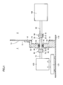
- Fig. 1 is a partial cross sectional schematic view illustrating the configuration of a power transmission device according to a first embodiment of the present invention.
- a space 1 serving as a first space forms the external space of a radio wave-shielding structural body.
- a space 2 serving as a second space forms the internal space of the radio wave-shielding structural body.
- Spaces 1 and 2 are formed as the spaces separated and partitioned by an electromagnetic wave-shielding wall 10 and adjacent to each other.
- Electromagnetic wave-shielding wall 10 shields an electromagnetic wave propagating from one to the other of space 1 and space 2.
- Electromagnetic wave-shielding wall 10 for blocking the propagation of an electromagnetic wave between space 1 and space 2 is provided such that the propagation of an electromagnetic wave generated by a driver 120 installed in space 1 to space 2 is blocked.
- Driver 120 is placed on a bed 122 provided on the floor part 110. This grounds driver 120.
- a through hole 12 Formed in electromagnetic wave-shielding wall 10 is a through hole 12.
- Through hole 12 is formed by drilling a hole penetrating through electromagnetic wave-shielding wall 10 in the thickness direction in a portion of electromagnetic wave-shielding wall 10.
- a rotating shaft 20 is disposed in a manner to extend through the inside of through hole 12 from space 1 to space 2.
- Rotating shaft 20 penetrates through electromagnetic wave-shielding wall 10 to transmit rotational drive force between driver 120 arranged within space 1 and a driven body 106 arranged within space 2.
- Rotating shaft 20 is provided in a manner to be able to transmit rotating drive force between space 1 and space 2 which are partitioned by electromagnetic wave-shielding wall 10.
- Fig. 2 is a conceptual view illustrating details and the grounding status of rotating shaft 20.
- rotating shaft 20 is rotatably supported by a bearing 80.
- Bearing 80 includes two rolling bearings 81, 86.
- Rolling bearing 81 has inner and outer races 82 and 83 formed into a circular ring shape and a ball 84 serving as a rolling element which is held by and between inner race 82 and outer race 83.
- a plurality of balls 84 are in contact with the inner circumferential surface of outer race 83 and the outer circumferential surface of inner race 82 and arranged with a predetermined pitch in the circumferential direction by a cage which is not shown in the drawings, thereby being rollably held on a circular ring-like track.
- Inner race 82 and outer race 83 which are arranged opposite to each other, are allowed to rotate relative to each other.
- Inner race 82 and outer race 83 are arranged in an opposing and relatively rotatable manner.
- Rolling bearing 86 has inner and outer races 87 and 88 formed into a circular ring shape and a ball 89 serving as a rolling element which is held by and between inner race 87 and outer race 88.
- a plurality of balls 89 are in contact with the inner circumferential surface of outer race 88 and the outer circumferential surface of inner race 87 and arranged with a predetermined pitch in the circumferential direction by a cage which is not shown in the drawings, thereby being rollably held on a circular ring-like track.
- Inner race 87 and outer race 88 which are arranged opposite to each other, are allowed to rotate relative to each other.
- Inner race 87 and outer race 88 are arranged in an opposing and relatively rotatable manner.
- Bearing stand 16 is fixed to electromagnetic wave-shielding wall 10 and bearing stand 16 and electromagnetic wave-shielding wall 10 are electrically connected.
- Bearing stand 16 has a close-contact surface 18 which is in close contact with electromagnetic wave-shielding wall 10. Close-contact surface 18 is formed annularly. Close-contact surface 18 of bearing stand 16 is, with no clearance, in close contact with a surface 11 which is one surface of electromagnetic wave-shielding wall 10.
- Bearing stand 16 is provided as a construction in a single-piece with electromagnetic wave-shielding wall 10.
- Outer races 83, 88 surrounding the circumference of rotating shaft 20 in the circumferential direction with no clearance are supported from their outer circumferential sides by bearing stand 16 which has a cylindrical sleeve part 16a (see Fig. 2 ) covering the circumference of rotating shaft 20 with no clearance.
- Rotating shaft 20 includes a first shaft member 30, a second shaft member 40, and a shaft joint part 50 lying between first shaft member 30 and second shaft member 40.
- Rotating shaft 20 also includes a third shaft member 70 and another shaft joint part 60 lying between first shaft member 30 and third shaft member 70.
- Bearing 80 pivotally supports first shaft member 30, thereby rotatably supporting rotating shaft 20.
- First shaft member 30 is pivotally supported by bearing 80.
- First shaft member 30 is arranged to span from space 1 to space 2 with an end 31 being arranged on the space 2 side and the other end 32 opposite to end 31 being arranged on space 1 side.
- first shaft member 30 End 31 and the other end 32 of first shaft member 30 are formed into a flange shape which is enlarged in diameter.
- Shaft joint part 50 is provided at end 31 of first shaft member 30.
- the other shaft joint part 60 is provided at the other end 32 of first shaft member 30.
- Second shaft member 40 is provided to be rotatable together with first shaft member 30 with shaft joint part 50 interposed therebetween.
- Third shaft member 70 is provided to be rotatable together with first shaft member 30, with the other shaft joint part 60 interposed therebetween.
- First shaft member 30, second shaft member 40 and third shaft member 70 are made to be coaxially rotatable.
- Shaft joint part 50 has end 31 of first shaft member 30, end 41 of second shaft member 40 and a coupling 51.
- Coupling 51 is an example of an insulating part formed of an insulating material.
- first shaft member 30 and second shaft member 40 are formed of a conductive material, insulating coupling 51 provided between ends 31, 41 provides a configuration in which the propagation of an electromagnetic wave between first shaft member 30 and second shaft member 40 can be blocked.
- Fig. 3 is a cross sectional view illustrating an example of details of the structure of shaft joint part 50.
- Fig. 4 is a front view of an example of coupling 51.
- Fig. 4 shows coupling 51 shown in Fig. 3 when viewed from the left side in Fig. 3 .
- a dent part 53 is formed at four locations. Dent part 53 is formed such that surface 52 of coupling 51 is concaved and has a cylindrical internal surface.
- a bolt hole 54 penetrating through coupling 51 in the thickness direction is so formed as to reach from the bottom surface of each dent part 53 to the back side 55 of coupling 51.
- a through hole 42 is formed at four locations. Through hole 42 is formed to be equal to bolt hole 54 in diameter and phase. A bolt 43 is inserted into the through hole 42 and bolt hole 54 in a manner to penetrate therethrough, and fixation of bolt 43 with a nut 44 fixes coupling 51 and end 41 of second shaft member 40 together.
- a dent part 56 is formed at four locations.
- a bolt hole 57 penetrating through coupling 51 in the thickness direction is so formed to reach from the bottom surface of each dent part 56 to the front side 52 of coupling 51.
- a through hole 35 is formed at four locations to be equal to bolt hole 57 in diameter and phase.
- a bolt 33 is inserted into through the through holes 35 and bolt hole 57 in a manner to penetrate therethrough, and fixation of bolt 33 with a nut 34 fixes coupling 51 and end 31 of first shaft member 30 together.
- first shaft member 30 and second shaft member 40 are not in direct contact with each other, insulating coupling 51 lies between first shaft member 30 and second shaft member 40, and the electrical resistance between first shaft member 30 and second shaft member 40 is large. This makes an electromagnetic wave unlikely to be propagated between first shaft member 30 and second shaft member 40. Since first shaft member 30 and second shaft member 40 are coupled to each other, with shaft joint part 50 interposed therebetween and having coupling 51 serving as an insulating part, an electromagnetic wave propagating from the space 1 side to the space 2 side by way of rotating shaft 20 is made unlikely to be transmitted from first shaft member 30 to shaft joint part 50.
- bearing 80 pivotally supporting first shaft member 30 includes an inner race component part which is formed to fit to an outer circumferential surface 39 of first shaft member 30 and to be rotatable.
- This inner race component part includes inner races 82, 87.
- Bearing 80 also includes an outer race component part which is arranged opposite to the inner race component part with balls 84, 89 interposed therebetween.
- This outer race component part has outer races 83, 88 and bearing stand 16 (sleeve part 16a) for fixing outer races 83, 88.
- the inner circumferential surface of outer races 83, 88 forms a track surface of bearing 80 (rolling bearings 81, 86), together with the outer circumferential surface of inner races 82, 87.
- the inner race component part, the rolling element, and the outer race component part are each formed of a conductive material such as a metal material, which is represented by bearing steel.
- An electromagnetic wave propagates to a path having a lower electrical resistance value. This makes an electromagnetic wave more likely to be transmitted from first shaft member 30 to the outer race component part by way of the inner race component part and the rolling element.
- the outer race component part is in close contact with electromagnetic wave-shielding wall 10.
- Bearing stand 16 included in the outer race component part is electrically connected to an earth part 123 which is a conductive body.
- Bearing 80 rotatably supporting first shaft member 30 is grounded (earthed) via earth part 123.
- outer race 83 of rolling bearing 81 and outer race 88 of rolling bearing 86 are supported by bearing stand 16 (sleeve part 16a) in a fixed manner.
- the outer peripheral surface of sleeve part 16a is formed into a cylindrical shape.
- this outer peripheral surface having a cylindrical shape can be brought into close contact with electromagnetic wave-shielding wall 10 to form annular close-contact surface 18.
- annular close-contact surface 18 may be formed by bringing a circular ring-shaped surface formed on an end of sleeve part 16a into close contact with electromagnetic wave-shielding wall 10.
- the other shaft joint part 60 lying between first shaft member 30 and third shaft member 70 has the other end 32 of first shaft member 30, end 72 of third shaft member 70 and a coupling 62.
- Coupling 62 is an example of another insulating part formed of an insulating material.
- first shaft member 30 and third shaft member 70 are formed of a conductive material, insulating coupling 62 provided between the other end 32 of first shaft member 30 and end 72 of the third shaft member provides a configuration in which the propagation of an electromagnetic wave between first shaft member 30 and third shaft member 70 can be suppressed.
- the other shaft joint part 60 can be formed to have the same configuration as shaft joint part 50 described with reference to Figs. 3 and 4 . By doing so, first shaft member 30 and third shaft member 70 will not be in direct contact with each other. Insulating coupling 62 interposed between first shaft member 30 and third shaft member 70 increases the electrical resistance between first shaft member 30 and third shaft member 70. This makes an electromagnetic wave unlikely to be propagated between first shaft member 30 and third shaft member 70.
- first shaft member 30 and third shaft member 70 are coupled to each other, with shaft joint part 60 interposed therebetween and having coupling 62 serving as another insulating part, an electromagnetic wave propagating from the space 1 side to the space 2 side by way of rotating shaft 20 is made unlikely to be transmitted from third shaft member 70 to shaft joint part 60.
- An electromagnetic wave to be transmitted by way of rotating shaft 20 to first shaft member 30 is attenuated when passing through shaft joint part 60. Accordingly, by providing the other shaft joint part 60, an electromagnetic wave propagated to first shaft member 30 by way of rotating shaft 20 can reduced, and therefore, leakage of an electromagnetic wave from space 1 to space 2 by way of first shaft member 30 can be further suppressed.
- earthing brushes 91, 92 as an example of a grounding member are in contact with outer circumferential surface 39 of first shaft member 30.
- Earthing brushes 91, 92 have brush parts 93, 95 formed of a conductive material and in contact with outer circumferential surface 39 of first shaft member 30, as shown in Fig. 2 .
- Earthing brushes 91, 92 also have wires 94, 96 electrically connecting brush parts 93, 95 and earth part 123.
- Earthing brushes 91, 92 electrically connect outer circumferential surface 39 of first shaft member 30 and electromagnetic wave-shielding wall 10.
- Earthing brushes 91, 92 ground first shaft member 30.
- first shaft member 30 By providing earthing brushes 91, 92, paths electrically connecting first shaft member 30 and electromagnetic wave-shielding wall 10 are increased in number. If an electromagnetic wave propagated to first shaft member 30 propagates to any of bearing 80 and earthing brushes 91, 92, then an electromagnetic wave propagating to second shaft member 40 can be reduced. Accordingly, leakage of an electromagnetic wave from space 1 to space 2 by way of rotating shaft 20 can be effectively suppressed, achieving a further reduction of leakage of an electromagnetic wave to space 2.
- Earthing brushes 91, 92 are arranged to be in contact with outer circumferential surface 39 which is the outer surface of first shaft member 30.
- Fig. 5 is a partial cross sectional schematic view illustrating the configuration of a power transmission device according to a second embodiment.
- the power transmission device of the second embodiment varies from that of the first embodiment in that the device further includes another bearing 180 pivotally supporting third shaft member 70 and that a bearing stand 116 included in an outer race component part of bearings 80, 180 is arranged to cover entire outer circumferential surfaces 39, 79 of rotating shaft 20 from bearing 80 to the other bearing 180.
- the other bearing 180 includes two rolling bearings 181, 186, as in bearing 80.
- Rolling bearings 181, 186 have inner races 182, 187 and outer races 183, 188 formed into a circular ring shape and balls 184, 189 serving as rolling elements which are held by and between inner races 182, 187 and outer races 183, 188, respectively.
- Inner races 182, 187 are included in an inner race component part, and outer races 183, 188 and bearing stand 116 supporting outer races 183, 188 in a fixed manner are included in an outer race component part.
- Inner races 182, 187 included in another inner race component part are arranged opposite to the outer race component part including bearing stand 116, and formed to fit to third shaft member 70 and to be rotatable.
- a plurality of balls 184, 189 are in contact with the inner circumferential surface of outer races 183, 188 and the outer circumferential surface of inner races 182, 187 and arranged with a predetermined pitch in the circumferential direction by a cage which is not shown in the drawings, thereby being rollably held on circular ring-like tracks.
- Inner races 182, 187 and outer races 183, 188, which are arranged opposite to each other, are allowed to rotate relative to each other.
- Inner races 182, 187 and outer races 183, 188 are arranged in an opposing and relatively rotatable manner.
- Bearing stand 116 is fixed to electromagnetic wave-shielding wall 10, and bearing stand 116 and electromagnetic wave-shielding wall 10 are electrically connected. Bearing stand 116 is in close contact with electromagnetic wave-shielding wall 10 with no clearance. Bearing stand 116 is provided as a single-piece construction with electromagnetic wave-shielding wall 10. Outer races 183, 188 encircling the circumference of rotating shaft 20 in the circumferential direction with no clearance are supported, from their outer circumferential sides, by bearing stand 116 which is formed into a tubular shape covering the circumference of rotating shaft 20 with no clearance.
- rotating shaft 20 of the second embodiment having a configuration as above, since first shaft member 30 and third shaft member 70 are coupled to each other, with the other shaft joint part 60 interposed therebetween and having coupling 62 serving as another insulating part, an electromagnetic wave propagating from the space 1 side to the space 2 side by way of rotating shaft 20 is made unlikely to be transmitted from third shaft member 70 to the other shaft joint part 60.
- the inner race component part, the rolling elements and the outer race component part of the other bearing 180 are each formed of a conductive material such as a metal material, which is represented by bearing steel. This makes an electromagnetic wave more likely to be transmitted from third shaft member 70 to the outer race component part by way of the inner race component part and rolling elements of the other bearing 180.
- the other bearing 180 rotatably supporting third shaft member 70 is grounded (earthed) via bearing stand 116. If an electromagnetic wave is propagated from the space 1 side to third shaft member 70, since the transmission of an electromagnetic wave from third shaft member 70 to the other shaft joint part 60 is suppressed, much of the propagated electromagnetic wave to third shaft member 70 will then propagate to the grounded another bearing 180. Consequently, the propagation of an electromagnetic wave from third shaft member 70 to first shaft member 30 by way of the other shaft joint part 60 can be suppressed, and therefore, leakage of an electromagnetic wave from space 1 to space 2 by way of rotating shaft 20 can be further suppressed, achieving a further reduction of leakage of an electromagnetic wave to space 2.
- a shaft joint part 160 is provided on the other end 71 of third shaft member 70.
- Shaft joint part 160 has the other end 71 of third shaft member 70, a coupling 161 formed of an insulating material, and an end 171 of a fourth shaft member 170 coupled to third shaft member 70 with coupling 161 interposed therebetween.
- insulating coupling 161 is provided between end 171 of fourth shaft member 170 and the other end 71 of the third shaft member, the propagation of an electromagnetic wave between fourth shaft member 170 and third shaft member 70 can be blocked.
- bearing stand 116 of the second embodiment covers a wider range of the outer circumferential surface of rotating shaft 20 as compared with bearing stand 16 of the first embodiment.
- Earthing brush 91 is arranged to electrically connect outer circumferential surface 79 of third shaft member 70 and bearing stand 116.
- Earthing brush 92 are arranged to electrically connect outer circumferential surface 39 of first shaft member 30 and electromagnetic wave-shielding wall 10.
- Earthing brushes 91, 92 for effectively eliminating an electromagnetic wave of a high frequency propagating through the surface of rotating shaft 20 may be installed at any position. There is, however, a need to replace earthing brushes 91, 92 when earthing brushes 91, 92 are worn due to their sliding movement against rotating shaft 20. In order to improve ease of maintenance, it is desirable to arrange earthing brushes 91, 92 at positions which allow for easy changing of earthing brushes 91, 92. Specifically, it is desirable, as shown in Fig. 5 , for example, to arrange earthing brushes 91, 92 to be in contact with rotating shaft 20 at a position where the outer circumferential surface thereof is not covered with bearing stand 116.
- bearings 80, 180 pivotally supporting rotating shaft 20 include rolling bearings 81, 86, 181 and 186.
- a roller may be used as a rolling element in lieu of a ball.
- a sliding bearing may be used to pivotally support rotating shaft 20.
- shaft joint parts 50, 60, 160 are not limited to the configurations shown in Figs. 3 and 4 .
- Shaft joint parts 50, 60, 160 can, rather, be applied with any configuration in so far as shaft joint parts 50, 60, 160 have insulating parts formed of an insulating material and can suppress the propagation of an electromagnetic wave between two shaft members coupled by shaft joint parts 50, 60, 160.
- the present invention is advantageously applicable in particular to a power transmission device for transmitting rotating drive force by means of a rotating shaft penetrating through a wall part of a radio wave-shielded room, from the outside to the inside (or from the inside to the outside) of the radio wave-shielding room.
Landscapes
- Engineering & Computer Science (AREA)
- General Engineering & Computer Science (AREA)
- Mechanical Engineering (AREA)
- Architecture (AREA)
- Microelectronics & Electronic Packaging (AREA)
- Civil Engineering (AREA)
- Structural Engineering (AREA)
- Shielding Devices Or Components To Electric Or Magnetic Fields (AREA)
- Rolling Contact Bearings (AREA)
- Shafts, Cranks, Connecting Bars, And Related Bearings (AREA)
Abstract
Description
- The present invention relates to a power transmission device, and particularly to a power transmission device which penetrates through a shield wall for blocking the propagation of an electromagnetic wave, to transmit rotational driving force.
- Conventionally, it has been a common practice to form an electromagnetic wave-shielded room for the purpose of shielding an externally intruding unnecessary electromagnetic wave and preventing leakage of an internally generated electromagnetic wave to the outside. An electromagnetic wave-shielded room is formed with an intended section being surrounded with a plate member of a conductive body and the plate member being grounded. When power is to be transmitted from one to the other of the inside and the outside of an electromagnetic wave-shielded room, a through hole is formed in a plate member for blocking the propagation of an electromagnetic wave, and a power transmission shaft penetrating through the through hole is provided, thereby allowing power to be transmitted through the plate member forming the electromagnetic wave-shielded room.
- When an electromagnetic wave-shielded room is provided with a power transmission shaft in the above manner, in the event of leakage of a radio wave by way of the through hole or leakage of a radio wave transmitted through the shaft, the shielding performance against an electromagnetic wave would be degraded. In particular, the higher frequency an electromagnetic wave has, the more likely the electromagnetic wave is to be transmitted by way of the surface of the shaft due to the skin effect. In order to achieve improved shielding performance against an electromagnetic wave of a high frequency, it is necessary to block an electromagnetic wave leaking through the shaft surface. To that end, a technology has been proposed in which a through hole formed in a plate member of a conductive body is penetrated thorough by a sleeve made of metal so that leakage of an electromagnetic wave by way of the through hole is suppressed, and in which a direct-coupling shaft of an insulating material is inserted into the sleeve so that leakage of an electromagnetic wave by way of the shaft is also suppressed (for example, see Japanese Patent Laying-Open No.
8-326340 - Patent Document 1: Japanese Patent Laying-Open No.
8-326340 - When using the technology as described in Japanese Patent Laying-Open No.
8-326340 - The present invention has been made in view of the problems above, and a main object of the invention is to provide a power transmission device which penetrates through a shield wall for blocking the propagation of an electromagnetic wave, to transmit rotational driving force and in which leakage of an electromagnetic wave can be effectively suppressed without inviting enlargement of the size and degradation of the torque transmission capability of the device.
- The power transmission device according to the present invention includes an electromagnetic wave-shielding wall, a rotating shaft and a bearing. The electromagnetic wave-shielding wall partitions a first space and a second space adjacent to the first space and blocks propagation of an electromagnetic wave between the first space and the second space. The rotating shaft is rotatably provided and penetrating through the electromagnetic wave-shielding wall to transmit rotational drive force between the first space and the second space. The bearing rotatably supports the rotating shaft. The rotating shaft includes a first shaft member pivotally supported by the bearing, a shaft joint part provided on an end of the first shaft member on the second space side, and a second shaft member provided to be rotatable together with the first shaft member with the shaft joint part interposed between the first and second shaft members. The first shaft member and the second shaft member are formed of a conductive material. The shaft joint part has an insulating part which is formed of an insulating material and blocks propagation of an electromagnetic wave between the first shaft member and the second shaft member. The bearing includes an inner race component part and an outer race component part which are arranged opposite to each other. The inner race component part is formed to fit to the first shaft member and to be rotatable. The outer race component part is formed of a conductive material and fixed to the electromagnetic wave-shielding wall. The outer race component part has an annular close-contact surface in close contact with the electromagnetic wave-shielding wall.
- Preferably, in the above-described power transmission device, a grounding member formed of a conductive material is further included. The grounding member is arranged to be in contact with an outer circumferential surface of the first shaft member and electrically connected to the electromagnetic wave-shielding wall.
- Preferably, in the above-described power transmission device, the rotating shaft further includes another shaft joint part provided on the other end opposite to the end of the first shaft member and a third shaft member provided to be rotatable together with the first shaft member with the other shaft joint part interposed between the first and the thrid shaft members. The third shaft member is formed of a conductive material. The other shaft joint part has another insulating part. The other insulating part is formed of an insulating material and blocks propagation of an electromagnetic wave between the first shaft member and the third shaft member.
- Preferably, in the above-described power transmission device, another bearing pivotally supporting the third shaft member is further included. The other bearing includes another inner race component part. The other inner race component part is arranged opposite to the outer race component part and formed to fit to the third shaft member and to be rotatable. The outer race component part is arranged to cover entire outer circumferential surface of the rotating shaft from the bearing to the other bearing.
- According to the power transmission device of the present invention, an outer race component part of a bearing pivotally supporting a first shaft member of a rotating shaft is fixed to an electromagnetic wave-shielding wall, and the bearing is grounded via the electromagnetic wave-shielding wall. Further, a shaft joint part having an insulating part is arranged on the second space side relative to the bearing. This makes an electromagnetic wave propagating from the first space side to the second space side by way of the rotating shaft relatively more likely to be transmitted from the first shaft member to the bearing than from the first shaft member to the shaft joint part. That is, most of an electromagnetic wave propagated from the first space side to the first shaft member will propagate to the grounded bearing. Accordingly, the propagation of an electromagnetic wave from the first shaft member to the second shaft member by way of the shaft joint part can be suppressed, and therefore, leakage of an electromagnetic wave from the first space to the second space by way of the rotating shaft can be suppressed.
-
-
Fig. 1 is a partial cross sectional schematic view illustrating the configuration of a power transmission device according to a first embodiment of the present invention. -
Fig. 2 is a conceptual view illustrating details and the grounding status of a rotating shaft. -
Fig. 3 is a cross sectional view illustrating an example of details of the structure of a shaft joint part. -
Fig. 4 is a front view of an example of a coupling. -
Fig. 5 is a partial cross sectional schematic view illustrating the configuration of a power transmission device according to a second embodiment. - 1,2 space, 10 electromagnetic wave-shielding wall, 11 surface, 12 through hole, 16, 116 bearing stand, 16a sleeve part, 18 close-contact surface, 20 rotating shaft, 30 first shaft member, 31, 41, 72, 171 end, 32, 71 the other end, 33, 43 bolt, 34, 44 nut, 35, 42 through hole, 39, 79 outer circumferential surface, 40 second shaft member, 50, 60, 160 shaft joint part, 51, 62, 161 coupling, 70 second shaft member, 80, 180 bearing, 91, 92 earthing brush, 93, 95 brush part, 94, 96 wire, 106 driven body, 110 floor part, 122 bed, 120 driver, 123 earth part, 170 fourth shaft member.
- Embodiments of the present invention will be described hereinafter with reference to the drawings. In the drawings below, the same or corresponding elements have the same reference numerals allotted, and description thereof will not be repeated.
- In the embodiments described hereinafter, each component is not necessarily indispensable in the present invention unless otherwise specified. In addition, in the embodiments below, reference to the number, an amount or the like is merely by way of example unless otherwise specified, and the scope of the present invention is not necessarily limited to that number, that amount or the like.
-
Fig. 1 is a partial cross sectional schematic view illustrating the configuration of a power transmission device according to a first embodiment of the present invention. Aspace 1 serving as a first space forms the external space of a radio wave-shielding structural body. Aspace 2 serving as a second space forms the internal space of the radio wave-shielding structural body.Spaces shielding wall 10 and adjacent to each other. Electromagnetic wave-shielding wall 10 shields an electromagnetic wave propagating from one to the other ofspace 1 andspace 2. Electromagnetic wave-shielding wall 10 for blocking the propagation of an electromagnetic wave betweenspace 1 andspace 2 is provided such that the propagation of an electromagnetic wave generated by adriver 120 installed inspace 1 tospace 2 is blocked.Driver 120 is placed on abed 122 provided on thefloor part 110. Thisgrounds driver 120. - Formed in electromagnetic wave-shielding
wall 10 is a throughhole 12. Throughhole 12 is formed by drilling a hole penetrating through electromagnetic wave-shieldingwall 10 in the thickness direction in a portion of electromagnetic wave-shieldingwall 10. A rotatingshaft 20 is disposed in a manner to extend through the inside of throughhole 12 fromspace 1 tospace 2. Rotatingshaft 20 penetrates through electromagnetic wave-shieldingwall 10 to transmit rotational drive force betweendriver 120 arranged withinspace 1 and a drivenbody 106 arranged withinspace 2. Rotatingshaft 20 is provided in a manner to be able to transmit rotating drive force betweenspace 1 andspace 2 which are partitioned by electromagnetic wave-shieldingwall 10. -
Fig. 2 is a conceptual view illustrating details and the grounding status ofrotating shaft 20. As shown inFigs. 1 and2 , rotatingshaft 20 is rotatably supported by abearing 80.Bearing 80 includes two rollingbearings - Rolling bearing 81 has inner and
outer races ball 84 serving as a rolling element which is held by and betweeninner race 82 andouter race 83. A plurality ofballs 84 are in contact with the inner circumferential surface ofouter race 83 and the outer circumferential surface ofinner race 82 and arranged with a predetermined pitch in the circumferential direction by a cage which is not shown in the drawings, thereby being rollably held on a circular ring-like track.Inner race 82 andouter race 83, which are arranged opposite to each other, are allowed to rotate relative to each other.Inner race 82 andouter race 83 are arranged in an opposing and relatively rotatable manner. - Rolling bearing 86 has inner and
outer races ball 89 serving as a rolling element which is held by and betweeninner race 87 andouter race 88. A plurality ofballs 89 are in contact with the inner circumferential surface ofouter race 88 and the outer circumferential surface ofinner race 87 and arranged with a predetermined pitch in the circumferential direction by a cage which is not shown in the drawings, thereby being rollably held on a circular ring-like track.Inner race 87 andouter race 88, which are arranged opposite to each other, are allowed to rotate relative to each other.Inner race 87 andouter race 88 are arranged in an opposing and relatively rotatable manner. -
Outer races stand 16 in a fixed manner. Bearing stand 16 is fixed to electromagnetic wave-shieldingwall 10 and bearing stand 16 and electromagnetic wave-shieldingwall 10 are electrically connected. Bearing stand 16 has a close-contact surface 18 which is in close contact with electromagnetic wave-shieldingwall 10. Close-contact surface 18 is formed annularly. Close-contact surface 18 of bearing stand 16 is, with no clearance, in close contact with asurface 11 which is one surface of electromagnetic wave-shieldingwall 10. Bearing stand 16 is provided as a construction in a single-piece with electromagnetic wave-shieldingwall 10.Outer races shaft 20 in the circumferential direction with no clearance are supported from their outer circumferential sides by bearingstand 16 which has acylindrical sleeve part 16a (seeFig. 2 ) covering the circumference of rotatingshaft 20 with no clearance. - Rotating
shaft 20 includes afirst shaft member 30, asecond shaft member 40, and a shaftjoint part 50 lying betweenfirst shaft member 30 andsecond shaft member 40. Rotatingshaft 20 also includes athird shaft member 70 and another shaftjoint part 60 lying betweenfirst shaft member 30 andthird shaft member 70.Bearing 80 pivotally supportsfirst shaft member 30, thereby rotatably supportingrotating shaft 20.First shaft member 30 is pivotally supported by bearing 80.First shaft member 30 is arranged to span fromspace 1 tospace 2 with anend 31 being arranged on thespace 2 side and theother end 32 opposite to end 31 being arranged onspace 1 side. -
End 31 and theother end 32 offirst shaft member 30 are formed into a flange shape which is enlarged in diameter. Shaftjoint part 50 is provided atend 31 offirst shaft member 30. The other shaftjoint part 60 is provided at theother end 32 offirst shaft member 30.Second shaft member 40 is provided to be rotatable together withfirst shaft member 30 with shaftjoint part 50 interposed therebetween.Third shaft member 70 is provided to be rotatable together withfirst shaft member 30, with the other shaftjoint part 60 interposed therebetween.First shaft member 30,second shaft member 40 andthird shaft member 70 are made to be coaxially rotatable. - Shaft
joint part 50 hasend 31 offirst shaft member 30, end 41 ofsecond shaft member 40 and acoupling 51.Coupling 51 is an example of an insulating part formed of an insulating material. Althoughfirst shaft member 30 andsecond shaft member 40 are formed of a conductive material, insulatingcoupling 51 provided between ends 31, 41 provides a configuration in which the propagation of an electromagnetic wave betweenfirst shaft member 30 andsecond shaft member 40 can be blocked. -
Fig. 3 is a cross sectional view illustrating an example of details of the structure of shaftjoint part 50.Fig. 4 is a front view of an example ofcoupling 51.Fig. 4 showscoupling 51 shown inFig. 3 when viewed from the left side inFig. 3 . As shown inFigs. 3 and4 , on asurface 52 ofcoupling 51, adent part 53 is formed at four locations.Dent part 53 is formed such thatsurface 52 ofcoupling 51 is concaved and has a cylindrical internal surface. Abolt hole 54 penetrating throughcoupling 51 in the thickness direction is so formed as to reach from the bottom surface of eachdent part 53 to theback side 55 ofcoupling 51. - In flange-
like end 41 ofsecond shaft member 40, a throughhole 42 is formed at four locations. Throughhole 42 is formed to be equal to bolthole 54 in diameter and phase. Abolt 43 is inserted into the throughhole 42 andbolt hole 54 in a manner to penetrate therethrough, and fixation ofbolt 43 with anut 44 fixes coupling 51 and end 41 ofsecond shaft member 40 together. - Likewise, on
back side 55 ofcoupling 51, adent part 56 is formed at four locations. Abolt hole 57 penetrating throughcoupling 51 in the thickness direction is so formed to reach from the bottom surface of eachdent part 56 to thefront side 52 ofcoupling 51. In flange-like end 31 offirst shaft member 30, a throughhole 35 is formed at four locations to be equal to bolthole 57 in diameter and phase. Abolt 33 is inserted into through the throughholes 35 andbolt hole 57 in a manner to penetrate therethrough, and fixation ofbolt 33 with anut 34 fixes coupling 51 and end 31 offirst shaft member 30 together. - By screw
engagement using bolts first shaft member 30 and end 41 ofsecond shaft member 40 are coupled together, withcoupling 51 interposed therebetween. At this time, as shown inFig. 3 ,bolt 33 andnut 34 couplingfirst shaft member 30 andcoupling 51 are not in contact withsecond shaft member 40, and a clearance is formed betweenbolt 33 andnut 34 and end 41 ofsecond shaft member 40. Further,bolt 43 andnut 44 couplingsecond shaft member 40 andcoupling 51 are not in contact withfirst shaft member 30, and a clearance is formed betweenbolt 43 andnut 44 and end 31 offirst shaft member 30. - As such,
first shaft member 30 andsecond shaft member 40 are not in direct contact with each other, insulatingcoupling 51 lies betweenfirst shaft member 30 andsecond shaft member 40, and the electrical resistance betweenfirst shaft member 30 andsecond shaft member 40 is large. This makes an electromagnetic wave unlikely to be propagated betweenfirst shaft member 30 andsecond shaft member 40. Sincefirst shaft member 30 andsecond shaft member 40 are coupled to each other, with shaftjoint part 50 interposed therebetween and havingcoupling 51 serving as an insulating part, an electromagnetic wave propagating from thespace 1 side to thespace 2 side by way of rotatingshaft 20 is made unlikely to be transmitted fromfirst shaft member 30 to shaftjoint part 50. - On the other hand, bearing 80 pivotally supporting
first shaft member 30 includes an inner race component part which is formed to fit to an outercircumferential surface 39 offirst shaft member 30 and to be rotatable. This inner race component part includesinner races Bearing 80 also includes an outer race component part which is arranged opposite to the inner race component part withballs outer races sleeve part 16a) for fixingouter races outer races bearings 81, 86), together with the outer circumferential surface ofinner races - The inner race component part, the rolling element, and the outer race component part are each formed of a conductive material such as a metal material, which is represented by bearing steel. An electromagnetic wave propagates to a path having a lower electrical resistance value. This makes an electromagnetic wave more likely to be transmitted from
first shaft member 30 to the outer race component part by way of the inner race component part and the rolling element. As described above, the outer race component part is in close contact with electromagnetic wave-shieldingwall 10. Bearing stand 16 included in the outer race component part is electrically connected to anearth part 123 which is a conductive body.Bearing 80 rotatably supportingfirst shaft member 30 is grounded (earthed) viaearth part 123. - If an electromagnetic wave is propagated from the
space 1 side tofirst shaft member 30, since the transmission of an electromagnetic wave fromfirst shaft member 30 to shaftjoint part 50 is suppressed, much of the propagated electromagnetic wave tofirst shaft member 30 will then propagate to groundedbearing 80. Consequently, the propagation of an electromagnetic wave fromfirst shaft member 30 tosecond shaft member 40 by way of shaftjoint part 50 can be suppressed, and therefore, leakage of an electromagnetic wave fromspace 1 tospace 2 by way of rotatingshaft 20 can be suppressed, achieving reduction of leakage of an electromagnetic wave tospace 2. - As already described,
outer race 83 of rollingbearing 81 andouter race 88 of rollingbearing 86 are supported by bearing stand 16 (sleeve part 16a) in a fixed manner. The outer peripheral surface ofsleeve part 16a is formed into a cylindrical shape. For instance, this outer peripheral surface having a cylindrical shape can be brought into close contact with electromagnetic wave-shieldingwall 10 to form annular close-contact surface 18. Further, annular close-contact surface 18 may be formed by bringing a circular ring-shaped surface formed on an end ofsleeve part 16a into close contact with electromagnetic wave-shieldingwall 10. - In order to prevent formation of any clearance between
sleeve part 16a and electromagnetic wave-shieldingwall 10, by bringingsleeve part 16a into close contact with electromagnetic wave-shieldingwall 10 directly or with another member interposed therebetween, the outer circumferential surface of rotatingshaft 20 on the side in the proximity of shaftjoint part 50 relative to bearing 80 (i.e., on thespace 2 side) is circumferentially surrounded with no clearance. Thus, even when the electromagnetic wave density withinspace 1 is higher than that withinspace 2 due to generation of an electromagnetic wave fromdriver 120, rotatingshaft 20 located on thespace 2 side relative to bearing 80 will not be in direct contact with the high electromagnetic wave density. Thus, upon release of, by way of bearing 80, an electromagnetic wave propagating throughrotating shaft 20, the propagation of an electromagnetic wave fromspace 1 to rotatingshaft 20 can be prevented. Therefore, leakage of an electromagnetic wave tospace 2 by way of rotatingshaft 20 can be more effectively suppressed. - As shown in
Fig. 2 , the other shaftjoint part 60 lying betweenfirst shaft member 30 andthird shaft member 70 has theother end 32 offirst shaft member 30, end 72 ofthird shaft member 70 and acoupling 62.Coupling 62 is an example of another insulating part formed of an insulating material. Althoughfirst shaft member 30 andthird shaft member 70 are formed of a conductive material, insulatingcoupling 62 provided between theother end 32 offirst shaft member 30 and end 72 of the third shaft member provides a configuration in which the propagation of an electromagnetic wave betweenfirst shaft member 30 andthird shaft member 70 can be suppressed. - The other shaft
joint part 60 can be formed to have the same configuration as shaftjoint part 50 described with reference toFigs. 3 and4 . By doing so,first shaft member 30 andthird shaft member 70 will not be in direct contact with each other. Insulatingcoupling 62 interposed betweenfirst shaft member 30 andthird shaft member 70 increases the electrical resistance betweenfirst shaft member 30 andthird shaft member 70. This makes an electromagnetic wave unlikely to be propagated betweenfirst shaft member 30 andthird shaft member 70. - That is, since
first shaft member 30 andthird shaft member 70 are coupled to each other, with shaftjoint part 60 interposed therebetween and havingcoupling 62 serving as another insulating part, an electromagnetic wave propagating from thespace 1 side to thespace 2 side by way of rotatingshaft 20 is made unlikely to be transmitted fromthird shaft member 70 to shaftjoint part 60. An electromagnetic wave to be transmitted by way of rotatingshaft 20 tofirst shaft member 30 is attenuated when passing through shaftjoint part 60. Accordingly, by providing the other shaftjoint part 60, an electromagnetic wave propagated tofirst shaft member 30 by way of rotatingshaft 20 can reduced, and therefore, leakage of an electromagnetic wave fromspace 1 tospace 2 by way offirst shaft member 30 can be further suppressed. - Further, as shown in
Figs. 1 and2 , earthing brushes 91, 92 as an example of a grounding member are in contact with outercircumferential surface 39 offirst shaft member 30. Earthing brushes 91, 92 havebrush parts circumferential surface 39 offirst shaft member 30, as shown inFig. 2 . Earthing brushes 91, 92 also havewires brush parts earth part 123. Earthing brushes 91, 92 electrically connect outercircumferential surface 39 offirst shaft member 30 and electromagnetic wave-shieldingwall 10. Earthing brushes 91, 92 groundfirst shaft member 30. - By providing earthing brushes 91, 92, paths electrically connecting
first shaft member 30 and electromagnetic wave-shieldingwall 10 are increased in number. If an electromagnetic wave propagated tofirst shaft member 30 propagates to any of bearing 80 and earthing brushes 91, 92, then an electromagnetic wave propagating tosecond shaft member 40 can be reduced. Accordingly, leakage of an electromagnetic wave fromspace 1 tospace 2 by way of rotatingshaft 20 can be effectively suppressed, achieving a further reduction of leakage of an electromagnetic wave tospace 2. - Earthing brushes 91, 92 are arranged to be in contact with outer
circumferential surface 39 which is the outer surface offirst shaft member 30. The higher frequency an electromagnetic wave propagating throughrotating shaft 20 has, the more an electromagnetic wave propagating by way of the surface of rotatingshaft 20 increases, due to the skin effect. Therefore, by bringing earthing brushes 91, 92 into contact withfirst shaft member 30 which forms a path for an electromagnetic wave of a high frequency, an electromagnetic wave traveling though the surface offirst shaft member 30 can be effectively blocked, achieving a further improvement in blocking performance against an electromagnetic wave of high frequency. -
Fig. 5 is a partial cross sectional schematic view illustrating the configuration of a power transmission device according to a second embodiment. The power transmission device of the second embodiment varies from that of the first embodiment in that the device further includes another bearing 180 pivotally supportingthird shaft member 70 and that abearing stand 116 included in an outer race component part ofbearings circumferential surfaces shaft 20 from bearing 80 to theother bearing 180. - The
other bearing 180 includes two rollingbearings Rolling bearings inner races outer races balls inner races outer races Inner races outer races outer races Inner races third shaft member 70 and to be rotatable. - A plurality of
balls outer races inner races Inner races outer races Inner races outer races -
Bearing stand 116 is fixed to electromagnetic wave-shieldingwall 10, and bearing stand 116 and electromagnetic wave-shieldingwall 10 are electrically connected.Bearing stand 116 is in close contact with electromagnetic wave-shieldingwall 10 with no clearance.Bearing stand 116 is provided as a single-piece construction with electromagnetic wave-shieldingwall 10.Outer races shaft 20 in the circumferential direction with no clearance are supported, from their outer circumferential sides, by bearingstand 116 which is formed into a tubular shape covering the circumference of rotatingshaft 20 with no clearance. - In
rotating shaft 20 of the second embodiment having a configuration as above, sincefirst shaft member 30 andthird shaft member 70 are coupled to each other, with the other shaftjoint part 60 interposed therebetween and havingcoupling 62 serving as another insulating part, an electromagnetic wave propagating from thespace 1 side to thespace 2 side by way of rotatingshaft 20 is made unlikely to be transmitted fromthird shaft member 70 to the other shaftjoint part 60. Meanwhile, the inner race component part, the rolling elements and the outer race component part of theother bearing 180 are each formed of a conductive material such as a metal material, which is represented by bearing steel. This makes an electromagnetic wave more likely to be transmitted fromthird shaft member 70 to the outer race component part by way of the inner race component part and rolling elements of theother bearing 180. - The
other bearing 180 rotatably supportingthird shaft member 70 is grounded (earthed) via bearingstand 116. If an electromagnetic wave is propagated from thespace 1 side tothird shaft member 70, since the transmission of an electromagnetic wave fromthird shaft member 70 to the other shaftjoint part 60 is suppressed, much of the propagated electromagnetic wave tothird shaft member 70 will then propagate to the grounded anotherbearing 180. Consequently, the propagation of an electromagnetic wave fromthird shaft member 70 tofirst shaft member 30 by way of the other shaftjoint part 60 can be suppressed, and therefore, leakage of an electromagnetic wave fromspace 1 tospace 2 by way of rotatingshaft 20 can be further suppressed, achieving a further reduction of leakage of an electromagnetic wave tospace 2. - In order to prevent formation of any clearance between bearing stand 116 and electromagnetic wave-shielding
wall 10, by bringing bearing stand 116 into close contact with electromagnetic wave-shieldingwall 10, the outer circumferential surface of rotatingshaft 20 on the side in the proximity of the other shaftjoint part 60 relative to the other bearing 180 (i.e., on thespace 2 side) is circumferentially surrounded with no clearance. Thus, upon release of, by way of bearing 180, an electromagnetic wave propagating throughrotating shaft 20, the propagation of an electromagnetic wave fromspace 1 to rotatingshaft 20 can be prevented. Therefore, leakage of an electromagnetic wave tospace 2 by way of rotatingshaft 20 can be more effectively suppressed. - As shown in
Fig. 5 , on theother end 71 ofthird shaft member 70, a shaftjoint part 160 is provided. Shaftjoint part 160 has theother end 71 ofthird shaft member 70, acoupling 161 formed of an insulating material, and anend 171 of afourth shaft member 170 coupled tothird shaft member 70 withcoupling 161 interposed therebetween. As described in the first embodiment, because insulatingcoupling 161 is provided betweenend 171 offourth shaft member 170 and theother end 71 of the third shaft member, the propagation of an electromagnetic wave betweenfourth shaft member 170 andthird shaft member 70 can be blocked. - That is, since
fourth shaft member 170 andthird shaft member 70 are coupled to each other, with shaftjoint part 160 interposed therebetween and havingcoupling 161, an electromagnetic wave propagating from thespace 1 side to thespace 2 side by way of rotatingshaft 20 is made unlikely to be transmitted fromfourth shaft member 170 to shaftjoint part 160. Accordingly, by providing shaftjoint part 160, an electromagnetic wave propagated by way of rotatingshaft 20 tofirst shaft member 30 can reduced, and therefore, leakage of an electromagnetic wave fromspace 1 tospace 2 by way offirst shaft member 30 can be further suppressed. - It is noted that bearing stand 116 of the second embodiment covers a wider range of the outer circumferential surface of rotating
shaft 20 as compared with bearing stand 16 of the first embodiment. Earthingbrush 91 is arranged to electrically connect outercircumferential surface 79 ofthird shaft member 70 and bearing stand 116. Earthingbrush 92 are arranged to electrically connect outercircumferential surface 39 offirst shaft member 30 and electromagnetic wave-shieldingwall 10. - Earthing brushes 91, 92 for effectively eliminating an electromagnetic wave of a high frequency propagating through the surface of rotating
shaft 20 may be installed at any position. There is, however, a need to replace earthing brushes 91, 92 when earthing brushes 91, 92 are worn due to their sliding movement againstrotating shaft 20. In order to improve ease of maintenance, it is desirable to arrange earthing brushes 91, 92 at positions which allow for easy changing of earthing brushes 91, 92. Specifically, it is desirable, as shown inFig. 5 , for example, to arrange earthing brushes 91, 92 to be in contact withrotating shaft 20 at a position where the outer circumferential surface thereof is not covered with bearingstand 116. - It is noted that in the descriptions of the first and second embodiments, descriptions are given of examples where
bearings rotating shaft 20 include rollingbearings rotating shaft 20 of the present invention, a roller may be used as a rolling element in lieu of a ball. Further, instead of a rolling bearing, a sliding bearing may be used to pivotally support rotatingshaft 20. - Further, shaft
joint parts Figs. 3 and4 . Shaftjoint parts joint parts joint parts - Although the embodiments of the present invention have been described as above, it should be construed that embodiments disclosed herein are by way of illustration in all respects, not by way of limitation. It is intended that the scope of the present invention is defined by claims, not by the above description, and includes all modifications equivalent in meaning and scope to the claims.
- The present invention is advantageously applicable in particular to a power transmission device for transmitting rotating drive force by means of a rotating shaft penetrating through a wall part of a radio wave-shielded room, from the outside to the inside (or from the inside to the outside) of the radio wave-shielding room.
Claims (4)
- A power transmission device comprising:an electromagnetic wave-shielding wall (10) partitioning a first space (1) and a second space (2) adjacent to said first space (1) and blocking propagation of an electromagnetic wave between said first space (1) and said second space (2);a rotating shaft (20) rotatably provided and penetrating through said electromagnetic wave-shielding wall (10) to transmit rotational drive force between said first space (1) and said second space (2); anda bearing (80) rotatably supporting said rotating shaft (20),said rotating shaft (20) including a first shaft member (30) pivotally supported by said bearing (80), a shaft joint part (50) provided on an end (31) of said first shaft member (30) on said second space (2) side, and a second shaft member (40) provided to be rotatable together with said first shaft member (30) with said shaft joint part (50) interposed between said first and second shaft members,said first shaft member (30) and said second shaft member (40) being formed of a conductive material,said shaft joint part (50) having an insulating part (51) formed of an insulating material and blocking propagation of an electromagnetic wave between said first shaft member (30) and said second shaft member (40),said bearing (80) including an inner race component part (82, 87) and an outer race component part (83, 88, 16) arranged opposite to each other,said inner race component part (82, 87) being formed to fit to said first shaft member (30) and to be rotatable, andsaid outer race component part (83, 88, 16) being formed of a conductive material, being fixed to said electromagnetic wave-shielding wall (10), and having an annular close-contact surface (18) in close contact with said electromagnetic wave-shielding wall (10).
- The power transmission device according to claim 1, further comprising a grounding member (91, 92) formed of a conductive material, wherein
said grounding member (91, 92) is arranged to be in contact with an outer circumferential surface (39) of said first shaft member (30) and electrically connected to said electromagnetic wave-shielding wall (10). - The power transmission device according to claim 1, wherein
said rotating shaft (20) further includes another shaft joint part (60) provided on another end (32) opposite to said end (31) of said first shaft member (30) and a third shaft member (70) provided to be rotatable together with said first shaft member (30) with said another shaft joint part (60) interposed between said first and third shaft members,
said third shaft member (70) is formed of a conductive material, and
said another shaft joint part (60) has another insulating part (62) formed of an insulating material and blocking propagation of an electromagnetic wave between said first shaft member (30) and said third shaft member (70). - The power transmission device according to claim 3, further comprising another bearing (180) pivotally supporting said third shaft member (70), wherein
said another bearing (180) includes another inner race component part (182, 187) arranged opposite to said outer race component part (116) and formed to fit to said third shaft member (70) and to be rotatable, and
said outer race component part (116) is arranged to cover entire outer circumferential surface (39, 79) of said rotating shaft (20) from said bearing (80) to said another bearing (180).
Applications Claiming Priority (1)
| Application Number | Priority Date | Filing Date | Title |
|---|---|---|---|
| PCT/JP2008/070794 WO2010055578A1 (en) | 2008-11-14 | 2008-11-14 | Power transmission device |
Publications (3)
| Publication Number | Publication Date |
|---|---|
| EP2348223A1 true EP2348223A1 (en) | 2011-07-27 |
| EP2348223A4 EP2348223A4 (en) | 2012-03-28 |
| EP2348223B1 EP2348223B1 (en) | 2013-04-03 |
Family
ID=42169727
Family Applications (1)
| Application Number | Title | Priority Date | Filing Date |
|---|---|---|---|
| EP08878124A Active EP2348223B1 (en) | 2008-11-14 | 2008-11-14 | Power transmission device |
Country Status (6)
| Country | Link |
|---|---|
| US (1) | US8460117B2 (en) |
| EP (1) | EP2348223B1 (en) |
| JP (1) | JP5220123B2 (en) |
| KR (1) | KR101258055B1 (en) |
| CN (1) | CN102209856B (en) |
| WO (1) | WO2010055578A1 (en) |
Families Citing this family (13)
| Publication number | Priority date | Publication date | Assignee | Title |
|---|---|---|---|---|
| JP6019813B2 (en) | 2012-06-27 | 2016-11-02 | シンフォニアテクノロジー株式会社 | Electromagnetic measuring device for rotating machinery |
| CN103906422B (en) * | 2014-04-15 | 2017-05-24 | 安方高科电磁安全技术(北京)有限公司 | Shield wall-penetrating device for rotary shaft and canned motor |
| CN105067850B (en) * | 2015-07-20 | 2017-09-12 | 北方工程设计研究院有限公司 | Power transmission shaft shields through wall device |
| KR101873866B1 (en) * | 2015-12-01 | 2018-07-04 | 한국전자통신연구원 | Broad-band surge suppression module with photonic-coupling channel |
| DE102016110243A1 (en) * | 2016-06-02 | 2017-12-07 | Steven Hüllmandel | Apparatus and method for inspecting a component for the presence of a predetermined desired condition |
| JP2019202791A (en) * | 2018-05-21 | 2019-11-28 | 三友機器株式会社 | silo |
| WO2019141767A2 (en) * | 2018-01-17 | 2019-07-25 | Eaton Intelligent Power Limited | Egr pump system and control method of egr pump |
| WO2021124437A1 (en) * | 2019-12-17 | 2021-06-24 | 株式会社リケン環境システム | Electromagnetically shielded room |
| JP6934228B1 (en) * | 2020-03-04 | 2021-09-15 | 株式会社オータマ | Shielded rotation transmission mechanism for test bench and motor / inverter test bench and EMC test equipment using it |
| JP7453048B2 (en) * | 2020-04-22 | 2024-03-19 | 株式会社日立製作所 | Motor load test device and method |
| FR3121800A1 (en) * | 2021-04-12 | 2022-10-14 | Skf | Electrical machine comprising a conductive layer |
| CN115126849B (en) * | 2022-07-27 | 2025-04-25 | 中国航发湖南动力机械研究所 | An electromagnetic shielding transmission shaft device |
| CN115768093A (en) * | 2022-11-23 | 2023-03-07 | 彭毅 | Electromagnetic shielding device and distribution box |
Family Cites Families (14)
| Publication number | Priority date | Publication date | Assignee | Title |
|---|---|---|---|---|
| US2262512A (en) * | 1941-03-26 | 1941-11-11 | Atlas Press Company | Drill press |
| US2449654A (en) * | 1942-12-23 | 1948-09-21 | Jessop Robert Edison Edouard | Shaft coupling |
| US2534738A (en) * | 1948-06-18 | 1950-12-19 | Laval Separator Co De | Mount for rotating parts |
| JPS62109494A (en) | 1985-11-07 | 1987-05-20 | Matsushita Electric Ind Co Ltd | Speaker net frame |
| JPS62109494U (en) * | 1985-12-26 | 1987-07-13 | ||
| JPH0735572A (en) | 1993-07-16 | 1995-02-07 | Japan Servo Co Ltd | Magnetic encoder |
| JP3319131B2 (en) | 1994-03-28 | 2002-08-26 | 株式会社明電舎 | Chassis dynamometer for radio wave measurement |
| JPH08326340A (en) | 1995-05-26 | 1996-12-10 | Tomoe Corp | Electromagnetic wave shielding room |
| JPH11211623A (en) | 1998-01-21 | 1999-08-06 | Meidensha Corp | Dead room |
| US6597255B1 (en) * | 2001-05-30 | 2003-07-22 | Nortel Networks Limited | Power transmission system for a Faraday cage power source |
| JP4658407B2 (en) * | 2001-08-27 | 2011-03-23 | 三菱重工業株式会社 | Insulation type rotor coupling |
| JP2003206929A (en) | 2002-01-11 | 2003-07-25 | Nsk Ltd | Rolling bearing |
| JP2006044479A (en) * | 2004-08-05 | 2006-02-16 | Toyota Motor Corp | Steering device |
| JP2008155803A (en) | 2006-12-25 | 2008-07-10 | Jtekt Corp | Tilt hinge mechanism |
-
2008
- 2008-11-14 CN CN200880131998.1A patent/CN102209856B/en active Active
- 2008-11-14 WO PCT/JP2008/070794 patent/WO2010055578A1/en not_active Ceased
- 2008-11-14 JP JP2010537645A patent/JP5220123B2/en active Active
- 2008-11-14 US US13/129,285 patent/US8460117B2/en active Active
- 2008-11-14 EP EP08878124A patent/EP2348223B1/en active Active
- 2008-11-14 KR KR1020117011372A patent/KR101258055B1/en active Active
Also Published As
| Publication number | Publication date |
|---|---|
| KR101258055B1 (en) | 2013-04-24 |
| KR20110086088A (en) | 2011-07-27 |
| EP2348223B1 (en) | 2013-04-03 |
| US8460117B2 (en) | 2013-06-11 |
| CN102209856A (en) | 2011-10-05 |
| EP2348223A4 (en) | 2012-03-28 |
| JP5220123B2 (en) | 2013-06-26 |
| WO2010055578A1 (en) | 2010-05-20 |
| JPWO2010055578A1 (en) | 2012-04-05 |
| CN102209856B (en) | 2014-02-19 |
| US20110256942A1 (en) | 2011-10-20 |
Similar Documents
| Publication | Publication Date | Title |
|---|---|---|
| US8460117B2 (en) | Power transmission device | |
| JP6857249B2 (en) | Antenna assembly | |
| US9303729B2 (en) | Planetary gearbox and process for assembling the same | |
| US20190044422A1 (en) | Brushless motor | |
| CN102239349B (en) | Power transmission device | |
| US8770853B2 (en) | Split cage for rolling bearing | |
| JP4602680B2 (en) | Electromagnetic shielding structure | |
| US20100247017A1 (en) | Bearing Assembly with Overmoulded Annular Bodies of Plastic Material | |
| EP2771963A2 (en) | Current control brush assembly | |
| JP6772999B2 (en) | Shield connection structure and wire harness | |
| CN105207034B (en) | A kind of cable suitable for radar rotary transfer turns around device | |
| CN104467254A (en) | Electric drive | |
| KR101488192B1 (en) | Pancake type actuator module and wearable robot using the same | |
| US8764307B2 (en) | Roller thrust bearing vibration isolator | |
| US20050220382A1 (en) | Fixing structure for rolling bearing | |
| US20050264377A1 (en) | Integrated rotary connector and dynamic RF shield | |
| EP1167793A2 (en) | A rolling contact bearing for an electric motor | |
| US11852216B2 (en) | Transmission system of decelerating mechanism | |
| JP2013258635A (en) | Compound type electric coupler and robot device | |
| US20090315805A1 (en) | Rotary connector providing electromagnetic interference shielding features | |
| CN115588891B (en) | A slip ring resistant to electromagnetic radiation | |
| KR101126617B1 (en) | Rotary spacer | |
| JP2015012778A (en) | Flexible pipe | |
| KR102613959B1 (en) | Shielding and driving apparatus using the same | |
| US20260128638A1 (en) | Grounding brush assembly |
Legal Events
| Date | Code | Title | Description |
|---|---|---|---|
| PUAI | Public reference made under article 153(3) epc to a published international application that has entered the european phase |
Free format text: ORIGINAL CODE: 0009012 |
|
| 17P | Request for examination filed |
Effective date: 20110516 |
|
| AK | Designated contracting states |
Kind code of ref document: A1 Designated state(s): AT BE BG CH CY CZ DE DK EE ES FI FR GB GR HR HU IE IS IT LI LT LU LV MC MT NL NO PL PT RO SE SI SK TR |
|
| AX | Request for extension of the european patent |
Extension state: AL BA MK RS |
|
| DAX | Request for extension of the european patent (deleted) | ||
| A4 | Supplementary search report drawn up and despatched |
Effective date: 20120229 |
|
| RIC1 | Information provided on ipc code assigned before grant |
Ipc: F16D 1/02 20060101AFI20120223BHEP Ipc: E04H 5/02 20060101ALI20120223BHEP Ipc: H05K 9/00 20060101ALI20120223BHEP |
|
| RIC1 | Information provided on ipc code assigned before grant |
Ipc: E04H 5/02 20060101ALI20120426BHEP Ipc: H05K 9/00 20060101ALI20120426BHEP Ipc: F16D 1/02 20060101AFI20120426BHEP |
|
| GRAP | Despatch of communication of intention to grant a patent |
Free format text: ORIGINAL CODE: EPIDOSNIGR1 |
|
| GRAS | Grant fee paid |
Free format text: ORIGINAL CODE: EPIDOSNIGR3 |
|
| GRAA | (expected) grant |
Free format text: ORIGINAL CODE: 0009210 |
|
| AK | Designated contracting states |
Kind code of ref document: B1 Designated state(s): AT BE BG CH CY CZ DE DK EE ES FI FR GB GR HR HU IE IS IT LI LT LU LV MC MT NL NO PL PT RO SE SI SK TR |
|
| REG | Reference to a national code |
Ref country code: GB Ref legal event code: FG4D |
|
| REG | Reference to a national code |
Ref country code: CH Ref legal event code: EP Ref country code: AT Ref legal event code: REF Ref document number: 604923 Country of ref document: AT Kind code of ref document: T Effective date: 20130415 |
|
| REG | Reference to a national code |
Ref country code: IE Ref legal event code: FG4D |
|
| REG | Reference to a national code |
Ref country code: DE Ref legal event code: R096 Ref document number: 602008023493 Country of ref document: DE Effective date: 20130529 |
|
| REG | Reference to a national code |
Ref country code: SE Ref legal event code: TRGR |
|
| PG25 | Lapsed in a contracting state [announced via postgrant information from national office to epo] |
Ref country code: SI Free format text: LAPSE BECAUSE OF FAILURE TO SUBMIT A TRANSLATION OF THE DESCRIPTION OR TO PAY THE FEE WITHIN THE PRESCRIBED TIME-LIMIT Effective date: 20130403 |
|
| REG | Reference to a national code |
Ref country code: NL Ref legal event code: VDEP Effective date: 20130403 |
|
| REG | Reference to a national code |
Ref country code: LT Ref legal event code: MG4D |
|
| PG25 | Lapsed in a contracting state [announced via postgrant information from national office to epo] |
Ref country code: ES Free format text: LAPSE BECAUSE OF FAILURE TO SUBMIT A TRANSLATION OF THE DESCRIPTION OR TO PAY THE FEE WITHIN THE PRESCRIBED TIME-LIMIT Effective date: 20130714 Ref country code: GR Free format text: LAPSE BECAUSE OF FAILURE TO SUBMIT A TRANSLATION OF THE DESCRIPTION OR TO PAY THE FEE WITHIN THE PRESCRIBED TIME-LIMIT Effective date: 20130704 Ref country code: BE Free format text: LAPSE BECAUSE OF FAILURE TO SUBMIT A TRANSLATION OF THE DESCRIPTION OR TO PAY THE FEE WITHIN THE PRESCRIBED TIME-LIMIT Effective date: 20130403 Ref country code: LT Free format text: LAPSE BECAUSE OF FAILURE TO SUBMIT A TRANSLATION OF THE DESCRIPTION OR TO PAY THE FEE WITHIN THE PRESCRIBED TIME-LIMIT Effective date: 20130403 Ref country code: IS Free format text: LAPSE BECAUSE OF FAILURE TO SUBMIT A TRANSLATION OF THE DESCRIPTION OR TO PAY THE FEE WITHIN THE PRESCRIBED TIME-LIMIT Effective date: 20130803 Ref country code: PT Free format text: LAPSE BECAUSE OF FAILURE TO SUBMIT A TRANSLATION OF THE DESCRIPTION OR TO PAY THE FEE WITHIN THE PRESCRIBED TIME-LIMIT Effective date: 20130805 Ref country code: NL Free format text: LAPSE BECAUSE OF FAILURE TO SUBMIT A TRANSLATION OF THE DESCRIPTION OR TO PAY THE FEE WITHIN THE PRESCRIBED TIME-LIMIT Effective date: 20130403 Ref country code: NO Free format text: LAPSE BECAUSE OF FAILURE TO SUBMIT A TRANSLATION OF THE DESCRIPTION OR TO PAY THE FEE WITHIN THE PRESCRIBED TIME-LIMIT Effective date: 20130703 Ref country code: FI Free format text: LAPSE BECAUSE OF FAILURE TO SUBMIT A TRANSLATION OF THE DESCRIPTION OR TO PAY THE FEE WITHIN THE PRESCRIBED TIME-LIMIT Effective date: 20130403 |
|
| PG25 | Lapsed in a contracting state [announced via postgrant information from national office to epo] |
Ref country code: PL Free format text: LAPSE BECAUSE OF FAILURE TO SUBMIT A TRANSLATION OF THE DESCRIPTION OR TO PAY THE FEE WITHIN THE PRESCRIBED TIME-LIMIT Effective date: 20130403 Ref country code: BG Free format text: LAPSE BECAUSE OF FAILURE TO SUBMIT A TRANSLATION OF THE DESCRIPTION OR TO PAY THE FEE WITHIN THE PRESCRIBED TIME-LIMIT Effective date: 20130703 Ref country code: LV Free format text: LAPSE BECAUSE OF FAILURE TO SUBMIT A TRANSLATION OF THE DESCRIPTION OR TO PAY THE FEE WITHIN THE PRESCRIBED TIME-LIMIT Effective date: 20130403 Ref country code: CY Free format text: LAPSE BECAUSE OF FAILURE TO SUBMIT A TRANSLATION OF THE DESCRIPTION OR TO PAY THE FEE WITHIN THE PRESCRIBED TIME-LIMIT Effective date: 20130403 Ref country code: HR Free format text: LAPSE BECAUSE OF FAILURE TO SUBMIT A TRANSLATION OF THE DESCRIPTION OR TO PAY THE FEE WITHIN THE PRESCRIBED TIME-LIMIT Effective date: 20130403 |
|
| PG25 | Lapsed in a contracting state [announced via postgrant information from national office to epo] |
Ref country code: DK Free format text: LAPSE BECAUSE OF FAILURE TO SUBMIT A TRANSLATION OF THE DESCRIPTION OR TO PAY THE FEE WITHIN THE PRESCRIBED TIME-LIMIT Effective date: 20130403 Ref country code: EE Free format text: LAPSE BECAUSE OF FAILURE TO SUBMIT A TRANSLATION OF THE DESCRIPTION OR TO PAY THE FEE WITHIN THE PRESCRIBED TIME-LIMIT Effective date: 20130403 Ref country code: SK Free format text: LAPSE BECAUSE OF FAILURE TO SUBMIT A TRANSLATION OF THE DESCRIPTION OR TO PAY THE FEE WITHIN THE PRESCRIBED TIME-LIMIT Effective date: 20130403 Ref country code: CZ Free format text: LAPSE BECAUSE OF FAILURE TO SUBMIT A TRANSLATION OF THE DESCRIPTION OR TO PAY THE FEE WITHIN THE PRESCRIBED TIME-LIMIT Effective date: 20130403 |
|
| PLBE | No opposition filed within time limit |
Free format text: ORIGINAL CODE: 0009261 |
|
| STAA | Information on the status of an ep patent application or granted ep patent |
Free format text: STATUS: NO OPPOSITION FILED WITHIN TIME LIMIT |
|
| PG25 | Lapsed in a contracting state [announced via postgrant information from national office to epo] |
Ref country code: IT Free format text: LAPSE BECAUSE OF FAILURE TO SUBMIT A TRANSLATION OF THE DESCRIPTION OR TO PAY THE FEE WITHIN THE PRESCRIBED TIME-LIMIT Effective date: 20130403 Ref country code: RO Free format text: LAPSE BECAUSE OF FAILURE TO SUBMIT A TRANSLATION OF THE DESCRIPTION OR TO PAY THE FEE WITHIN THE PRESCRIBED TIME-LIMIT Effective date: 20130403 |
|
| 26N | No opposition filed |
Effective date: 20140106 |
|
| REG | Reference to a national code |
Ref country code: DE Ref legal event code: R097 Ref document number: 602008023493 Country of ref document: DE Effective date: 20140106 |
|
| REG | Reference to a national code |
Ref country code: CH Ref legal event code: PL |
|
| GBPC | Gb: european patent ceased through non-payment of renewal fee |
Effective date: 20131114 |
|
| PG25 | Lapsed in a contracting state [announced via postgrant information from national office to epo] |
Ref country code: CH Free format text: LAPSE BECAUSE OF NON-PAYMENT OF DUE FEES Effective date: 20131130 Ref country code: LI Free format text: LAPSE BECAUSE OF NON-PAYMENT OF DUE FEES Effective date: 20131130 Ref country code: MC Free format text: LAPSE BECAUSE OF FAILURE TO SUBMIT A TRANSLATION OF THE DESCRIPTION OR TO PAY THE FEE WITHIN THE PRESCRIBED TIME-LIMIT Effective date: 20130403 |
|
| REG | Reference to a national code |
Ref country code: IE Ref legal event code: MM4A |
|
| PG25 | Lapsed in a contracting state [announced via postgrant information from national office to epo] |
Ref country code: IE Free format text: LAPSE BECAUSE OF NON-PAYMENT OF DUE FEES Effective date: 20131114 |
|
| PG25 | Lapsed in a contracting state [announced via postgrant information from national office to epo] |
Ref country code: GB Free format text: LAPSE BECAUSE OF NON-PAYMENT OF DUE FEES Effective date: 20131114 |
|
| PG25 | Lapsed in a contracting state [announced via postgrant information from national office to epo] |
Ref country code: TR Free format text: LAPSE BECAUSE OF FAILURE TO SUBMIT A TRANSLATION OF THE DESCRIPTION OR TO PAY THE FEE WITHIN THE PRESCRIBED TIME-LIMIT Effective date: 20130403 |
|
| PG25 | Lapsed in a contracting state [announced via postgrant information from national office to epo] |
Ref country code: LU Free format text: LAPSE BECAUSE OF NON-PAYMENT OF DUE FEES Effective date: 20131114 Ref country code: HU Free format text: LAPSE BECAUSE OF FAILURE TO SUBMIT A TRANSLATION OF THE DESCRIPTION OR TO PAY THE FEE WITHIN THE PRESCRIBED TIME-LIMIT; INVALID AB INITIO Effective date: 20081114 |
|
| PG25 | Lapsed in a contracting state [announced via postgrant information from national office to epo] |
Ref country code: MT Free format text: LAPSE BECAUSE OF FAILURE TO SUBMIT A TRANSLATION OF THE DESCRIPTION OR TO PAY THE FEE WITHIN THE PRESCRIBED TIME-LIMIT Effective date: 20130403 |
|
| REG | Reference to a national code |
Ref country code: FR Ref legal event code: PLFP Year of fee payment: 8 |
|
| REG | Reference to a national code |
Ref country code: FR Ref legal event code: PLFP Year of fee payment: 9 |
|
| REG | Reference to a national code |
Ref country code: FR Ref legal event code: PLFP Year of fee payment: 10 |
|
| REG | Reference to a national code |
Ref country code: FR Ref legal event code: PLFP Year of fee payment: 11 |
|
| PGFP | Annual fee paid to national office [announced via postgrant information from national office to epo] |
Ref country code: FR Payment date: 20250930 Year of fee payment: 18 |
|
| PGFP | Annual fee paid to national office [announced via postgrant information from national office to epo] |
Ref country code: DE Payment date: 20250930 Year of fee payment: 18 |
|
| PGFP | Annual fee paid to national office [announced via postgrant information from national office to epo] |
Ref country code: AT Payment date: 20251027 Year of fee payment: 18 |
|
| PGFP | Annual fee paid to national office [announced via postgrant information from national office to epo] |
Ref country code: SE Payment date: 20251001 Year of fee payment: 18 |