EP2348206A2 - Insulator and exhaust system of internal-combustion engine - Google Patents
Insulator and exhaust system of internal-combustion engine Download PDFInfo
- Publication number
- EP2348206A2 EP2348206A2 EP20110151362 EP11151362A EP2348206A2 EP 2348206 A2 EP2348206 A2 EP 2348206A2 EP 20110151362 EP20110151362 EP 20110151362 EP 11151362 A EP11151362 A EP 11151362A EP 2348206 A2 EP2348206 A2 EP 2348206A2
- Authority
- EP
- European Patent Office
- Prior art keywords
- insulator
- cover member
- mat member
- mat
- exhaust manifold
- Prior art date
- Legal status (The legal status is an assumption and is not a legal conclusion. Google has not performed a legal analysis and makes no representation as to the accuracy of the status listed.)
- Withdrawn
Links
Images





Classifications
-
- F—MECHANICAL ENGINEERING; LIGHTING; HEATING; WEAPONS; BLASTING
- F01—MACHINES OR ENGINES IN GENERAL; ENGINE PLANTS IN GENERAL; STEAM ENGINES
- F01N—GAS-FLOW SILENCERS OR EXHAUST APPARATUS FOR MACHINES OR ENGINES IN GENERAL; GAS-FLOW SILENCERS OR EXHAUST APPARATUS FOR INTERNAL-COMBUSTION ENGINES
- F01N13/00—Exhaust or silencing apparatus characterised by constructional features
- F01N13/14—Exhaust or silencing apparatus characterised by constructional features having thermal insulation
-
- F—MECHANICAL ENGINEERING; LIGHTING; HEATING; WEAPONS; BLASTING
- F16—ENGINEERING ELEMENTS AND UNITS; GENERAL MEASURES FOR PRODUCING AND MAINTAINING EFFECTIVE FUNCTIONING OF MACHINES OR INSTALLATIONS; THERMAL INSULATION IN GENERAL
- F16L—PIPES; JOINTS OR FITTINGS FOR PIPES; SUPPORTS FOR PIPES, CABLES OR PROTECTIVE TUBING; MEANS FOR THERMAL INSULATION IN GENERAL
- F16L59/00—Thermal insulation in general
- F16L59/02—Shape or form of insulating materials, with or without coverings integral with the insulating materials
- F16L59/028—Compositions for or methods of fixing a thermally insulating material
-
- Y—GENERAL TAGGING OF NEW TECHNOLOGICAL DEVELOPMENTS; GENERAL TAGGING OF CROSS-SECTIONAL TECHNOLOGIES SPANNING OVER SEVERAL SECTIONS OF THE IPC; TECHNICAL SUBJECTS COVERED BY FORMER USPC CROSS-REFERENCE ART COLLECTIONS [XRACs] AND DIGESTS
- Y10—TECHNICAL SUBJECTS COVERED BY FORMER USPC
- Y10T—TECHNICAL SUBJECTS COVERED BY FORMER US CLASSIFICATION
- Y10T428/00—Stock material or miscellaneous articles
- Y10T428/24—Structurally defined web or sheet [e.g., overall dimension, etc.]
- Y10T428/24479—Structurally defined web or sheet [e.g., overall dimension, etc.] including variation in thickness
- Y10T428/24612—Composite web or sheet
-
- Y—GENERAL TAGGING OF NEW TECHNOLOGICAL DEVELOPMENTS; GENERAL TAGGING OF CROSS-SECTIONAL TECHNOLOGIES SPANNING OVER SEVERAL SECTIONS OF THE IPC; TECHNICAL SUBJECTS COVERED BY FORMER USPC CROSS-REFERENCE ART COLLECTIONS [XRACs] AND DIGESTS
- Y10—TECHNICAL SUBJECTS COVERED BY FORMER USPC
- Y10T—TECHNICAL SUBJECTS COVERED BY FORMER US CLASSIFICATION
- Y10T428/00—Stock material or miscellaneous articles
- Y10T428/249921—Web or sheet containing structurally defined element or component
Definitions
- the disclosures herein relate to an exhaust system and an exhaust system insulator for an internal-combustion engine.
- An insulator is typically attached to an exhaust system such as an exhaust manifold or pipe of an internal-combustion engine for the purpose of preventing heat radiation and noise.
- Patent Document 1 discloses an insulator that is made by assembling a metallic cover member, a mat member comprised of inorganic fiber, and an inorganic heat-resistant cloth member into an integrated structure.
- the mat member is attached to the inner surface of the cover member, and the cloth member is attached to the surface of the mat member. Tips of four arms of a cross-shaped washer prevent the mat member from becoming slack.
- the four arms of the cross-shaped washer are bent inwards, and the washer is inserted into a space that is made by removing a portion of the mat member through a circular hole opened through the cloth member. The central part of the washer is then fixed to the cover member by spot welding.
- Patent Document 1 attached to an exhaust system of an internal-combustion engine allows an air current to enter the gap between the exhaust system and one of the cloth member and the cross-shaped washer. This results in the temperature of the exhaust system being lowered. Also, heat may be transferred from the exhaust system to the cross-shaped washer, thereby lowering the temperature of the exhaust system. As a consequence, the performance of exhaust gas purification may be lowered.
- the insulator disclosed in Patent Document 1 is configured such that the mat member is adhered to the inner surface of the cover member. This gives rise to the problem of insufficient strength against heat.
- Patent Document 1 Japanese Patent Application Publication No. 9-49426
- an insulator for an exhaust system of an internal-combustion engine is characterized in that a mat member made of material including at least one of ceramic fibers and glass fibers is fixed to a cover member to form an inner surface.
- an insulator having an inner surface for covering an exhaust system of an internal-combustion engine includes a cover member having a surface, a joint member formed on the surface of the cover member, and a mat member made of material including at least one of ceramic fibers and glass fibers, the mat member being attached to the cover member through binding of the fibers to the joint member, and the mat member being exposed to form the inner surface.
- an insulator that has superior strength against heat and that can suppress the lowering of temperature of an exhaust system of an internal-combustion engine. Also, an exhaust system of an internal-combustion engine equipped with such an insulator is provided.
- FIG. 1 is a drawing illustrating an example of an embodiment of an internal-combustion engine exhaust system.
- An exhaust system 100 of a diesel engine includes an exhaust manifold 110 through which exhaust gas from a diesel engine 200 flows, a purification apparatus 120 for purifying the exhaust gas having passed through the exhaust manifold 110, an exhaust pipe 130 through which the exhaust gas purified by the purification apparatus 120 flows, a purification apparatus 140 for purifying the exhaust gas having passed through the exhaust pipe 130, an exhaust pipe 150 through which the exhaust gas purified by the purification apparatus 140 flows, and a muffler 160 which discharges the exhaust gas having passed through the exhaust pipe 150.
- An insulator 310 is attached to the outer surface of the exhaust manifold 110 in a detachable manner.
- a stud 313 is formed on a cover member 311 that is made of an aluminum-coated steel plate.
- a mat member 312 made of silica alumina fiber is fixed to the cover member 311 by the stud 313.
- the insulator 310 is fixed to the exhaust manifold 110 such that the mat member 312 is in close contact with the exhaust manifold 110 without a space therebetween. It may be noted that a side end of the mat member 312 is tightly covered, without any intervening space, by a folding part 311a formed at the corresponding side end of the cover member 311.
- the mat member 312 closely covers the exhaust manifold 110 without any intervening space even if the exhaust manifold 110 has a complex shape. This suppresses the lowering of temperature of the exhaust manifold 110.
- the stud 313 is not used, and a stainless steel mesh 313' fixed to the cover member 311 by spot welding is used instead.
- the mat member 312 is held between the cover member 311 and the mesh 313', with a gap created between the exhaust manifold 110 and the cover member 311. This causes the temperature of the exhaust manifold 110 to drop. As a consequence, the performance of exhaust gas purification is lowered.
- the cover member 311 has the folding part 311a formed at the side end thereof, which prevents the mat member 312 from falling off from the side end. Further, the cover member 311 has a bolt hole 311b formed at the side end opposite to the side end at which the folding part 311a is formed.
- the material of the cover member 311 is not limited to a particular material as long as the cover member 311 can be shaped to match the shape of the exhaust manifold 110.
- the cover member 311 may be made of iron, aluminum, copper, stainless steel, or the like.
- the thickness of the cover member 311 is not limited to a particular thickness as long as it exhibits sufficient strength to avoid damage caused by engine vibration.
- the thickness may typically be 0.1 to 0.6 mm.
- the mat member 312 may have confounding points 312a formed by needling, which is performed from both the upper surface and the lower surface in a direction that is not included in either the yz plane or the zx plane.
- the z axis is defined as the thickness direction.
- the density of the confounding points 312a of the mat member 312 may typically be 20 per cm 2 . It may preferably be in the range of 5 to 25 per cm 2 .
- An aqueous solution of basic aluminum chloride is prepared such that the contained amount of aluminum is 70 g/l, and the atomic ratio of aluminum to chloride is 1.8.
- Silica sol is added to the solution such that the composition ratio of alumina to silica is 60-80:40-20, and is more preferably 70-74:30-26.
- a composition ratio of alumina of 60% or less results in a small composition ratio of mullite generated from alumina and silica, thereby raising the thermal conductivity of the mat member 312 and thus providing insufficient thermal insulation.
- the blowing method performs fiber spinning by using an air flow spurting from an air nozzle and a spinning liquid flow discharged from a spinning liquid nozzle.
- the speed of gas flow from the air nozzle per slit may typically be 40 to 200 m/second.
- the diameter of the spinning liquid nozzle may typically be 0.1 to 0.5 mm.
- the amount of spinning liquid supply per spinning liquid nozzle may typically be 1 to 120 ml/hour, and may preferably be 3 to 50 ml/hour. Under the conditions described above, spinning liquid discharged from the spinning liquid nozzle is sufficiently extended, and does not exhibit excessive adhesiveness. A sheet of silica alumina fiber precursor is thus obtained that has relatively uniform fiber diameters.
- An average fiber length of the silica alumina fiber precursor may typically be no shorter than 250 micrometers, and may preferably be no shorter than 500 micrometers.
- An average fiber length shorter than 250 micrometers means that silica alumina fiber precursors is not sufficiently entangled, thereby providing insufficient strength.
- a diameter of the silica alumina fiber precursor may typically be 3 to 8 micrometers, and may preferably be 5 to 7 micrometers.
- a needling apparatus is used to perform needling by which needles are inserted into and removed from the multilayer sheet.
- the needling apparatus has needles arranged in such a direction as previously described.
- the needling apparatus also has two needle boards that move back and forth for the purpose of insertion and removal of the needles, and has a pair of support plates that support the multilayer sheet.
- the needles on the needle board are arranged at a density of 25 to 5000 per 100 cm 2 , for example.
- the pair of support plates has through-holes formed therein at the positions coinciding the positions of the needles formed on the two needle board.
- the two needle boards serve to perform needling with respect to the front surface and back surface of the multilayer sheet, respectively.
- the needles formed on the two needle boards are arranged such that their needling positions do not coincide with each other.
- the two needle boards are moved back and forth relative to the multilayer sheet held by the support plates, thereby causing the needles to be inserted into and removed from the multilayer sheet to create confounding points at which fibers are confounded (i.e., entangled). Fibers entangled in a complex fashion are oriented in the same direction at the confounding points, so that the strength of the multilayer sheet is improved.
- the needling apparatus may be provided with a conveyor unit that conveys the multilayer sheet at a speed of 20 mm/second, for example.
- the post-needling multilayer sheet is heated up from room temperature and burnt at the maximum temperature of approximately 1250 degrees Celsius for some duration, thereby producing the mat member 312 comprised of silica alumina fiber.
- the produced mat member 312 has needling traces at which silica alumina fibers are locally, tightly entangled.
- the needle traces are entangled with the stud 313, the claw, or the hook, which will be described layer.
- the mat member 312 is thus fixed to the insulator 310 in a secure manner. With this provision, the mat member 312 is unlikely to fall off when the insulator 310 is attached to or detached from the exhaust manifold 110.
- the material of the mat member 312 is not limited to silica alumina fiber as long as it can suppress the lowering of temperature of the exhaust manifold 110.
- the material may be any one of or combination of alumina fiber, silica fiber, ceramic fiber such as rock wool, glass fiber, and the like.
- a fiber that contains no fewer than 50 mass % of alumina may preferably be used because of its ability to suppress fiber scattering and shape distortion.
- the thickness of the mat member 312 may typically be 5 to 10 mm, more or less.
- the bulk density of the mat member 312 may preferably be 0.15 to 0.55 g/cm 3 .
- a bulk density smaller than 0.15 g/cm 3 means that a gap may appear between the exhaust manifold 110 and the cover member 311, thereby failing to suppress the lowering of temperature of the exhaust manifold 110.
- Bulk density exceeding 0.55 g/cm 3 may mean that the insulator 310 is not easily assembled to the exhaust manifold 110, and that the mat member 312 is easily damaged.
- the stud 313 may preferably be bonded to the cover member 311 such that its tip is located at a predetermined distance from the exhaust manifold 110 in order to avoid the lowering of temperature of the exhaust manifold 110.
- the distance between the stud 313 and the exhaust manifold 110 may preferably be larger than or equal to 0.5 mm. A distance shorter than 0.5 mm between the stud 313 and the exhaust manifold 110 may cause the stud 313 to come in contact with the exhaust manifold 110 due to vibration. This may make it difficult to suppress the lowering of temperature of the exhaust manifold 110.
- the diameter of the stud 313 may typically be no shorter than 2 mm, and may preferably be 2 to 10 mm. A diameter of the stud 313 shorter than 2 mm may provide insufficient strength.
- the insulator 310 may be manufactured by fixedly mounting the mat member 312 to the cover member 311 by use of the stud 313 and then by folding a side end of the cover member 311 to make the folding part 311a.
- the mat member 312 may be fixedly mounted to a cover member on which a claw is formed, instead of the cover member 311 on which the stud 313 is formed.
- the shape of a claw is not limited to a particular shape as long as it can securely fix the mat member 312.
- the claw may be a triangular plate, a quadrangular plate, a trapezoidal plate, or the like.
- Figs. 5A through 5D , Figs. 6A through 6D , and Figs. 7A and 7B illustrate examples of cover members on which a triangular plate claw, a quadrangular plate claw, and a claw of some other shape are formed, respectively.
- the claws illustrated in Figs. 5B and 5D , Figs. 6B and 6D , and Fig. 7B have a hook part formed thereon.
- the shape of a hook part is not limited to a particular shape as long as it can fixedly fix the mat member 312.
- the hook part may be a triangular plate, a quadrangular plate, a trapezoidal plate, or the like.
- the cover member illustrated in Fig. 6B may be formed by fixedly mounting a quadrangular claw to a flat plate by welding and by fixedly mounting a quadrangular hook part to the claw by welding.
- cover members different from the cover member of Fig. 6B , may be manufactured similarly to the manner described above.
- the claw may preferably be formed such that its tip is located at a predetermined distance from the exhaust manifold 110 in order to avoid the lowering of temperature of the exhaust manifold 110.
- the distance between the claw and the exhaust manifold 110 may preferably be larger than or equal to 0.5 mm. A distance shorter than 0.5 mm between the claw and the exhaust manifold 110 may cause the claw to come in contact with the exhaust manifold 110 due to vibration. This may make it difficult to suppress the lowering of temperature of the exhaust manifold 110.
- the surface area size of the claw may typically be 5 to 10 cm 2 , more or less. An insufficient surface area size of the claw may result in difficulty in fixing the mat member 312. An excessively large surface area size of the claw may result in failing to suppress the lowering of temperature of the exhaust manifold 110.
- Two or more claws may be formed on a cover member.
- Two or more hook parts may be formed on a claw.
- Fig. 8 is a drawing illustrating a variation of the cover member of Fig. 6B .
- This cover member may be made by cutting a flat plate along solid lines illustrated in Fig. 9 and then by folding the inner parts at dotted lines. This requires no welding, thereby allowing easy manufacturing. Further, the angles at which the claw and hook part are arranged can be easily adjusted, which allows the mat member 312 to be easily fixed.
- cover member variations different from the cover member of Fig. 9 , may be manufactured similarly to the manner described above.
- the mat member 312 may be fixedly mounted to a cover member that is punch pressed, instead of the cover member 311 on which the stud 313 is formed.
- the punch-pressed shape is not limited to a particular shape as long as it can securely fix the mat member 312. Examples of such a shape are illustrated in Figs. 10A and 10B .
- the punch-pressed part may preferably be formed such that its tip is located at a predetermined distance from the exhaust manifold 110 in order to avoid the lowering of temperature of the exhaust manifold 110.
- the distance between the punch-pressed part and the exhaust manifold 110 may preferably be larger than or equal to 0.5 mm. A distance shorter than 0.5 mm between the punch-pressed part and the exhaust manifold 110 may cause the punch-pressed part to come in contact with the exhaust manifold 110 due to vibration. This may make it difficult to suppress the lowering of temperature of the exhaust manifold 110.
- Fig. 11 is a drawing illustrating a variation of the insulator 310.
- An insulator 310' is configured such that a joint member 314 made of stainless steel fiber is fixed to the cover member 311 by stop welding W, and such that the mat member 312 is bound to the joint member 314.
- the mat member 312 has a gap (i.e., opening) for the purpose of the spot welding W. This gap disappears when the insulator 310' is attached to the exhaust manifold 110 . This suppresses the lowering of temperature of the exhaust manifold 110.
- the mechanism for binding the mat member 312 to the joint member 314 is not limited to a particular mechanism as long as it exhibits sufficient heat-resistant characteristics. For example, needling, stitching, stapling, or the like may be used.
- the material of the joint member 314 is not limited to stainless steel fiber as long as it can be fixed to the cover member 311 by spot welding W.
- the material may be another metal fiber such as iron fiber, aluminum fiber, or copper fiber, or may be a combination of two or more of these fibers.
- iron fiber or stainless steel fiber may be preferable since the use of such a fiber allows the insulator 310' to be fixed by welding to an exhaust pipe such as the exhaust manifold 110.
- the specific weight of the joint member 314 is not limited to a particular value as long as the mat member 312 can be bound to the joint member 314.
- the specific weight may typically be 300 to 1500 g/m 2 , and may preferably be approximately 1000 g/m 2 .
- the insulator 310' may be manufactured by binding the mat member 312 to the joint member 314 and then by fixing the joint member 314 together with the mat member 312 to the cover member 311 by spot welding W.
- the exhaust manifold 110 to which the insulator 310 is attached has a mounting part 111 at the end opposite to the end that faces the folding part 311a of the cover member 311.
- a bolt hole 111a is formed in this mounting part 111.
- a bolt 112 is used to mount the insulator 310 on the exhaust manifold 110 in a detachable manner.
- the purification apparatus 120 includes a carrier 121 carrying a diesel oxidation catalyst (DOC) and a diesel particulate filter (DPF) 122 around which a support seal member is arranged, all of which are accommodated in a metal container 123.
- the diesel oxidization catalyst oxidizes carbon monoxide (CO) and carbon hydride (HC) contained in exhaust gas.
- the diesel particulate filter catches particle matter (PM) contained in exhaust gas, and lets it burn.
- An insulator 320 is attached to the outer surface of the purification apparatus 120 in a detachable manner.
- the insulator 320 may be the same as or similar to the insulator 310, and can be mounted in a detachable manner similar to the manner in which the insulator 310 is mounted. This arrangement suppresses the lowering of temperature of the purification apparatus 120, thereby avoiding the lowering of catalytic functions of both the purification apparatus 120 and the purification apparatus 140, which will be described later.
- An insulator 330 is attached to the outer surface of the exhaust pipe 130 in a detachable manner.
- the insulator 330 may be the same as or similar to the insulator 310, and can be mounted in a detachable manner similar to the manner in which the insulator 310 is mounted. This arrangement suppresses the lowering of temperature of the exhaust pipe 130, thereby avoiding the lowering of catalytic function of the purification apparatus 140, which will be described later.
- the purification apparatus 140 performs selective catalytic reduction with respect to NOx.
- the purification apparatus 140 includes a catalyst carrier 141 around which a support seal member is arranged, all of which are accommodated in a metal container 142. It may be noted that aqueous urea solution together with compressed air is spurted into the exhaust pipe 130 situated immediately upstream relative to the purification apparatus 140 to be mixed with exhaust gas.
- An insulator 340 is attached to the outer surface of the purification apparatus 140 in a detachable manner.
- the insulator 340 may be the same as or similar to the insulator 310, and can be mounted in a detachable manner similar to the manner in which the insulator 310 is mounted. This arrangement suppresses the lowering of temperature of the purification apparatus 140, thereby avoiding the lowering of catalytic function of the purification apparatus 140.
- the insulators 310, 320, 330, and 340 are attached in a detachable manner to the exhaust manifold 110, the purification apparatus 120, the exhaust pipe 130, and the purification apparatus 140, respectively.
- the insulators 310, 320, 330, and 340 may be used, with the remaining insulators being conventional insulators.
- a turbo charger may be provided in which the energy of exhaust gas passing through the exhaust manifold 110 is utilized to rotate a turbine thereby to drive a centrifugal compressor. The turbo charger then supplies the compressed air to the diesel engine 200.
- An insulator is attached to the outer surface of the turbo charger in a detachable manner.
- the insulator may be the same as or similar to the insulator 310, and can be mounted in a detachable manner similar to the manner in which the insulator 310 is mounted. This arrangement suppresses the lowering of temperature of the turbo charger, thereby allowing the energy of exhaust gas to be efficiently utilized, and also avoiding the lowering of catalytic functions of the purification apparatuses 120 and 140.
- An exhaust gas recirculation may be provided by which part of the exhaust gas passing through the exhaust manifold 110 is extracted and supplied to an intake manifold for second-time intake.
- the exhaust system 100 has been described as that of a diesel engine. This is a non-limiting example, and the exhaust system is not limited to that of a particular type of engine. It may be an exhaust system of a gasoline engine.
- the mat member 312 having a size of 100 mm x 100 mm x 4 mm and made of alumina fiber was used.
- the joint member 314 was stainless steel fiber (SUS434), which had a size of 100 mm x 100 mm and a specific weight of 300 to 1500 g/m 2 . Needling was performed at 350 needling points per cm 2 from the joint-member side toward the mat member side, thereby binding the joint member 314 and the mat member 312.
- the joint member 314 bound to the mat member 312 was fixed by spot welding W to the cover member 311 made of a stainless steel plate (SUS409) having a size of 100 mm x 100 mm x 1.5 mm, thereby producing the insulator 310' (see Fig. 9 ).
- the insulator 310' was obtained in the same manner as in the first example, except that the mat member 312 was bound to the joint member 314 by stitching at 3-mm intervals using a metal fiber that is 0.2 mm in diameter.
- a mat member having a size of 100 mm x 100 mm x 4 mm and made of alumina fiber was placed on a cover member that was a stainless steel plate (SUS409) having a size of 100 mm x 100 mm x 1.5 mm. Further, a plain-woven mesh in which metal fibers having a diameter of 0.2 mm were provided at 0.50-mm intervals was placed on top of the mat member. Spot welding was then performed to fix them together to produce an insulator.
- a mat member having a size of 100 mm x 100 mm x 4 mm and made of alumina fiber was fixed by an adhesive agent to a cover member that was a stainless steel plate (SUS409) having a size of 100 mm x 100 mm x 1.5 mm, thereby producing an insulator.
- the adhesive agent was ARON CERAMIC D (manufactured by TOAGOSEI CO., LTD).
- a stainless steel plate (SUS409) having a size of 100 mm x 100 mm x 1.5 mm and an insulator were successively placed on a hotplate CH-180 (manufactured by ASONE).
- a thermocouple was used to measure a difference in temperature between the front surface and back surface of the stainless steel when the hotplate was set equal to 300 degrees Celsius.
- a household electrical fan DF35A (manufactured by Toshiba Corporation) on the WEAK setting was used to blow air to the heater from a distance of 1 m and from a height of 60 cm. Heat insulation was checked by comparing a difference between the front-and-back-surface temperature difference obtained in the presence of blowing air and the front-and-back-surface temperature difference in the absence of blowing air.
- Such a test on heat insulation serves to evaluate the effect of suppressing the lowering of temperature with respect to an exhaust system of an internal-combustion engine when such lowering occurs due to an air current flowing into a gap between the cover member and the mat member.
- Strength against heat was evaluated by performing 10 thermal cycles, each of which included keeping the insulator at 600 degrees Celsius for one hour and then cooling it down to room temperature. Check results were either "OK” for the case in which the mat member did not fall off upon lifting the cover member or "NG” for the case in which the mat member fell off upon lifting the cover member.
- Table 1 shows the results of evaluations.
- TABLE 1 Heat Insulation Strength against Heat Temperature Deference [°C] Difference in Temperature Deference [°C] Air Blow No Air Blow Example 1 79 81 2 OK Example 2 83 88 5 OK Comparative Example 1 118 148 30 OK Comparative Example 2 74 78 4 NG Table 1 indicates that the insulators of Examples 1 and 2 exhibited superior heat insulation and superior strength against heat. Further, the insulator of Comparative Example 1 had inferior heat insulation because of a gap created between the cover member and the mat member. Moreover, the insulator of Comparative Example 2 had inferior strength against heat because of the use of adhesive for connecting the mat member to the cover member.
Landscapes
- Engineering & Computer Science (AREA)
- General Engineering & Computer Science (AREA)
- Mechanical Engineering (AREA)
- Chemical & Material Sciences (AREA)
- Combustion & Propulsion (AREA)
- Exhaust Silencers (AREA)
- Exhaust Gas After Treatment (AREA)
Abstract
Description
- The disclosures herein relate to an exhaust system and an exhaust system insulator for an internal-combustion engine.
- An insulator is typically attached to an exhaust system such as an exhaust manifold or pipe of an internal-combustion engine for the purpose of preventing heat radiation and noise.
-
Patent Document 1 discloses an insulator that is made by assembling a metallic cover member, a mat member comprised of inorganic fiber, and an inorganic heat-resistant cloth member into an integrated structure. The mat member is attached to the inner surface of the cover member, and the cloth member is attached to the surface of the mat member. Tips of four arms of a cross-shaped washer prevent the mat member from becoming slack. Specifically, the four arms of the cross-shaped washer are bent inwards, and the washer is inserted into a space that is made by removing a portion of the mat member through a circular hole opened through the cloth member. The central part of the washer is then fixed to the cover member by spot welding. - The insulator of
Patent Document 1 attached to an exhaust system of an internal-combustion engine allows an air current to enter the gap between the exhaust system and one of the cloth member and the cross-shaped washer. This results in the temperature of the exhaust system being lowered. Also, heat may be transferred from the exhaust system to the cross-shaped washer, thereby lowering the temperature of the exhaust system. As a consequence, the performance of exhaust gas purification may be lowered. - Further, the insulator disclosed in
Patent Document 1 is configured such that the mat member is adhered to the inner surface of the cover member. This gives rise to the problem of insufficient strength against heat. - [Patent Document 1] Japanese Patent Application Publication No.
9-49426 - It is an object of the invention to provide an insulator that has superior strength against heat and that can suppress the lowering of temperature of an exhaust system of an internal-combustion engine. It is also an object of the invention to provide an exhaust system of an internal-combustion engine having such an insulator attached thereon.
- According to one embodiment, an insulator for an exhaust system of an internal-combustion engine is characterized in that a mat member made of material including at least one of ceramic fibers and glass fibers is fixed to a cover member to form an inner surface.
- According to one embodiment, an insulator having an inner surface for covering an exhaust system of an internal-combustion engine includes a cover member having a surface, a joint member formed on the surface of the cover member, and a mat member made of material including at least one of ceramic fibers and glass fibers, the mat member being attached to the cover member through binding of the fibers to the joint member, and the mat member being exposed to form the inner surface.
- According to at least one embodiment, an insulator is provided that has superior strength against heat and that can suppress the lowering of temperature of an exhaust system of an internal-combustion engine. Also, an exhaust system of an internal-combustion engine equipped with such an insulator is provided.
- Other objects and further features of the present invention will be apparent from the following detailed description when read in conjunction with the accompanying drawings, in which:
-
Fig. 1 is an illustrative drawing illustrating an embodiment of an exhaust system of an internal-combustion engine; -
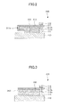
Fig. 2 is a cross-sectional view of the insulator ofFig. 1 ; -
Fig. 3 is a cross-sectional view of an insulator illustrated for comparison with the insulator ofFig. 1 ; -
Fig. 4 is a perspective view illustrating a mat member ofFig. 2 ; -
Figs. 5A through 5D are perspective views illustrating examples of cover members on which one or more triangular claws are formed; -
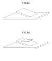
Figs. 6A through 6D are perspective views illustrating examples of cover members on which one or more quadrangular claws are formed; -
Figs. 7A and 7B are perspective views illustrating examples of cover members on which claws having a variant shape are formed; -
Fig. 8 is a perspective view illustrating a variation of the cover member ofFig. 6B ; -
Fig. 9 is a plan view illustrating a method of making the cover member ofFig. 8 ; -
Figs. 10A and 10B are perspective views illustrating the shapes of punch-pressed parts; and -
Fig. 11 is a perspective view illustrating an example of a variation of the insulator ofFig. 2 . - In the following, embodiments will be described by referring to the accompanying drawings.
-
Fig. 1 is a drawing illustrating an example of an embodiment of an internal-combustion engine exhaust system. Anexhaust system 100 of a diesel engine includes anexhaust manifold 110 through which exhaust gas from adiesel engine 200 flows, apurification apparatus 120 for purifying the exhaust gas having passed through theexhaust manifold 110, anexhaust pipe 130 through which the exhaust gas purified by thepurification apparatus 120 flows, apurification apparatus 140 for purifying the exhaust gas having passed through theexhaust pipe 130, anexhaust pipe 150 through which the exhaust gas purified by thepurification apparatus 140 flows, and amuffler 160 which discharges the exhaust gas having passed through theexhaust pipe 150. - An
insulator 310 is attached to the outer surface of theexhaust manifold 110 in a detachable manner. - As illustrated in
Fig. 2 , astud 313 is formed on acover member 311 that is made of an aluminum-coated steel plate. Amat member 312 made of silica alumina fiber is fixed to thecover member 311 by thestud 313. Theinsulator 310 is fixed to theexhaust manifold 110 such that themat member 312 is in close contact with theexhaust manifold 110 without a space therebetween. It may be noted that a side end of themat member 312 is tightly covered, without any intervening space, by afolding part 311a formed at the corresponding side end of thecover member 311. Since themat member 312 is placed in close contact with theexhaust manifold 110 without any intervening space, no gap is created between theexhaust manifold 110 and thecover member 311, thereby suppressing a temperature drop of theexhaust manifold 110. Consequently, this arrangement successfully prevents the lowering of performance of thepurification apparatuses - The
mat member 312 closely covers theexhaust manifold 110 without any intervening space even if theexhaust manifold 110 has a complex shape. This suppresses the lowering of temperature of theexhaust manifold 110. - In an arrangement illustrated in
Fig. 3 for comparison purposes, thestud 313 is not used, and astainless steel mesh 313' fixed to thecover member 311 by spot welding is used instead. Themat member 312 is held between thecover member 311 and themesh 313', with a gap created between theexhaust manifold 110 and thecover member 311. This causes the temperature of theexhaust manifold 110 to drop. As a consequence, the performance of exhaust gas purification is lowered. - In
Fig. 2 , thecover member 311 has the foldingpart 311a formed at the side end thereof, which prevents themat member 312 from falling off from the side end. Further, thecover member 311 has abolt hole 311b formed at the side end opposite to the side end at which thefolding part 311a is formed. - The material of the
cover member 311 is not limited to a particular material as long as thecover member 311 can be shaped to match the shape of theexhaust manifold 110. Thecover member 311 may be made of iron, aluminum, copper, stainless steel, or the like. - The thickness of the
cover member 311 is not limited to a particular thickness as long as it exhibits sufficient strength to avoid damage caused by engine vibration. The thickness may typically be 0.1 to 0.6 mm. - Surface treatment such as embossing and nimbus may be applied in order to improve the strength of the
cover member 311. Further, two or more plates may be combined together for strength improvement. - As illustrated in
Fig. 4 , themat member 312 may haveconfounding points 312a formed by needling, which is performed from both the upper surface and the lower surface in a direction that is not included in either the yz plane or the zx plane. The z axis is defined as the thickness direction. With the confoundingpoints 312a, themat member 312 is more securely entangled with thestud 313. - The density of the confounding
points 312a of themat member 312 may typically be 20 per cm2. It may preferably be in the range of 5 to 25 per cm2. - In the following, an example of the method of producing the
mat member 312 will be described. - An aqueous solution of basic aluminum chloride is prepared such that the contained amount of aluminum is 70 g/l, and the atomic ratio of aluminum to chloride is 1.8. Silica sol is added to the solution such that the composition ratio of alumina to silica is 60-80:40-20, and is more preferably 70-74:30-26. A composition ratio of alumina of 60% or less results in a small composition ratio of mullite generated from alumina and silica, thereby raising the thermal conductivity of the
mat member 312 and thus providing insufficient thermal insulation. - Subsequently, resin such as polyvinyl alcohol is added, followed by a condensing process to prepare spinning liquid. The spinning liquid is then used in fiber spinning performed by the blowing method.
- The blowing method performs fiber spinning by using an air flow spurting from an air nozzle and a spinning liquid flow discharged from a spinning liquid nozzle. The speed of gas flow from the air nozzle per slit may typically be 40 to 200 m/second. The diameter of the spinning liquid nozzle may typically be 0.1 to 0.5 mm. The amount of spinning liquid supply per spinning liquid nozzle may typically be 1 to 120 ml/hour, and may preferably be 3 to 50 ml/hour. Under the conditions described above, spinning liquid discharged from the spinning liquid nozzle is sufficiently extended, and does not exhibit excessive adhesiveness. A sheet of silica alumina fiber precursor is thus obtained that has relatively uniform fiber diameters.
- An average fiber length of the silica alumina fiber precursor may typically be no shorter than 250 micrometers, and may preferably be no shorter than 500 micrometers. An average fiber length shorter than 250 micrometers means that silica alumina fiber precursors is not sufficiently entangled, thereby providing insufficient strength. A diameter of the silica alumina fiber precursor may typically be 3 to 8 micrometers, and may preferably be 5 to 7 micrometers.
- After the layers of silica alumina fiber precursor are stacked one over another, a needling apparatus is used to perform needling by which needles are inserted into and removed from the multilayer sheet. The needling apparatus has needles arranged in such a direction as previously described. The needling apparatus also has two needle boards that move back and forth for the purpose of insertion and removal of the needles, and has a pair of support plates that support the multilayer sheet. The needles on the needle board are arranged at a density of 25 to 5000 per 100 cm2, for example. The pair of support plates has through-holes formed therein at the positions coinciding the positions of the needles formed on the two needle board. The two needle boards serve to perform needling with respect to the front surface and back surface of the multilayer sheet, respectively. The needles formed on the two needle boards are arranged such that their needling positions do not coincide with each other. The two needle boards are moved back and forth relative to the multilayer sheet held by the support plates, thereby causing the needles to be inserted into and removed from the multilayer sheet to create confounding points at which fibers are confounded (i.e., entangled). Fibers entangled in a complex fashion are oriented in the same direction at the confounding points, so that the strength of the multilayer sheet is improved.
- The needling apparatus may be provided with a conveyor unit that conveys the multilayer sheet at a speed of 20 mm/second, for example.
- The post-needling multilayer sheet is heated up from room temperature and burnt at the maximum temperature of approximately 1250 degrees Celsius for some duration, thereby producing the
mat member 312 comprised of silica alumina fiber. - The produced
mat member 312 has needling traces at which silica alumina fibers are locally, tightly entangled. The needle traces are entangled with thestud 313, the claw, or the hook, which will be described layer. Themat member 312 is thus fixed to theinsulator 310 in a secure manner. With this provision, themat member 312 is unlikely to fall off when theinsulator 310 is attached to or detached from theexhaust manifold 110. - The material of the
mat member 312 is not limited to silica alumina fiber as long as it can suppress the lowering of temperature of theexhaust manifold 110. The material may be any one of or combination of alumina fiber, silica fiber, ceramic fiber such as rock wool, glass fiber, and the like. A fiber that contains no fewer than 50 mass % of alumina may preferably be used because of its ability to suppress fiber scattering and shape distortion. - The thickness of the
mat member 312 may typically be 5 to 10 mm, more or less. - The bulk density of the
mat member 312 may preferably be 0.15 to 0.55 g/cm3. A bulk density smaller than 0.15 g/cm3 means that a gap may appear between theexhaust manifold 110 and thecover member 311, thereby failing to suppress the lowering of temperature of theexhaust manifold 110. Bulk density exceeding 0.55 g/cm3 may mean that theinsulator 310 is not easily assembled to theexhaust manifold 110, and that themat member 312 is easily damaged. - In order to prevent an air current from intruding between the
exhaust manifold 110 and thecover member 311, it is preferable to provide no space between theexhaust manifold 110 and thecover member 311. However, there is no need to avoid any kind of space between theexhaust manifold 110 and thecover member 311 across the entire area of theinsulator 310. It suffices to avoid a space between theexhaust manifold 110 and thecover member 311 at the end (i.e., perimeter) of theinsulator 310. In consideration of this, it is preferable to provide a larger bulk density in the end portion (i.e., perimeter portion) of themat member 312 than in the center portion thereof. - The
stud 313 may preferably be bonded to thecover member 311 such that its tip is located at a predetermined distance from theexhaust manifold 110 in order to avoid the lowering of temperature of theexhaust manifold 110. The distance between thestud 313 and theexhaust manifold 110 may preferably be larger than or equal to 0.5 mm. A distance shorter than 0.5 mm between thestud 313 and theexhaust manifold 110 may cause thestud 313 to come in contact with theexhaust manifold 110 due to vibration. This may make it difficult to suppress the lowering of temperature of theexhaust manifold 110. - The diameter of the
stud 313 may typically be no shorter than 2 mm, and may preferably be 2 to 10 mm. A diameter of thestud 313 shorter than 2 mm may provide insufficient strength. - The
insulator 310 may be manufactured by fixedly mounting themat member 312 to thecover member 311 by use of thestud 313 and then by folding a side end of thecover member 311 to make thefolding part 311a. - It may be noted that the
mat member 312 may be fixedly mounted to a cover member on which a claw is formed, instead of thecover member 311 on which thestud 313 is formed. - The shape of a claw is not limited to a particular shape as long as it can securely fix the
mat member 312. The claw may be a triangular plate, a quadrangular plate, a trapezoidal plate, or the like. -
Figs. 5A through 5D ,Figs. 6A through 6D , andFigs. 7A and 7B illustrate examples of cover members on which a triangular plate claw, a quadrangular plate claw, and a claw of some other shape are formed, respectively. The claws illustrated inFigs. 5B and5D ,Figs. 6B and6D , andFig. 7B have a hook part formed thereon. The shape of a hook part is not limited to a particular shape as long as it can fixedly fix themat member 312. The hook part may be a triangular plate, a quadrangular plate, a trapezoidal plate, or the like. - The cover member illustrated in
Fig. 6B , for example, may be formed by fixedly mounting a quadrangular claw to a flat plate by welding and by fixedly mounting a quadrangular hook part to the claw by welding. - Other cover members, different from the cover member of
Fig. 6B , may be manufactured similarly to the manner described above. - The claw may preferably be formed such that its tip is located at a predetermined distance from the
exhaust manifold 110 in order to avoid the lowering of temperature of theexhaust manifold 110. The distance between the claw and theexhaust manifold 110 may preferably be larger than or equal to 0.5 mm. A distance shorter than 0.5 mm between the claw and theexhaust manifold 110 may cause the claw to come in contact with theexhaust manifold 110 due to vibration. This may make it difficult to suppress the lowering of temperature of theexhaust manifold 110. - The surface area size of the claw may typically be 5 to 10 cm2, more or less. An insufficient surface area size of the claw may result in difficulty in fixing the
mat member 312. An excessively large surface area size of the claw may result in failing to suppress the lowering of temperature of theexhaust manifold 110. - Two or more claws may be formed on a cover member. Two or more hook parts may be formed on a claw.
-
Fig. 8 is a drawing illustrating a variation of the cover member ofFig. 6B . This cover member may be made by cutting a flat plate along solid lines illustrated inFig. 9 and then by folding the inner parts at dotted lines. This requires no welding, thereby allowing easy manufacturing. Further, the angles at which the claw and hook part are arranged can be easily adjusted, which allows themat member 312 to be easily fixed. - Other cover member variations, different from the cover member of
Fig. 9 , may be manufactured similarly to the manner described above. - It may be noted that the
mat member 312 may be fixedly mounted to a cover member that is punch pressed, instead of thecover member 311 on which thestud 313 is formed. - The punch-pressed shape is not limited to a particular shape as long as it can securely fix the
mat member 312. Examples of such a shape are illustrated inFigs. 10A and 10B . - The punch-pressed part may preferably be formed such that its tip is located at a predetermined distance from the
exhaust manifold 110 in order to avoid the lowering of temperature of theexhaust manifold 110. The distance between the punch-pressed part and theexhaust manifold 110 may preferably be larger than or equal to 0.5 mm. A distance shorter than 0.5 mm between the punch-pressed part and theexhaust manifold 110 may cause the punch-pressed part to come in contact with theexhaust manifold 110 due to vibration. This may make it difficult to suppress the lowering of temperature of theexhaust manifold 110. -
Fig. 11 is a drawing illustrating a variation of theinsulator 310. An insulator 310' is configured such that ajoint member 314 made of stainless steel fiber is fixed to thecover member 311 by stop welding W, and such that themat member 312 is bound to thejoint member 314. Themat member 312 has a gap (i.e., opening) for the purpose of the spot welding W. This gap disappears when the insulator 310' is attached to theexhaust manifold 110. This suppresses the lowering of temperature of theexhaust manifold 110. - The mechanism for binding the
mat member 312 to thejoint member 314 is not limited to a particular mechanism as long as it exhibits sufficient heat-resistant characteristics. For example, needling, stitching, stapling, or the like may be used. - The material of the
joint member 314 is not limited to stainless steel fiber as long as it can be fixed to thecover member 311 by spot welding W. The material may be another metal fiber such as iron fiber, aluminum fiber, or copper fiber, or may be a combination of two or more of these fibers. Particularly, iron fiber or stainless steel fiber may be preferable since the use of such a fiber allows the insulator 310' to be fixed by welding to an exhaust pipe such as theexhaust manifold 110. - The specific weight of the
joint member 314 is not limited to a particular value as long as themat member 312 can be bound to thejoint member 314. The specific weight may typically be 300 to 1500 g/m2, and may preferably be approximately 1000 g/m2 . - The insulator 310' may be manufactured by binding the
mat member 312 to thejoint member 314 and then by fixing thejoint member 314 together with themat member 312 to thecover member 311 by spot welding W. - The
exhaust manifold 110 to which theinsulator 310 is attached has a mountingpart 111 at the end opposite to the end that faces thefolding part 311a of thecover member 311. Abolt hole 111a is formed in this mountingpart 111. Abolt 112 is used to mount theinsulator 310 on theexhaust manifold 110 in a detachable manner. - The
purification apparatus 120 includes acarrier 121 carrying a diesel oxidation catalyst (DOC) and a diesel particulate filter (DPF) 122 around which a support seal member is arranged, all of which are accommodated in ametal container 123. The diesel oxidization catalyst oxidizes carbon monoxide (CO) and carbon hydride (HC) contained in exhaust gas. The diesel particulate filter catches particle matter (PM) contained in exhaust gas, and lets it burn. - An
insulator 320 is attached to the outer surface of thepurification apparatus 120 in a detachable manner. Theinsulator 320 may be the same as or similar to theinsulator 310, and can be mounted in a detachable manner similar to the manner in which theinsulator 310 is mounted. This arrangement suppresses the lowering of temperature of thepurification apparatus 120, thereby avoiding the lowering of catalytic functions of both thepurification apparatus 120 and thepurification apparatus 140, which will be described later. - An
insulator 330 is attached to the outer surface of theexhaust pipe 130 in a detachable manner. Theinsulator 330 may be the same as or similar to theinsulator 310, and can be mounted in a detachable manner similar to the manner in which theinsulator 310 is mounted. This arrangement suppresses the lowering of temperature of theexhaust pipe 130, thereby avoiding the lowering of catalytic function of thepurification apparatus 140, which will be described later. - The
purification apparatus 140 performs selective catalytic reduction with respect to NOx. Thepurification apparatus 140 includes acatalyst carrier 141 around which a support seal member is arranged, all of which are accommodated in ametal container 142. It may be noted that aqueous urea solution together with compressed air is spurted into theexhaust pipe 130 situated immediately upstream relative to thepurification apparatus 140 to be mixed with exhaust gas. - An
insulator 340 is attached to the outer surface of thepurification apparatus 140 in a detachable manner. Theinsulator 340 may be the same as or similar to theinsulator 310, and can be mounted in a detachable manner similar to the manner in which theinsulator 310 is mounted. This arrangement suppresses the lowering of temperature of thepurification apparatus 140, thereby avoiding the lowering of catalytic function of thepurification apparatus 140. - In the present embodiment, the
insulators exhaust manifold 110, thepurification apparatus 120, theexhaust pipe 130, and thepurification apparatus 140, respectively. Alternatively, at least one but not all of theinsulators - A turbo charger may be provided in which the energy of exhaust gas passing through the
exhaust manifold 110 is utilized to rotate a turbine thereby to drive a centrifugal compressor. The turbo charger then supplies the compressed air to thediesel engine 200. - An insulator is attached to the outer surface of the turbo charger in a detachable manner. The insulator may be the same as or similar to the
insulator 310, and can be mounted in a detachable manner similar to the manner in which theinsulator 310 is mounted. This arrangement suppresses the lowering of temperature of the turbo charger, thereby allowing the energy of exhaust gas to be efficiently utilized, and also avoiding the lowering of catalytic functions of thepurification apparatuses - An exhaust gas recirculation may be provided by which part of the exhaust gas passing through the
exhaust manifold 110 is extracted and supplied to an intake manifold for second-time intake. - In the present embodiment, the
exhaust system 100 has been described as that of a diesel engine. This is a non-limiting example, and the exhaust system is not limited to that of a particular type of engine. It may be an exhaust system of a gasoline engine. - The
mat member 312 having a size of 100 mm x 100 mm x 4 mm and made of alumina fiber was used. Thejoint member 314 was stainless steel fiber (SUS434), which had a size of 100 mm x 100 mm and a specific weight of 300 to 1500 g/m2. Needling was performed at 350 needling points per cm2 from the joint-member side toward the mat member side, thereby binding thejoint member 314 and themat member 312. Thejoint member 314 bound to themat member 312 was fixed by spot welding W to thecover member 311 made of a stainless steel plate (SUS409) having a size of 100 mm x 100 mm x 1.5 mm, thereby producing the insulator 310' (seeFig. 9 ). - The insulator 310' was obtained in the same manner as in the first example, except that the
mat member 312 was bound to thejoint member 314 by stitching at 3-mm intervals using a metal fiber that is 0.2 mm in diameter. - A mat member having a size of 100 mm x 100 mm x 4 mm and made of alumina fiber was placed on a cover member that was a stainless steel plate (SUS409) having a size of 100 mm x 100 mm x 1.5 mm. Further, a plain-woven mesh in which metal fibers having a diameter of 0.2 mm were provided at 0.50-mm intervals was placed on top of the mat member. Spot welding was then performed to fix them together to produce an insulator.
- A mat member having a size of 100 mm x 100 mm x 4 mm and made of alumina fiber was fixed by an adhesive agent to a cover member that was a stainless steel plate (SUS409) having a size of 100 mm x 100 mm x 1.5 mm, thereby producing an insulator. The adhesive agent was ARON CERAMIC D (manufactured by TOAGOSEI CO., LTD).
- A stainless steel plate (SUS409) having a size of 100 mm x 100 mm x 1.5 mm and an insulator were successively placed on a hotplate CH-180 (manufactured by ASONE). A thermocouple was used to measure a difference in temperature between the front surface and back surface of the stainless steel when the hotplate was set equal to 300 degrees Celsius. A household electrical fan DF35A (manufactured by Toshiba Corporation) on the WEAK setting was used to blow air to the heater from a distance of 1 m and from a height of 60 cm. Heat insulation was checked by comparing a difference between the front-and-back-surface temperature difference obtained in the presence of blowing air and the front-and-back-surface temperature difference in the absence of blowing air.
- Such a test on heat insulation serves to evaluate the effect of suppressing the lowering of temperature with respect to an exhaust system of an internal-combustion engine when such lowering occurs due to an air current flowing into a gap between the cover member and the mat member.
- Strength against heat was evaluated by performing 10 thermal cycles, each of which included keeping the insulator at 600 degrees Celsius for one hour and then cooling it down to room temperature. Check results were either "OK" for the case in which the mat member did not fall off upon lifting the cover member or "NG" for the case in which the mat member fell off upon lifting the cover member.
- Table 1 shows the results of evaluations.
TABLE 1 Heat Insulation Strength against Heat Temperature Deference [°C] Difference in Temperature Deference [°C] Air Blow No Air Blow Example 1 79 81 2 OK Example 2 83 88 5 OK Comparative Example 1 118 148 30 OK Comparative Example 2 74 78 4 NG - Further, the present invention is not limited to these embodiments, but various variations and modifications may be made without departing from the scope of the present invention.
Claims (9)
- An insulator for an exhaust system of an internal-combustion engine, characterized in that a mat member made of material including at least one of ceramic fibers and glass fibers is fixed to a cover member to form an inner surface.
- The insulator as claimed in claim 1, wherein the mat member is fixed to the cover member by a stud.
- The insulator as claimed in claim 1, wherein a claw is formed on the cover member, and the mat member is fixed to the cover member by the claw.
- The insulator as claimed in claims 2 or 3, wherein the mat member has needle traces.
- The insulator as claimed in claim 1, wherein a joint member inclusive of metal fiber is fixed to the cover member by welding, and the mat member is bound to the joint member.
- The insulator as claimed in claim 5, wherein the mat member is bound to the joint member through one of needling, stitching, and stapling.
- The insulator as claimed in claim 5 or 6, wherein the metal fibers include at least one of iron, aluminum, copper, and stainless steel.
- The insulator as claimed in any one of claims 1 to 7, wherein the ceramic fibers include at least one of alumina, silica, silica alumina, and rock wool.
- An exhaust system for an internal-combustion engine, comprising the insulator of any one of claims 1 to 8, such that the mat member is in contact with the exhaust system.
Applications Claiming Priority (1)
| Application Number | Priority Date | Filing Date | Title |
|---|---|---|---|
| JP2010012502A JP2011149371A (en) | 2010-01-22 | 2010-01-22 | Insulator and exhaust system for internal-combustion engine |
Publications (2)
| Publication Number | Publication Date |
|---|---|
| EP2348206A2 true EP2348206A2 (en) | 2011-07-27 |
| EP2348206A3 EP2348206A3 (en) | 2014-03-26 |
Family
ID=43801730
Family Applications (1)
| Application Number | Title | Priority Date | Filing Date |
|---|---|---|---|
| EP20110151362 Withdrawn EP2348206A3 (en) | 2010-01-22 | 2011-01-19 | Insulator and exhaust system of internal-combustion engine |
Country Status (3)
| Country | Link |
|---|---|
| US (1) | US9091198B2 (en) |
| EP (1) | EP2348206A3 (en) |
| JP (1) | JP2011149371A (en) |
Cited By (1)
| Publication number | Priority date | Publication date | Assignee | Title |
|---|---|---|---|---|
| EP2781712A1 (en) * | 2013-03-18 | 2014-09-24 | Eberspächer Exhaust Technology GmbH & Co. KG | Insulation means |
Families Citing this family (4)
| Publication number | Priority date | Publication date | Assignee | Title |
|---|---|---|---|---|
| DE102013107495A1 (en) * | 2013-07-15 | 2015-01-15 | Elringklinger Ag | shielding |
| USD745568S1 (en) * | 2013-10-25 | 2015-12-15 | Alex Lentz | Triangular plate for motor frame |
| DE102015016977A1 (en) * | 2015-12-24 | 2017-06-29 | Audi Ag | Method and device for improving an exhaust gas behavior of an internal combustion engine |
| JP6744740B2 (en) * | 2016-03-28 | 2020-08-19 | 日鉄ステンレス株式会社 | Ferritic stainless steel plate for exhaust manifold |
Citations (2)
| Publication number | Priority date | Publication date | Assignee | Title |
|---|---|---|---|---|
| JPH0949426A (en) | 1995-08-07 | 1997-02-18 | Nichias Corp | Insulator for exhaust system of internal combustion engine |
| JP2005098209A (en) * | 2003-09-25 | 2005-04-14 | Nippon Packing Kogyo Kk | Heat insulation cover |
Family Cites Families (22)
| Publication number | Priority date | Publication date | Assignee | Title |
|---|---|---|---|---|
| US1915611A (en) * | 1930-06-14 | 1933-06-27 | Miller William Lott | Insulating slab |
| US3553920A (en) * | 1967-07-10 | 1971-01-12 | Stephen F Cole Jr | Insulation modules for insulating wall surfaces |
| US3927443A (en) * | 1971-08-13 | 1975-12-23 | Ingrip Fasteners | Multi-element self-gripping devices with linguiform gripping tabs |
| US4180890A (en) * | 1972-05-23 | 1980-01-01 | Ingrip Fasteners, Inc. | Linear element with grafted nibs and method therefor |
| US4265953A (en) * | 1979-03-07 | 1981-05-05 | Minnesota Mining And Manufacturing Company | Intumescent stressed skin composite material |
| US4512130A (en) * | 1982-03-22 | 1985-04-23 | Pepin Jean P | Insulation support |
| US4911972A (en) * | 1988-08-12 | 1990-03-27 | Union Carbide Corporation | Insulating composite gasket |
| US5181319A (en) * | 1992-01-09 | 1993-01-26 | Campbell Frank Jun | Squeeze-on insulation for reheating furnace water cooled skid systems |
| US6465100B1 (en) * | 1993-06-15 | 2002-10-15 | Alliant Techsystems Inc. | Densification of composite preforms by liquid resin infiltration assisted by rigid-barrier actinic gelation |
| JP3020812B2 (en) * | 1993-09-03 | 2000-03-15 | イビデン株式会社 | Sound and heat insulation structure |
| US6251498B1 (en) * | 1993-09-03 | 2001-06-26 | Ibiden Co., Ltd. | Soundproof heat shield member for exhaust manifold |
| US5656353A (en) * | 1995-06-27 | 1997-08-12 | Tba Composites, Inc. | Laminated heat shield with prongs and method of manufacturing same |
| US5980665A (en) * | 1996-05-31 | 1999-11-09 | The Boeing Company | Z-pin reinforced bonds for connecting composite structures |
| EP0992659B1 (en) | 1998-10-05 | 2007-05-02 | Scambia Industrial Developments Aktiengesellschaft | Exhaust pipe element and method for producing an exhaust pipe element |
| JP4290376B2 (en) * | 2002-03-20 | 2009-07-01 | ニチアス株式会社 | Soundproof insulation and method for producing the same |
| US20020168492A1 (en) * | 2001-03-30 | 2002-11-14 | Nichias Corporation | Sound and heat insulating material and method for manufacturing the same and articles made thereof |
| DE10125559A1 (en) * | 2001-05-23 | 2002-11-28 | Basf Ag | Composite component manufacturing method, involves compression of a punched edge on a metal component into a plastic component to form a connection |
| US7013536B2 (en) * | 2002-10-19 | 2006-03-21 | General Motors Corporation | Releasable fastener systems and processes |
| JP2005344968A (en) * | 2004-06-01 | 2005-12-15 | Sanritsu Hybrid Kk | Heat exchanging structure and heat insulating structure using non-woven metal tissue |
| JP2006250054A (en) | 2005-03-11 | 2006-09-21 | Toyota Motor Corp | Sound insulation structure of internal combustion engine |
| US20080169038A1 (en) * | 2007-01-11 | 2008-07-17 | Timothy David Sellis | Thermal shield and methods of construction and installation |
| MX2010002173A (en) * | 2007-08-31 | 2010-03-18 | Unifrax I Llc | Exhaust gas treatment device. |
-
2010
- 2010-01-22 JP JP2010012502A patent/JP2011149371A/en active Pending
-
2011
- 2011-01-13 US US13/005,662 patent/US9091198B2/en active Active
- 2011-01-19 EP EP20110151362 patent/EP2348206A3/en not_active Withdrawn
Patent Citations (2)
| Publication number | Priority date | Publication date | Assignee | Title |
|---|---|---|---|---|
| JPH0949426A (en) | 1995-08-07 | 1997-02-18 | Nichias Corp | Insulator for exhaust system of internal combustion engine |
| JP2005098209A (en) * | 2003-09-25 | 2005-04-14 | Nippon Packing Kogyo Kk | Heat insulation cover |
Cited By (2)
| Publication number | Priority date | Publication date | Assignee | Title |
|---|---|---|---|---|
| EP2781712A1 (en) * | 2013-03-18 | 2014-09-24 | Eberspächer Exhaust Technology GmbH & Co. KG | Insulation means |
| US9671056B2 (en) | 2013-03-18 | 2017-06-06 | Eberspächer Exhaust Technology GmbH & Co. KG | Insulation |
Also Published As
| Publication number | Publication date |
|---|---|
| JP2011149371A (en) | 2011-08-04 |
| US9091198B2 (en) | 2015-07-28 |
| US20110180174A1 (en) | 2011-07-28 |
| EP2348206A3 (en) | 2014-03-26 |
Similar Documents
| Publication | Publication Date | Title |
|---|---|---|
| US9494071B2 (en) | Mounting mat for mounting monolith in a pollution control device | |
| CN1678821B (en) | Mat for mounting a pollution control element in a pollution control device for the treatment of exhaust gas | |
| US6613294B2 (en) | Hybrid mounting system for pollution control devices | |
| CN100386507C (en) | Catalyst converter and diesel particulate filtration system | |
| EP2594758B1 (en) | Holding sealing material, method for producing the holding sealing material, and exhaust gas purifying apparatus | |
| KR101132587B1 (en) | Mat product, manufacturing method of the mat product, exhaust gas treating apparatus, and muffler apparatus | |
| JP2005074243A (en) | Contamination controlling element-holding material and contamination controlling apparatus | |
| US9091198B2 (en) | Insulator and exhaust system of internal-combustion engine | |
| JP2009085092A (en) | Mat material, exhaust gas treatment device and silencer | |
| US20140290228A1 (en) | Holding sealing material for exhaust gas purifying apparatus, method for manufacturing holding sealing material, exhaust gas purifying apparatus, and method for manufacturing exhaust gas purifying apparatus | |
| US7854904B2 (en) | Mounting mat for a catalytic converter | |
| JP5164633B2 (en) | Exhaust gas treatment device and manufacturing method thereof | |
| CN102264967B (en) | Mounting mat and pollution control equipment using the same | |
| EP2386739B1 (en) | Mat, method for producing the mat, and exhaust gas purifying apparatus with the mat | |
| EP4596853A1 (en) | Mat material, exhaust gas purification device, and method for manufacturing mat material | |
| US9290866B2 (en) | Mounting mat and pollution control device with the same | |
| WO2005003530A1 (en) | Mounting mat for a catalytic converter | |
| JP7848205B2 (en) | Mat material, exhaust gas purification device, and method for manufacturing mat material | |
| US9217357B2 (en) | Method of producing an insulated exhaust device | |
| US9924564B2 (en) | Heated mat and exhaust gas treatment device | |
| US20140290227A1 (en) | Holding sealing material, method for manufacturing holding sealing material, exhaust gas purifying apparatus, and method for manufacturing exhaust gas purifying apparatus | |
| EP2770179A1 (en) | Mat material and exhaust gas purification device | |
| EP1832729A1 (en) | Fiber sheet member and exhaust gas purifying device using the same as a support mat | |
| EP2837787A1 (en) | Holding material for gas-processing device, gas-processing device, and method relating to same | |
| JP7319051B2 (en) | Holding material and exhaust gas purification device |
Legal Events
| Date | Code | Title | Description |
|---|---|---|---|
| PUAI | Public reference made under article 153(3) epc to a published international application that has entered the european phase |
Free format text: ORIGINAL CODE: 0009012 |
|
| 17P | Request for examination filed |
Effective date: 20110119 |
|
| AK | Designated contracting states |
Kind code of ref document: A2 Designated state(s): AL AT BE BG CH CY CZ DE DK EE ES FI FR GB GR HR HU IE IS IT LI LT LU LV MC MK MT NL NO PL PT RO RS SE SI SK SM TR |
|
| AX | Request for extension of the european patent |
Extension state: BA ME |
|
| PUAL | Search report despatched |
Free format text: ORIGINAL CODE: 0009013 |
|
| AK | Designated contracting states |
Kind code of ref document: A3 Designated state(s): AL AT BE BG CH CY CZ DE DK EE ES FI FR GB GR HR HU IE IS IT LI LT LU LV MC MK MT NL NO PL PT RO RS SE SI SK SM TR |
|
| AX | Request for extension of the european patent |
Extension state: BA ME |
|
| RIC1 | Information provided on ipc code assigned before grant |
Ipc: F16L 59/02 20060101ALI20140218BHEP Ipc: F01N 13/14 20100101AFI20140218BHEP |
|
| 17Q | First examination report despatched |
Effective date: 20161205 |
|
| STAA | Information on the status of an ep patent application or granted ep patent |
Free format text: STATUS: THE APPLICATION IS DEEMED TO BE WITHDRAWN |
|
| 18D | Application deemed to be withdrawn |
Effective date: 20190302 |