EP2347954A1 - A bracket for attaching an electrical cable to a vehicle - Google Patents
A bracket for attaching an electrical cable to a vehicle Download PDFInfo
- Publication number
- EP2347954A1 EP2347954A1 EP11151595A EP11151595A EP2347954A1 EP 2347954 A1 EP2347954 A1 EP 2347954A1 EP 11151595 A EP11151595 A EP 11151595A EP 11151595 A EP11151595 A EP 11151595A EP 2347954 A1 EP2347954 A1 EP 2347954A1
- Authority
- EP
- European Patent Office
- Prior art keywords
- cable
- bracket
- tie
- vehicle
- abutment portion
- Prior art date
- Legal status (The legal status is an assumption and is not a legal conclusion. Google has not performed a legal analysis and makes no representation as to the accuracy of the status listed.)
- Granted
Links
- 239000002828 fuel tank Substances 0.000 claims abstract description 32
- 238000000034 method Methods 0.000 claims description 5
- 239000012777 electrically insulating material Substances 0.000 claims description 2
- 239000002131 composite material Substances 0.000 description 5
- 229910000838 Al alloy Inorganic materials 0.000 description 4
- 239000004677 Nylon Substances 0.000 description 4
- 239000004697 Polyetherimide Substances 0.000 description 4
- 230000000694 effects Effects 0.000 description 4
- 229920001778 nylon Polymers 0.000 description 4
- 229920001601 polyetherimide Polymers 0.000 description 4
- 239000000853 adhesive Substances 0.000 description 3
- 230000001070 adhesive effect Effects 0.000 description 3
- 239000000446 fuel Substances 0.000 description 3
- 239000011810 insulating material Substances 0.000 description 3
- 238000004026 adhesive bonding Methods 0.000 description 2
- 239000003365 glass fiber Substances 0.000 description 2
- 239000000463 material Substances 0.000 description 2
- 239000004033 plastic Substances 0.000 description 2
- 229920003023 plastic Polymers 0.000 description 2
- 239000004696 Poly ether ether ketone Substances 0.000 description 1
- 239000004411 aluminium Substances 0.000 description 1
- 229910052782 aluminium Inorganic materials 0.000 description 1
- XAGFODPZIPBFFR-UHFFFAOYSA-N aluminium Chemical compound [Al] XAGFODPZIPBFFR-UHFFFAOYSA-N 0.000 description 1
- 239000011248 coating agent Substances 0.000 description 1
- 238000000576 coating method Methods 0.000 description 1
- 230000003247 decreasing effect Effects 0.000 description 1
- 238000005553 drilling Methods 0.000 description 1
- 238000010616 electrical installation Methods 0.000 description 1
- 238000009434 installation Methods 0.000 description 1
- 239000000314 lubricant Substances 0.000 description 1
- 239000002184 metal Substances 0.000 description 1
- 229910052751 metal Inorganic materials 0.000 description 1
- 239000007769 metal material Substances 0.000 description 1
- 230000000284 resting effect Effects 0.000 description 1
- 238000003466 welding Methods 0.000 description 1
Images






Classifications
-
- H—ELECTRICITY
- H02—GENERATION; CONVERSION OR DISTRIBUTION OF ELECTRIC POWER
- H02G—INSTALLATION OF ELECTRIC CABLES OR LINES, OR OF COMBINED OPTICAL AND ELECTRIC CABLES OR LINES
- H02G3/00—Installations of electric cables or lines or protective tubing therefor in or on buildings, equivalent structures or vehicles
- H02G3/30—Installations of cables or lines on walls, floors or ceilings
- H02G3/32—Installations of cables or lines on walls, floors or ceilings using mounting clamps
-
- B—PERFORMING OPERATIONS; TRANSPORTING
- B60—VEHICLES IN GENERAL
- B60R—VEHICLES, VEHICLE FITTINGS, OR VEHICLE PARTS, NOT OTHERWISE PROVIDED FOR
- B60R16/00—Electric or fluid circuits specially adapted for vehicles and not otherwise provided for; Arrangement of elements of electric or fluid circuits specially adapted for vehicles and not otherwise provided for
- B60R16/02—Electric or fluid circuits specially adapted for vehicles and not otherwise provided for; Arrangement of elements of electric or fluid circuits specially adapted for vehicles and not otherwise provided for electric constitutive elements
- B60R16/0207—Wire harnesses
- B60R16/0215—Protecting, fastening and routing means therefor
-
- B—PERFORMING OPERATIONS; TRANSPORTING
- B64—AIRCRAFT; AVIATION; COSMONAUTICS
- B64C—AEROPLANES; HELICOPTERS
- B64C1/00—Fuselages; Constructional features common to fuselages, wings, stabilising surfaces or the like
- B64C1/40—Sound or heat insulation, e.g. using insulation blankets
- B64C1/403—Arrangement of fasteners specially adapted therefor, e.g. of clips
- B64C1/406—Arrangement of fasteners specially adapted therefor, e.g. of clips in combination with supports for lines, e.g. for pipes or cables
-
- Y—GENERAL TAGGING OF NEW TECHNOLOGICAL DEVELOPMENTS; GENERAL TAGGING OF CROSS-SECTIONAL TECHNOLOGIES SPANNING OVER SEVERAL SECTIONS OF THE IPC; TECHNICAL SUBJECTS COVERED BY FORMER USPC CROSS-REFERENCE ART COLLECTIONS [XRACs] AND DIGESTS
- Y02—TECHNOLOGIES OR APPLICATIONS FOR MITIGATION OR ADAPTATION AGAINST CLIMATE CHANGE
- Y02T—CLIMATE CHANGE MITIGATION TECHNOLOGIES RELATED TO TRANSPORTATION
- Y02T50/00—Aeronautics or air transport
- Y02T50/40—Weight reduction
-
- Y—GENERAL TAGGING OF NEW TECHNOLOGICAL DEVELOPMENTS; GENERAL TAGGING OF CROSS-SECTIONAL TECHNOLOGIES SPANNING OVER SEVERAL SECTIONS OF THE IPC; TECHNICAL SUBJECTS COVERED BY FORMER USPC CROSS-REFERENCE ART COLLECTIONS [XRACs] AND DIGESTS
- Y10—TECHNICAL SUBJECTS COVERED BY FORMER USPC
- Y10T—TECHNICAL SUBJECTS COVERED BY FORMER US CLASSIFICATION
- Y10T29/00—Metal working
- Y10T29/49—Method of mechanical manufacture
- Y10T29/49826—Assembling or joining
- Y10T29/49947—Assembling or joining by applying separate fastener
- Y10T29/49948—Multipart cooperating fastener [e.g., bolt and nut]
- Y10T29/4995—Nonthreaded
Definitions
- the present invention concerns brackets for attaching an electrical cable to a vehicle. More particularly, but not exclusively, this invention concerns a bracket for attaching to a fuel tank of an aircraft in order to secure an electrical cable.
- the invention also concerns an electrical assembly comprising a plurality of such brackets, a fuel tank comprising a plurality of such brackets, an aircraft comprising a plurality of such brackets or such an electrical assembly or fuel tank and a method of attaching a cable to a vehicle.
- brackets are often used to securely hold electrical cable, which is part of a Fuel Quantity Indication (FQI) System of an aircraft.
- the cable has to be held within the aircraft fuel tank, generally contained within the wing of an aircraft.
- any cable must be maintained at a minimum gap of 10mm from the fuel tank structure.
- the cable must have a greater clearance from other systems. It also must remain firmly in position with the minimum possible amount of sag between brackets for the life of the aircraft.
- brackets are nylon coated aluminium and are attached to stringers and ribs of the fuel tank by drilling and riveting. Two nylon cable-ties are then used at each point of contact along the stringers/ribs to prevent the cable moving.
- the brackets In a composite wing box, the brackets must be made from a fully insulating material and metal rivets cannot be used to attach the bracket to the fuel tank. Therefore, for composite wings, the brackets used are made from a composite, insulating material, such as PEI (Polyetherimide) or glass fibre re-enforced plastic.
- PEI Polyetherimide
- the brackets are attached to the fuel tank by adhesive bonding.
- the nylon cable-ties are tightened using a torque gun (not shown) set at an appropriate torque for the cable-tie being used.
- Bracket 1a and 1b Such a bracket, with the cable and cable-tie in place, is shown in Figures 1a and 1b .
- the bracket 1 has a flat bonding face 2 at one end for attaching to a stringer 3 of the fuel tank.
- the bracket has a generally flat and square shaped cable mounting face 4.
- On each corner of the mounting face 4 is a locating bump 8.
- These locating bumps 8 provide abutment surfaces for the cable 6 to rest on or against, thereby ensuring the cable rests in a certain position on the bracket 1.
- On each side of the square face is a slot 5 for a cable-tie.
- the cable 6 is secured to the cable mounting face 4 by a cable-tie 7 looped around the cable 6 and cable mounting face 4 through two opposite cable-tie slots 5.
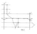
- Figure 2 shows part of a wing box layout, showing the position of the brackets and cable 6, in relation to the stringers 3 and ribs 9 of the fuel tank.
- the cable 6 is generally run along the length of the stringers 3 and is attached to the stringers at various points with a single bracket 1. These points are approximately 150 to 200mm apart. The spacing of the points is decided based on maintaining a minimum clearance distance even in the event of a cable-tie/bracket failure, and the resulting "skipping rope" effect of the cable between the brackets either side of the failure being able to swing.
- two brackets 1 are used, one either side of the stringer/rib.
- the present invention seeks to mitigate the above-mentioned problems. Alternatively or additionally, the present invention seeks to provide an improved bracket.
- the aviation fuel in the fuel tank acts as a lubricant and the over braid coating on the outside of the cable is made from a PEEK TM material, which has a low coefficient of friction. Hence, the cable can become loose very easily.
- the third region is positioned, along the path, midway between the first and second regions.
- the non-planar rear surface defines at least three points of contact for the cable-tie on the path behind the cable abutment portion, including (i) a first point of contact at the first region, (ii) a second point of contact at the second region, and (iii) a third point of contact at the third region, wherein the distance of the third point from the cable abutment portion is both greater than the distance of the first point and greater than the distance of the second point from the cable abutment portion.
- This provides a path for the cable-tie that provides for curvature of the cable-tie.
- the path provided has a radius of curvature that does not exceed the natural minimum radius of curvature of the cable-tie.
- the applicant has realised that, in the prior art brackets, the areas of high curvature of the cable-tie at the edges of the rear of the cable mounting face can cause the cable-tie to stretch over time. This reduces the tension on the cable-tie and increases slack in the cable-tie loop.
- the natural minimum radius of curvature of the cable-tie can therefore be defined as the smallest radius of curvature of the cable-tie at which deformation of the cable-tie does not occur.
- the cable-tie to be used with the bracket has a width of between 1mm and 5mm, preferably between 2mm and 4mm, most preferably approximately 3mm.
- the cable-tie to be used with the bracket has a depth of between 0 and 5mm, preferably between 1 and 2mm, most preferably approximately 1.5mm.
- the cable-tie to be used with the bracket has a length of between 200 and 300mm most preferably approximately 250mm.
- the closed loop formed by the cable-tie preferably has a perimeter of between 3 and 15 mm, preferably between 50 and 100mm.
- At least part of the non-planar rear surface has the shape of a cylinder which presents a curved convex profile, thereby defining a substantially curved path in one direction behind the cable abutment portion.
- the non-planar rear surface defines said at least three points of contact for the cable-tie on the path behind the cable abutment portion in more than one direction behind the cable abutment portion, thereby allowing the cable to be secured to the bracket in a plurality of directions with respect to the vehicle.
- the non-planar rear surface defines said at least three points of contact for the cable-tie on the path behind the cable abutment portion in more two transverse directions behind the cable abutment portion, thereby allowing the cable to be secured to the bracket in two directions transverse to each other.
- At least part of the non-planar rear surface has a profile substantially in the form of a dome.
- the dome is a substantially hemispherical dome.
- the vehicle attachment portion and the front of the cable abutment portion are offset from each other so that, in use, the bracket can extend over a step on a bracket attachment portion of the vehicle.
- the offset is between 2mm and 10mm, preferably between 4 and 8mm, most preferably approximately 6mm.
- a vehicle attachment surface of the vehicle attachment portion and the cable abutment portion are substantially perpendicular to each other. This allows the cable to be run offset from a bracket attachment point on the vehicle.
- the bracket also comprises an arm portion connecting the vehicle attachment portion and cable securing portion, the arm portion having a length such that the cable can be attached at a clearance distance from a bracket attachment surface of the vehicle.
- the bracket also comprises one or more guiding elements on or adjacent the cable abutment portion for guiding the cable into position on the cable abutment portion.
- the guiding element(s) are in the form of locating bumps extending outwards on the front of the cable abutment portion.
- the bracket is wholly made from an electrically insulating material.
- the material is PEI (Polyetherimide) or glass fibre re-enforce plastic.
- the brackets are approximately 1 to 2 inches (25 to 50mm) long.
- the path of the cable-tie over the non-planar rear surface has a radius of 7 to 10mm, but preferably, could be as large as 20mm.
- the cable radius is 1 to 20mm or larger.
- the non-planar rear surface is designed to provide a curvature on the cable-tie substantially the same as the cable radius.
- the bracket is for use on an aircraft.
- the bracket is for attaching to a fuel tank of the vehicle.
- the bracket is for use in attaching an electrical cable of a Fuel Quantity Indication (FQI) System to an inside of an aircraft fuel tank.
- the bracket is for use in a composite wing box and is designed to be attached to the aircraft by bonding.
- FQI Fuel Quantity Indication
- the invention also provides an electrical assembly comprising a plurality of brackets as described above and a cable secured to each of the brackets by a cable-tie.
- the invention also provides a stringer or rib with a plurality of brackets as described above, or an electrical assembly as described above mounted thereon.
- the invention also provides a fuel tank comprising a plurality of brackets as described above or an electrical assembly as described above or a stringer or rib as described above.
- the invention also provides an aircraft comprising a plurality of brackets as described above or an electrical assembly as described above or a stringer or rib as described above or a fuel tank as described above.
- a method of attaching a cable to a vehicle comprising the following steps providing a bracket as described above, attaching the vehicle attachment portion of the bracket to the vehicle, placing the cable on or near the front of the cable abutment portion of the bracket, and tightening a cable-tie around the cable and cable abutment portion so as to secure the cable against the cable abutment portion of the bracket.
- the cable-tie when the cable-tie is tightened, the cable-tie forms a closed loop and is held in direct contact against the third region of the non-planar rear surface.
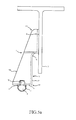
- FIGs 3a and 3b show a bracket 1 according to a first embodiment of the invention. It is similar to the prior art bracket of Figures 1a and 1b .
- the bracket 1 has a flat bonding face 2 at one end for attaching to a stringer 3 of the fuel tank.
- the bracket has a generally square shaped cable mounting face 4.
- On each corner of the mounting face 4 is a locating bump 8. These locating bumps 8 provide abutment surfaces for the cable 6 to rest on or against, thereby ensuring the cable rests in a certain position on the bracket 1.
- On each side of the square face is a slot 5 for a cable-tie.
- the cable 6 is secured to the cable mounting face 4 by a cable-tie 7 looped around the cable 6 and cable mounting face 4 through two opposite cable-tie slots 5.
- bracket of Figures 3a and 3b also comprises a nodule 10 on the back of the cable mounting face 4.
- the nodule is in the shape of a dome sat on a thin flat substantially circular disc.
- the dome of the nodule 10 has a radius of curvature of 14mm and the disc has a radius to match the base radius of the dome. Effectively, this means the nodule has straight sides near its base but a domed top.
- the cable-tie 7 When the cable 6 is secured to the cable mounting face 4, the cable-tie 7 is looped around the cable 6, cable mounting face 4 and nodule 10 and then tightened. Hence, the cable-tie 7 forms a loop around the cable 6 and nodule 10.
- the loop formed is smooth with a relatively large radius of curvature (i.e. not tightly curved) for the entire loop.
- the bracket of Figures 3a and 3b is used to attach a cable 6 along the inside of a stringer 3.
- the cable-tie 7 has a width of 3mm, a depth of 1mm and an original length of 200 to 300mm.
- the closed loop formed by the cable-tie has a perimeter of 80mm.
- the cable-tie loop is formed in the normal manner. The excess cable-tie length not forming part of the closed loop can be cut off.
- Figures 4a to 4d show a bracket 1 according to a second embodiment of the invention.
- the bracket 1 is of a different shape to the bracket of Figures 3a and 3b .
- the head portion 11 comprises a flat bonding face 2 for attaching to a stringer 3 of the fuel tank using adhesive.
- the bonding face 2 has a thickness of 2mm and is in the form of a round-cornered rectangle. The dimensions of the rectangle are 20 by 30mm.
- two sloping walls 14 extend upwards.
- the walls 14 have a thickness of 2mm.
- the walls 14 are sloped such that their height from the face 2 increases as they move away from the head portion end of the bracket 1.
- an indent step 16 is formed so as to effectively raise the height of the face 2.
- This stepped face 17 continues away from the head portion 11 and effectively shortens the height of the sloping walls 14.
- the face 17 and sloping walls 14 extend away from the head portion 11 to form an arm portion 12.
- the arm potion 12 is in the form of a channel.
- the bracket has a generally square shaped cable mounting face 4 facing outwards, away from the bracket 1, to effectively close off the channel of the arm portion 12.
- the cable mounting face 4 has a thickness of 2mm and is at 90 degrees to the angle of the flat bonding face 2.
- the cable mounting face is an 18mm by 18mm square shape.
- each side of the square face 4 is a slot 5 for a cable-tie.
- the slot On the three sides of the face 4 adjacent the stepped face 17 or the two sloping walls 14, the slot also extends slightly down the arm portion 12 on the face 17 and walls 14 so as to form corner cut-outs.
- the slots extend 7mm in length down each wall 14 and face 17 and extend 4mm into each side of the cable mounting face 4.
- the slots 5 each have a width of 5.2mm.
- a nodule 10 In between the slots, on the rear side of the cable mounting face 4, is a nodule 10.
- the nodule 10 is similar to the nodule 10 of Figures 3a and 3b .
- the cable 6 can be run under, substantially perpendicular to the stringer 3.
- a configuration is shown in Figure 6 .
- One bracket 1 is mounted on the left hand side of the stringer with the flat bonding face 2 facing right and a second bracket 1 is mounted on the right hand side of the stringer with the flat bonding face 2 facing left.
- the two flat bonding faces 2 face each other.
- the brackets 1 are orientated so the end portions 13 of the brackets 1 are lowermost and hang down below the stringer 3.
- the cable axis of Figures 5a and 5b is perpendicular to the cable axis of Figure 6 .
- the brackets 1 have four cable-tie slots 5 to allow either axis to be chosen.
- the cable 6 can be run through a hole 9a in a rib 9.
- One bracket 1 is mounted on the left hand side of the rib 9, below the hole 9a with the flat bonding face 2 facing right and a second bracket 1 is mounted on the right hand side of the rib, below the hole 9a with the flat bonding face 2 facing left.
- the two flat bonding faces 2 face each other.
- the brackets 1 are orientated so the end portions 13 of the brackets 1 are uppermost, either side of the hole 9a.
- the cable 6 is mounted to the cable mounting faces 4 of each bracket 1 so as to run through the hole 9a.
- Two brackets 1 are used so that, in the event of one of them failing, the cable 6 is still kept the required distance away from the rib 9.
- the axis of the cable 6 crosses through the rib 9 and the cable 6 extends across the cable mounting faces 4 from the tops to the bottoms of the two brackets 1, i.e. perpendicular to the plane of the rectangular face 2.
- the rib 9 has a raised portion, in the form of an annular boss 9b surrounding the hole 9a. It can be seen in Figure 7a that the indent step 16, and the fact that face 17 is raised in relation to face 2, allows the arm portion 12 of the bracket 1 to pass over the annular boss 9b of the rib 9.
- the flat bonding faces 2 of the brackets 1 are attached to the surface of a stringer 3 or rib 9 of the fuel tank of an aircraft, using adhesive. Once all the relevant brackets 1 are attached, the cable 6 is placed adjacent each bracket 1. A cable-tie 7 is then looped around the cable 6, cable mounting face 4 and nodule 10, and tightened to a set torque by a torque gun.
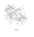
- Figure 8 shows two brackets 1 according to a third embodiment of the invention.
- the brackets 1 of Figure 8 are of a different shape to the brackets of Figures 3a and 3b or Figures 4a to 7b .
- Each bracket 1 of Figure 8 has a head portion 31 at one end of the bracket and an arm portion 32 extending from the head portion 11 to an end portion 33 at the other end of the bracket 1.
- the head portion 31 comprises a flat bonding face 2 for attaching to a stringer 3 of the fuel tank.
- the bonding face 2 has the form of a rounded rectangle.
- a rounded triangular-shaped arm 34 extends out from the bonding face 2.
- the rounded triangle is symmetrical and has its short side connected to a long edge of the rectangle of face 2.
- the two long sides of the triangle 34 form the outline of the arm portion 32.
- a right-angled triangle-shaped flange 35 Extending between the triangular arm 34 and the reverse of the bonding face 2 is a right-angled triangle-shaped flange 35.
- the shortest side of the triangle flange 35 is connected along the width across the middle of the reverse side of the bonding face 2.
- the middle-length side is connected along the middle of the length of the triangular arm 34.
- the hypotenuse of the flange 35 extends from one side of the reverse of the bonding face 2 to the apex of the triangular arm 34.
- the bracket At the far end of the arm portion, towards the apex of triangular arm 34, the bracket has a generally rectangular end portion 33.
- the end portion 33 is connected by one of the short sides of the rectangle 33 to the triangular arm 34, on the opposite side to the arm flange 35.
- the short side extends in the direction of the length of the triangular arm 34.
- a right-angled triangle-shaped flange 38 Extending between the opposite side of the triangular arm 34 to the flange 35 and the rectangular end portion 33 is a right-angled triangle-shaped flange 38.
- the shortest side of the triangle flange 38 is connected to the triangular arm 34.
- the middle-length side is connected to the arm potion 33, extending from its connection to the triangular arm 34 to a point about three quarters of the length along the end portion 33.
- the hypotenuse of the flange 38 extends from the triangular arm 34 to the rectangular end portion 33.
- the half-cylinder shaped nodule 30 allows a cable-tie to be used anywhere along the axis of the nodule.
- the half-cylinder shaped nodule is not suitable where cables need to be secured to the bracket in a different direction in relation to the bracket. I.e. the half-cylinder nodule only allows cables to be secured to a bracket in one direction. They cannot be used to secure cables to brackets in a choice of different transverse directions.
- the flat bonding faces 2 of the brackets 1 are attached to the surface of a stringer 3 or rib 9 of the fuel tank of an aircraft, using adhesive or screws or rivets.
- the cable 6 is placed adjacent the bracket, underneath the end portion 33.
- a cable-tie (not shown) is then looped around the cable 6, end portion 33 and nodule 30, and tightened to a set torque by a torque gun so as to secure the cable to the underside of the end portion 33.
- the nodule on the bracket need not be in contact with the cable-tie all the way round its periphery.
- the cable-tie could just be supported by the nodule on the middle of the nodule.
- the nodules could be thinner and taller.
- the bracket may additionally include one or more locating bumps to guide the cable into position on the bracket.
- the bumps may simply allow the cable to be placed between them. Alternatively, the cable may rest on an inner side or top surface of the bumps. In this configuration, the locating bumps form at least part of the cable abutment portion that the cable is abutted against.
- the brackets 1 may have a shorter arm portion 12, thereby giving a shorter bracket 1 with a length of 26mm.
- the bracket has been attached to the fuel tank by adhesive bonding.
- the bracket could be attached to the fuel tank by different means or a combination of means, for example by riveting, welding or using screws and bolts.
- the bracket does not have to be used on a composite, insulated structure and instead, for example, could be used in a metallic wing box made of aluminium alloy.
- the bracket does not have to be made from an insulating material, and could, for example, be made from a metallic material, such as aluminium alloy.
- the bracket could be made in a similar way to the nylon coated aluminium alloy brackets described in the prior art.
- the bracket could also be used for different applications.
- the bracket could be used in any application where it is desired that a cable be attached to a surface by brackets and cable-ties, where it is important that the cable is not allowed to become loose in the cable-tie and move in relation to the brackets.
- the brackets could be used to attach flight test cabling or to attach cable to a trailing edge of an aircraft wing.
Landscapes
- Engineering & Computer Science (AREA)
- Mechanical Engineering (AREA)
- Aviation & Aerospace Engineering (AREA)
- Architecture (AREA)
- Civil Engineering (AREA)
- Structural Engineering (AREA)
- Installation Of Indoor Wiring (AREA)
- Clamps And Clips (AREA)
Abstract
Description
- The present invention concerns brackets for attaching an electrical cable to a vehicle. More particularly, but not exclusively, this invention concerns a bracket for attaching to a fuel tank of an aircraft in order to secure an electrical cable. The invention also concerns an electrical assembly comprising a plurality of such brackets, a fuel tank comprising a plurality of such brackets, an aircraft comprising a plurality of such brackets or such an electrical assembly or fuel tank and a method of attaching a cable to a vehicle.
- Such brackets are often used to securely hold electrical cable, which is part of a Fuel Quantity Indication (FQI) System of an aircraft. The cable has to be held within the aircraft fuel tank, generally contained within the wing of an aircraft. To comply with the electrical installation requirements, any cable must be maintained at a minimum gap of 10mm from the fuel tank structure. The cable must have a greater clearance from other systems. It also must remain firmly in position with the minimum possible amount of sag between brackets for the life of the aircraft.
- In a metallic fuel tank (for example, made out of aluminium alloy), the brackets are nylon coated aluminium and are attached to stringers and ribs of the fuel tank by drilling and riveting. Two nylon cable-ties are then used at each point of contact along the stringers/ribs to prevent the cable moving.
- In a composite wing box, the brackets must be made from a fully insulating material and metal rivets cannot be used to attach the bracket to the fuel tank. Therefore, for composite wings, the brackets used are made from a composite, insulating material, such as PEI (Polyetherimide) or glass fibre re-enforced plastic. The brackets are attached to the fuel tank by adhesive bonding. The nylon cable-ties are tightened using a torque gun (not shown) set at an appropriate torque for the cable-tie being used.
- Such a bracket, with the cable and cable-tie in place, is shown in
Figures 1a and1b . Thebracket 1 has a flat bondingface 2 at one end for attaching to astringer 3 of the fuel tank. At the opposite end, the bracket has a generally flat and square shapedcable mounting face 4. On each corner of themounting face 4 is a locatingbump 8. These locatingbumps 8 provide abutment surfaces for thecable 6 to rest on or against, thereby ensuring the cable rests in a certain position on thebracket 1. On each side of the square face, is aslot 5 for a cable-tie. Thecable 6 is secured to thecable mounting face 4 by a cable-tie 7 looped around thecable 6 andcable mounting face 4 through two opposite cable-tie slots 5. -
Figure 2 shows part of a wing box layout, showing the position of the brackets andcable 6, in relation to thestringers 3 andribs 9 of the fuel tank. Thecable 6 is generally run along the length of thestringers 3 and is attached to the stringers at various points with asingle bracket 1. These points are approximately 150 to 200mm apart. The spacing of the points is decided based on maintaining a minimum clearance distance even in the event of a cable-tie/bracket failure, and the resulting "skipping rope" effect of the cable between the brackets either side of the failure being able to swing. When the cable crosses over/under astringer 3 or arib 9, twobrackets 1 are used, one either side of the stringer/rib. - However, as time passes, the cable becomes loose in the cable-tie and moves about in the bracket. This means the cable can swing in each bracket, decreasing the distance from the cable to the stringers/ribs of the fuel tank.
- The present invention seeks to mitigate the above-mentioned problems. Alternatively or additionally, the present invention seeks to provide an improved bracket.
- The present invention provides, according to a first aspect, a bracket for attaching an electrical cable to a vehicle, the bracket comprising a vehicle attachment portion for attaching the bracket to a vehicle attachment surface of the vehicle, and a cable securing portion for securing the cable to the bracket, the cable securing portion comprising a cable abutment portion against the front surface of which the cable can be secured by a cable-tie forming a closed loop around the cable and cable abutment portion, and a non-planar rear surface which at least partially defines the path of the closed loop of the cable-tie behind the cable abutment portion, the path passing a first region on one side of the non-planar rear surface and a second region on the opposite side of the non-planar rear surface, wherein, in use, the non-planar rear surface directly supports the cable-tie at a third region along the path of the closed loop, the third region being positioned, along the path, between the first and second regions.
- The applicant has realised that with the prior art brackets, a gap is formed between the cable-tie and the reverse side of the cable abutment portion. Even if a greater torque is applied to tighten the cable-tie, the gap still remains. The gap exists because the cable-tie tends to adopt a degree of curvature around right -angled corners, such that the cable-tie lifts off the reverse side of the cable abutment portion. The gap imparts a slack into the loop of the cable-tie, which over time is distributed around the loop, allowing the cable to move with respect to the bracket.
- In addition, the aviation fuel in the fuel tank acts as a lubricant and the over braid coating on the outside of the cable is made from a PEEK™ material, which has a low coefficient of friction. Hence, the cable can become loose very easily.
- Providing a non-planar rear surface on the cable securing portion acts to fill the gap, meaning that the cable-tie has less slack in its loop. This allows the cable to be more firmly secured to the bracket by a cable-tie and reduces the relative movement between the bracket and the cable and prevents the cable from moving out of position.
- In addition, with a prior art bracket, in the event of a cable-tie/bracket failure, the length of cable between the brackets either side of the failure is increased. This is due to the cable being loose in the bracket. This further adds to the undesirable "skipping rope" effect. This is unlikely to happen in the bracket of the present invention as the cable is much less able to move in the bracket and so the length of cable between the brackets either side of the failure is not increased. Hence, the "skipping rope" effect is limited to the effect produced by the amount of length between the brackets on installation. This increases the possible distance between the brackets and means less brackets have to be installed. This obviously saves time, money and weight.
- Preferably, the third region is positioned, along the path, midway between the first and second regions.
- Preferably, the non-planar rear surface defines at least three points of contact for the cable-tie on the path behind the cable abutment portion, including (i) a first point of contact at the first region, (ii) a second point of contact at the second region, and (iii) a third point of contact at the third region, wherein the distance of the third point from the cable abutment portion is both greater than the distance of the first point and greater than the distance of the second point from the cable abutment portion. This provides a path for the cable-tie that provides for curvature of the cable-tie.
- Preferably, the path provided has a radius of curvature that does not exceed the natural minimum radius of curvature of the cable-tie. The applicant has realised that, in the prior art brackets, the areas of high curvature of the cable-tie at the edges of the rear of the cable mounting face can cause the cable-tie to stretch over time. This reduces the tension on the cable-tie and increases slack in the cable-tie loop. The natural minimum radius of curvature of the cable-tie can therefore be defined as the smallest radius of curvature of the cable-tie at which deformation of the cable-tie does not occur.
- Preferably, the cable-tie to be used with the bracket has a width of between 1mm and 5mm, preferably between 2mm and 4mm, most preferably approximately 3mm. Preferably, the cable-tie to be used with the bracket has a depth of between 0 and 5mm, preferably between 1 and 2mm, most preferably approximately 1.5mm. Preferably, the cable-tie to be used with the bracket has a length of between 200 and 300mm most preferably approximately 250mm. The closed loop formed by the cable-tie preferably has a perimeter of between 3 and 15 mm, preferably between 50 and 100mm.
- Preferably, at least part of the non-planar rear surface has the shape of a cylinder which presents a curved convex profile, thereby defining a substantially curved path in one direction behind the cable abutment portion.
- Preferably, the non-planar rear surface defines said at least three points of contact for the cable-tie on the path behind the cable abutment portion in more than one direction behind the cable abutment portion, thereby allowing the cable to be secured to the bracket in a plurality of directions with respect to the vehicle.
- Preferably, the non-planar rear surface defines said at least three points of contact for the cable-tie on the path behind the cable abutment portion in more two transverse directions behind the cable abutment portion, thereby allowing the cable to be secured to the bracket in two directions transverse to each other.
- Preferably, at least part of the non-planar rear surface has a profile substantially in the form of a dome.
- Preferably, the dome is a substantially hemispherical dome.
- Preferably, the vehicle attachment portion and the front of the cable abutment portion are offset from each other so that, in use, the bracket can extend over a step on a bracket attachment portion of the vehicle. Preferably, the offset is between 2mm and 10mm, preferably between 4 and 8mm, most preferably approximately 6mm.
- Preferably, no part of the vehicle attachment portion is in line with the front of the cable abutment portion in a direction extending away from the surface of the vehicle attachment portion. In other words, the whole of the vehicle attachment portion is out of line of the front of the cable abutment portion, in a direction extending away from the surface of the vehicle attachment portion. This means that, in use, the cable can be secured to the front of the cable abutment portion in line with a part of the vehicle that cannot be used for attaching the bracket. For example, the vehicle attachment portion of the bracket can be attached to a smooth part of the vehicle surface, whereas the cable can be attached to the front of the cable abutment portion in line with a non-smooth part of the vehicle surface.
- Preferably, a vehicle attachment surface of the vehicle attachment portion and the cable abutment portion are substantially perpendicular to each other. This allows the cable to be run offset from a bracket attachment point on the vehicle.
- Preferably, the bracket also comprises an arm portion connecting the vehicle attachment portion and cable securing portion, the arm portion having a length such that the cable can be attached at a clearance distance from a bracket attachment surface of the vehicle.
- Preferably, the bracket also comprises one or more guiding elements on or adjacent the cable abutment portion for guiding the cable into position on the cable abutment portion. Preferably, the guiding element(s) are in the form of locating bumps extending outwards on the front of the cable abutment portion.
- Preferably, the bracket is wholly made from an electrically insulating material. Preferably, the material is PEI (Polyetherimide) or glass fibre re-enforce plastic.
- Preferably, the brackets are approximately 1 to 2 inches (25 to 50mm) long. Preferably, the path of the cable-tie over the non-planar rear surface has a radius of 7 to 10mm, but preferably, could be as large as 20mm. Preferably, the cable radius is 1 to 20mm or larger. Preferably, the non-planar rear surface is designed to provide a curvature on the cable-tie substantially the same as the cable radius.
- Preferably the bracket is for use on an aircraft. Preferably, the bracket is for attaching to a fuel tank of the vehicle. Most preferably, the bracket is for use in attaching an electrical cable of a Fuel Quantity Indication (FQI) System to an inside of an aircraft fuel tank. Preferably, the bracket is for use in a composite wing box and is designed to be attached to the aircraft by bonding.
- The invention also provides an electrical assembly comprising a plurality of brackets as described above and a cable secured to each of the brackets by a cable-tie.
- The invention also provides a stringer or rib with a plurality of brackets as described above, or an electrical assembly as described above mounted thereon.
- The invention also provides a fuel tank comprising a plurality of brackets as described above or an electrical assembly as described above or a stringer or rib as described above.
- The invention also provides an aircraft comprising a plurality of brackets as described above or an electrical assembly as described above or a stringer or rib as described above or a fuel tank as described above.
- According to a second aspect of the invention there is also provided a method of attaching a cable to a vehicle comprising the following steps providing a bracket as described above, attaching the vehicle attachment portion of the bracket to the vehicle, placing the cable on or near the front of the cable abutment portion of the bracket, and tightening a cable-tie around the cable and cable abutment portion so as to secure the cable against the cable abutment portion of the bracket.
- Preferably, when the cable-tie is tightened, the cable-tie forms a closed loop and is held in direct contact against the third region of the non-planar rear surface.
- It will of course be appreciated that features described in relation to one aspect of the present invention may be incorporated into other aspects of the present invention. For example, the method of the invention may incorporate any of the features described with reference to the apparatus of the invention and vice versa.
- Embodiments of the present invention will now be described by way of example only with reference to the accompanying schematic drawings of which:
- Figure 1a
- shows a top view of a prior art bracket, attached to a stringer, with a cable and cable-tie;
- Figure 1b
- shows a side view of the stringer, bracket, cable and cable-tie of
Figure 1a ; - Figure 2
- shows a plan view of a typical routing of FQI cables inside a wing box;
- Figure 3a
- shows a side view of a bracket according to a first embodiment of the invention, attached to the inside of a stringer, with a cable and cable-tie;
- Figure 3b
- shows a front view of the stringer, bracket, cable and cable-tie of
Figure 3a ; - Figure 4a
- shows an isometric view of a bracket according to a second embodiment of the invention;
- Figure 4b
- shows a front view of the bracket of
Figure 4a ; - Figure 4c
- shows a side view of the bracket of
Figure 4a ; - Figure 4d
- shows a top view of the bracket of
Figure 4a ; - Figure 5a
- shows a side view of the bracket of
Figure 4a , attached to a stringer, with a cable and cable-tie; - Figure 5b
- shows a front view of the stringer, bracket, able and cable-tie of
Figure 5a ; - Figure 6
- shows a side view of two brackets of
Figure 4a , attached either side of a stringer, with a cable and cable-ties; - Figure 7a
- shows a side view of two brackets of
Figure 4a , attached either side of a rib, with a cable and cable-ties; - Figure 7b
- shows a front view of the rib, two brackets, cable and cable-ties of
Figure 7a ; and - Figure 8
- shows an isometric view of two brackets according to a third embodiment of the invention, attached either side of a rib, with a cable and a grommet, with the cable-ties omitted for clarity.
-
Figures 3a and3b show abracket 1 according to a first embodiment of the invention. It is similar to the prior art bracket ofFigures 1a and1b . Thebracket 1 has aflat bonding face 2 at one end for attaching to astringer 3 of the fuel tank. At the opposite end, the bracket has a generally square shapedcable mounting face 4. On each corner of the mountingface 4 is a locatingbump 8. These locating bumps 8 provide abutment surfaces for thecable 6 to rest on or against, thereby ensuring the cable rests in a certain position on thebracket 1. On each side of the square face is aslot 5 for a cable-tie. Thecable 6 is secured to thecable mounting face 4 by a cable-tie 7 looped around thecable 6 andcable mounting face 4 through two opposite cable-tie slots 5. - However, an important difference between the bracket of
Figures 3a and3b and the bracket ofFigures 1a and1b is that the bracket ofFigures 3a and3b also comprises anodule 10 on the back of thecable mounting face 4. The nodule is in the shape of a dome sat on a thin flat substantially circular disc. The dome of thenodule 10 has a radius of curvature of 14mm and the disc has a radius to match the base radius of the dome. Effectively, this means the nodule has straight sides near its base but a domed top. - When the
cable 6 is secured to thecable mounting face 4, the cable-tie 7 is looped around thecable 6,cable mounting face 4 andnodule 10 and then tightened. Hence, the cable-tie 7 forms a loop around thecable 6 andnodule 10. The loop formed is smooth with a relatively large radius of curvature (i.e. not tightly curved) for the entire loop. The bracket ofFigures 3a and3b is used to attach acable 6 along the inside of astringer 3. The cable-tie 7 has a width of 3mm, a depth of 1mm and an original length of 200 to 300mm. The closed loop formed by the cable-tie has a perimeter of 80mm. The cable-tie loop is formed in the normal manner. The excess cable-tie length not forming part of the closed loop can be cut off. -
Figures 4a to 4d show abracket 1 according to a second embodiment of the invention. Thebracket 1 is of a different shape to the bracket ofFigures 3a and3b . - The
bracket 1 has ahead portion 11 at one end of the bracket and anarm portion 12 extending from thehead portion 11 to anend portion 13 at the other end of thebracket 1. - The
head portion 11 comprises aflat bonding face 2 for attaching to astringer 3 of the fuel tank using adhesive. Thebonding face 2 has a thickness of 2mm and is in the form of a round-cornered rectangle. The dimensions of the rectangle are 20 by 30mm. On the other side of theface 2, on the short edges of the rectangle of thehead portion 11, two slopingwalls 14 extend upwards. Thewalls 14 have a thickness of 2mm. Thewalls 14 are sloped such that their height from theface 2 increases as they move away from the head portion end of thebracket 1. - At the end of the rectangle of the mounting
face 2 nearest thearm portion 12, the slopingwalls 14 curve round the corners of the rectangle and then continue extending away from thehead portion 11 end of thebracket 1, to form aneck portion 18 at the other end of thehead portion 11. This creates a hollow-shaped "scoop" 15 on thehead portion 11. - Also at this end of the rectangular mounting
face 2, anindent step 16 is formed so as to effectively raise the height of theface 2. This steppedface 17 continues away from thehead portion 11 and effectively shortens the height of thesloping walls 14. Theface 17 and slopingwalls 14 extend away from thehead portion 11 to form anarm portion 12. Thearm potion 12 is in the form of a channel. - At the far end of the arm portion, the bracket has a generally square shaped
cable mounting face 4 facing outwards, away from thebracket 1, to effectively close off the channel of thearm portion 12. Thecable mounting face 4 has a thickness of 2mm and is at 90 degrees to the angle of theflat bonding face 2. The cable mounting face is an 18mm by 18mm square shape. - At the middle of each side of the
square face 4, is aslot 5 for a cable-tie. On the three sides of theface 4 adjacent the steppedface 17 or the two slopingwalls 14, the slot also extends slightly down thearm portion 12 on theface 17 andwalls 14 so as to form corner cut-outs. The slots extend 7mm in length down eachwall 14 andface 17 and extend 4mm into each side of thecable mounting face 4. Theslots 5 each have a width of 5.2mm. - In between the slots, on the rear side of the
cable mounting face 4, is anodule 10. Thenodule 10 is similar to thenodule 10 ofFigures 3a and3b . - The
bracket 1 has an overall length of 52mm. - As can be seen in
Figures 5a and5b , when thecable 6 is secured to thecable mounting face 4, the cable-tie 7 is looped around thecable 6,cable mounting face 4 andnodule 10 through two opposite cable-tie slots 5 and then tightened. Hence, the cable-tie 7 forms a loop around thecable 6 andnodule 10. The loop formed is smooth with a relatively low radius of curvature for the entire loop. In the embodiment shown inFigures 5a and5b , thecable 6 is run parallel along the underneath of thestringer 3. The axis of thecable 6 is parallel to the stringer length and thecable 6 extends across thecable mounting face 4 from one side of the bracket to the other, i.e. parallel to the long sides of therectangular face 2. - Alternatively, the
cable 6 can be run under, substantially perpendicular to thestringer 3. Such a configuration is shown inFigure 6 . Onebracket 1 is mounted on the left hand side of the stringer with theflat bonding face 2 facing right and asecond bracket 1 is mounted on the right hand side of the stringer with theflat bonding face 2 facing left. Hence, the two flat bonding faces 2 face each other. Thebrackets 1 are orientated so theend portions 13 of thebrackets 1 are lowermost and hang down below thestringer 3. - The
cable 6 is mounted to the cable mounting faces 4 of eachbracket 1 so as to run underneath thestringer 3. Twobrackets 1 are used so that, in the event of one of them failing, thecable 6 is still kept the required distance away from thestringer 3. Here, the axis of thecable 6 crosses under thestringer 3 and thecable 6 extends across the cable mounting faces 4 from the tops to the bottoms of the twobrackets 1, i.e. perpendicular to the plane of therectangular face 2. - Hence, the cable axis of
Figures 5a and5b is perpendicular to the cable axis ofFigure 6 . Thebrackets 1 have four cable-tie slots 5 to allow either axis to be chosen. - Alternatively, as shown in
Figures 7a and7b , thecable 6 can be run through ahole 9a in arib 9. Onebracket 1 is mounted on the left hand side of therib 9, below thehole 9a with theflat bonding face 2 facing right and asecond bracket 1 is mounted on the right hand side of the rib, below thehole 9a with theflat bonding face 2 facing left. Hence, the two flat bonding faces 2 face each other. Thebrackets 1 are orientated so theend portions 13 of thebrackets 1 are uppermost, either side of thehole 9a. - The
cable 6 is mounted to the cable mounting faces 4 of eachbracket 1 so as to run through thehole 9a. Twobrackets 1 are used so that, in the event of one of them failing, thecable 6 is still kept the required distance away from therib 9. Here, the axis of thecable 6 crosses through therib 9 and thecable 6 extends across the cable mounting faces 4 from the tops to the bottoms of the twobrackets 1, i.e. perpendicular to the plane of therectangular face 2. - Hence, the cable axis of
Figures 7a and7b , in relation to the brackets, is the same as the cable axis ofFigure 6 . - The
rib 9 has a raised portion, in the form of anannular boss 9b surrounding thehole 9a. It can be seen inFigure 7a that theindent step 16, and the fact thatface 17 is raised in relation toface 2, allows thearm portion 12 of thebracket 1 to pass over theannular boss 9b of therib 9. - In use, the flat bonding faces 2 of the
brackets 1 are attached to the surface of astringer 3 orrib 9 of the fuel tank of an aircraft, using adhesive. Once all therelevant brackets 1 are attached, thecable 6 is placed adjacent eachbracket 1. A cable-tie 7 is then looped around thecable 6,cable mounting face 4 andnodule 10, and tightened to a set torque by a torque gun. -
Figure 8 shows twobrackets 1 according to a third embodiment of the invention. Thebrackets 1 ofFigure 8 are of a different shape to the brackets ofFigures 3a and3b orFigures 4a to 7b . - Each
bracket 1 ofFigure 8 has ahead portion 31 at one end of the bracket and anarm portion 32 extending from thehead portion 11 to anend portion 33 at the other end of thebracket 1. - The
head portion 31 comprises aflat bonding face 2 for attaching to astringer 3 of the fuel tank. Thebonding face 2 has the form of a rounded rectangle. On the other side of theface 2, a rounded triangular-shapedarm 34 extends out from thebonding face 2. The rounded triangle is symmetrical and has its short side connected to a long edge of the rectangle offace 2. The two long sides of thetriangle 34 form the outline of thearm portion 32. - Extending between the
triangular arm 34 and the reverse of thebonding face 2 is a right-angled triangle-shapedflange 35. The shortest side of thetriangle flange 35 is connected along the width across the middle of the reverse side of thebonding face 2. The middle-length side is connected along the middle of the length of thetriangular arm 34. The hypotenuse of theflange 35 extends from one side of the reverse of thebonding face 2 to the apex of thetriangular arm 34. - At the far end of the arm portion, towards the apex of
triangular arm 34, the bracket has a generallyrectangular end portion 33. Theend portion 33 is connected by one of the short sides of therectangle 33 to thetriangular arm 34, on the opposite side to thearm flange 35. The short side extends in the direction of the length of thetriangular arm 34. - Extending between the opposite side of the
triangular arm 34 to theflange 35 and therectangular end portion 33 is a right-angled triangle-shapedflange 38. The shortest side of thetriangle flange 38 is connected to thetriangular arm 34. The middle-length side is connected to thearm potion 33, extending from its connection to thetriangular arm 34 to a point about three quarters of the length along theend portion 33. The hypotenuse of theflange 38 extends from thetriangular arm 34 to therectangular end portion 33. - Adjacent the end of the triangular
end portion flange 38, is a cable-tie slot 5 extending partly across the width of theend portion 33. Adjacent theslot 5, on the upper surface of theend portion 33 is a half-cylinder shapednodule 30. The half-cylinder shapednodule 30 allows a cable-tie to be used anywhere along the axis of the nodule. However, the half-cylinder shaped nodule is not suitable where cables need to be secured to the bracket in a different direction in relation to the bracket. I.e. the half-cylinder nodule only allows cables to be secured to a bracket in one direction. They cannot be used to secure cables to brackets in a choice of different transverse directions. - In use, the flat bonding faces 2 of the
brackets 1 are attached to the surface of astringer 3 orrib 9 of the fuel tank of an aircraft, using adhesive or screws or rivets. Once all therelevant brackets 1 are attached, thecable 6 is placed adjacent the bracket, underneath theend portion 33. A cable-tie (not shown) is then looped around thecable 6,end portion 33 andnodule 30, and tightened to a set torque by a torque gun so as to secure the cable to the underside of theend portion 33. - Whilst the present invention has been described and illustrated with reference to particular embodiments, it will be appreciated by those of ordinary skill in the art that the invention lends itself to many different variations not specifically illustrated herein. By way of example only, certain possible variations will now be described.
- The nodule on the bracket need not be in contact with the cable-tie all the way round its periphery. For example, the cable-tie could just be supported by the nodule on the middle of the nodule. The nodules could be thinner and taller.
- The bracket may additionally include one or more locating bumps to guide the cable into position on the bracket. The bumps may simply allow the cable to be placed between them. Alternatively, the cable may rest on an inner side or top surface of the bumps. In this configuration, the locating bumps form at least part of the cable abutment portion that the cable is abutted against. There may be two locating bumps located towards two adjacent corners of the cable mounting face. This would provide a guide for a cable resting on the bracket in one orientation. There may be four locating bumps located towards each of the four corners off the cable mounting face. This would provide a guide for a cable in two perpendicular orientations on the bracket.
- The
brackets 1 may have ashorter arm portion 12, thereby giving ashorter bracket 1 with a length of 26mm. - In the above examples, the bracket has been attached to the fuel tank by adhesive bonding. However, the bracket could be attached to the fuel tank by different means or a combination of means, for example by riveting, welding or using screws and bolts. For example, there are two
holes 37 through thebonding face 2 for attaching thebracket 1 to the fuel tank inFigure 8 . - Of course, it is also possible to attach only one or some of the brackets to the fuel tank before starting to secure the cable to the brackets on the fuel tank. Alternatively, the cable could be secured to the brackets before the brackets are attached to the fuel tank.
- The bracket does not have to be used on a composite, insulated structure and instead, for example, could be used in a metallic wing box made of aluminium alloy.
- The bracket does not have to be made from an insulating material, and could, for example, be made from a metallic material, such as aluminium alloy. The bracket could be made in a similar way to the nylon coated aluminium alloy brackets described in the prior art.
- The bracket could also be used for different applications. In fact, the bracket could be used in any application where it is desired that a cable be attached to a surface by brackets and cable-ties, where it is important that the cable is not allowed to become loose in the cable-tie and move in relation to the brackets. For example, the brackets could be used to attach flight test cabling or to attach cable to a trailing edge of an aircraft wing.
- Where in the foregoing description, integers or elements are mentioned which have known, obvious or foreseeable equivalents, then such equivalents are herein incorporated as if individually set forth. Reference should be made to the claims for determining the true scope of the present invention, which should be construed so as to encompass any such equivalents. It will also be appreciated by the reader that integers or features of the invention that are described as preferable, advantageous, convenient or the like are optional and do not limit the scope of the independent claims. Moreover, it is to be understood that such optional integers or features, whilst of possible benefit in some embodiments of the invention, may not be desirable, and may therefore be absent, in other embodiments.
Claims (16)
- A bracket for attaching an electrical cable to a vehicle, the bracket comprising;i) a vehicle attachment portion for attaching the bracket to a vehicle attachment surface of the vehicle, andii) a cable securing portion for securing the cable to the bracket, the cable securing portion comprising;- a cable abutment portion against the front surface of which the cable can be secured by a cable-tie forming a closed loop around the cable and cable abutment portion, and- a non-planar rear surface which at least partially defines the path of the closed loop of the cable-tie behind the cable abutment portion, the path passing a first region on one side of the non-planar rear surface and a second region on the opposite side of the non-planar rear surface, wherein, in use, the non-planar rear surface directly supports the cable-tie at a third region along the path of the closed loop, the third region being positioned, along the path, between the first and second regions.
- A bracket as claimed in claim 1, wherein the non-planar rear surface defines at least three points of contact for the cable-tie on the path behind the cable abutment portion, including (i) a first point of contact at the first region, (ii) a second point of contact at the second region, and (iii) a third point of contact at the third region, wherein the distance of the third point from the cable abutment portion is both greater than the distance of the first point and greater than the distance of the second point from the cable abutment portion.
- A bracket as claimed in claim 2, wherein at least part of the non-planar rear surface has the shape of a cylinder which presents a curved convex profile, thereby defining a substantially curved path in one direction behind the cable abutment portion.
- A bracket as claimed in claim 2, wherein the non-planar rear surface defines said at least three points of contact for the cable-tie on the path behind the cable abutment portion in more than one direction behind the cable abutment portion, thereby allowing the cable to be secured to the bracket in a plurality of directions with respect to the vehicle.
- A bracket as claimed in claim 4, wherein at least part of the non-planar rear surface has a profile substantially in the form of a dome.
- A bracket as claimed in claim 5, wherein the dome is a substantially hemispherical dome.
- A bracket as claimed in any preceding claim, wherein the vehicle attachment portion and the front of the cable abutment portion are offset from each other so that, in use, the bracket can extend over a step on a bracket attachment surface of the vehicle.
- A bracket as claimed in any preceding claim, wherein the vehicle is an aircraft.
- A bracket as claimed in any preceding claim, wherein the bracket is for attaching to a fuel tank of the vehicle.
- A bracket as claimed in any preceding claim, wherein the bracket is wholly made from an electrically insulating material.
- An electrical assembly comprising a plurality of brackets according to any preceding claim and a cable secured to each of the brackets by a cable-tie.
- A stringer or rib with:- a plurality of brackets according to any of claims 1 to 10, or- an electrical assembly according to claim 11,mounted thereon.
- A fuel tank comprising a plurality of brackets according to any of claims 1 to 10 or an electrical assembly according to claim 11 or a stringer or rib according to claim 12.
- An aircraft comprising a plurality of brackets according to any of claims 1 to 10 or an electrical assembly according to claim 11 or a stringer or rib according to claim 12 or a fuel tank according to claim 13.
- A method of attaching a cable to a vehicle comprising the following steps;i) providing a bracket according to any of claims 1 to 10,ii) attaching the vehicle attachment portion of the bracket to the vehicle,iii) placing the cable on or near the front of the cable abutment portion of the bracket, andiv) tightening a cable-tie around the cable and cable abutment portion so as to secure the cable against the cable abutment portion of the bracket.
- A method according to claim 15, wherein, when the cable-tie is tightened, the cable-tie forms a closed loop and is held in direct contact against the third region of the non-planar rear surface.
Applications Claiming Priority (1)
| Application Number | Priority Date | Filing Date | Title |
|---|---|---|---|
| GBGB1001002.3A GB201001002D0 (en) | 2010-01-22 | 2010-01-22 | A bracket for attaching an electrical cable to a vehicle |
Publications (2)
| Publication Number | Publication Date |
|---|---|
| EP2347954A1 true EP2347954A1 (en) | 2011-07-27 |
| EP2347954B1 EP2347954B1 (en) | 2012-10-31 |
Family
ID=42045886
Family Applications (1)
| Application Number | Title | Priority Date | Filing Date |
|---|---|---|---|
| EP11151595A Not-in-force EP2347954B1 (en) | 2010-01-22 | 2011-01-20 | A bracket for attaching an electrical cable to a vehicle |
Country Status (3)
| Country | Link |
|---|---|
| US (1) | US9509129B2 (en) |
| EP (1) | EP2347954B1 (en) |
| GB (1) | GB201001002D0 (en) |
Cited By (1)
| Publication number | Priority date | Publication date | Assignee | Title |
|---|---|---|---|---|
| US8791362B2 (en) | 2012-05-24 | 2014-07-29 | General Electric Company | Shutter door assembly for an electrical panel |
Families Citing this family (5)
| Publication number | Priority date | Publication date | Assignee | Title |
|---|---|---|---|---|
| US9341206B2 (en) | 2013-03-15 | 2016-05-17 | Panduit Corp. | Flange for support channel assembly |
| US10050422B2 (en) | 2014-10-15 | 2018-08-14 | Lear Corporation | Wiring carrier |
| EP3015317B1 (en) * | 2014-10-30 | 2018-12-05 | Nexans | Assembly for the attachment of an elongated object in a motor vehicle |
| GB2554073B (en) * | 2016-09-14 | 2019-10-02 | Pandrol Vortok Ltd | Cable management assembly |
| US10690267B2 (en) | 2018-07-16 | 2020-06-23 | Raytheon Technologies Corporation | Adjustable holding assembly |
Citations (3)
| Publication number | Priority date | Publication date | Assignee | Title |
|---|---|---|---|---|
| US5823484A (en) * | 1996-09-30 | 1998-10-20 | Mcdonnell Douglas Corporation | Hose pipe, or conduit snap-in support system |
| US20050082431A1 (en) * | 2003-10-21 | 2005-04-21 | Scown Stephen L. | Aircraft frame hole patterns and brackets, and associated methods |
| DE102006053966A1 (en) * | 2006-11-16 | 2008-05-21 | Airbus Deutschland Gmbh | Universal line holder for aircraft, has function module fastened to base module, which has attachment surface with hole and locking surface, and bolt attached for fixing holder in borehole in reinforcement structure |
Family Cites Families (38)
| Publication number | Priority date | Publication date | Assignee | Title |
|---|---|---|---|---|
| US3250505A (en) * | 1965-09-28 | 1966-05-10 | Gen Electric | Tie block |
| US3486725A (en) * | 1968-05-17 | 1969-12-30 | Thomas & Betts Corp | Article lashing support |
| US3632071A (en) * | 1969-11-24 | 1972-01-04 | Panduit Tinley Park | Mount for receiving and retaining a strap |
| US3913876A (en) * | 1972-08-24 | 1975-10-21 | Panduit Corp | Cable tie support |
| US3933377A (en) * | 1974-05-30 | 1976-01-20 | Mckenney's, Inc. | Hanger assembly for pipe |
| US4369944A (en) * | 1980-07-30 | 1983-01-25 | Western Electric Company, Inc. | Universal strand clamp and strand clamp assembly |
| FR2496349A1 (en) | 1980-12-15 | 1982-06-18 | Aerospatiale | DEVICE FOR SUPPORTING EXTENDED OBJECTS SUCH AS CABLES, CABLE BEAMS OR THE LIKE AND INSTALLATIONS COMPRISING SUCH DEVICES |
| US4395009A (en) * | 1981-05-28 | 1983-07-26 | The Boeing Company | Raceway clamp |
| US4462141A (en) * | 1981-07-17 | 1984-07-31 | Virginia Plastics Company | Flexible locking clamp used with tubular guard for linear body |
| US4562982A (en) * | 1984-02-15 | 1986-01-07 | Panduit Corp. | Stackable cable spacer |
| US4638966A (en) * | 1985-06-21 | 1987-01-27 | Robroy Industries | Support member for hanging cable |
| US4768741A (en) * | 1987-04-30 | 1988-09-06 | Logsdon Duane D | Pipe hangers |
| US4874908A (en) * | 1987-07-08 | 1989-10-17 | Minnesota Mining And Manufacturing Company | Wiring harness |
| US4925136A (en) * | 1987-09-22 | 1990-05-15 | Frank George Grundman | Pipe support apparatus and/or methods of supporting pipes |
| US5042114A (en) * | 1991-01-04 | 1991-08-27 | Parrish Charles E | Adjustable clamp with handle |
| US5730399A (en) * | 1996-02-21 | 1998-03-24 | Volvo Gm Heavy Truck Corporation | Method and assembly for mounting service lines |
| US6129317A (en) * | 1996-05-20 | 2000-10-10 | Thomas & Betts International, Inc. | Support spacer for aerial cable |
| USD401498S (en) * | 1997-11-20 | 1998-11-24 | Panduit Corp. | Ribless mount |
| US6190083B1 (en) * | 1998-02-23 | 2001-02-20 | Winton, Iii George R. | Self-clinching cable tie mount |
| US5941483A (en) * | 1998-04-24 | 1999-08-24 | Volvo Trucks North America, Inc. | Service line clamp with cable tie mount |
| US6196751B1 (en) * | 1998-09-11 | 2001-03-06 | Thomas & Betts International, Inc. | Stud mounted fastener for routing wire |
| DE10010933C1 (en) * | 2000-03-06 | 2001-08-16 | Daimler Chrysler Ag | Cable holder for fastening cables in vehicle structures has a fastening clip with a hole for fastening it with connector elements to a vehicle structure and a dish-shaped bulge to put the cable on forming one piece with the fastening clip. |
| US6367745B1 (en) * | 2000-07-17 | 2002-04-09 | George R. Winton, III | Self-clinching cable tie mount |
| US6533226B2 (en) * | 2000-09-14 | 2003-03-18 | Hellermanntyton Corporation | Saddle mount |
| US6669151B2 (en) * | 2001-02-08 | 2003-12-30 | Honda Giken Kogyo Kabushiki Kaisha | Cable tie mounting base |
| DE10129841A1 (en) * | 2001-06-21 | 2003-01-02 | Emhart Llc Newark | Retaining clip for attaching at least one line to a carrier |
| US7083152B2 (en) * | 2002-11-07 | 2006-08-01 | Computer Network Technology Corporation | Method and apparatus for restraining a data cable |
| DE10349046A1 (en) * | 2003-10-17 | 2005-06-02 | Newfrey Llc, Newark | Holder for elongated objects, in particular cables |
| US7134633B2 (en) * | 2004-02-05 | 2006-11-14 | Medcount Systems, L.L.C. | Method and apparatus for securing cables and the like |
| US8028962B2 (en) * | 2004-04-30 | 2011-10-04 | Hellermanntyton Corporation | Fir tree mount for cable ties |
| JP4423101B2 (en) | 2004-05-11 | 2010-03-03 | 矢崎総業株式会社 | Wire plate fixing plate, wire harness protection protector and fixing clip |
| US20060051181A1 (en) * | 2004-09-08 | 2006-03-09 | Winton George R Iii | Universal clinch base |
| DE102004049894A1 (en) | 2004-10-13 | 2006-05-18 | Airbus Deutschland Gmbh | Retention device for cables e.g. for aircraft construction, includes stiffening ribs along length of component |
| DE102006033800A1 (en) | 2006-07-19 | 2008-01-31 | Siemens Ag | Cable fastening device, has pair of opposite recesses provided in front side open cable groove for making cable connector to fasten cable that is inserted in groove, where groove has extension in axial direction over base |
| USD571643S1 (en) * | 2007-02-12 | 2008-06-24 | Trelleborg Industrial Avs Ltd. | Vibration and shock absorber |
| JP2008296916A (en) | 2007-05-29 | 2008-12-11 | Sumitomo Wiring Syst Ltd | Wire harness fixing tool, wire harness apparatus with fixing tool and method for manufacturing wiring harness apparatus with fixing tool |
| US8141826B1 (en) * | 2008-01-15 | 2012-03-27 | Securus, Inc. | Pipe holding bracket |
| US7861981B2 (en) * | 2008-10-22 | 2011-01-04 | Pratt & Whitney Canada Corp. | Protective saddle mount for cable tie |
-
2010
- 2010-01-22 GB GBGB1001002.3A patent/GB201001002D0/en not_active Ceased
-
2011
- 2011-01-20 EP EP11151595A patent/EP2347954B1/en not_active Not-in-force
- 2011-01-24 US US12/929,424 patent/US9509129B2/en not_active Expired - Fee Related
Patent Citations (3)
| Publication number | Priority date | Publication date | Assignee | Title |
|---|---|---|---|---|
| US5823484A (en) * | 1996-09-30 | 1998-10-20 | Mcdonnell Douglas Corporation | Hose pipe, or conduit snap-in support system |
| US20050082431A1 (en) * | 2003-10-21 | 2005-04-21 | Scown Stephen L. | Aircraft frame hole patterns and brackets, and associated methods |
| DE102006053966A1 (en) * | 2006-11-16 | 2008-05-21 | Airbus Deutschland Gmbh | Universal line holder for aircraft, has function module fastened to base module, which has attachment surface with hole and locking surface, and bolt attached for fixing holder in borehole in reinforcement structure |
Cited By (1)
| Publication number | Priority date | Publication date | Assignee | Title |
|---|---|---|---|---|
| US8791362B2 (en) | 2012-05-24 | 2014-07-29 | General Electric Company | Shutter door assembly for an electrical panel |
Also Published As
| Publication number | Publication date |
|---|---|
| GB201001002D0 (en) | 2010-03-10 |
| US9509129B2 (en) | 2016-11-29 |
| EP2347954B1 (en) | 2012-10-31 |
| US20110180320A1 (en) | 2011-07-28 |
Similar Documents
| Publication | Publication Date | Title |
|---|---|---|
| EP2347954B1 (en) | A bracket for attaching an electrical cable to a vehicle | |
| US7721992B2 (en) | Aircraft floor to fuselage attachment | |
| US11305849B2 (en) | Float, float assembly, and method for installing float assembly | |
| US9601908B2 (en) | Wire support member for an environmental control system | |
| US20110303456A1 (en) | Modular conduit retention system | |
| US8157235B2 (en) | Device for fixing a wire cable raceway to a threaded rod | |
| US20100238642A1 (en) | Support to fix electrical cables on a structure | |
| EP3398250B1 (en) | Solar cell assembly and solar cell module | |
| US11087941B2 (en) | Electrical junction box | |
| US6743976B2 (en) | Conduit channel for insulated conductor lines and devices of an in-flight entertainment system in an aircraft | |
| US9293899B2 (en) | Transition splice for cable routing system | |
| JP7205243B2 (en) | Conductive track with bracket | |
| US7600723B2 (en) | Protection hose arrangement for conductors installed in an aircraft | |
| US9791096B2 (en) | Anti-rotation bracket | |
| US11437952B2 (en) | Composition roof accessory mount | |
| US20030042036A1 (en) | Aircraft junction box | |
| US5823484A (en) | Hose pipe, or conduit snap-in support system | |
| US20220029397A1 (en) | Slider bracket assembly | |
| EP3695458B1 (en) | Adjustable antenna mounting system | |
| US12424832B2 (en) | Aircraft cable tray with piston | |
| US9502870B2 (en) | Wire support member for an environmental control system | |
| KR20200106781A (en) | Liquid dome and floating structure including the same | |
| US10562603B2 (en) | Aircraft insulation component having recesses for receiving framework structures | |
| US20240051667A1 (en) | Rail system for a cabin of a vehicle | |
| EP3284999B1 (en) | Clamp for holding a flexible lighting unit |
Legal Events
| Date | Code | Title | Description |
|---|---|---|---|
| PUAI | Public reference made under article 153(3) epc to a published international application that has entered the european phase |
Free format text: ORIGINAL CODE: 0009012 |
|
| 17P | Request for examination filed |
Effective date: 20110120 |
|
| AK | Designated contracting states |
Kind code of ref document: A1 Designated state(s): AL AT BE BG CH CY CZ DE DK EE ES FI FR GB GR HR HU IE IS IT LI LT LU LV MC MK MT NL NO PL PT RO RS SE SI SK SM TR |
|
| AX | Request for extension of the european patent |
Extension state: BA ME |
|
| REG | Reference to a national code |
Ref country code: DE Ref legal event code: R079 Ref document number: 602011000359 Country of ref document: DE Free format text: PREVIOUS MAIN CLASS: B64C0001400000 Ipc: B60R0016020000 |
|
| GRAP | Despatch of communication of intention to grant a patent |
Free format text: ORIGINAL CODE: EPIDOSNIGR1 |
|
| RIC1 | Information provided on ipc code assigned before grant |
Ipc: B60R 16/02 20060101AFI20120502BHEP Ipc: H02G 3/32 20060101ALI20120502BHEP Ipc: B64C 1/40 20060101ALI20120502BHEP |
|
| GRAS | Grant fee paid |
Free format text: ORIGINAL CODE: EPIDOSNIGR3 |
|
| GRAA | (expected) grant |
Free format text: ORIGINAL CODE: 0009210 |
|
| AK | Designated contracting states |
Kind code of ref document: B1 Designated state(s): AL AT BE BG CH CY CZ DE DK EE ES FI FR GB GR HR HU IE IS IT LI LT LU LV MC MK MT NL NO PL PT RO RS SE SI SK SM TR |
|
| REG | Reference to a national code |
Ref country code: GB Ref legal event code: FG4D Ref country code: CH Ref legal event code: EP |
|
| REG | Reference to a national code |
Ref country code: AT Ref legal event code: REF Ref document number: 581806 Country of ref document: AT Kind code of ref document: T Effective date: 20121115 |
|
| REG | Reference to a national code |
Ref country code: IE Ref legal event code: FG4D |
|
| REG | Reference to a national code |
Ref country code: DE Ref legal event code: R096 Ref document number: 602011000359 Country of ref document: DE Effective date: 20121227 |
|
| REG | Reference to a national code |
Ref country code: AT Ref legal event code: MK05 Ref document number: 581806 Country of ref document: AT Kind code of ref document: T Effective date: 20121031 |
|
| REG | Reference to a national code |
Ref country code: LT Ref legal event code: MG4D |
|
| REG | Reference to a national code |
Ref country code: NL Ref legal event code: VDEP Effective date: 20121031 |
|
| PG25 | Lapsed in a contracting state [announced via postgrant information from national office to epo] |
Ref country code: HR Free format text: LAPSE BECAUSE OF FAILURE TO SUBMIT A TRANSLATION OF THE DESCRIPTION OR TO PAY THE FEE WITHIN THE PRESCRIBED TIME-LIMIT Effective date: 20121031 Ref country code: FI Free format text: LAPSE BECAUSE OF FAILURE TO SUBMIT A TRANSLATION OF THE DESCRIPTION OR TO PAY THE FEE WITHIN THE PRESCRIBED TIME-LIMIT Effective date: 20121031 Ref country code: NO Free format text: LAPSE BECAUSE OF FAILURE TO SUBMIT A TRANSLATION OF THE DESCRIPTION OR TO PAY THE FEE WITHIN THE PRESCRIBED TIME-LIMIT Effective date: 20130131 Ref country code: LT Free format text: LAPSE BECAUSE OF FAILURE TO SUBMIT A TRANSLATION OF THE DESCRIPTION OR TO PAY THE FEE WITHIN THE PRESCRIBED TIME-LIMIT Effective date: 20121031 Ref country code: IS Free format text: LAPSE BECAUSE OF FAILURE TO SUBMIT A TRANSLATION OF THE DESCRIPTION OR TO PAY THE FEE WITHIN THE PRESCRIBED TIME-LIMIT Effective date: 20130228 Ref country code: NL Free format text: LAPSE BECAUSE OF FAILURE TO SUBMIT A TRANSLATION OF THE DESCRIPTION OR TO PAY THE FEE WITHIN THE PRESCRIBED TIME-LIMIT Effective date: 20121031 Ref country code: SE Free format text: LAPSE BECAUSE OF FAILURE TO SUBMIT A TRANSLATION OF THE DESCRIPTION OR TO PAY THE FEE WITHIN THE PRESCRIBED TIME-LIMIT Effective date: 20121031 |
|
| PG25 | Lapsed in a contracting state [announced via postgrant information from national office to epo] |
Ref country code: PT Free format text: LAPSE BECAUSE OF FAILURE TO SUBMIT A TRANSLATION OF THE DESCRIPTION OR TO PAY THE FEE WITHIN THE PRESCRIBED TIME-LIMIT Effective date: 20130228 Ref country code: GR Free format text: LAPSE BECAUSE OF FAILURE TO SUBMIT A TRANSLATION OF THE DESCRIPTION OR TO PAY THE FEE WITHIN THE PRESCRIBED TIME-LIMIT Effective date: 20130201 Ref country code: LV Free format text: LAPSE BECAUSE OF FAILURE TO SUBMIT A TRANSLATION OF THE DESCRIPTION OR TO PAY THE FEE WITHIN THE PRESCRIBED TIME-LIMIT Effective date: 20121031 Ref country code: SI Free format text: LAPSE BECAUSE OF FAILURE TO SUBMIT A TRANSLATION OF THE DESCRIPTION OR TO PAY THE FEE WITHIN THE PRESCRIBED TIME-LIMIT Effective date: 20121031 Ref country code: BE Free format text: LAPSE BECAUSE OF FAILURE TO SUBMIT A TRANSLATION OF THE DESCRIPTION OR TO PAY THE FEE WITHIN THE PRESCRIBED TIME-LIMIT Effective date: 20121031 Ref country code: PL Free format text: LAPSE BECAUSE OF FAILURE TO SUBMIT A TRANSLATION OF THE DESCRIPTION OR TO PAY THE FEE WITHIN THE PRESCRIBED TIME-LIMIT Effective date: 20121031 |
|
| PG25 | Lapsed in a contracting state [announced via postgrant information from national office to epo] |
Ref country code: AT Free format text: LAPSE BECAUSE OF FAILURE TO SUBMIT A TRANSLATION OF THE DESCRIPTION OR TO PAY THE FEE WITHIN THE PRESCRIBED TIME-LIMIT Effective date: 20121031 |
|
| PG25 | Lapsed in a contracting state [announced via postgrant information from national office to epo] |
Ref country code: CZ Free format text: LAPSE BECAUSE OF FAILURE TO SUBMIT A TRANSLATION OF THE DESCRIPTION OR TO PAY THE FEE WITHIN THE PRESCRIBED TIME-LIMIT Effective date: 20121031 Ref country code: EE Free format text: LAPSE BECAUSE OF FAILURE TO SUBMIT A TRANSLATION OF THE DESCRIPTION OR TO PAY THE FEE WITHIN THE PRESCRIBED TIME-LIMIT Effective date: 20121031 Ref country code: SK Free format text: LAPSE BECAUSE OF FAILURE TO SUBMIT A TRANSLATION OF THE DESCRIPTION OR TO PAY THE FEE WITHIN THE PRESCRIBED TIME-LIMIT Effective date: 20121031 Ref country code: BG Free format text: LAPSE BECAUSE OF FAILURE TO SUBMIT A TRANSLATION OF THE DESCRIPTION OR TO PAY THE FEE WITHIN THE PRESCRIBED TIME-LIMIT Effective date: 20130131 Ref country code: RS Free format text: LAPSE BECAUSE OF FAILURE TO SUBMIT A TRANSLATION OF THE DESCRIPTION OR TO PAY THE FEE WITHIN THE PRESCRIBED TIME-LIMIT Effective date: 20121031 Ref country code: DK Free format text: LAPSE BECAUSE OF FAILURE TO SUBMIT A TRANSLATION OF THE DESCRIPTION OR TO PAY THE FEE WITHIN THE PRESCRIBED TIME-LIMIT Effective date: 20121031 |
|
| PG25 | Lapsed in a contracting state [announced via postgrant information from national office to epo] |
Ref country code: RO Free format text: LAPSE BECAUSE OF FAILURE TO SUBMIT A TRANSLATION OF THE DESCRIPTION OR TO PAY THE FEE WITHIN THE PRESCRIBED TIME-LIMIT Effective date: 20121031 Ref country code: IT Free format text: LAPSE BECAUSE OF FAILURE TO SUBMIT A TRANSLATION OF THE DESCRIPTION OR TO PAY THE FEE WITHIN THE PRESCRIBED TIME-LIMIT Effective date: 20121031 Ref country code: MC Free format text: LAPSE BECAUSE OF NON-PAYMENT OF DUE FEES Effective date: 20130131 |
|
| PLBE | No opposition filed within time limit |
Free format text: ORIGINAL CODE: 0009261 |
|
| STAA | Information on the status of an ep patent application or granted ep patent |
Free format text: STATUS: NO OPPOSITION FILED WITHIN TIME LIMIT |
|
| 26N | No opposition filed |
Effective date: 20130801 |
|
| REG | Reference to a national code |
Ref country code: IE Ref legal event code: MM4A |
|
| PG25 | Lapsed in a contracting state [announced via postgrant information from national office to epo] |
Ref country code: ES Free format text: LAPSE BECAUSE OF FAILURE TO SUBMIT A TRANSLATION OF THE DESCRIPTION OR TO PAY THE FEE WITHIN THE PRESCRIBED TIME-LIMIT Effective date: 20130211 |
|
| REG | Reference to a national code |
Ref country code: DE Ref legal event code: R097 Ref document number: 602011000359 Country of ref document: DE Effective date: 20130801 |
|
| PG25 | Lapsed in a contracting state [announced via postgrant information from national office to epo] |
Ref country code: CY Free format text: LAPSE BECAUSE OF FAILURE TO SUBMIT A TRANSLATION OF THE DESCRIPTION OR TO PAY THE FEE WITHIN THE PRESCRIBED TIME-LIMIT Effective date: 20121031 |
|
| PG25 | Lapsed in a contracting state [announced via postgrant information from national office to epo] |
Ref country code: AL Free format text: LAPSE BECAUSE OF FAILURE TO SUBMIT A TRANSLATION OF THE DESCRIPTION OR TO PAY THE FEE WITHIN THE PRESCRIBED TIME-LIMIT Effective date: 20121031 Ref country code: IE Free format text: LAPSE BECAUSE OF NON-PAYMENT OF DUE FEES Effective date: 20130120 |
|
| PG25 | Lapsed in a contracting state [announced via postgrant information from national office to epo] |
Ref country code: MT Free format text: LAPSE BECAUSE OF FAILURE TO SUBMIT A TRANSLATION OF THE DESCRIPTION OR TO PAY THE FEE WITHIN THE PRESCRIBED TIME-LIMIT Effective date: 20121031 |
|
| REG | Reference to a national code |
Ref country code: CH Ref legal event code: PL |
|
| PG25 | Lapsed in a contracting state [announced via postgrant information from national office to epo] |
Ref country code: LI Free format text: LAPSE BECAUSE OF NON-PAYMENT OF DUE FEES Effective date: 20140131 Ref country code: CH Free format text: LAPSE BECAUSE OF NON-PAYMENT OF DUE FEES Effective date: 20140131 |
|
| PG25 | Lapsed in a contracting state [announced via postgrant information from national office to epo] |
Ref country code: SM Free format text: LAPSE BECAUSE OF FAILURE TO SUBMIT A TRANSLATION OF THE DESCRIPTION OR TO PAY THE FEE WITHIN THE PRESCRIBED TIME-LIMIT Effective date: 20121031 |
|
| PG25 | Lapsed in a contracting state [announced via postgrant information from national office to epo] |
Ref country code: TR Free format text: LAPSE BECAUSE OF FAILURE TO SUBMIT A TRANSLATION OF THE DESCRIPTION OR TO PAY THE FEE WITHIN THE PRESCRIBED TIME-LIMIT Effective date: 20121031 |
|
| PG25 | Lapsed in a contracting state [announced via postgrant information from national office to epo] |
Ref country code: MK Free format text: LAPSE BECAUSE OF FAILURE TO SUBMIT A TRANSLATION OF THE DESCRIPTION OR TO PAY THE FEE WITHIN THE PRESCRIBED TIME-LIMIT Effective date: 20121031 Ref country code: LU Free format text: LAPSE BECAUSE OF NON-PAYMENT OF DUE FEES Effective date: 20130120 Ref country code: HU Free format text: LAPSE BECAUSE OF FAILURE TO SUBMIT A TRANSLATION OF THE DESCRIPTION OR TO PAY THE FEE WITHIN THE PRESCRIBED TIME-LIMIT; INVALID AB INITIO Effective date: 20110120 |
|
| REG | Reference to a national code |
Ref country code: FR Ref legal event code: PLFP Year of fee payment: 6 |
|
| REG | Reference to a national code |
Ref country code: FR Ref legal event code: PLFP Year of fee payment: 7 |
|
| PGFP | Annual fee paid to national office [announced via postgrant information from national office to epo] |
Ref country code: DE Payment date: 20170120 Year of fee payment: 7 Ref country code: FR Payment date: 20170120 Year of fee payment: 7 |
|
| PGFP | Annual fee paid to national office [announced via postgrant information from national office to epo] |
Ref country code: GB Payment date: 20170119 Year of fee payment: 7 |
|
| REG | Reference to a national code |
Ref country code: DE Ref legal event code: R119 Ref document number: 602011000359 Country of ref document: DE |
|
| GBPC | Gb: european patent ceased through non-payment of renewal fee |
Effective date: 20180120 |
|
| PG25 | Lapsed in a contracting state [announced via postgrant information from national office to epo] |
Ref country code: DE Free format text: LAPSE BECAUSE OF NON-PAYMENT OF DUE FEES Effective date: 20180801 Ref country code: FR Free format text: LAPSE BECAUSE OF NON-PAYMENT OF DUE FEES Effective date: 20180131 |
|
| REG | Reference to a national code |
Ref country code: FR Ref legal event code: ST Effective date: 20180928 |
|
| PG25 | Lapsed in a contracting state [announced via postgrant information from national office to epo] |
Ref country code: GB Free format text: LAPSE BECAUSE OF NON-PAYMENT OF DUE FEES Effective date: 20180120 |