EP2347339B1 - System for distributing content data over a computer network and method of arranging nodes for distribution of data over a computer network - Google Patents
System for distributing content data over a computer network and method of arranging nodes for distribution of data over a computer network Download PDFInfo
- Publication number
- EP2347339B1 EP2347339B1 EP09813759.9A EP09813759A EP2347339B1 EP 2347339 B1 EP2347339 B1 EP 2347339B1 EP 09813759 A EP09813759 A EP 09813759A EP 2347339 B1 EP2347339 B1 EP 2347339B1
- Authority
- EP
- European Patent Office
- Prior art keywords
- node
- type
- nodes
- child
- network
- Prior art date
- Legal status (The legal status is an assumption and is not a legal conclusion. Google has not performed a legal analysis and makes no representation as to the accuracy of the status listed.)
- Not-in-force
Links
- 238000000034 method Methods 0.000 title description 43
- 238000007429 general method Methods 0.000 description 24
- 238000011144 upstream manufacturing Methods 0.000 description 11
- 238000010586 diagram Methods 0.000 description 4
- 238000007792 addition Methods 0.000 description 3
- 230000006399 behavior Effects 0.000 description 3
- 241001122315 Polites Species 0.000 description 2
- 238000013459 approach Methods 0.000 description 2
- 230000015556 catabolic process Effects 0.000 description 2
- 230000008859 change Effects 0.000 description 2
- 238000004590 computer program Methods 0.000 description 2
- 238000006731 degradation reaction Methods 0.000 description 2
- 230000001934 delay Effects 0.000 description 2
- 230000000694 effects Effects 0.000 description 2
- 230000008569 process Effects 0.000 description 2
- 238000012545 processing Methods 0.000 description 2
- 230000000644 propagated effect Effects 0.000 description 2
- 230000000717 retained effect Effects 0.000 description 2
- 230000007306 turnover Effects 0.000 description 2
- 238000012217 deletion Methods 0.000 description 1
- 230000037430 deletion Effects 0.000 description 1
- 230000001419 dependent effect Effects 0.000 description 1
- 238000005516 engineering process Methods 0.000 description 1
- 238000003032 molecular docking Methods 0.000 description 1
- 230000001737 promoting effect Effects 0.000 description 1
- 230000008521 reorganization Effects 0.000 description 1
- 230000004044 response Effects 0.000 description 1
- 229920006395 saturated elastomer Polymers 0.000 description 1
- 238000012360 testing method Methods 0.000 description 1
- 230000001960 triggered effect Effects 0.000 description 1
- 230000002747 voluntary effect Effects 0.000 description 1
Images





Classifications
-
- H—ELECTRICITY
- H04—ELECTRIC COMMUNICATION TECHNIQUE
- H04L—TRANSMISSION OF DIGITAL INFORMATION, e.g. TELEGRAPHIC COMMUNICATION
- H04L45/00—Routing or path finding of packets in data switching networks
- H04L45/12—Shortest path evaluation
- H04L45/125—Shortest path evaluation based on throughput or bandwidth
-
- H—ELECTRICITY
- H04—ELECTRIC COMMUNICATION TECHNIQUE
- H04L—TRANSMISSION OF DIGITAL INFORMATION, e.g. TELEGRAPHIC COMMUNICATION
- H04L12/00—Data switching networks
- H04L12/02—Details
- H04L12/16—Arrangements for providing special services to substations
- H04L12/18—Arrangements for providing special services to substations for broadcast or conference, e.g. multicast
- H04L12/1854—Arrangements for providing special services to substations for broadcast or conference, e.g. multicast with non-centralised forwarding system, e.g. chaincast
-
- H—ELECTRICITY
- H04—ELECTRIC COMMUNICATION TECHNIQUE
- H04L—TRANSMISSION OF DIGITAL INFORMATION, e.g. TELEGRAPHIC COMMUNICATION
- H04L45/00—Routing or path finding of packets in data switching networks
- H04L45/02—Topology update or discovery
-
- H—ELECTRICITY
- H04—ELECTRIC COMMUNICATION TECHNIQUE
- H04L—TRANSMISSION OF DIGITAL INFORMATION, e.g. TELEGRAPHIC COMMUNICATION
- H04L45/00—Routing or path finding of packets in data switching networks
- H04L45/16—Multipoint routing
-
- H—ELECTRICITY
- H04—ELECTRIC COMMUNICATION TECHNIQUE
- H04L—TRANSMISSION OF DIGITAL INFORMATION, e.g. TELEGRAPHIC COMMUNICATION
- H04L45/00—Routing or path finding of packets in data switching networks
- H04L45/48—Routing tree calculation
-
- H—ELECTRICITY
- H04—ELECTRIC COMMUNICATION TECHNIQUE
- H04L—TRANSMISSION OF DIGITAL INFORMATION, e.g. TELEGRAPHIC COMMUNICATION
- H04L65/00—Network arrangements, protocols or services for supporting real-time applications in data packet communication
- H04L65/60—Network streaming of media packets
- H04L65/61—Network streaming of media packets for supporting one-way streaming services, e.g. Internet radio
- H04L65/611—Network streaming of media packets for supporting one-way streaming services, e.g. Internet radio for multicast or broadcast
-
- H—ELECTRICITY
- H04—ELECTRIC COMMUNICATION TECHNIQUE
- H04L—TRANSMISSION OF DIGITAL INFORMATION, e.g. TELEGRAPHIC COMMUNICATION
- H04L67/00—Network arrangements or protocols for supporting network services or applications
- H04L67/01—Protocols
- H04L67/10—Protocols in which an application is distributed across nodes in the network
Definitions
- This invention relates to a system for distributing content data over a computer network and a method for arranging nodes for distribution of data over a computer network.
- the system and method of the present invention are particularly useful for the distribution of streaming audio and video over the Internet.
- U.S. Patent No. 7,035,933 and US 2003/0051051 A1 describe a system and method that has proved useful for online distributed broadcasting of audio and video material.
- the disclosed system and method can reduce the amount of bandwidth consumed by video streaming servers by limiting the server's number of direct connections over the Internet to only a small number of end-consumer computers, and then utilizing a portion of the end-consumer computers that are tuned to the broadcast over the Internet as "repeater nodes" to help propagate the online broadcast to other viewers' computers.
- This approach to online broadcasting is in contrast to industry standard content delivery networks wherein each end-consumer's computer that is to receive an audio/video stream must establish a direct connection to a server.
- These servers are typically owned or operated on behalf of the broadcaster and thus the broadcaster is responsible for the bandwidth costs associated with each of these direct connections.
- WO 2006/010111 A2 describes systems for distributing data over a computer network and methods for arranging nodes.
- WO 03/039053 A2 describes a hierarchy multicasting system.
- the invention provides a method for efficiently utilizing end-consumer computers possessing a variety of upstream bandwidth capabilities to deliver online streaming video in a distributed manner.
- each block of the block diagrams or operational illustrations, and combinations of blocks in the block diagrams or operational illustrations may be implemented by means of analog or digital hardware and computer program instructions.
- These computer program instructions may be provided to a processor of a general purpose computer, special purpose computer, ASIC, or other programmable data processing apparatus, such that the instructions, which execute via the processor of the computer or other programmable data processing apparatus, implements the functions/acts specified in the block diagrams or operational block or blocks.
- the functions/acts noted in the blocks may occur out of the order noted in the operational illustrations. For example, two blocks shown in succession may in fact be executed substantially concurrently or the blocks may sometimes be executed in the reverse order, depending upon the functionality/acts involved.
- Type 2 nodes In the present system and method there are three main types of nodes: Type 2 nodes, Type 1 nodes, and Type 0 nodes. As their names imply, Type 2 nodes are capable of supporting two children, Type 1 nodes are capable of supporting a single child, and Type 0 nodes are incapable of supporting any children.
- priorities may exist within a type.
- the defined priorities are High, Normal, and Low.
- Each of these priorities does not necessarily exist for each of the types.
- the type and priority of a node together define that node's preference level.
- the defined preference levels for nodes are as follows:
- Type 2 Normal Priority (sometimes written as T2N) is the highest priority node known to the system. These nodes are capable of supporting two children and are roughly equivalent to "repeat capable” nodes in the previous system and method.
- Type 1 High Priority (sometimes written as T1H) are capable of supporting a single child. At some point in their past T1H nodes were categorized as Type 2, but were later "demoted" to Type 1 - generally as a result of poor performance when serving as the parent of two children.
- Type 1 High Priority are given preference over other Type 1 nodes in order to keep the Type 1 High Priority nodes as high in the tree as possible (just below the Type 2). This is due to the fact that we expect these nodes to be “stronger” than normal Type 1's and also so that if a Type 1 High Priority converts back to a Type 2 Normal node it will already be situated "near" the Type 2 nodes.
- Type 1 Normal Priority is the third preference level of node that the system recognizes. Nodes whose upstream bandwidth tested capable of supporting one child but not two are given this rating when they join the network.
- Type 0 High Priority is the fourth preference level of node that the system recognizes. These nodes are currently judged incapable of repeating to even a single child, however they were at one time Type 1. Type 0 High Priority are given preference over Type 0 Normal and Type 0 Low as they have a history of having been a productive node and therefore should be retained in the tree as much as possible in case they reconvert to Type 1 status again.
- Type 0 Normal Priority is the fifth preference level of node that the system recognizes.
- the only type of node a Type 0 Normal can theoretically bump is a Type 0 Low priority.
- Type 0 Normal priority nodes correspond to the "non-repeat capable" nodes from the previous system and method. Nodes whose upstream bandwidth test too low to act as a repeater of even a single stream when the node joins the network are given this designation.
- Type 0 Low Priority nodes are the sixth and lowest preference level of node recognized by the system. These nodes are incapable of bumping nodes of any type.
- a Type 0 node may be assigned "low priority" status for a number of reasons, such as an inability to reliably receive data from its parent node.
- the fundamental rule concerning node type is that a node of a particular preference level may not bump a node at an equal or greater preference level, but may always bump a node at a lesser preference level. (The one exception to this rule is that Type 2 Normal nodes may cause other Type 2 Normal nodes to be bumped when executing priority and system joins, as explained below.)
- Type 2 Normal nodes may bump all nodes except other Type 2 Normal nodes.
- a Type 1 High Priority may not bump Type 2 Normal or other Type 1 High Priority nodes, but may bump Type 1 Normal Priority, Type 0 High Priority, Type 0 Normal Priority, and Type 0 Low priority.
- Type 1 Normal Priority nodes cannot bump Type 2 Normal, Type 1 High, or other Type 1 Normal Priority nodes, but are free to bump all Type 0 nodes regardless of their "priority”.
- Type 0 High priority nodes cannot bump Type 2, Type 1, or other Type 0 High Priority nodes, but can bump Type 0 Normal and Type 0 Low priority nodes.
- Type 0 Normal can only bump Type 0 Low, and Type 0 Low can bump no one.
- Figure 1 illustrates a complete distributed broadcast tree constructed according to the methods of the present system and method.
- Another innovation present in this system and method is the demarcation of one side of the binary tree as "Primary" and the other side as “Secondary".
- the primary side of the tree shown as the left, or green, side of the tree in Figure 1 , is where the system prefers to place nodes.
- the secondary side of the tree shown as the right, or red, side of the tree in Figure 1 is used to temporarily hold excess linear chains that cannot be accommodated in the Primary side of the tree.
- VTT nodes are "virtual" nodes introduced into the binary tree to expand the "capacity" of the tree.
- VTT nodes map in the physical world to additional connections to the server.
- a classical binary tree can only have two nodes connected directly to the root node / physical server, the use of VTT nodes allow for an arbitrary number of physical connections to the server.
- VTT nodes have been described in previous applications related to U.S. Patent No. 7,035,933 , we extend their use to being generated dynamically based on the number and type of nodes present in a broadcast network.
- Long which may be a dynamic definition that is dependent on the total number of nodes, the total number of a particular type of node, the percentage of certain node types, ratios of the various node types, or other dynamic features of the network, is used to limit the total length of Type 1 chains. Whenever a merger of two linear chains is to be performed, if the length of the chain resulting from the merger were to exceed "long" the merge will not be performed and instead one of the linear chains would be moved to the Secondary side of the tree.
- VTT nodes are created as necessary to act as docking locations for additional linear Type 1 chains.
- a maximum saturation point may be defined which specifies the maximum number of VTT nodes allowable on the Secondary side of the tree.
- the reconfiguration algorithms decide where to place the children of the departing node as well any node chains associated with those children.
- the term "Graceful Depart” refers to a normal or procedural shutdown of the client application - the type of departure that is generated when the end-user clicks on the "x" in the upper right hand corner of the client interface in order to exit the application.
- a graceful depart is initiated, all shutdown procedures are then completed.
- the departing node sends a depart message to its children and parent with instructions on how they are to proceed.
- the children of the departing node send out depart propagate packets to their children. These packets are updated at each level and propagated throughout the sub-trees.
- Unexpected or Non-Graceful Depart refers to a node leaving the system in an unexpected manner - without the normal shutdown procedures being performed.
- a non-graceful depart can occur for any number of reasons: the computer that is running the client application may lose its Internet connection, or the machine running the client application may crash, or the end-user abnormally terminates the client application by "killing" it with Task Manager, etc.
- the children of the departing node will climb to their grandparent for instructions on how to proceed.
- a node that remains in the network can change its position by disconnecting from its current parent and reconnecting to some other parent. These reconnections can be voluntary or involuntary in response to changing conditions in the network.
- Busmp refers to a node being forcibly kicked by its parent so that the parent can accept a higher priority node in the bumped node's place. When the parent kicks the bumped node, it also tells the bumped node where to go next.
- a "Priority Join” is a way to force reconfiguration. When a node registers with the priority join flag set, the node that it registers to kicks its red child and accepts the registering node as its new red child. Priority joins are only allowed for Type 2 nodes.
- a "System Join” is a way to force a priority join in a non-graceful reconfiguration.
- a system join is triggered when a Type 2 node with children registers with a node that cannot accept it as a child. During a system join, the joining node is told to priority join to the red child of the node with which it is trying to register.
- a node's Recommended Parent list is a list of all nodes known to that node that can act as parent nodes.
- the Recommended Parent list will vary from node to node as an individual node can only recommend parents that are within its own sub-tree.
- the Recommended Parent list is usually sorted (or organized in some way) so as to make finding the "best” recommended parent easy to accomplish.
- the "best" recommended parent will generally be the recommended parent that is closest to the server (the root of the broadcast tree).
- the Network Topology Model (or NTM) is a node's internal model of the structure of the portion of the network of which the node is aware.
- a node's NTM generally consists of a path from the root / server node down to the node in question, together with the sub-tree of the overall network tree that is rooted at the node.
- Network Topology Models are generally annotated with state information about the nodes contained in the model, such as the recommended parent lists of all nodes in the sub-tree.
- a node uses its NTM to determine where to place incoming nodes that attempt to connect to the node in question.
- Merging is the process of combining two chains of Type 1 Nodes where each chain may or may not be capped with a Type 0 node.
- each chain may or may not be capped with a Type 0 node.
- Figure 2 illustrates the node chain merger process.
- Node 2 is the parent of two Type 1 nodes, Node 4, a Type 1 High Priority, is the green child of the departing node and Node 5, also a Type 1 High Priority, is the red child of the departing node.
- Node 4 is the root of a chain of Type 1 nodes (Node 4, Node 8,and Node 12) capped by a Type 0 node, Node 14.
- Node 5 is the root of a Type 1 chain (Node 5 and Node 9) capped by a Type 0 node, Node 13.
- Node 2 departs the network leaving behind the two node chains. As Node 4 is the green child of the departing node it will be instructed to connect to its former grandparent, Node 1. Node 5 will be instructed to connect into the chain rooted by Node 4 immediately below the lowest Type 1 High Priority node. Since there is only one Type 1 High Priority node in the chain rooted at Node 4, Node 5 will connect to that node, which happens to be Node 4.
- Node 4 In order to accept Node 5, Node 4 was forced to bump its Type 1 Normal child, node 8. During the bump of Node 8 by Node 4, Node 4 will have instructed Node 8 to connect to Node 5 for further instructions. Since Node 8 is Type 1 Normal it cannot become a child of Node 5, instead Node 5 instructs Node 8 to connect as a child of Node 9. Node 8 connects to Node 9, causing Node 13 a Type 0 Low Priority node to be bumped.
- Node 13 attempts to connect to Node 8, but since Node 13 is Type 0 Low which is incapable of bumping anyone and the chain headed by Node 8 terminates in a Type 0 High (Node 14), Node 13 is rejected and must climb its path, beginning at the first Type 2 node and working upwards towards the root server until it can either be placed or rejected completely from this broadcast tree.
- a departing node Whenever a departing node completes its shutdown procedure, it sends a depart message to its children and parent.
- the green child of the departing node is instructed to connect to the parent of the departing node. If there is a red child, a decision has to be made as to what to do with this red child based upon the type of the red child. If the red child is a Type 2, the departing node may tell the red child to priority join to its sibling. If the child is a Type 1 or a Type 0, then the departing node sends the red child a connection path based on the recommended parent list of its green sibling. If there is no place for the Type 1 or Type 0 red child to be placed in the green child's sub-tree, then the departing node will tell the Type 1 or Type 0 red child to climb its path.
- Figure 3 through Figure 10 illustrate the expected reconfiguration behavior resulting from nodes departing the network in a graceful manner.
- Node 3 the end-user whose client application is identified as Node 2 clicks the "X" in the upper right hand corner of the client or otherwise instructs the application to exit.
- Node 2 constructs depart messages which contain information instructing the nodes surrounding Node 2 what actions they are to take.
- Node 3 receives a message from Node 2 instructing it to connect to its former grandparent, Node 1.
- Node 1 receives a message from Node 2 instructing it to expect Node 3 to connect to it as a replacement for Node 2.
- Node 4 receives a message from Node 2 containing instructions as to where it should connect as described above.
- Node 4 may connect directly as a child of Node 3, somewhere in the sub-tree rooted at Node 3, elsewhere in the network, or even under rare circumstances be rejected completely if there is no available location to which it can dock.
- Figure 4 illustrates the case in which both children (Node 3 and Node 4) of the departing node, Node 2, are Type 2. In this case Node 3 is instructed to connect to Node 1 and Node 4 is instructed to connect to Node 3.
- This type of reconfiguration is similar to standard reconfiguration in the U.S. Patent No. 7,035,933 .
- Figure 5 illustrates the case in which the preferred (green) child (Node 3) of the departing node is Type 2, while the non-preferred (red) child (Node 4) of the departing node is Type 1.
- Node 3 will connect to its former grandparent Node 1, while Node 4 will be instructed to connect to a node in Node 3's sub-tree based on Node 3's recommended parent list.
- Figure 6 illustrates the case in which both children of the departing node are Type 1 nodes.
- Node 3 will connect to Node 1 and Node 4 will be instructed to connect to a node in Node 3's sub-tree based on Node 3's recommended parent list. Note that if Node 3 and Node 4 were the heads of linear chains, a chain merger would occur using the method illustrated in Figure 2 and described above.
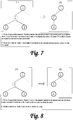
- Figure 7 illustrates the case in which Node 3, the green child of departing Node 2 is Type 1 while the red child of the departing node (Node 4) is Type 0. Node 3 is instructed to connect to Node 1 and Node 4 will be instructed to connect to a node in Node 3's sub-tree based on Node 3's recommended parent list.
- Figure 8 illustrates the case in which both children of departing Node 2 are of Type 0.
- the green child, Node 3 is instructed to connect to Node 1.
- Node 4 must climb its path looking for a home. It first connects to Node 1 and if Node 1 cannot place it, will climb to higher levels of the tree until it reaches the server. If the server cannot place Node 4 it will be rejected from the broadcast tree.
- Figure 9 illustrates the case where Node 3, the green child of departing Node 2, is of Type 2; while Node 4, the red child of the departing node, is of Type 0.
- Node 3 will be instructed by Node 2's depart message to connect to Node 1.
- Node 1 will expect Node 3 based on its own message from Node 2.
- Node 4 will be directed to connect to a location in Node 3's sub-tree (assuming a location is available for a Type 0 to dock) based on Node 3's recommended parent list.
- Figure 10 illustrates a graceful depart of a Type 1 node.
- Node 2 a Type 1 node, executes a graceful client shutdown.
- Node 2 transmits depart messages to its parent, Node 1, and its child, Node 3.
- Node 2's depart message instructs Node 3 to connect to its former grandparent, Node 1.
- Type 1 and Type 0 nodes must register normally at all times. The reason behind this restriction is to prevent Type 1 nodes from bumping Type 2 nodes or higher priority Type 1 nodes. Since nodes that priority join are automatically accepted as a node's red child and that red child is bumped, Type 1 nodes could bump Type 2 nodes if they were allowed to priority join. Since this would work counter to the notion of placing higher level nodes closer to the server, only Type 2 nodes are allowed to priority join.
- Figure 11 through Figure 18 illustrate the reconfiguration behaviors resulting from nodes departing the network in an unexpected (non-graceful) manner.
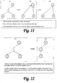
- Figure 11 illustrates the general method for handling unexpected or non-graceful node departures.
- Node 2 the parent of two nodes, Node 3 and Node 4, and the child of Node 1, departs the network in an unexpected and non-graceful manner. Since no depart messages were generated and sent by Node 2 prior to its departure, Node 3 and Node 4 simply lose their connections to Node 2. As each of these nodes become aware that Node 2 no longer exists in the network, via connection time outs or some other means, they will climb to their former grandparent, Node 1. The node that reaches Node 1 first will be connected to Node 1 as its child, replacing the departed Node 2. The slower of the two nodes will be dealt with as described above.
- Figure 12 illustrates the case where both children of the unexpectedly departing node are Type 2.
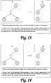
- Figure 13 illustrates the case where the green child of the unexpectedly departing node is Type 2 and the red child is Type 1.
- Figure 14 illustrates the case where both children of the departing node are Type 1.
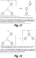
- Figure 15 illustrates the case where the green child is Type 1 and the red child is Type 0.
- Figure 16 illustrates the case where both child nodes of the departing node are Type 0.
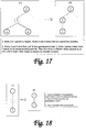
- Figure 17 illustrates the case where the green child is Type 2 and the red child is Type 0.
- Figure 18 illustrates a unexpected (non-graceful) depart of a Type 1 node.
- Node 2 a Type 1 node, departs unexpectedly from the network in a non-graceful manner.
- Node 3 becomes aware of the departure of Node 2 via the connection between the two nodes timing out or by some other means.
- Node 3 climbs its path to its former grandparent Node 1 and Node 1 accepts Node 3 as its child.
- Figure 19 illustrates the case in which the depart message fails to reach the non-preferred (red) child.
- Figure 20 illustrates the case in which the depart message fails to reach the preferred (green) child.
- Figure 21 illustrates the case in which the depart message fails to reach the parent.
- Figure 22 illustrates the case in which the depart messages fail to reach both children.
- Figure 23 illustrates the case in which the depart message fails to reach both the parent and the non-preferred (red) child.
- Figure 24 illustrates the case in which the depart message fails to reach both the parent and the preferred (green) child.
- Figure 25 illustrates the case in which all three messages fail to reach their intended recipients. In this case the graceful depart reverts to the standard non-graceful depart described above.
- NTM Network Topology Model
- This NTM must be maintained even during times of high turnover when nodes are frequently joining and departing the network.
- the parent of a departing node must be able to effectively predict the likely effect on the overall topology of the network its departing child will have.
- the parent node must update its internal NTM to account for connections that will likely be broken and new connections that will likely be formed as a result of the departure of its child from the network.
- a red child (Node C) was assumed able to connect to its green sibling (Node B), and the green child (Node B) was assumed able to accept its red sibling (Node C) as a child, provided the green child (Node B) did not already have two children of its own (Node D and Node E) or if it (Node B) did it (Node B) would be required to bump its existing red child (either Node D or Node E) making room for its (Node B's) incoming red sibling (Node C).
- Node B is departing the network in a graceful manner.
- the parent of Node B, Node A needs to update its internal Network Topology Model to account for the reconfigurations that are likely to occur as a result of Node B's departure.
- the method of U.S. Patent No. 7,035,933 would be: (1) the green child of the departing node connects to its former grandparent, in this particular case Node C connects to Node A, (2) the red child of the departing node cross connects to its green sibling, in this particular case Node D cross connects to Node C, (3) the green child bumps its own red child to make room for its incoming red sibling, in this particular case Node C bumps Node F to accept Node D, (4) the bumped red grandchild of the departing node cross connects to its own green sibling, in this particular case Node F would cross connect to Node E, (5) the green-green grandchild of the departing node would bump its own red child to make room for its incoming red sibling, in this particular case Node E bumps Node J to accept Node F, and finally (6) the bumped red great grandchild of the departing node cross connects to its own green sibling, in this case Node J cross connects to No
- the present system and method includes the following method that allows higher level nodes (such as Node A) to predict the reconfiguration behavior of lower level nodes (such as Node E) in order for the higher level node to update its internal Network Topology Model to reflect the most likely result of a reconfiguration caused by the departure of its child (Node B).
- higher level nodes such as Node A
- lower level nodes such as Node E
- the method consists of having each node periodically propagate up to its parent a description of that node's state (including that node's recommended parent list) together with the state of all nodes located beneath that node and the structure of their relationship to the node in question.
- Node's I and J would propagate their information up to Node E; Node K its information to Node F; Nodes L and M up to Node G; Nodes N and O up to Node H.
- Node E would propagate its information and its children's information (including the fact that Node I is the green child of Node E and Node J is the Red Child of E) to Node C.
- Node F would propagate its information and its child's information to Node C; Nodes G and H their information and their children's information to Node D. Nodes C and D would propagate their information and the information of all of their descendants to Node B, and likewise Node B its information and its descendants information to Node A.
- Node A will have received information from all of the nodes in its entire sub-tree with which to populate its internal network topology model.
- Node B departs the network, Node A will be able to determine the likely result of this departure by consulting the recommended parent lists of the various nodes in its sub-tree.
- Figure 27 illustrates the first two steps of the reconfiguration begun by the graceful departure of Node B.
- Node C connects to Node A, corresponding to the green child connecting to the parent of the departing node; and
- Node D connects to Node C, corresponding to the red child of the departing node cross connecting to its green sibling.
- Node B instructs Node C to connect to Node A, and Node D to connect to Node C.
- Figure 28 illustrates the state of the network immediately following the connection of Node C to Node A and Node D to Node C. Note that Node F, the green-red grandchild of the departing node, has been bumped by Node C in order to make room for Node D to connect.
- Node F wishes to connect to Node E, but unfortunately since Node F is Type 1 and both of Node E's children are Type 2, Node F cannot connect directly to Node E. This issue can be resolved in the following way.
- Node C can consult its Network Topology Model and determine that Node E's recommend parent for incoming nodes will be Node I (as Node I is the green child of Node E) and pass this recommended parent directly to Node F as part of the depart / bump message Node C sends to Node F.
- Node A when updating its own internal Network Topology Model, can predict that Node C will instruct Node F to connect to Node I, as Node A can determine the recommended parents associated with every node in its sub-tree. This allows Node A to update its internal model in accordance with what is likely to happen in the actual network during the reconfiguration events.
- Figure 29 illustrates the final state of the network of Figure 26 following the departure of Node B. Assuming all reconfiguration events resulting from the departure of Node B proceed as planned and there are no other node additions, deletions, or reconfigurations that take place during this time period Figure 29 should be an accurate reflection of both the physical network and Node A's internal Network Topology Model.
- Figure 30 (a) shows the complete network (full tree) prior to the departure of a node.
- Figure 30 (b) illustrates the graceful departure of Node 2 from the network.
- Node 4 is instructed by the departing node to connect to Node 1 and the result can be seen in Figure 30 (c) .
- Node 5 is instructed by the departing node to connect to Node 4.
- the particular type of join Node 5 is instructed to perform with Node 4 is a "priority join" meaning that Node 4 must accept Node 5 (and therefore Node 4 must bump its red child to make room for Node 4).
- Figure 30 (d) illustrates the state of the network after Node 5 is accepted by Node 4. Note that Node 9, the former red child of Node 4, has been bumped.
- Node 4 bumped Node 9 it provided Node 9 with a connection path. That connection path included the recommended parent that Node 9 should attempt to connect to. In this case Node 9 is told by Node 4 to connect to Node 25.
- the reason Node 4 chose Node 25 for Node 9 is that Node 25 is the highest node (closest node to the server) that Node 4 is aware of that can accept a node of Node 9's type.
- Type 1N all that can be bumped by Node 9 are Type 0 nodes - resulting in the candidate parents for Node 9 being Node 35, Node 28, Node 29, and Node 25, of which Node 25 is the closest to the server.
- Figure 30 (e) illustrates the state of the network after Node 9 connects to Node 25. Note that in order for Node 25 to accept Node 9 as a child, it was necessary for node 25 to bump Node 34, a Type 0 Normal Priority node. As part of the bump message, Node 25 instructs Node 34 to attempt to connect to Node 9 (either for a direct connection or for instructions as to where it can connect). Node 34 attempts to connect to Node 9, the root of a Type 1 chain that terminates in a Type 0 Low Priority node (Node 26). Since Node 34's Type 0 Normal Priority out ranks Node 26's Type 0 Low Priority, Node 9 instructs Node 34 to connect to Node 26's parent, Node 17.
- FIG 31 parts (a) - (d), provide a complete example of network reconfiguration following the unexpected (non-graceful) departure of a node.
- Figure 31 (a) illustrates a complete network prior to an unexpected departure of Node 6, a Type 2 Normal Priority node. After the departure of Node 6, its children, Nodes 12 and 13, note its absence. Both Node 12 and Node 13 connect to their grandparent, Node 3. At this point a "race condition" exists between Node 12 and Node 13. Whichever node first connects to Node 3 will be allowed to join as its child. In this case we assume that Node 12 arrives first and is added as a child of Node 3.
- Figure 31 (b) illustrates the state of affairs at this point. Node 13 then attempts to connect to Node 3. Since Node 13 is a Type 1 High Priority node, Node 3 has three potential slots at which it could place Node 13.
- Node 12 is the closest potential parent to the root of the tree, Node 3 tells Node 13 to connect to Node 12. Node 13 then connects to Node 12 causing it to bump Node 21, a Type 1 Normal Priority Node. As Node 12 bumps Node 21, it tells the node to connect to Node 13 for a connection path. The situation at this point is illustrated in Figure 31 (c) .
- Node 13 tells Node 21 to connect to Node 22. Node 21 does so, causing Node 22 to bump its Type 0 Normal Priority child, Node 31.
- Node 31 attempts to connect to Node 21 but is rejected and must climb its path. Eventually, Node 31 finds a home as a child of Node 32.
Landscapes
- Engineering & Computer Science (AREA)
- Computer Networks & Wireless Communication (AREA)
- Signal Processing (AREA)
- Multimedia (AREA)
- Information Transfer Between Computers (AREA)
- Data Exchanges In Wide-Area Networks (AREA)
- Computer And Data Communications (AREA)
Description
- This invention relates to a system for distributing content data over a computer network and a method for arranging nodes for distribution of data over a computer network. The system and method of the present invention are particularly useful for the distribution of streaming audio and video over the Internet.
-
U.S. Patent No. 7,035,933 andUS 2003/0051051 A1 describe a system and method that has proved useful for online distributed broadcasting of audio and video material. The disclosed system and method can reduce the amount of bandwidth consumed by video streaming servers by limiting the server's number of direct connections over the Internet to only a small number of end-consumer computers, and then utilizing a portion of the end-consumer computers that are tuned to the broadcast over the Internet as "repeater nodes" to help propagate the online broadcast to other viewers' computers. This approach to online broadcasting is in contrast to industry standard content delivery networks wherein each end-consumer's computer that is to receive an audio/video stream must establish a direct connection to a server. These servers are typically owned or operated on behalf of the broadcaster and thus the broadcaster is responsible for the bandwidth costs associated with each of these direct connections. - Various embodiments of the system and method disclosed in
U.S. Patent 7,035,933 display the following highly desirable traits: - The network architecture is based on a balanced binary tree and as such is tailored to deliver live broadcasts, not simply pre-recorded material as is the case with peer-to-peer networks, such as BitTorrent and the like.
- The network architecture supports the addition of nodes (computers) as end-consumers tune in to the broadcast and the removal of nodes (computers) as end-consumers exit the broadcast. As a result, the invention does not need to run as a "background task" nor continuously tap into end-consumer's bandwidth as with peer-to-peer file sharing technologies. Instead the invention of
US Patent 7,035,933 need only use an end-consumer's bandwidth while that end-consumer is tuned to a program. - The system and method disclosed in
U.S. Patent 7,035,933 does not store audio video content files on end-consumers' computers. This is in contrast to peer-to-peer file sharing systems which to work effectively must cache content throughout the network. - Because the system and method disclosed in
US Patent 7,035,933 is based on a balanced binary tree, only one half of the nodes (end-consumer computers) in the network need act as repeater nodes in order for the system to achieve maximum bandwidth savings efficiency. This enables software applications incorporating this invention to be "polite" in the sense that whenever an end-consumer's computer is acting as a repeater node and that end-consumer needs to use his or her upstream bandwidth for other purposes (such as email, gaming, or Voice Over IP [VOIP] applications) that end-consumer's computer is moved to the edge of the network where it will no longer be expected to retransmit the broadcast. This reorganization of the network can take place without interrupting the end-consumer's viewing experience. The end result is a polite system that immediately relinquishes use of the end-consumer's upstream bandwidth the moment the end-consumer has need of that bandwidth for other purposes. In other words, the invention does not interfere with the end-consumers use of his or her Internet connection since the moment the end-consumer tries to send off a file (or otherwise use the upstream Internet connection) applications incorporating the invention relinquish control of the upstream Internet connection immediately. The bottom line is that end-consumer see no degradation in their Internet service when using applications based on the invention. - The system and method disclosed in
U.S. Patent 7,035,933 spreads the bandwidth needs of the system thinly throughout the network - never requiring an end-consumer computer to supply more than two copies of the video stream to other viewers. As a result the system avoids "super-noding" in which nodes (computers) with access to large amounts of bandwidth are expected to provide copies of the broadcast stream to large numbers of viewers. Not only is expecting certain computers to act as super nodes impolite, there are two very important reasons for avoiding it. First, if an application attempts to appropriate a large amount of bandwidth when running on corporate or university LANs the system administrators of those networks will take steps to block the application - which will result in potential viewers on corporate and university LANs from being able to run the application to watch video. The second reason to avoid designating certain computers as super nodes is that systems which depend on a small number of nodes to support a large percentage of the system's viewers are fragile in the sense that when a super node departs the system a large "hole" is created in the network that must somehow be "filled in" almost immediately or large numbers of viewers will experience signal degradation and loss of video stream. - The system and method of
US Patent 7,035,933 delivers an exceptional Quality of Service. In addition to the characteristics described above, the reconfiguration algorithms covered by the patent use the turnover inherent in distributed networks (as viewers tune in and tune out) to promote the most reliable nodes to the most critical regions of the network, driving the network towards highly stable configurations which improve the quality of service delivered by the system. - The system and method of
US Patent 7,035,933 also suffers from certain limitations, including the fact that the reconfiguration algorithms are described in detail only for binary trees in which all internal nodes must be capable of supporting two children nodes. This means that for a node (an end-consumer computer) to be used to repeat the broadcast stream to even a single additional computer, the node must have the upstream bandwidth capacity to support two additional computers. As a result, nodes (end-consumer computers) that only have access to Internet connections with upstream bandwidth capacity to send out a single copy of the broadcast stream are underutilized - they are never allowed to repeat the broadcast to anyone. - The practical consequences of these limitations are that for a given video streaming bit rate and a collection of nodes (end-consumer computers) possessing a variety of different upstream bandwidth capabilities, some nodes that could have been employed to rebroadcast the video stream will not be asked to do so, reducing the overall bandwidth efficiency that could have been otherwise achieved. Likewise for a given bandwidth efficiency target, a higher bit rate video stream could be supported, resulting in better picture quality and/or audio for the end- consumer.
- Incorporating such a change into the system and method of
US Patent 7,035,933 requires addressing the difficult problem of how to build and maintain a binary broadcast tree with repeat capable nodes of differing abilities must be addressed, in order to create a useful and practical online broadcasting system, algorithms must be designed to build and maintain binary broadcast trees consistent with promoting the most reliable nodes to the most critical regions of the network (to promote stability) while maintaining overall tree balance (to limit propagation delays) and employing nodes that lack the ability to repeat to two children but possess the ability to repeat to a single child (to increase overall network efficiency). -
WO 2006/010111 A2 describes systems for distributing data over a computer network and methods for arranging nodes. -
WO 03/039053 A2 - In an embodiment, the invention provides a method for efficiently utilizing end-consumer computers possessing a variety of upstream bandwidth capabilities to deliver online streaming video in a distributed manner.
- The foregoing and other objects, features, and advantages of the invention will be apparent from the following more particular description of preferred embodiments as illustrated in the accompanying drawings, in which reference characters refer to the same parts throughout the various views. The drawings are not necessarily to scale, emphasis instead being placed upon illustrating principles of the invention.
-
FIG. 1 is a schematic drawing of an embodiment of a computer information distribution network formed pursuant to an embodiment of the present system and method; -
FIG. 2 is an illustration of the method used to merge two linear chains of nodes upon the departure of aType 2 node; -
FIG. 3 is an illustration of the general method used to reconfigure the network in the case of the graceful departure of aType 2 node; -
FIG. 4 is an illustration of the general method used to reconfigure the network in the case of the graceful departure of aType 2 node with twoType 2 children; -
FIG. 5 is an illustration of the general method used to reconfigure the network in the case of the graceful departure of aType 2 node with oneType 2 child and oneType 1 Child, where theType 2 Child is the preferred (green) child; -
FIG. 6 is an illustration of the general method used to reconfigure the network in the case of the graceful departure of aType 2 node with twoType 1 children; -
FIG. 7 is an illustration of the general method used to reconfigure the network in the case of the graceful departure of aType 2 node with oneType 1 child and one Type 0 Child, where theType 1 Child is the preferred (green) child; -
FIG. 8 is an illustration of the general method used to reconfigure the network in the case of the graceful departure of aType 2 node with two Type 0 children; -
FIG. 9 is an illustration of the general method used to reconfigure the network in the case of the graceful departure of aType 2 node with oneType 2 child and one Type 0 Child, where theType 2 Child is the preferred (green) child; -
FIG. 10 is an illustration of the general method used to reconfigure the network in the case of the graceful departure of aType 1 node where thatType 1 node has a child; -
FIG. 11 is an illustration of the general method used to reconfigure the network in the case of the unexpected (non-graceful) departure of aType 2 node; -
FIG. 12 is an illustration of the general method used to reconfigure the network in the case of the unexpected (non-graceful) departure of aType 2 node with twoType 2 children; -
FIG. 13 is an illustration of the general method used to reconfigure the network in the case of the unexpected (non-graceful) departure of aType 2 node with oneType 2 child and oneType 1 Child, where theType 2 Child is the preferred (green) child; -
FIG. 14 is an illustration of the general method used to reconfigure the network in the case of the unexpected (non-graceful) departure of aType 2 node with twoType 1 children; -
FIG. 15 is an illustration of the general method used to reconfigure the network in the case of the unexpected (non-graceful) departure of aType 2 node with oneType 1 child and one Type 0 Child, where theType 1 Child is the preferred (green) child; -
FIG. 16 is an illustration of the general method used to reconfigure the network in the case of the unexpected (non-graceful) departure of aType 2 node with two Type 0 children; -
FIG. 17 is an illustration of the general method used to reconfigure the network in the case of the unexpected (non-graceful) departure of aType 2 node with oneType 2 child and one Type 0 Child, where theType 2 Child is the preferred (green) child; -
FIG. 18 is an illustration of the general method used to reconfigure the network in the case of the unexpected (non-graceful) departure of aType 1 node where thatType 1 node has a child; -
FIG. 19 is an illustration of the general method used to reconfigure the network in the case of a departure of aType 2 node with two children where the depart message is not received by the non-preferred (red) child; -
FIG. 20 is an illustration of the general method used to reconfigure the network in the case of a departure of aType 2 node with two children where the depart message is not received by the preferred (green) child; -
FIG. 21 is an illustration of the general method used to reconfigure the network in the case of a departure of aType 2 node with two children where the depart message is not received by the parent of the departing node; -
FIG. 22 is an illustration of the general method used to reconfigure the network in the case of a departure of aType 2 node with two children where depart messages are not received by either of the two children; -
FIG. 23 is an illustration of the general method used to reconfigure the network in the case of a departure of aType 2 node with two children where depart messages are not received by either the parent of the departing node nor the departing node's non-preferred (red) child; -
FIG. 24 is an illustration of the general method used to reconfigure the network in the case of a departure of aType 2 node with two children where depart messages are not received by either the parent of the departing node nor the departing node's preferred (green) child; -
FIG. 25 is an illustration of the general method used to reconfigure the network in the case of a departure of aType 2 node with two children where depart messages are not received by either the parent of the departing node nor the departing node's two children; -
FIG. 26 is an illustration of a network in which Node B is departing gracefully; -
FIG. 27 is an illustration of the first two steps in the reconfiguration of the network illustrated inFigure 26 following the departure of Node B; -
FIG. 28 is an illustration of the state of the network following the connection of Node C to Node A and Node D to Node C; -
FIG. 29 is an illustration of the final state of the network ofFigure 26 following the departure of Node B; -
FIG. 30 (a-f) illustrates the reconfigurations that result from the graceful departure of a node; -
FIG. 31 (a-d) illustrates the reconfigurations that result from the unexpected (non-graceful) departure of a node. - Reference will now be made in detail to the preferred embodiments of the present invention, examples of which are illustrated in the accompanying drawings.
- The invention is described below with reference to block diagrams and operational illustrations of methods and devices for distributing content data over a computer network. It is understood that each block of the block diagrams or operational illustrations, and combinations of blocks in the block diagrams or operational illustrations, may be implemented by means of analog or digital hardware and computer program instructions. These computer program instructions may be provided to a processor of a general purpose computer, special purpose computer, ASIC, or other programmable data processing apparatus, such that the instructions, which execute via the processor of the computer or other programmable data processing apparatus, implements the functions/acts specified in the block diagrams or operational block or blocks. In some alternate implementations, the functions/acts noted in the blocks may occur out of the order noted in the operational illustrations. For example, two blocks shown in succession may in fact be executed substantially concurrently or the blocks may sometimes be executed in the reverse order, depending upon the functionality/acts involved.
- In the system and method of
US Patent 7,035,933 there were essentially two kinds of nodes: repeat capable nodes and non-repeat capable nodes. A node was deemed "repeat capable" if it possessed the upstream bandwidth capacity to support two outgoing audio/video streams plus some pre-defined additional capacity for overhead and margin. If a node did not have the capacity to support two children it was deemed non-repeat capable. - As pointed out above, this bifurcation of nodes was somewhat wasteful in that nodes fully capable of supporting a single child were not utilized by the system due to the inability of the reconfiguration algorithms to accommodate nodes capable of supporting only a single child.
- In the present system and method there are three main types of nodes:
Type 2 nodes,Type 1 nodes, and Type 0 nodes. As their names imply,Type 2 nodes are capable of supporting two children,Type 1 nodes are capable of supporting a single child, and Type 0 nodes are incapable of supporting any children. - In addition to these three major types, within a type various priorities may exist. The defined priorities are High, Normal, and Low. Each of these priorities does not necessarily exist for each of the types.
- The type and priority of a node together define that node's preference level. The defined preference levels for nodes are as follows:
-
Type 2, Normal Priority (sometimes written as T2N) is the highest priority node known to the system. These nodes are capable of supporting two children and are roughly equivalent to "repeat capable" nodes in the previous system and method. -
Type 1, High Priority (sometimes written as T1H) are capable of supporting a single child. At some point in their past T1H nodes were categorized asType 2, but were later "demoted" to Type 1 - generally as a result of poor performance when serving as the parent of two children.Type 1 High Priority are given preference overother Type 1 nodes in order to keep theType 1 High Priority nodes as high in the tree as possible (just below the Type 2). This is due to the fact that we expect these nodes to be "stronger" thannormal Type 1's and also so that if aType 1 High Priority converts back to aType 2 Normal node it will already be situated "near" theType 2 nodes. -
Type 1 Normal Priority is the third preference level of node that the system recognizes. Nodes whose upstream bandwidth tested capable of supporting one child but not two are given this rating when they join the network. - Type 0 High Priority is the fourth preference level of node that the system recognizes. These nodes are currently judged incapable of repeating to even a single child, however they were at one
time Type 1. Type 0 High Priority are given preference over Type 0 Normal and Type 0 Low as they have a history of having been a productive node and therefore should be retained in the tree as much as possible in case they reconvert toType 1 status again. - Type 0 Normal Priority is the fifth preference level of node that the system recognizes. The only type of node a Type 0 Normal can theoretically bump is a Type 0 Low priority. Type 0 Normal priority nodes correspond to the "non-repeat capable" nodes from the previous system and method. Nodes whose upstream bandwidth test too low to act as a repeater of even a single stream when the node joins the network are given this designation.
- Type 0 Low Priority nodes are the sixth and lowest preference level of node recognized by the system. These nodes are incapable of bumping nodes of any type. A Type 0 node may be assigned "low priority" status for a number of reasons, such as an inability to reliably receive data from its parent node.
- The fundamental rule concerning node type is that a node of a particular preference level may not bump a node at an equal or greater preference level, but may always bump a node at a lesser preference level. (The one exception to this rule is that
Type 2 Normal nodes may causeother Type 2 Normal nodes to be bumped when executing priority and system joins, as explained below.) - Thus, except as stipulated in the previous paragraph,
Type 2 Normal nodes may bump all nodes exceptother Type 2 Normal nodes. AType 1 High Priority may not bumpType 2 Normal orother Type 1 High Priority nodes, but may bumpType 1 Normal Priority, Type 0 High Priority, Type 0 Normal Priority, and Type 0 Low priority. Likewise,Type 1 Normal Priority nodes cannot bumpType 2 Normal,Type 1 High, orother Type 1 Normal Priority nodes, but are free to bump all Type 0 nodes regardless of their "priority". Similarly, Type 0 High priority nodes cannot bumpType 2,Type 1, or other Type 0 High Priority nodes, but can bump Type 0 Normal and Type 0 Low priority nodes. Type 0 Normal can only bump Type 0 Low, and Type 0 Low can bump no one. -
Figure 1 illustrates a complete distributed broadcast tree constructed according to the methods of the present system and method. - An innovation present in this system and method over that of
U.S. Patent No. 7,035,933 is the ability to form and maintain linear chains of nodes composed of nodes that are capable of broadcasting to only one child. These linear chains may be capped by nodes that are incapable of broadcasting to any nodes - Another innovation present in this system and method is the demarcation of one side of the binary tree as "Primary" and the other side as "Secondary". The primary side of the tree, shown as the left, or green, side of the tree in
Figure 1 , is where the system prefers to place nodes. The secondary side of the tree, shown as the right, or red, side of the tree inFigure 1 is used to temporarily hold excess linear chains that cannot be accommodated in the Primary side of the tree. - A difference between the primary and secondary sides of the tree is that the capacity of the secondary side can be increased on an as-needed basis by the addition of VTT (Virtual Tree Top) nodes. VTT nodes are "virtual" nodes introduced into the binary tree to expand the "capacity" of the tree. VTT nodes map in the physical world to additional connections to the server. Hence, while a classical binary tree can only have two nodes connected directly to the root node / physical server, the use of VTT nodes allow for an arbitrary number of physical connections to the server. While VTT nodes have been described in previous applications related to
U.S. Patent No. 7,035,933 , we extend their use to being generated dynamically based on the number and type of nodes present in a broadcast network. - An important use of the Secondary side of the tree and use of dynamic VTT is to prevent individual linear chains from growing exceedingly long leading to an unbalanced tree.
- As described elsewhere in this document, it is frequently desirable in the present system and method to merge linear chains of
Type 1 nodes. If left unchecked, networks withfew Type 2 nodes andmany Type 1 nodes could devolve into a small number of very long chains. Long chains should be avoided as they lead to propagation delays. Additionally, large numbers of repeaters between an individual node (such as an edge node or node near the edge of the tree) and the server increase the likelihood of Quality of Service issues - since the "signal" is passing through a large number of "repeaters" each given to failure. - To limit the length of
Type 1 chains in networks withfew Type 2 repeaters, we define the concept of "long". Long, which may be a dynamic definition that is dependent on the total number of nodes, the total number of a particular type of node, the percentage of certain node types, ratios of the various node types, or other dynamic features of the network, is used to limit the total length ofType 1 chains. Whenever a merger of two linear chains is to be performed, if the length of the chain resulting from the merger were to exceed "long" the merge will not be performed and instead one of the linear chains would be moved to the Secondary side of the tree. - To prevent the secondary side of the tree from becoming saturated, additional VTT nodes are created as necessary to act as docking locations for additional
linear Type 1 chains. However, a maximum saturation point may be defined which specifies the maximum number of VTT nodes allowable on the Secondary side of the tree. - Whenever a node with children leaves the broadcast network (or tree), the reconfiguration algorithms decide where to place the children of the departing node as well any node chains associated with those children.
- There are two basic types of ways in which a node may leave the broadcast network (or tree) : Graceful Departs, and Unexpected or Non-Graceful Departs.
- The term "Graceful Depart" refers to a normal or procedural shutdown of the client application - the type of departure that is generated when the end-user clicks on the "x" in the upper right hand corner of the client interface in order to exit the application. When a graceful depart is initiated, all shutdown procedures are then completed. The departing node sends a depart message to its children and parent with instructions on how they are to proceed. The children of the departing node send out depart propagate packets to their children. These packets are updated at each level and propagated throughout the sub-trees.
- The term "Unexpected or Non-Graceful Depart" refers to a node leaving the system in an unexpected manner - without the normal shutdown procedures being performed. A non-graceful depart can occur for any number of reasons: the computer that is running the client application may lose its Internet connection, or the machine running the client application may crash, or the end-user abnormally terminates the client application by "killing" it with Task Manager, etc. Generally, when an unexpected depart occurs, the children of the departing node will climb to their grandparent for instructions on how to proceed.
- In addition to nodes leaving the network altogether by way of graceful and non-graceful departs, a node that remains in the network (tree) can change its position by disconnecting from its current parent and reconnecting to some other parent. These reconnections can be voluntary or involuntary in response to changing conditions in the network.
- One type of reconfiguration event is a "Bump". The term "Bump" refers to a node being forcibly kicked by its parent so that the parent can accept a higher priority node in the bumped node's place. When the parent kicks the bumped node, it also tells the bumped node where to go next.
- A "Priority Join" is a way to force reconfiguration. When a node registers with the priority join flag set, the node that it registers to kicks its red child and accepts the registering node as its new red child. Priority joins are only allowed for
Type 2 nodes. - A "System Join" is a way to force a priority join in a non-graceful reconfiguration. A system join is triggered when a
Type 2 node with children registers with a node that cannot accept it as a child. During a system join, the joining node is told to priority join to the red child of the node with which it is trying to register. - Two additional terms that are frequently used when discussing reconfiguration are: the "Recommended Parent List" and the "Network Topology Model" or NTM.
- A node's Recommended Parent list is a list of all nodes known to that node that can act as parent nodes. The Recommended Parent list will vary from node to node as an individual node can only recommend parents that are within its own sub-tree. The Recommended Parent list is usually sorted (or organized in some way) so as to make finding the "best" recommended parent easy to accomplish. The "best" recommended parent will generally be the recommended parent that is closest to the server (the root of the broadcast tree).
- The Network Topology Model (or NTM) is a node's internal model of the structure of the portion of the network of which the node is aware. A node's NTM generally consists of a path from the root / server node down to the node in question, together with the sub-tree of the overall network tree that is rooted at the node. Network Topology Models are generally annotated with state information about the nodes contained in the model, such as the recommended parent lists of all nodes in the sub-tree. A node uses its NTM to determine where to place incoming nodes that attempt to connect to the node in question.
- Merging is the process of combining two chains of
Type 1 Nodes where each chain may or may not be capped with a Type 0 node. When a node directly supporting two node chains departs the network, either gracefully or non-gracefully, its two chains may be merged as long as their combined length does not exceed the pre-defined value for "long". -
Figure 2 illustrates the node chain merger process. InitiallyNode 2 is the parent of twoType 1 nodes,Node 4, aType 1 High Priority, is the green child of the departing node andNode 5, also aType 1 High Priority, is the red child of the departing node.Node 4 is the root of a chain ofType 1 nodes (Node 4,Node 8,and Node 12) capped by a Type 0 node,Node 14. Similarly,Node 5 is the root of aType 1 chain (Node 5 and Node 9) capped by a Type 0 node,Node 13. -
Node 2 departs the network leaving behind the two node chains. AsNode 4 is the green child of the departing node it will be instructed to connect to its former grandparent,Node 1.Node 5 will be instructed to connect into the chain rooted byNode 4 immediately below thelowest Type 1 High Priority node. Since there is only oneType 1 High Priority node in the chain rooted atNode 4,Node 5 will connect to that node, which happens to beNode 4. - In order to accept
Node 5,Node 4 was forced to bump itsType 1 Normal child,node 8. During the bump ofNode 8 byNode 4,Node 4 will have instructedNode 8 to connect toNode 5 for further instructions. SinceNode 8 isType 1 Normal it cannot become a child ofNode 5, insteadNode 5 instructsNode 8 to connect as a child ofNode 9.Node 8 connects toNode 9, causing Node 13 a Type 0 Low Priority node to be bumped. -
Node 13 then attempts to connect toNode 8, but sinceNode 13 is Type 0 Low which is incapable of bumping anyone and the chain headed byNode 8 terminates in a Type 0 High (Node 14),Node 13 is rejected and must climb its path, beginning at thefirst Type 2 node and working upwards towards the root server until it can either be placed or rejected completely from this broadcast tree. - Thus the two linear chains have now been completely merged into a single chain, with the level of nodes respected -
Type 1 High Priority nodes situated aboveType 1 Normal Priority Nodes and Type 0 High Priority retained in preference to Type 0 Normal or Low priority. - Whenever a departing node completes its shutdown procedure, it sends a depart message to its children and parent. The green child of the departing node is instructed to connect to the parent of the departing node. If there is a red child, a decision has to be made as to what to do with this red child based upon the type of the red child. If the red child is a
Type 2, the departing node may tell the red child to priority join to its sibling. If the child is aType 1 or a Type 0, then the departing node sends the red child a connection path based on the recommended parent list of its green sibling. If there is no place for theType 1 or Type 0 red child to be placed in the green child's sub-tree, then the departing node will tell theType 1 or Type 0 red child to climb its path. -
Figure 3 through Figure 10 illustrate the expected reconfiguration behavior resulting from nodes departing the network in a graceful manner. - In
Figure 3 , the end-user whose client application is identified asNode 2 clicks the "X" in the upper right hand corner of the client or otherwise instructs the application to exit. As part of its close out procedure,Node 2 constructs depart messages which contain information instructing thenodes surrounding Node 2 what actions they are to take.Node 3 receives a message fromNode 2 instructing it to connect to its former grandparent,Node 1.Node 1 receives a message fromNode 2 instructing it to expectNode 3 to connect to it as a replacement forNode 2.Node 4 receives a message fromNode 2 containing instructions as to where it should connect as described above. Depending on the type and number ofchildren Node 3 already supports as well as the type ofNode 4,Node 4 may connect directly as a child ofNode 3, somewhere in the sub-tree rooted atNode 3, elsewhere in the network, or even under rare circumstances be rejected completely if there is no available location to which it can dock. -
Figure 4 illustrates the case in which both children (Node 3 and Node 4) of the departing node,Node 2, areType 2. In thiscase Node 3 is instructed to connect toNode 1 andNode 4 is instructed to connect toNode 3. This type of reconfiguration is similar to standard reconfiguration in theU.S. Patent No. 7,035,933 . -
Figure 5 illustrates the case in which the preferred (green) child (Node 3) of the departing node isType 2, while the non-preferred (red) child (Node 4) of the departing node isType 1. In this case,Node 3 will connect to itsformer grandparent Node 1, whileNode 4 will be instructed to connect to a node inNode 3's sub-tree based onNode 3's recommended parent list. -
Figure 6 illustrates the case in which both children of the departing node areType 1 nodes. In this case,Node 3 will connect toNode 1 andNode 4 will be instructed to connect to a node inNode 3's sub-tree based onNode 3's recommended parent list. Note that ifNode 3 andNode 4 were the heads of linear chains, a chain merger would occur using the method illustrated inFigure 2 and described above. -
Figure 7 illustrates the case in whichNode 3, the green child of departingNode 2 isType 1 while the red child of the departing node (Node 4) is Type 0.Node 3 is instructed to connect toNode 1 andNode 4 will be instructed to connect to a node inNode 3's sub-tree based onNode 3's recommended parent list. -
Figure 8 illustrates the case in which both children of departingNode 2 are of Type 0. The green child,Node 3, is instructed to connect toNode 1. However the red child,Node 4, must climb its path looking for a home. It first connects toNode 1 and ifNode 1 cannot place it, will climb to higher levels of the tree until it reaches the server. If the server cannot placeNode 4 it will be rejected from the broadcast tree. -
Figure 9 illustrates the case whereNode 3, the green child of departingNode 2, is ofType 2; whileNode 4, the red child of the departing node, is of Type 0. In this case,Node 3 will be instructed byNode 2's depart message to connect toNode 1.Node 1 will expectNode 3 based on its own message fromNode 2.Node 4 will be directed to connect to a location inNode 3's sub-tree (assuming a location is available for a Type 0 to dock) based onNode 3's recommended parent list. -
Figure 10 illustrates a graceful depart of aType 1 node.Node 2, aType 1 node, executes a graceful client shutdown. As aresult Node 2 transmits depart messages to its parent,Node 1, and its child,Node 3.Node 2's depart message instructsNode 3 to connect to its former grandparent,Node 1. - When an unexpected or non-graceful depart occurs, such as happens when a node loses its connection to its parent, the children of the departing node will climb their path to their former grandparent for placement. The first child that registers with its former grandparent is accepted. The second child that registers with its grandparent will take different actions based on its type. If the slower child is a
Type 2 and has children, that node will do a system join to its grandparent. The grandparent will instruct the joining node to priority join to the grandparent's red child. Otherwise, the second child will follow the normal registration procedure. If the second child is aType 1 or Type 0, the grandparent places it as if it were just entering the network. The node may not priority join, as priority join functionality is reserved only forType 2 nodes.Type 1 and Type 0 nodes must register normally at all times. The reason behind this restriction is to preventType 1 nodes from bumpingType 2 nodes orhigher priority Type 1 nodes. Since nodes that priority join are automatically accepted as a node's red child and that red child is bumped,Type 1 nodes could bumpType 2 nodes if they were allowed to priority join. Since this would work counter to the notion of placing higher level nodes closer to the server, onlyType 2 nodes are allowed to priority join. -
Figure 11 through Figure 18 illustrate the reconfiguration behaviors resulting from nodes departing the network in an unexpected (non-graceful) manner. -
Figure 11 illustrates the general method for handling unexpected or non-graceful node departures.Node 2, the parent of two nodes,Node 3 andNode 4, and the child ofNode 1, departs the network in an unexpected and non-graceful manner. Since no depart messages were generated and sent byNode 2 prior to its departure,Node 3 andNode 4 simply lose their connections toNode 2. As each of these nodes become aware thatNode 2 no longer exists in the network, via connection time outs or some other means, they will climb to their former grandparent,Node 1. The node that reachesNode 1 first will be connected toNode 1 as its child, replacing the departedNode 2. The slower of the two nodes will be dealt with as described above. -
Figure 12 illustrates the case where both children of the unexpectedly departing node areType 2.Figure 13 illustrates the case where the green child of the unexpectedly departing node isType 2 and the red child isType 1.Figure 14 illustrates the case where both children of the departing node areType 1.Figure 15 illustrates the case where the green child isType 1 and the red child is Type 0.Figure 16 illustrates the case where both child nodes of the departing node are Type 0.Figure 17 illustrates the case where the green child isType 2 and the red child is Type 0. -
Figure 18 illustrates a unexpected (non-graceful) depart of aType 1 node.Node 2, aType 1 node, departs unexpectedly from the network in a non-graceful manner.Node 3 becomes aware of the departure ofNode 2 via the connection between the two nodes timing out or by some other means.Node 3 climbs its path to itsformer grandparent Node 1 andNode 1 acceptsNode 3 as its child. - When a client is shutdown gracefully, it sends out the depart messages to each of its kids and its parent. However, there is no guarantee that these messages will be received by their intended recipients.
Figure 19 through Figure 25 illustrate the consequences of the failure of various messages to reach their intended recipients. -
Figure 19 illustrates the case in which the depart message fails to reach the non-preferred (red) child.Figure 20 illustrates the case in which the depart message fails to reach the preferred (green) child.Figure 21 illustrates the case in which the depart message fails to reach the parent.Figure 22 illustrates the case in which the depart messages fail to reach both children.Figure 23 illustrates the case in which the depart message fails to reach both the parent and the non-preferred (red) child.Figure 24 illustrates the case in which the depart message fails to reach both the parent and the preferred (green) child. -
Figure 25 illustrates the case in which all three messages fail to reach their intended recipients. In this case the graceful depart reverts to the standard non-graceful depart described above. - When Node A sends a message to Node B requesting that Node A be placed in the broadcast tree, it is necessary that Node B have access to an internal Network Topology Model (NTM) that reflects the overall state of the network with enough fidelity to assign Node A to a parent node consistent with maintaining the key properties of the network, such as maintaining approximate tree balance and placing stronger nodes as high in the tree (as close to the server) as practical.
- This NTM must be maintained even during times of high turnover when nodes are frequently joining and departing the network. To that end, the parent of a departing node must be able to effectively predict the likely effect on the overall topology of the network its departing child will have. In other words, the parent node must update its internal NTM to account for connections that will likely be broken and new connections that will likely be formed as a result of the departure of its child from the network. These effects are not necessarily localized and may propagate throughout the sub-tree rooted at the parent all the way to the edge of the network.
- In the system and method of
US Patent 7,035,933 reconfigurations to a node's local copy of the NTM for the parent of a departing node involved recursively following the green path of the parent's sub-tree and having red children connect to their green siblings. This elegant approach emerged from the system requirement that all nodes could either repeat to two children or not at all -- and that, aside from greenness / redness, all repeaters were essentially equal. Thus, a red child (Node C) was assumed able to connect to its green sibling (Node B), and the green child (Node B) was assumed able to accept its red sibling (Node C) as a child, provided the green child (Node B) did not already have two children of its own (Node D and Node E) or if it (Node B) did it (Node B) would be required to bump its existing red child (either Node D or Node E) making room for its (Node B's) incoming red sibling (Node C). In cases where the red sibling was not capable of repeating to two children and the red child of the green sibling was also a not capable of repeating to two children, reconfigurations were allowed to continue as described above with the understanding that the green sibling in reality would simply reject the connection request from the red sibling as a non-repeat capable node was not allowed to bump another non repeat capable node. The difference between the outcomes of the NTM reconfiguration and the reality of the network-level request logic was allowed to persist, because the difference did not affect the structure of the NTM as far as placement of new nodes was concerned. - With the complexity of the new placement logic for the present system and method, reconfiguration must solve issues that didn't exist before. In the present system and method, all repeat capable nodes are not essentially equal as they were in
US Patent 7,035,933 . Some repeat capable nodes can support two children (Type 2 nodes) while other repeat capable nodes can support only one child (Type 1 nodes). Of the repeat capable nodes that can only support one child, there is the additional consideration of its priority. AType 1 node of normal priority (e.g., a T1N) cannot be the parent of aType 1 of a higher priority (e.g., a T1H), and noType 1 node, regardless of its priority, may become the parent of aType 2 node. - Consider the situation illustrated in
Figure 26 . Node B is departing the network in a graceful manner. The parent of Node B, Node A, needs to update its internal Network Topology Model to account for the reconfigurations that are likely to occur as a result of Node B's departure. - In one embodiment, the method of
U.S. Patent No. 7,035,933 would be: (1) the green child of the departing node connects to its former grandparent, in this particular case Node C connects to Node A, (2) the red child of the departing node cross connects to its green sibling, in this particular case Node D cross connects to Node C, (3) the green child bumps its own red child to make room for its incoming red sibling, in this particular case Node C bumps Node F to accept Node D, (4) the bumped red grandchild of the departing node cross connects to its own green sibling, in this particular case Node F would cross connect to Node E, (5) the green-green grandchild of the departing node would bump its own red child to make room for its incoming red sibling, in this particular case Node E bumps Node J to accept Node F, and finally (6) the bumped red great grandchild of the departing node cross connects to its own green sibling, in this case Node J cross connects to Node I. - The problem with the method of
U.S. Patent No. 7,035,933 is that it does not account for the fact that Node F cannot connect to Node E since Node F is aType 1 node and both of Node E's children areType 2. In the system of the present system andmethod Type 1 nodes cannot bumpType 2 nodes. - Thus the present system and method includes the following method that allows higher level nodes (such as Node A) to predict the reconfiguration behavior of lower level nodes (such as Node E) in order for the higher level node to update its internal Network Topology Model to reflect the most likely result of a reconfiguration caused by the departure of its child (Node B).
- The method consists of having each node periodically propagate up to its parent a description of that node's state (including that node's recommended parent list) together with the state of all nodes located beneath that node and the structure of their relationship to the node in question. Thus for example referring to
Figure 26 , Node's I and J would propagate their information up to Node E; Node K its information to Node F; Nodes L and M up to Node G; Nodes N and O up to Node H. Node E would propagate its information and its children's information (including the fact that Node I is the green child of Node E and Node J is the Red Child of E) to Node C. Likewise Node F would propagate its information and its child's information to Node C; Nodes G and H their information and their children's information to Node D. Nodes C and D would propagate their information and the information of all of their descendants to Node B, and likewise Node B its information and its descendants information to Node A. - In this manner, Node A will have received information from all of the nodes in its entire sub-tree with which to populate its internal network topology model. Thus, when Node B departs the network, Node A will be able to determine the likely result of this departure by consulting the recommended parent lists of the various nodes in its sub-tree.
- It should be noted at this point, that a particular node's internal model of the network may not be completely accurate as configuration changes may have taken place at lower levels and those changes may not have yet propagated up to the node in question. Regardless of this limitation, the information provided is judged "good enough" for making placement decisions and predictions as to network state following child departure.
- Continuing with the example begun in
Figure 26 ,Figure 27 illustrates the first two steps of the reconfiguration begun by the graceful departure of Node B. Node C connects to Node A, corresponding to the green child connecting to the parent of the departing node; and Node D connects to Node C, corresponding to the red child of the departing node cross connecting to its green sibling. In point of fact, as illustrated inFigure 4 , Node B instructs Node C to connect to Node A, and Node D to connect to Node C. -
Figure 28 illustrates the state of the network immediately following the connection of Node C to Node A and Node D to Node C. Note that Node F, the green-red grandchild of the departing node, has been bumped by Node C in order to make room for Node D to connect. - Node F wishes to connect to Node E, but unfortunately since Node F is
Type 1 and both of Node E's children areType 2, Node F cannot connect directly to Node E. This issue can be resolved in the following way. When Node F is bumped by Node C, Node C can consult its Network Topology Model and determine that Node E's recommend parent for incoming nodes will be Node I (as Node I is the green child of Node E) and pass this recommended parent directly to Node F as part of the depart / bump message Node C sends to Node F. - Node A, when updating its own internal Network Topology Model, can predict that Node C will instruct Node F to connect to Node I, as Node A can determine the recommended parents associated with every node in its sub-tree. This allows Node A to update its internal model in accordance with what is likely to happen in the actual network during the reconfiguration events.
-
Figure 29 illustrates the final state of the network ofFigure 26 following the departure of Node B. Assuming all reconfiguration events resulting from the departure of Node B proceed as planned and there are no other node additions, deletions, or reconfigurations that take place during this time periodFigure 29 should be an accurate reflection of both the physical network and Node A's internal Network Topology Model. -
Figure 30 , parts (a) - (f), provide a complete example of network reconfiguration following the graceful departure of a node. -
Figure 30 (a) shows the complete network (full tree) prior to the departure of a node.Figure 30 (b) illustrates the graceful departure ofNode 2 from the network.Node 4 is instructed by the departing node to connect toNode 1 and the result can be seen inFigure 30 (c) .Node 5 is instructed by the departing node to connect toNode 4. The particular type ofjoin Node 5 is instructed to perform withNode 4 is a "priority join" meaning thatNode 4 must accept Node 5 (and thereforeNode 4 must bump its red child to make room for Node 4).Figure 30 (d) illustrates the state of the network afterNode 5 is accepted byNode 4. Note thatNode 9, the former red child ofNode 4, has been bumped. WhenNode 4 bumpedNode 9 it providedNode 9 with a connection path. That connection path included the recommended parent thatNode 9 should attempt to connect to. In thiscase Node 9 is told byNode 4 to connect toNode 25. Thereason Node 4 choseNode 25 forNode 9 is thatNode 25 is the highest node (closest node to the server) thatNode 4 is aware of that can accept a node ofNode 9's type. Note that being of Type 1N, all that can be bumped byNode 9 are Type 0 nodes - resulting in the candidate parents forNode 9 beingNode 35,Node 28,Node 29, andNode 25, of whichNode 25 is the closest to the server.Figure 30 (e) illustrates the state of the network afterNode 9 connects toNode 25. Note that in order forNode 25 to acceptNode 9 as a child, it was necessary fornode 25 to bumpNode 34, a Type 0 Normal Priority node. As part of the bump message,Node 25 instructsNode 34 to attempt to connect to Node 9 (either for a direct connection or for instructions as to where it can connect).Node 34 attempts to connect toNode 9, the root of aType 1 chain that terminates in a Type 0 Low Priority node (Node 26). SinceNode 34's Type 0 Normal Priority outranks Node 26's Type 0 Low Priority,Node 9 instructsNode 34 to connect toNode 26's parent,Node 17. SinceNode 26 cannot connect toNode 34 orNode 17,Node 26 must climb it parent path, beginning with thefirst Type 2 node in the path,Node 4, and, if necessary, working back up the parent path towards the server. In this case, however,Node 4 is able to recommend connection toNode 29 and the reconfiguration cascade concludes.Figure 30 (f) illustrates the final configuration of the network. -
Figure 31 , parts (a) - (d), provide a complete example of network reconfiguration following the unexpected (non-graceful) departure of a node. -
Figure 31 (a) illustrates a complete network prior to an unexpected departure ofNode 6, aType 2 Normal Priority node. After the departure ofNode 6, its children,Nodes Node 12 andNode 13 connect to their grandparent,Node 3. At this point a "race condition" exists betweenNode 12 andNode 13. Whichever node first connects toNode 3 will be allowed to join as its child. In this case we assume thatNode 12 arrives first and is added as a child ofNode 3.Figure 31 (b) illustrates the state of affairs at this point.Node 13 then attempts to connect toNode 3. SinceNode 13 is aType 1 High Priority node,Node 3 has three potential slots at which it could placeNode 13. These are: (1) as a child ofNode 12, (2) as a child ofNode 23, or (3) as a child ofNode 15. SinceNode 12 is the closest potential parent to the root of the tree,Node 3 tellsNode 13 to connect toNode 12.Node 13 then connects toNode 12 causing it to bumpNode 21, aType 1 Normal Priority Node. AsNode 12bumps Node 21, it tells the node to connect toNode 13 for a connection path. The situation at this point is illustrated inFigure 31 (c) .Node 13 tellsNode 21 to connect toNode 22.Node 21 does so, causingNode 22 to bump its Type 0 Normal Priority child,Node 31.Node 31 attempts to connect toNode 21 but is rejected and must climb its path. Eventually,Node 31 finds a home as a child ofNode 32. - While the invention has been particularly shown and described with reference to a preferred embodiment thereof, it will be understood by those skilled in the art that various changes in form and details may be made therein without departing from the scope of the invention.
Claims (4)
- A system comprising:a distributed broadcast network comprising a plurality of nodes organized into a binary tree structure where the connections between nodes represent communication paths over a communications network, said network further organized to include three types ofnodes, designated: T0, T1 and T2;the T0 nodes having a single parent node that feeds the T0 node with one or more data streams, the T0 node being incapable of supporting any child nodes that receive data from the T0 node;the T1 nodes having a single parent node that feeds the T1 node with one or more data streams, the T1 node being capable of supporting one child node that receives data from the T1 node; and,the T2 nodes having a single parent node that feeds the T2 node with one or more data streams, the T2 node being capable of supporting two child nodes that receive data from the T2 node, andwherein the system is able to form and maintain linear chains of the nodes, the linear chains comprising at least one T1 node.
- The system of claim 1, restricted such that no T2 node can receive data from a node designated as T 1.
- The system of claim 1, wherein said nodes comprise one or more computers, set top box devices, game consoles, routers, or other physical devices, or some combination of these devices.
- The system of claim 1, wherein said communications network comprises the Internet, a local area network, a wide area network, or a combination of such networks.
Priority Applications (1)
| Application Number | Priority Date | Filing Date | Title |
|---|---|---|---|
| EP17164875.1A EP3267324A1 (en) | 2008-09-12 | 2009-09-14 | System for distributing content data over a computer network and method of arranging nodes for distribution of data over a computer network |
Applications Claiming Priority (2)
| Application Number | Priority Date | Filing Date | Title |
|---|---|---|---|
| US9668808P | 2008-09-12 | 2008-09-12 | |
| PCT/US2009/056855 WO2010031001A1 (en) | 2008-09-12 | 2009-09-14 | System for distributing content data over a computer network and method of arranging nodes for distribution of data over a computer network |
Related Child Applications (1)
| Application Number | Title | Priority Date | Filing Date |
|---|---|---|---|
| EP17164875.1A Division EP3267324A1 (en) | 2008-09-12 | 2009-09-14 | System for distributing content data over a computer network and method of arranging nodes for distribution of data over a computer network |
Publications (3)
| Publication Number | Publication Date |
|---|---|
| EP2347339A1 EP2347339A1 (en) | 2011-07-27 |
| EP2347339A4 EP2347339A4 (en) | 2013-07-10 |
| EP2347339B1 true EP2347339B1 (en) | 2017-04-05 |
Family
ID=42005528
Family Applications (2)
| Application Number | Title | Priority Date | Filing Date |
|---|---|---|---|
| EP09813759.9A Not-in-force EP2347339B1 (en) | 2008-09-12 | 2009-09-14 | System for distributing content data over a computer network and method of arranging nodes for distribution of data over a computer network |
| EP17164875.1A Withdrawn EP3267324A1 (en) | 2008-09-12 | 2009-09-14 | System for distributing content data over a computer network and method of arranging nodes for distribution of data over a computer network |
Family Applications After (1)
| Application Number | Title | Priority Date | Filing Date |
|---|---|---|---|
| EP17164875.1A Withdrawn EP3267324A1 (en) | 2008-09-12 | 2009-09-14 | System for distributing content data over a computer network and method of arranging nodes for distribution of data over a computer network |
Country Status (4)
| Country | Link |
|---|---|
| US (3) | US8103750B2 (en) |
| EP (2) | EP2347339B1 (en) |
| CA (1) | CA2737166C (en) |
| WO (1) | WO2010031001A1 (en) |
Families Citing this family (19)
| Publication number | Priority date | Publication date | Assignee | Title |
|---|---|---|---|---|
| US20100235208A1 (en) * | 2009-03-12 | 2010-09-16 | Naim Valensi | System and methods for balancing binary trees |
| US20100315483A1 (en) * | 2009-03-20 | 2010-12-16 | King Keith C | Automatic Conferencing Based on Participant Presence |
| US8854417B2 (en) | 2010-04-27 | 2014-10-07 | Lifesize Communications, Inc. | Initiating recording of a videoconference via a single user interaction |
| US8842153B2 (en) | 2010-04-27 | 2014-09-23 | Lifesize Communications, Inc. | Automatically customizing a conferencing system based on proximity of a participant |
| US20120179797A1 (en) * | 2011-01-11 | 2012-07-12 | Alcatel-Lucent Usa Inc. | Method and apparatus providing hierarchical multi-path fault-tolerant propagative provisioning |
| US8780166B2 (en) | 2011-04-26 | 2014-07-15 | Lifesize Communications, Inc. | Collaborative recording of a videoconference using a recording server |
| US8786667B2 (en) | 2011-04-26 | 2014-07-22 | Lifesize Communications, Inc. | Distributed recording of a videoconference in multiple formats |
| US8717400B2 (en) | 2011-07-29 | 2014-05-06 | Lifesize Communications, Inc. | Automatically moving a conferencing based on proximity of a participant |
| US8872882B2 (en) | 2012-02-29 | 2014-10-28 | Logitech Europe S.A. | Streaming a videoconference using distributed transcoding |
| US8970658B2 (en) | 2012-04-20 | 2015-03-03 | Logitech Europe S.A. | User interface allowing a participant to rejoin a previously left videoconference |
| EP2871578B1 (en) * | 2012-07-09 | 2018-05-02 | Murakumo Corporation | Method for managing tree structure, information processing system, and program |
| US9007944B2 (en) * | 2012-10-25 | 2015-04-14 | Microsoft Corporation | One-to-many and many-to-one communications on a network |
| US9032251B2 (en) * | 2013-03-12 | 2015-05-12 | Cray Inc. | Re-forming an application control tree without terminating the application |
| US9843520B1 (en) | 2013-08-15 | 2017-12-12 | Avi Networks | Transparent network-services elastic scale-out |
| US10110684B1 (en) | 2013-08-15 | 2018-10-23 | Avi Networks | Transparent network service migration across service devices |
| US11283697B1 (en) | 2015-03-24 | 2022-03-22 | Vmware, Inc. | Scalable real time metrics management |
| US10002004B2 (en) * | 2016-05-26 | 2018-06-19 | International Business Machines Corporation | Stream computing application shutdown and restart without data loss |
| US11070461B1 (en) * | 2017-03-20 | 2021-07-20 | Amazon Technologies, Inc. | System for dividing a tree data structure to improve traversal operations |
| KR102300791B1 (en) * | 2017-03-20 | 2021-09-09 | 엘지전자 주식회사 | Air-conditioner and method for controlling the same |
Family Cites Families (10)
| Publication number | Priority date | Publication date | Assignee | Title |
|---|---|---|---|---|
| US5781906A (en) * | 1996-06-06 | 1998-07-14 | International Business Machines Corporation | System and method for construction of a data structure for indexing multidimensional objects |
| US7260716B1 (en) * | 1999-09-29 | 2007-08-21 | Cisco Technology, Inc. | Method for overcoming the single point of failure of the central group controller in a binary tree group key exchange approach |
| US7035933B2 (en) * | 2001-09-13 | 2006-04-25 | Network Foundation Technologies, Inc. | System of distributing content data over a computer network and method of arranging nodes for distribution of data over a computer network |
| US7512676B2 (en) * | 2001-09-13 | 2009-03-31 | Network Foundation Technologies, Llc | Systems for distributing data over a computer network and methods for arranging nodes for distribution of data over a computer network |
| CA2466196A1 (en) * | 2001-10-31 | 2003-05-08 | Blue Falcon Networks, Inc. | Data transmission process and system |
| US7180887B1 (en) * | 2002-01-04 | 2007-02-20 | Radisys Patent Properties | Routing and forwarding table management for network processor architectures |
| AU2003211002A1 (en) | 2002-02-13 | 2003-09-04 | Horizon, A Glimpse Of Tomorrow, Inc. | Distributed execution system |
| US7117334B2 (en) * | 2004-05-14 | 2006-10-03 | International Business Machines Corporation | Dynamic node partitioning utilizing sleep state |
| CA2577443C (en) * | 2004-07-09 | 2017-08-22 | Network Foundation Technologies, Llc | Systems for distributing data over a computer network and methods for arranging nodes for distribution of data over a computer network |
| US7454408B2 (en) * | 2005-06-10 | 2008-11-18 | Microsoft Corporation | System and method for optimized distributed file transfer |
-
2009
- 2009-09-14 EP EP09813759.9A patent/EP2347339B1/en not_active Not-in-force
- 2009-09-14 WO PCT/US2009/056855 patent/WO2010031001A1/en not_active Ceased
- 2009-09-14 CA CA2737166A patent/CA2737166C/en not_active Expired - Fee Related
- 2009-09-14 EP EP17164875.1A patent/EP3267324A1/en not_active Withdrawn
- 2009-09-14 US US12/559,290 patent/US8103750B2/en not_active Expired - Fee Related
-
2012
- 2012-01-23 US US13/356,423 patent/US8892770B2/en not_active Expired - Fee Related
-
2014
- 2014-11-18 US US14/546,794 patent/US9614750B2/en not_active Expired - Fee Related
Also Published As
| Publication number | Publication date |
|---|---|
| US20150295814A1 (en) | 2015-10-15 |
| US20100077104A1 (en) | 2010-03-25 |
| CA2737166A1 (en) | 2010-03-18 |
| US9614750B2 (en) | 2017-04-04 |
| US20120215940A1 (en) | 2012-08-23 |
| EP2347339A1 (en) | 2011-07-27 |
| US8892770B2 (en) | 2014-11-18 |
| WO2010031001A1 (en) | 2010-03-18 |
| EP2347339A4 (en) | 2013-07-10 |
| CA2737166C (en) | 2018-01-09 |
| EP3267324A1 (en) | 2018-01-10 |
| US8103750B2 (en) | 2012-01-24 |
Similar Documents
| Publication | Publication Date | Title |
|---|---|---|
| US8103750B2 (en) | System of distributing content data over a computer network and method of arranging nodes for distribution of data over a computer network | |
| US7843855B2 (en) | System and method for broadcasting content to nodes on computer networks | |
| CA2640407C (en) | System and method for distributing data over a computer network | |
| US7895324B2 (en) | Systems for distributing data over a computer network and methods for arranging nodes for distribution of data over a computer network | |
| US8219659B2 (en) | Systems for distributing data over a computer network and methods for arranging nodes for distribution of data over a computer network | |
| US9426195B2 (en) | System and method for distribution of data packets utilizing an intelligent distribution network | |
| US7512676B2 (en) | Systems for distributing data over a computer network and methods for arranging nodes for distribution of data over a computer network | |
| US7849138B2 (en) | Peer-to-peer multi-party voice-over-IP services | |
| US7855979B2 (en) | Separability control device, tree-type delivery system, node device separation control method, memory medium memorizing separability control program, memory medium memorizing information process program | |
| US11838572B2 (en) | Streaming video trunking | |
| US7668907B1 (en) | Method and system for selectively viewing participants of a multimedia network conference | |
| US20060098668A1 (en) | Managing membership within a multicast group | |
| EP1770919A1 (en) | Connected state control device, connected state control method, and connected state controlling program | |
| US10819781B2 (en) | Display device connection method for rapidly delivering data to plurality of display devices | |
| CA2926414A1 (en) | Systems for distributing data over a computer network and methods for arranging nodes for distribution of data over a computer network | |
| US11425464B2 (en) | Communication device, communication control device, and data distribution system | |
| CA2577443C (en) | Systems for distributing data over a computer network and methods for arranging nodes for distribution of data over a computer network | |
| WO2006051379A1 (en) | Managing membership within a multicast group | |
| JP5472228B2 (en) | Receiving terminal and its program | |
| KR20030013631A (en) | Live-Broadcasting Transmission System Using Internet and Method of the same |
Legal Events
| Date | Code | Title | Description |
|---|---|---|---|
| PUAI | Public reference made under article 153(3) epc to a published international application that has entered the european phase |
Free format text: ORIGINAL CODE: 0009012 |
|
| 17P | Request for examination filed |
Effective date: 20110412 |
|
| AK | Designated contracting states |
Kind code of ref document: A1 Designated state(s): AT BE BG CH CY CZ DE DK EE ES FI FR GB GR HR HU IE IS IT LI LT LU LV MC MK MT NL NO PL PT RO SE SI SK SM TR |
|
| AX | Request for extension of the european patent |
Extension state: AL BA RS |
|
| DAX | Request for extension of the european patent (deleted) | ||
| A4 | Supplementary search report drawn up and despatched |
Effective date: 20130606 |
|
| RIC1 | Information provided on ipc code assigned before grant |
Ipc: G06F 15/16 20060101AFI20130531BHEP Ipc: H04L 29/08 20060101ALI20130531BHEP Ipc: H04L 12/70 20130101ALI20130531BHEP |
|
| GRAP | Despatch of communication of intention to grant a patent |
Free format text: ORIGINAL CODE: EPIDOSNIGR1 |
|
| RIC1 | Information provided on ipc code assigned before grant |
Ipc: H04L 12/729 20130101ALI20160714BHEP Ipc: H04L 12/753 20130101ALI20160714BHEP Ipc: H04L 12/70 20130101ALI20160714BHEP Ipc: H04L 12/761 20130101ALI20160714BHEP Ipc: G06F 15/16 20060101AFI20160714BHEP Ipc: H04L 12/751 20130101ALI20160714BHEP Ipc: H04L 29/08 20060101ALI20160714BHEP Ipc: H04L 29/06 20060101ALI20160714BHEP Ipc: H04L 12/18 20060101ALI20160714BHEP |
|
| INTG | Intention to grant announced |
Effective date: 20160808 |
|
| GRAS | Grant fee paid |
Free format text: ORIGINAL CODE: EPIDOSNIGR3 |
|
| GRAA | (expected) grant |
Free format text: ORIGINAL CODE: 0009210 |
|
| AK | Designated contracting states |
Kind code of ref document: B1 Designated state(s): AT BE BG CH CY CZ DE DK EE ES FI FR GB GR HR HU IE IS IT LI LT LU LV MC MK MT NL NO PL PT RO SE SI SK SM TR |
|
| REG | Reference to a national code |
Ref country code: GB Ref legal event code: FG4D |
|
| REG | Reference to a national code |
Ref country code: CH Ref legal event code: EP |
|
| REG | Reference to a national code |
Ref country code: AT Ref legal event code: REF Ref document number: 882414 Country of ref document: AT Kind code of ref document: T Effective date: 20170415 |
|
| REG | Reference to a national code |
Ref country code: IE Ref legal event code: FG4D |
|
| REG | Reference to a national code |
Ref country code: DE Ref legal event code: R096 Ref document number: 602009045282 Country of ref document: DE |
|
| REG | Reference to a national code |
Ref country code: NL Ref legal event code: MP Effective date: 20170405 |
|
| REG | Reference to a national code |
Ref country code: LT Ref legal event code: MG4D |
|
| REG | Reference to a national code |
Ref country code: AT Ref legal event code: MK05 Ref document number: 882414 Country of ref document: AT Kind code of ref document: T Effective date: 20170405 |
|
| PG25 | Lapsed in a contracting state [announced via postgrant information from national office to epo] |
Ref country code: NL Free format text: LAPSE BECAUSE OF FAILURE TO SUBMIT A TRANSLATION OF THE DESCRIPTION OR TO PAY THE FEE WITHIN THE PRESCRIBED TIME-LIMIT Effective date: 20170405 |
|
| PG25 | Lapsed in a contracting state [announced via postgrant information from national office to epo] |
Ref country code: HR Free format text: LAPSE BECAUSE OF FAILURE TO SUBMIT A TRANSLATION OF THE DESCRIPTION OR TO PAY THE FEE WITHIN THE PRESCRIBED TIME-LIMIT Effective date: 20170405 Ref country code: FI Free format text: LAPSE BECAUSE OF FAILURE TO SUBMIT A TRANSLATION OF THE DESCRIPTION OR TO PAY THE FEE WITHIN THE PRESCRIBED TIME-LIMIT Effective date: 20170405 Ref country code: ES Free format text: LAPSE BECAUSE OF FAILURE TO SUBMIT A TRANSLATION OF THE DESCRIPTION OR TO PAY THE FEE WITHIN THE PRESCRIBED TIME-LIMIT Effective date: 20170405 Ref country code: AT Free format text: LAPSE BECAUSE OF FAILURE TO SUBMIT A TRANSLATION OF THE DESCRIPTION OR TO PAY THE FEE WITHIN THE PRESCRIBED TIME-LIMIT Effective date: 20170405 Ref country code: GR Free format text: LAPSE BECAUSE OF FAILURE TO SUBMIT A TRANSLATION OF THE DESCRIPTION OR TO PAY THE FEE WITHIN THE PRESCRIBED TIME-LIMIT Effective date: 20170706 Ref country code: LT Free format text: LAPSE BECAUSE OF FAILURE TO SUBMIT A TRANSLATION OF THE DESCRIPTION OR TO PAY THE FEE WITHIN THE PRESCRIBED TIME-LIMIT Effective date: 20170405 Ref country code: NO Free format text: LAPSE BECAUSE OF FAILURE TO SUBMIT A TRANSLATION OF THE DESCRIPTION OR TO PAY THE FEE WITHIN THE PRESCRIBED TIME-LIMIT Effective date: 20170705 |
|
| PG25 | Lapsed in a contracting state [announced via postgrant information from national office to epo] |
Ref country code: LV Free format text: LAPSE BECAUSE OF FAILURE TO SUBMIT A TRANSLATION OF THE DESCRIPTION OR TO PAY THE FEE WITHIN THE PRESCRIBED TIME-LIMIT Effective date: 20170405 Ref country code: IS Free format text: LAPSE BECAUSE OF FAILURE TO SUBMIT A TRANSLATION OF THE DESCRIPTION OR TO PAY THE FEE WITHIN THE PRESCRIBED TIME-LIMIT Effective date: 20170805 Ref country code: SE Free format text: LAPSE BECAUSE OF FAILURE TO SUBMIT A TRANSLATION OF THE DESCRIPTION OR TO PAY THE FEE WITHIN THE PRESCRIBED TIME-LIMIT Effective date: 20170405 Ref country code: PL Free format text: LAPSE BECAUSE OF FAILURE TO SUBMIT A TRANSLATION OF THE DESCRIPTION OR TO PAY THE FEE WITHIN THE PRESCRIBED TIME-LIMIT Effective date: 20170405 Ref country code: BG Free format text: LAPSE BECAUSE OF FAILURE TO SUBMIT A TRANSLATION OF THE DESCRIPTION OR TO PAY THE FEE WITHIN THE PRESCRIBED TIME-LIMIT Effective date: 20170705 |
|
| REG | Reference to a national code |
Ref country code: DE Ref legal event code: R097 Ref document number: 602009045282 Country of ref document: DE |
|
| PG25 | Lapsed in a contracting state [announced via postgrant information from national office to epo] |
Ref country code: RO Free format text: LAPSE BECAUSE OF FAILURE TO SUBMIT A TRANSLATION OF THE DESCRIPTION OR TO PAY THE FEE WITHIN THE PRESCRIBED TIME-LIMIT Effective date: 20170405 Ref country code: DK Free format text: LAPSE BECAUSE OF FAILURE TO SUBMIT A TRANSLATION OF THE DESCRIPTION OR TO PAY THE FEE WITHIN THE PRESCRIBED TIME-LIMIT Effective date: 20170405 Ref country code: CZ Free format text: LAPSE BECAUSE OF FAILURE TO SUBMIT A TRANSLATION OF THE DESCRIPTION OR TO PAY THE FEE WITHIN THE PRESCRIBED TIME-LIMIT Effective date: 20170405 Ref country code: EE Free format text: LAPSE BECAUSE OF FAILURE TO SUBMIT A TRANSLATION OF THE DESCRIPTION OR TO PAY THE FEE WITHIN THE PRESCRIBED TIME-LIMIT Effective date: 20170405 Ref country code: SK Free format text: LAPSE BECAUSE OF FAILURE TO SUBMIT A TRANSLATION OF THE DESCRIPTION OR TO PAY THE FEE WITHIN THE PRESCRIBED TIME-LIMIT Effective date: 20170405 |
|
| PLBE | No opposition filed within time limit |
Free format text: ORIGINAL CODE: 0009261 |
|
| STAA | Information on the status of an ep patent application or granted ep patent |
Free format text: STATUS: NO OPPOSITION FILED WITHIN TIME LIMIT |
|
| PG25 | Lapsed in a contracting state [announced via postgrant information from national office to epo] |
Ref country code: IT Free format text: LAPSE BECAUSE OF FAILURE TO SUBMIT A TRANSLATION OF THE DESCRIPTION OR TO PAY THE FEE WITHIN THE PRESCRIBED TIME-LIMIT Effective date: 20170405 Ref country code: SM Free format text: LAPSE BECAUSE OF FAILURE TO SUBMIT A TRANSLATION OF THE DESCRIPTION OR TO PAY THE FEE WITHIN THE PRESCRIBED TIME-LIMIT Effective date: 20170405 |
|
| 26N | No opposition filed |
Effective date: 20180108 |
|
| REG | Reference to a national code |
Ref country code: DE Ref legal event code: R119 Ref document number: 602009045282 Country of ref document: DE |
|
| REG | Reference to a national code |
Ref country code: CH Ref legal event code: PL |
|
| GBPC | Gb: european patent ceased through non-payment of renewal fee |
Effective date: 20170914 |
|
| PG25 | Lapsed in a contracting state [announced via postgrant information from national office to epo] |
Ref country code: MC Free format text: LAPSE BECAUSE OF FAILURE TO SUBMIT A TRANSLATION OF THE DESCRIPTION OR TO PAY THE FEE WITHIN THE PRESCRIBED TIME-LIMIT Effective date: 20170405 Ref country code: SI Free format text: LAPSE BECAUSE OF FAILURE TO SUBMIT A TRANSLATION OF THE DESCRIPTION OR TO PAY THE FEE WITHIN THE PRESCRIBED TIME-LIMIT Effective date: 20170405 |
|
| REG | Reference to a national code |
Ref country code: IE Ref legal event code: MM4A |
|
| REG | Reference to a national code |
Ref country code: BE Ref legal event code: MM Effective date: 20170930 |
|
| PG25 | Lapsed in a contracting state [announced via postgrant information from national office to epo] |
Ref country code: LU Free format text: LAPSE BECAUSE OF NON-PAYMENT OF DUE FEES Effective date: 20170914 |
|
| REG | Reference to a national code |
Ref country code: FR Ref legal event code: ST Effective date: 20180531 |
|
| PG25 | Lapsed in a contracting state [announced via postgrant information from national office to epo] |
Ref country code: DE Free format text: LAPSE BECAUSE OF NON-PAYMENT OF DUE FEES Effective date: 20180404 Ref country code: CH Free format text: LAPSE BECAUSE OF NON-PAYMENT OF DUE FEES Effective date: 20170930 Ref country code: LI Free format text: LAPSE BECAUSE OF NON-PAYMENT OF DUE FEES Effective date: 20170930 Ref country code: GB Free format text: LAPSE BECAUSE OF NON-PAYMENT OF DUE FEES Effective date: 20170914 Ref country code: IE Free format text: LAPSE BECAUSE OF NON-PAYMENT OF DUE FEES Effective date: 20170914 |
|
| PG25 | Lapsed in a contracting state [announced via postgrant information from national office to epo] |
Ref country code: FR Free format text: LAPSE BECAUSE OF NON-PAYMENT OF DUE FEES Effective date: 20171002 Ref country code: BE Free format text: LAPSE BECAUSE OF NON-PAYMENT OF DUE FEES Effective date: 20170930 |
|
| PG25 | Lapsed in a contracting state [announced via postgrant information from national office to epo] |
Ref country code: MT Free format text: LAPSE BECAUSE OF NON-PAYMENT OF DUE FEES Effective date: 20170914 |
|
| PG25 | Lapsed in a contracting state [announced via postgrant information from national office to epo] |
Ref country code: HU Free format text: LAPSE BECAUSE OF FAILURE TO SUBMIT A TRANSLATION OF THE DESCRIPTION OR TO PAY THE FEE WITHIN THE PRESCRIBED TIME-LIMIT; INVALID AB INITIO Effective date: 20090914 |
|
| PG25 | Lapsed in a contracting state [announced via postgrant information from national office to epo] |
Ref country code: CY Free format text: LAPSE BECAUSE OF NON-PAYMENT OF DUE FEES Effective date: 20170405 |
|
| PG25 | Lapsed in a contracting state [announced via postgrant information from national office to epo] |
Ref country code: MK Free format text: LAPSE BECAUSE OF FAILURE TO SUBMIT A TRANSLATION OF THE DESCRIPTION OR TO PAY THE FEE WITHIN THE PRESCRIBED TIME-LIMIT Effective date: 20170405 |
|
| PG25 | Lapsed in a contracting state [announced via postgrant information from national office to epo] |
Ref country code: TR Free format text: LAPSE BECAUSE OF FAILURE TO SUBMIT A TRANSLATION OF THE DESCRIPTION OR TO PAY THE FEE WITHIN THE PRESCRIBED TIME-LIMIT Effective date: 20170405 |
|
| PG25 | Lapsed in a contracting state [announced via postgrant information from national office to epo] |
Ref country code: PT Free format text: LAPSE BECAUSE OF FAILURE TO SUBMIT A TRANSLATION OF THE DESCRIPTION OR TO PAY THE FEE WITHIN THE PRESCRIBED TIME-LIMIT Effective date: 20170405 |