EP2346202A1 - Method and a device for determining information derived from a first and a second parameters among three parameters - Google Patents
Method and a device for determining information derived from a first and a second parameters among three parameters Download PDFInfo
- Publication number
- EP2346202A1 EP2346202A1 EP10150633A EP10150633A EP2346202A1 EP 2346202 A1 EP2346202 A1 EP 2346202A1 EP 10150633 A EP10150633 A EP 10150633A EP 10150633 A EP10150633 A EP 10150633A EP 2346202 A1 EP2346202 A1 EP 2346202A1
- Authority
- EP
- European Patent Office
- Prior art keywords
- parameters
- mobile station
- parameter
- resources
- allocated
- Prior art date
- Legal status (The legal status is an assumption and is not a legal conclusion. Google has not performed a legal analysis and makes no representation as to the accuracy of the status listed.)
- Granted
Links
Images


Classifications
-
- H—ELECTRICITY
- H04—ELECTRIC COMMUNICATION TECHNIQUE
- H04L—TRANSMISSION OF DIGITAL INFORMATION, e.g. TELEGRAPHIC COMMUNICATION
- H04L5/00—Arrangements affording multiple use of the transmission path
- H04L5/0091—Signalling for the administration of the divided path, e.g. signalling of configuration information
-
- H—ELECTRICITY
- H04—ELECTRIC COMMUNICATION TECHNIQUE
- H04L—TRANSMISSION OF DIGITAL INFORMATION, e.g. TELEGRAPHIC COMMUNICATION
- H04L27/00—Modulated-carrier systems
- H04L27/26—Systems using multi-frequency codes
- H04L27/2601—Multicarrier modulation systems
- H04L27/2626—Arrangements specific to the transmitter only
- H04L27/2627—Modulators
- H04L27/2634—Inverse fast Fourier transform [IFFT] or inverse discrete Fourier transform [IDFT] modulators in combination with other circuits for modulation
- H04L27/2636—Inverse fast Fourier transform [IFFT] or inverse discrete Fourier transform [IDFT] modulators in combination with other circuits for modulation with FFT or DFT modulators, e.g. standard single-carrier frequency-division multiple access [SC-FDMA] transmitter or DFT spread orthogonal frequency division multiplexing [DFT-SOFDM]
-
- H—ELECTRICITY
- H04—ELECTRIC COMMUNICATION TECHNIQUE
- H04L—TRANSMISSION OF DIGITAL INFORMATION, e.g. TELEGRAPHIC COMMUNICATION
- H04L27/00—Modulated-carrier systems
- H04L27/26—Systems using multi-frequency codes
- H04L27/2601—Multicarrier modulation systems
- H04L27/2647—Arrangements specific to the receiver only
-
- H—ELECTRICITY
- H04—ELECTRIC COMMUNICATION TECHNIQUE
- H04L—TRANSMISSION OF DIGITAL INFORMATION, e.g. TELEGRAPHIC COMMUNICATION
- H04L5/00—Arrangements affording multiple use of the transmission path
- H04L5/0001—Arrangements for dividing the transmission path
- H04L5/0003—Two-dimensional division
- H04L5/0005—Time-frequency
- H04L5/0007—Time-frequency the frequencies being orthogonal, e.g. OFDM(A) or DMT
-
- H—ELECTRICITY
- H04—ELECTRIC COMMUNICATION TECHNIQUE
- H04L—TRANSMISSION OF DIGITAL INFORMATION, e.g. TELEGRAPHIC COMMUNICATION
- H04L5/00—Arrangements affording multiple use of the transmission path
- H04L5/003—Arrangements for allocating sub-channels of the transmission path
- H04L5/0037—Inter-user or inter-terminal allocation
-
- H—ELECTRICITY
- H04—ELECTRIC COMMUNICATION TECHNIQUE
- H04W—WIRELESS COMMUNICATION NETWORKS
- H04W72/00—Local resource management
- H04W72/20—Control channels or signalling for resource management
- H04W72/23—Control channels or signalling for resource management in the downlink direction of a wireless link, i.e. towards a terminal
Definitions
- the present invention relates generally to a method and a device for determining information derived from a first and a second parameters among three parameters which enable a mobile station to identify which resources of a wireless telecommunication network are allocated to the mobile station.
- the present invention is in the field of the signalling of resources of a wireless telecommunication network which are allocated to a mobile station.
- Orthogonal Frequency-Division Multiplexing is based upon the principle of frequency-division multiplexing (FDM) and is implemented as a digital modulation scheme.
- the bit stream to be transmitted is split into several parallel bit streams, typically dozens to thousands.
- the available frequency spectrum is divided into several sub-channels, and each low-rate bit stream is transmitted over one subchannel by modulating a sub-carrier using a standard modulation scheme, for example PSK, QAM, etc.
- the sub-carrier frequencies are chosen so that the modulated data streams are orthogonal to each other, meaning that cross talk between the sub-channels is eliminated.
- OFDM orthogonal advantage of OFDM is its ability to cope with severe channel conditions, for example, multipath and narrowband interference, without complex equalization filters.
- Channel equalization is simplified by using many slowly modulated narrowband signals instead of one rapidly modulated wideband signal.
- DFT spread OFDM Single Carrier Frequency-Division Multiple Access
- SC-FDMA Single Carrier Frequency-Division Multiple Access
- the used subcarriers cannot be allocated in a contiguous sub-band, but need to be separated into several clusters. This leads to Clustered SC-FDMA, which has the advantage of a more flexible subcarrier mapping with respect to localized SC-FDMA, leading to more scheduling gain and better multi-user multiplexing.
- the present invention aims at providing a telecommunication system wherein the sub-carriers allocated to the telecommunication device are not consecutive and wherein the signalling of the allocated sub-carriers is limited.
- the present invention concerns a method for determining information derived from a first and a second parameters among three parameters which enable a mobile station to identify which resources of a wireless telecommunication network are allocated to the mobile station by a base station, the allocated resources being divided in a first cluster of at least one resource and a second cluster of at least one resource, the first and second clusters being non contiguous and comprising the same number of resources, characterised in that the method comprises the steps of:
- the present invention concerns also a device for determining information derived from a first and a second parameters among three parameters which enable a mobile station to identify which resources of a wireless telecommunication network are allocated to the mobile station by a base station, the allocated resources being divided in a first cluster of at least one resource and a second cluster of at least one resource, the first and second clusters being non contiguous and comprising the same number of resources, characterised in that the device for determining information comprises:
- the first parameter is the number of resources in each cluster
- the second parameter is the index of the first resource allocated to the mobile station
- the third parameter is the number of resources separating the clusters.
- the first parameter is the number of resources separating the clusters
- the second parameter is the index of the first resource separating the two clusters
- the third parameter is the number of resources in each cluster.
- the parameter compared to the other value is the first parameter and the other value is the third parameter value.
- another information indicating the selected method is transferred.
- the parameter compared to the other value is the third parameter and the other value is a predetermined threshold.
- the present invention concerns also a method for determining a first and a second parameters among three parameters which enable a mobile station to identify which resources of a wireless telecommunication network are allocated to the mobile station by a base station, the allocated resources being divided in a first cluster of at least one resource and a second cluster of at least one resource, the first and second clusters being non contiguous and comprising the same number of resources, characterised in that the method comprises the steps executed by the mobile station:
- the present invention concerns also a device for determining a first and a second parameters among three parameters which enable a mobile station to identify which resources of a wireless telecommunication network are allocated to the mobile station by a base station, the allocated resources being divided in a first cluster of at least one resource and a second cluster of at least one resource, the first and second clusters being non contiguous and comprising the same number of resources, characterised in that the device for determining the first and the second parameters is included in the mobile station and comprises :
- the selected method is selected from another received information indicating the selected method.
- the present invention concerns computer programs which can be directly loadable into a programmable device, comprising instructions or portions of code for implementing the steps of the methods according to the invention, when said computer programs are executed on a programmable device.
- the present invention will be described in an example wherein the telecommunication system is a wireless cellular telecommunication system.
- the present invention is also applicable to wireless or wired telecommunication systems like Local Area Networks.
- the base station and mobile station are emitters and/or receivers.
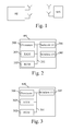
- Fig. 1 one base station BS of a wireless cellular telecommunication network and a mobile station MS are shown.
- the present invention is described when the resources of the wireless cellular telecommunication network to be used by the mobile station are allocated by a base station.
- the resources of the wireless cellular telecommunication network are the frequency spectrum used by the wireless cellular telecommunication network.
- the frequency spectrum is, for example, decomposed into groups of resource blocks and each resource block comprises a predetermined number of sub-carriers, for example twelve.
- a resource block may be composed of a single sub-carrier.
- the present invention will be disclosed with groups of resource blocks.
- the present invention is also applicable when a group of resource blocks is composed of a single resource block or is also applicable in any kind of resource allocation.
- the base station BS is a base station of a wireless cellular telecommunication network comprising plural base stations.
- the wireless cellular telecommunication network may have a more important number of mobile stations MS to communicate with the base station BS.
- the base station BS may be named a node or an access point.
- the mobile station MS may be a personal computer, a peripheral device like a set top box, or a phone.
- the base station BS the base station BS:
- the mobile station :
- Fig. 2 is a diagram representing the architecture of a base station in which the present invention is implemented.
- the base station BS has, for example, an architecture based on components connected together by a bus 201 and a processor 200 controlled by the program as disclosed in Fig. 7a or 7b .
- the base station BS may have an architecture based on dedicated integrated circuits.
- the bus 201 links the processor 200 to a read only memory ROM 202, a random access memory RAM 203, a wireless interface 205 and a network interface 206.
- the memory 203 contains registers intended to receive variables and the instructions of the program related to the algorithm as disclosed in Fig. 7a or 7b .
- the processor 200 controls the operation of the network interface 206 and of the wireless interface 205.
- the read only memory 202 contains instructions of the program related to the algorithm as disclosed in Fig 7a or 7b , which are transferred, when the base station BS is powered on, to the random access memory 203.
- the base station BS may be connected to a telecommunication network through the network interface 206.
- the network interface 206 is a DSL (Digital Subscriber Line) modem, or an ISDN (Integrated Services Digital Network) interface, etc.
- the wireless interface 205 comprises means for transferring information representative of the sub-carriers allocated to the mobile station MS.
- the wireless interface 205 comprises a decoder as disclosed in Fig. 5 .
- the wireless interface 205 may comprise an encoder as disclosed in Fig. 4 .
- Fig. 3 is a diagram representing the architecture of a mobile station in which the present invention is implemented.
- the mobile station MS has, for example, an architecture based on components connected together by a bus 301 and a processor 300 controlled by the program as disclosed in Fig. 14a or 14b .
- the mobile station MS may have an architecture based on dedicated integrated circuits.
- the bus 301 links the processor 300 to a read only memory ROM 302, a random access memory RAM 303 and a wireless interface 305.
- the memory 303 contains registers intended to receive variables and the instructions of the program related to the algorithm as disclosed in Fig. 14a or 14b .
- the processor 300 controls the operation of the wireless interface 305.
- the read only memory 302 contains instructions of the program related to the algorithm as disclosed in Fig. 14a or 14b , which are transferred, when the mobile station MS is powered on, to the random access memory 303.
- the wireless interface 305 comprises means for mapping data on sub-carriers comprised in the clusters of sub-carriers allocated to the mobile station MS .
- the wireless interface 305 comprises an encoder as disclosed in Fig. 4 .
- the wireless interface 305 may comprise a decoder as disclosed in Fig. 5 .
- Fig. 4 illustrates the architecture of the encoder having one or several transmit antennas according to a particular embodiment of the invention in frequency domain.
- Data to be transmitted are coded and organized as symbols by the coding and modulation module 40 giving a set of symbols x n . Then the signal is spread in the frequency domain by the DFT (Discrete Fourier Transform) module 41.
- the DFT module is replaced by a Fast Fourier Transform module or any other processing module.
- DFT module may not be needed.
- the symbols spread in the frequency domain are mapped on sub-carriers comprised in the allocated frequency band by a frequency mapping module 42 which maps data to be transferred on sub-carriers.
- the frequency mapping module 42 comprises zero insertion and/or frequency shaping capabilities.
- the frequency mapping module 42 maps symbols on the frequency band allocated to the mobile station MS. As the sub-carriers are not allocated in a contiguous sub-band, the frequency band is separated into several clusters. The frequency mapping module 42 maps symbols on the different clusters of the frequency band allocated to the mobile station MS.
- a first cluster comprises the sub-carriers noted n o to n 0 + T 0 -1 and a second cluster comprises the sub-carriers noted n 1 to n 1 + T 1 -1.
- the symbols outputted by the frequency mapping module 42 are transformed back in the time domain by the IDFT (Inverse Discrete Fourier Transform) module 43.
- IDFT Inverse Discrete Fourier Transform
- An optional cyclic prefix insertion module 44 can be applied before transmission through the antenna of the mobile station MS.
- Fig. 5 illustrates the architecture of the decoder of a device according to a particular embodiment of the invention.
- At least one signal 57 is received from the receive antenna.
- the synchronization module 50 synchronizes the received signal 57.
- the optional cyclic prefix removal module 51 removes the cyclic prefix if used, to the synchronized signal.
- the DFT module 52 executes a DFT on the synchronized signal on which the cyclic prefix has been removed or not.
- the DFT module is replaced by a Fast Fourier Transform module or any other processing module.
- a channel estimation module 54 will work on the signals provided by the DFT module 52.
- the output of the channel estimation module 54 commands an equalization module 53.
- the output of the equalization module 53 is processed by an inverse DFT module 55 before a classical channel decoding module 56 which treats the resulting signal.
- IDFT module 55 may not be needed. In other variants, it may be replaced with other processing modules.
- the demodulation and decoding module 56 demodulates and decodes the symbols in and outputs data.
- Fig. 6a represents an example of two clusters of groups of resource blocks allocated to a mobile station and parameters according to the present invention.
- clusters of groups of resource blocks allocated to a mobile station are not consecutive.
- the Fig. 6a discloses thirteen groups of resource blocks noted 0 to 12.
- the present invention intends to define information representing three parameters which enable a receiver like a mobile station to identify which groups of resource blocks are allocated to the mobile station, for example for uplink transmission.
- the three parameters are the identifier N of the first cluster of groups of resource blocks allocated to the mobile station MS, the number M of groups of resource blocks comprised in each cluster of groups of resource blocks allocated to the mobile station and the number L of groups of resource blocks separating the two clusters of groups of resource blocks allocated to the mobile station.
- N is equal to three
- M is equal to three
- L is equal to four.
- Fig. 6b represents an example of two clusters of groups of resource blocks allocated to a mobile station and parameters according to the present invention.
- clusters of groups of resource blocks allocated to a mobile station are not consecutive.
- the present invention intends to define information representing three parameters which enable a receiver like a mobile station to identify which groups of resource blocks are allocated to the mobile station, for example for uplink transmission.
- the three parameters are the identifier P that indentifies the first group of resource blocks separating the two clusters of groups of resource blocks allocated to the mobile station, the number M of groups of resource blocks comprised in each cluster of groups of resource blocks allocated to the mobile station and the number L of groups of resource blocks separating the two clusters of groups of resource blocks allocated to the mobile station.
- P is equal to six
- M is equal to three
- L is equal to four.
- Fig. 7a discloses an example of an algorithm executed by a base station in order to indicate the three parameters which represent the groups of resource blocks allocated to a mobile station when a first criterion is used for selecting a method indicating different values that can take information derived from two parameters which enable the mobile station to identify which groups of resource blocks are allocated to the mobile station.
- the present algorithm will be described when it is executed by the processor 200 of the base station BS.
- the present algorithm is executed each time clusters of sub-carriers are allocated to a mobile station MS handled by the base station BS.
- the processor 200 allocates groups of resource blocks to the mobile station MS.
- the allocated groups of resource blocks are allocated for example according to channel conditions and/or according to required quality of service.
- the allocated groups of resource blocks are divided into two clusters comprising the same number of groups of resource blocks.
- the processor 200 determines the three parameters that enable the mobile station MS to identify which groups of resource blocks are allocated to the mobile station MS.
- the processor 200 selects one method for determining information representing three parameters M, N and L or L, P and M among at least a first and a second methods.
- the processor 200 selects the method according to a first criterion which takes into account the value of at least two parameters.
- the processor 200 selects the first method as it will be disclosed in reference to Fig. 10a if L ⁇ M and selects the second method as it will be disclosed in reference to Fig. 10b otherwise.
- Fig. 8 represents a method for signalling two integer positive parameters when the sum between two times the first parameter and the second parameter is bounded, by means of sending one single value chosen so as to reduce the amount of information bits which are necessary to represent the two parameters.
- Fig. 8 discloses an example in which the frequency resources are divided into N RBG groups of resource blocks, wherein N RBG is equal to thirteen groups of resource blocks.
- columns represent the different values taken by the identifier N of the first group of resource blocks allocated to the mobile station MS and rows represent the number M of groups of resource blocks comprised in each cluster of groups of resource blocks allocated to the mobile station.
- the identifier N of the first group of resource blocks varies from 0 to at most N RBG minus three, i.e. ten as M and L are equal at least to one.
- N varies from null to ten.
- N varies from null to eight.
- N varies from null to six.
- N varies from null to four.
- N varies from null to two.
- N is null.
- N and M do not take any possible values. If we intend to represent N and M with respective information bits, we need four bits to represent N and three bits to represent M.
- Fig. 10a represents the first method indicating different values that can take information derived from two parameters which enable the mobile station to identify which groups of resource blocks are allocated to the mobile station.
- the first parameter is M
- the second parameter is N
- the third parameter is L
- Fig. 10a represent the different values that can take the second parameter N in the area having a bold border.
- the numbers on the right side of Fig. 10a represent the different values that can take the first parameter M in the area having a bold border.
- Fig. 10a The numbers on the top side of Fig. 10a represent the different values that can take the second parameter N in the remaining part of the Fig. 10a .
- the numbers on the left side of Fig. 10a represent the different values that can take the first parameter M in the remaining part of the Fig. 10a .
- An information derived from a first and a second parameters is given for each couple (M,N).
- the information derived from a first and a second parameters representing the couple (M,N) is noted in the cell corresponding to the intersection of the row and column of the couple (M,N).
- RIV 1 N RBG - 2 ⁇ M - 1 + N .
- RIV 1 N RBG - 2 ⁇ M max - M + 1 + N RBG - 3 - N .
- the cells comprising no information derived from a first and a second parameters are cells for which couples (M,N) are not possible.
- the information derived from a first and a second parameters RIV 1 takes thirty eight different values, it can then be represented by six bits.
- the binary value of the third parameter L is transferred in parallel. According to the invention, this method is used when L ⁇ M ⁇ M max . According to the example of Fig. 10a , M max is equal to six and thus three bits are necessary to signal the possible values of L.
- Fig. 10b represents the second method indicating different values that can take information derived from two parameters which enable the mobile station to identify which groups of resource blocks are allocated to the mobile station.
- the Fig. 10b discloses an example in which the frequency resources are divided into N RBG groups of resource blocks, wherein N RBG is equal to thirteen groups of resource blocks.
- columns represent the different values taken by the identifier P of the first group of resource blocks which is between two clusters allocated to the mobile station MS and rows represent the number L of groups of resource blocks comprised between two clusters of groups of resource blocks allocated to the mobile station.
- the first parameter is equal to L
- the second parameter is equal to P
- the third parameter is equal to M
- the identifier P varies from 1 to at most N RBG minus two and L varies from one to ten.
- Fig. 10b represent the different values that can take the second parameter P in the area having a bold border.
- Fig. 10b represent the different values that can take the first parameter L in the area having a bold border.
- Fig. 10b represent the different values that can take the second parameter P in the remaining part of the Fig. 10b .
- Fig. 10b represent the different values that can take the first parameter L in the remaining part of the Fig. 10b .
- An information derived from a first and a second parameters is given for each couple (L,P).
- the information derived from a first and a second parameters representing the couple (L,P) is noted in the cell corresponding to the intersection of the row and column of the couple (L,P).
- a cell corresponding to the intersection of the row and column of a couple (L,P) is not comprised in the area having a bold border if L ⁇ N RBG / 2 .
- RIV 2 N RBG - 2 ⁇ L - 1 + P - 1.
- RIV 2 N RBG - 2 ⁇ N RBG - L - 1 + N RGG - 2 - P .
- the information derived from a first and a second parameters RIV 2 takes sixty six different values, it can then be represented by seven bits.
- the binary value of the third parameter M value is transferred in parallel.
- M takes six values represented by three bits.
- the second method is selected when 1 ⁇ M ⁇ L , thus only for L ⁇ 2.
- the first row of the Fig. 10b can be then eliminated.
- RIV 2bis N RBG - 2 ⁇ N RBG - L - 2 + N RBG - 2 - P .
- the information derived from a first and a second parameters RIV 2bis takes fifty six different values, it can then be represented by six bits.
- the processor 200 selects the third method as disclosed in reference to Fig. 11a if L ⁇ M and selects the second method as disclosed in reference to Fig. 11b otherwise.
- Fig. 9 represents an improvement of method for arranging the value taken by two parameters when the sum between two times the first parameter and the second parameter is bounded, in order to reduce the amount of information bits which are necessary to represent the two parameters when the bound plus one is odd.
- Fig. 9 discloses an example in which the frequency resources are divided into N RBG groups of resource blocks, wherein N RBG is equal to thirteen groups of resource blocks.
- columns represent the different values taken by the identifier N of the first group of resource blocks allocated to the mobile station MS and rows represent the number M of groups of resource blocks comprised in each cluster of groups of resource blocks allocated to the mobile station.
- the identifier N of the first group of resource blocks varies from 0 to at most N RBG minus three, i.e. ten as M and L are equal at least to one.
- N varies from null to ten.
- N varies from null to eight.
- N varies from null to six.
- N varies from null to four.
- N varies from null to two.
- N is null.
- N and M do not take any possible values. If we intend to represent N and M with respective information bits, we need four bits to represent N and three bits to represent M.
- Fig. 11a represents the third method indicating different values that can take information derived from two parameters which enable the mobile station to identify which groups of resource blocks are allocated to the mobile station when the number of groups of physical resource blocks is odd.
- Fig. 11a represent the different values that can take the second parameter N in the area having a bold border.
- the numbers on the right side of Fig. 11a represent the different values that can take the first parameter M in the area having a bold border.
- Fig. 11a The numbers on the top side of Fig. 11a represent the different values that can take the second parameter N in the remaining part of the Fig. 11a .
- the numbers on the left side of Fig. 11a represent the different values that can take the first parameter M in the remaining part of the Fig. 11a .
- An information derived from a first and a second parameters is given for each couple (M,N).
- the information derived from a first and a second parameters representing the couple (M,N) is noted in the cell corresponding to the intersection of the row and column of the couple (M,N).
- RIV 3 N RBG - 1 ⁇ M - 1 + N .
- RIV 3 N RBG - 1 ⁇ M max - M + N RBG - 2 - N .
- the information derived from a first and a second parameters RIV 3 takes thirty six different values, it can then be represented by six bits.
- Fig. 11b represents the second method indicating different values that can take information derived from two parameters which enable the mobile station to identify which groups of resource blocks are allocated to the mobile station.
- Fig. 11b is identical to the Fig. 10b it will not be described anymore.
- the second method is selected when 1 ⁇ M ⁇ L , thus only for L ⁇ 2.
- the first row of the Fig. 11b can be then eliminated.
- the new information derived from a first and a second parameters RIV 2bis is calculated as already disclosed.
- the binary value of the parameter L value is transferred in parallel if the first or the third method is selected, and the binary value of the M parameter is transferred in parallel if the second method is selected.
- the smallest value between M and L is transferred in parallel. Since 2M+L is always lower than N RBG , min (M,L) ⁇ floor (N RBG / 3) the number of bits necessary for the value transferred in parallel is reduced to ceil(log2(floor(N RBG /3))) bits. One extra bit is necessary to indicate which one of the methods is to be used.
- the processor 200 applies the selected method.
- the processor 200 commands the transfer of an information bit which indicates which method among the first and second methods or which method among the third and second methods have been selected.
- the processor 200 commands the transfer of information representative of the three parameters to the mobile station, i.e. the determined information derived from a first and a second parameters and the smallest value between M and L, and the information bit which indicates the method that has been used.
- Fig. 7b discloses an example of an algorithm executed by a base station in order to indicate the three parameters which represent the groups of resource blocks allocated to a mobile station when a second criterion is used for selecting a method indicating different values that can take information derived from two parameters which enable the mobile station to identify which groups of resource blocks are allocated to the mobile station.
- the present algorithm will be described when it is executed by the processor 200 of the base station BS.
- the present algorithm is executed each time clusters of sub-carriers are allocated to a mobile station MS handled by the base station BS.
- the processor 200 allocates groups of resource blocks to the mobile station MS.
- the allocated groups of resource blocks are allocated for example according to channel conditions and/or according to required quality of service.
- the allocated groups of resource blocks are divided into two clusters comprising the same number of groups of resource blocks.
- the processor 200 determines the three parameters that enable the mobile station to identify which groups of resource blocks are allocated to the mobile station.
- the processor 200 selects one method for determining information representing three parameters: N or P, M and L among at least a first and a second methods.
- the processor 200 selects the method according to a second criterion which takes into account the value of one parameter.
- the processor 200 selects the first method as disclosed in reference to Fig. 12a if L ⁇ TH , TH being a threshold value and selects the second method as disclosed in reference to Fig. 12b otherwise.
- Fig. 12a represents the first method indicating different values that can take information derived from two parameters which enable the mobile station to identify which groups of resource blocks are allocated to the mobile station in an example wherein TH is equal to eight.
- Fig. 12a represents the information derived from two parameters which enable the mobile station to identify which groups of resource blocks are allocated to the mobile station if L ⁇ TH .
- the Fig. 12a is identical to the Fig. 10a , it will not be described anymore.
- RIV 4 N RBG - 2 ⁇ M max - M + 1 + N RBG - 3 - N .
- the cells comprising no information derived from a first and a second parameters are cells for which couples (M,N) are not possible.
- the third parameter L is transferred in parallel.
- Fig. 12b represents the second method indicating different values that can take information derived from two parameters which enable the mobile station to identify which groups of resource blocks are allocated to the mobile station in an example wherein TH is equal to eight.
- the identifier P varies from 1 to at most N RBG minus two and L varies from TH+1 to N RBG -2.
- Fig. 12b represent the different values that can take the second parameter P in the area having a bold border.
- Fig. 12b represent the different values that can take the first parameter L in the area having a bold border.
- Fig. 12b represent the different values that can take the second parameter P in the remaining part of the Fig. 12b .
- Fig. 12b represent the different values that can take the first parameter L in the remaining part of the Fig. 12b .
- An information derived from a first and a second parameters is given for each couple (L,P).
- the information derived from a first and a second parameters representing the couple (L,P) is noted in the cell corresponding to the intersection of the row and column of the couple (L,P).
- RIV 5 N RBG - 2 ⁇ N RBG - 2 - L + M TH + N RBG - 2 - P .
- the cells having no information derived from a first and a second parameters corresponds to values that the couple (L,P) cannot take.
- the third parameter M is transferred in parallel.
- TH can be equal to two, three, four, seven or eight, all these values leading to nine bits of signalling overhead.
- the processor 200 selects the third method as disclosed in reference to Fig. 13a if L ⁇ TH and selects the second method as disclosed in reference to Fig. 13b otherwise.
- Figs. 13a and 13b represent the third method and the second method indicating different values that can take information derived from two parameters which enable the mobile station to identify which groups of resource blocks are allocated to the mobile station, one method of which being selected according to the second criterion of the present invention when the number of groups of physical resource blocks is odd;
- the Figs. 13 disclose an example in which the frequency resources are divided into N RBG groups of resource blocks, wherein N RBG is equal to thirteen groups of resource blocks and wherein the threshold value is equal to eight.
- the Fig. 13a represents the information derived from two parameters which enable the mobile station to identify which groups of resource blocks are allocated to the mobile station if L ⁇ TH .
- the Fig. 13a is identical to the Fig. 11a , it will not be described anymore.
- the parameter L is transferred in parallel.
- the Fig. 13b represents the information derived from two parameters which enable the mobile station to identify which groups of resource blocks are allocated to the mobile station if L > TH .
- the identifier P of the first group of resource blocks varies from 1 to at most N RBG minus two and L varies from TH+1 to N RBG -2.
- Fig. 13b represent the different values that can take the parameter P in the area having a bold border.
- Fig. 13b represent the different values that can take the parameter L in the area having a bold border.
- Fig. 13b represent the different values that can take the parameter P in the remaining part of the Fig. 13b .
- Fig. 13b represent the different values that can take the parameter L in the remaining part of the Fig. 13b .
- the information derived from a first and a second parameters representing the couple (L,P) is noted in the cell corresponding to the intersection of the row and column of the couple (L,P).
- RIV 7 RIV 6 _max + N RBG - 2 - TH ⁇ L - TH - 1 + P .
- RIV 7 RIV 6 _max ⁇ N RBG - 2 - TH ⁇ N RBG - 1 - L + N RBG - TH - P .
- the parameter M is transferred in parallel.
- the optimum set of TH values can be defined as that set of values that minimizes: ceil ⁇ log 2 ⁇ RIV 6 _max + N RBG - 2 - TH ⁇ N RBG - 1 - TH 2 + ceil log 2 TH
- the processor 200 applies the selected method.
- the processor 200 commands the transfer of information representative of the three parameters to the mobile station.
- Fig. 14a discloses an example of an algorithm executed by a mobile station when a method is selected by the base station according to the first criterion of the present invention
- the present algorithm is executed by the processor 300 of the mobile station MS.
- the mobile station MS receives information representative of the three parameters.
- the mobile station MS receives an information bit which indicates which method has been selected by the base station.
- the mobile station MS selects the method which corresponds to the received information bit.
- the mobile station MS retrieves the three parameters from the information representative of the three parameters and the information bit.
- the processor 300 determines the parameters M and N based on the received information derived from a first and a second parameters.
- the processor 300 determines the parameters L and P based on the received information derived from a first and a second parameters.
- the value transferred separately corresponds to L.
- the value transferred separately corresponds to L.
- the mobile station MS identifies the groups of resource blocks which correspond to the three parameters.
- Fig. 14b discloses an example of an algorithm executed by a mobile station when a method is selected by the base station according to the second criterion of the present invention.
- the present algorithm is executed by the processor 300 of the mobile station MS.
- the mobile station MS receives information representative of the three parameters.
- the mobile station MS selects the method for retrieving the three parameters which corresponds to the value of the information derived from a first and a second parameters.
- each information derived from a first and a second parameters value corresponds univocally to one method.
- the threshold value of the information derived from a first and a second parameters may be stored in the RAM memory 303 of the mobile station MS.
- the mobile station MS calculates the threshold value.
- the mobile station MS retrieves the three parameters from the information derived from a first and a second parameters and from the third parameter transferred in parallel.
- L is identified as the third parameter transferred separately.
- Q floor (RIV 5 / ( N RBG ⁇ 2)
- R RIV 5 mod(N RBG ⁇ 2) of the division operation RIV / (N - 2) .
- M is identified as the third parameter transferred separately.
- L is identified as the third parameter transferred separately.
- Q floor
- R N RBG - 2 - TH
- P R .
- M is identified as the third parameter transferred separately.
- the mobile station MS identifies the groups of resource blocks which correspond to the three parameters.
- the values taken by the information representative of the two parameters may be shifted by a predetermined value.
- Supplementary bits may be added to signal either a shift or unbalanced cluster sizes.
Landscapes
- Engineering & Computer Science (AREA)
- Signal Processing (AREA)
- Computer Networks & Wireless Communication (AREA)
- Physics & Mathematics (AREA)
- Discrete Mathematics (AREA)
- General Physics & Mathematics (AREA)
- Mathematical Physics (AREA)
- Mobile Radio Communication Systems (AREA)
Abstract
- comparing the value of one of the parameters to another value,
- selecting one method among a first and a second methods indicating different values that can take information derived from the first and second parameters which enable the mobile station to identify which groups of resource blocks are allocated to the mobile station,
- determining the information from the selected method and the first and second parameters,
- transferring the determined information to the mobile station.
Description
- The present invention relates generally to a method and a device for determining information derived from a first and a second parameters among three parameters which enable a mobile station to identify which resources of a wireless telecommunication network are allocated to the mobile station.
- More precisely, the present invention is in the field of the signalling of resources of a wireless telecommunication network which are allocated to a mobile station.
- Orthogonal Frequency-Division Multiplexing (OFDM) is based upon the principle of frequency-division multiplexing (FDM) and is implemented as a digital modulation scheme. The bit stream to be transmitted is split into several parallel bit streams, typically dozens to thousands. The available frequency spectrum is divided into several sub-channels, and each low-rate bit stream is transmitted over one subchannel by modulating a sub-carrier using a standard modulation scheme, for example PSK, QAM, etc. The sub-carrier frequencies are chosen so that the modulated data streams are orthogonal to each other, meaning that cross talk between the sub-channels is eliminated.
- The primary advantage of OFDM is its ability to cope with severe channel conditions, for example, multipath and narrowband interference, without complex equalization filters. Channel equalization is simplified by using many slowly modulated narrowband signals instead of one rapidly modulated wideband signal.
- A variation called DFT spread OFDM or SC-FDMA (Single Carrier Frequency-Division Multiple Access) has been developed. In this system, each symbol to be transmitted is spread over a set of transmitted frequencies by a DFT (Discrete Fourier Transform), the resulting signal is sent over a conventional OFDMA transmission system.
- Actual implementation of coding/decoding is made either in the frequency domain or in the time domain while the implementation in the frequency domain may be preferred.
- Sometimes, the used subcarriers cannot be allocated in a contiguous sub-band, but need to be separated into several clusters. This leads to Clustered SC-FDMA, which has the advantage of a more flexible subcarrier mapping with respect to localized SC-FDMA, leading to more scheduling gain and better multi-user multiplexing.
- The present invention aims at providing a telecommunication system wherein the sub-carriers allocated to the telecommunication device are not consecutive and wherein the signalling of the allocated sub-carriers is limited.
- To that end, the present invention concerns a method for determining information derived from a first and a second parameters among three parameters which enable a mobile station to identify which resources of a wireless telecommunication network are allocated to the mobile station by a base station, the allocated resources being divided in a first cluster of at least one resource and a second cluster of at least one resource, the first and second clusters being non contiguous and comprising the same number of resources, characterised in that the method comprises the steps of:
- comparing the value of one of the parameters to another value,
- selecting one method among a first and a second methods indicating different values that can take information derived from the first and second parameters which enable the mobile station to identify which resources are allocated to the mobile station,
- determining the information from the selected method and the first and second parameters,
- transferring the determined information to the mobile station.
- The present invention concerns also a device for determining information derived from a first and a second parameters among three parameters which enable a mobile station to identify which resources of a wireless telecommunication network are allocated to the mobile station by a base station, the allocated resources being divided in a first cluster of at least one resource and a second cluster of at least one resource, the first and second clusters being non contiguous and comprising the same number of resources, characterised in that the device for determining information comprises:
- means for comparing the value of one of the parameters to another value,
- means for selecting one method among a first and a second methods indicating different values that can take information derived from the first and second parameters which enable the mobile station to identify which resources are allocated to the mobile station,
- means for determining the information from the selected method and the first and second parameters,
- means for transferring the determined information to the mobile station.
- Thus, it is possible to allocate non contiguous resources of the wireless telecommunication network to a mobile station with a limited signalling of the allocated resources.
- According to a particular feature, in the first method, the first parameter is the number of resources in each cluster, the second parameter is the index of the first resource allocated to the mobile station and the third parameter is the number of resources separating the clusters.
- According to a particular feature, in the second method, the first parameter is the number of resources separating the clusters, the second parameter is the index of the first resource separating the two clusters and the third parameter is the number of resources in each cluster.
- According to a particular feature, the parameter compared to the other value is the first parameter and the other value is the third parameter value.
- Thus, signaling is reduced.
- According to a particular feature, another information indicating the selected method is transferred.
- According to a particular feature, the parameter compared to the other value is the third parameter and the other value is a predetermined threshold.
- Thus, it is not necessary to transmit information indicating which method is selected. Signaling is simplified.
- The present invention concerns also a method for determining a first and a second parameters among three parameters which enable a mobile station to identify which resources of a wireless telecommunication network are allocated to the mobile station by a base station, the allocated resources being divided in a first cluster of at least one resource and a second cluster of at least one resource, the first and second clusters being non contiguous and comprising the same number of resources, characterised in that the method comprises the steps executed by the mobile station:
- receiving information derived from the first and second parameters,
- receiving the third parameter,
- selecting one method among a first and a second methods indicating different values that can take information derived from the first and second parameters,
- determining the first and second parameters from the information and the selected method,
- identifying the allocated resources from the first, second and third parameters.
- The present invention concerns also a device for determining a first and a second parameters among three parameters which enable a mobile station to identify which resources of a wireless telecommunication network are allocated to the mobile station by a base station, the allocated resources being divided in a first cluster of at least one resource and a second cluster of at least one resource, the first and second clusters being non contiguous and comprising the same number of resources, characterised in that the device for determining the first and the second parameters is included in the mobile station and comprises :
- means for receiving information derived from the first and second parameters,
- means for receiving the third parameter,
- means for selecting one method among a first and a second methods indicating different values that can take information derived from the first and second parameters,
- means for determining the first and second parameters from the information and the selected method,
- means for identifying the allocated resources from the first, second and third parameters.
- Thus, it is possible to allocate non contiguous resources of the wireless telecommunication network to a mobile station with a reduced signalling of the allocated resources.
- According to a particular feature, the selected method is selected from another received information indicating the selected method.
- According to still another aspect, the present invention concerns computer programs which can be directly loadable into a programmable device, comprising instructions or portions of code for implementing the steps of the methods according to the invention, when said computer programs are executed on a programmable device.
- Since the features and advantages relating to the computer programs are the same as those set out above related to the method and apparatus according to the invention, they will not be repeated here.
- The characteristics of the invention will emerge more clearly from a reading of the following description of an example embodiment, the said description being produced with reference to the accompanying drawings, among which :
-
Fig. 1 represents a wireless cellular telecommunication network in which the present invention is implemented ; -
Fig. 2 is a diagram representing the architecture of a base station in which the present invention is implemented ; -
Fig. 3 is a diagram representing the architecture of a mobile station in which the present invention is implemented ; -
Fig. 4 illustrates the architecture of the encoder comprised in a mobile station having one or several transmit antennas according to a particular embodiment of the invention in frequency domain ; -
Fig. 5 illustrates the architecture of the decoder of a base station having one or several receive antennas according to a particular embodiment of the invention ; -
Fig. 6a represents an example of two clusters of groups of resource blocks allocated to a mobile station and parameters according to the present invention ; -
Fig. 6b represents an example of two clusters of groups of resource blocks allocated to a mobile station and parameters according to the present invention ; -
Fig. 7a discloses an example of an algorithm executed by a base station in order to indicate the three parameters which represent the groups of resource blocks allocated to a mobile station when a first criterion is used for selecting a method indicating different values that can take information derived from two parameters which enable the mobile station to identify which groups of resource blocks are allocated to the mobile station; -
Fig. 7b discloses an example of an algorithm executed by a base station in order to indicate the three parameters which represent the groups of resource blocks allocated to a mobile station when a second criterion is used for selecting a method indicating different values that can take information derived from two parameters which enable the mobile station to identify which groups of resource blocks are allocated to the mobile station; -
Fig. 8 represents a method for signalling two integer positive parameters when the sum between two times the first parameter and the second parameter is bounded, by means of sending one single value chosen so as to reduce the amount of information bits which are necessary to represent the two parameters ; -
Fig. 9 represents an improvement of method for arranging the value taken by two parameters when the sum between two times the first parameter and the second parameter is bounded, in order to reduce the amount of information bits which are necessary to represent the two parameters when the bound plus one is odd; -
Figs. 10a and 10b represent a first method and a second method indicating different values that can take information derived from two parameters which enable the mobile station to identify which groups of resource blocks are allocated to the mobile station, one method of which being selected according to the first criterion of the present invention ; -
Figs. 11a and 11b represent a third method and the second method indicating different values that can take information derived from two parameters which enable the mobile station to identify which groups of resource blocks are allocated to the mobile station, one method of which being selected according to the first criterion of the present invention when the number of groups of physical resource blocks is odd; -
Figs. 12a and 12b represent the first method and the second method indicating different values that can take information derived from two parameters which enable the mobile station to identify which groups of resource blocks are allocated to the mobile station, one method of which being selected according to the second criterion of the present invention ; -
Figs. 13a and 13b represent the third method and the second method indicating different values that can take information derived from two parameters which enable the mobile station to identify which groups of resource blocks are allocated to the mobile station, one method of which being selected according to the second criterion of the present invention when the number of groups of physical resource blocks is odd; -
Fig. 14a discloses an example of an algorithm executed by a mobile station when a method is selected by the base station according to the first criterion of the present invention; -
Fig. 14b discloses an example of an algorithm executed by a mobile station when a method is selected by the base station according to the second criterion of the present invention. -
Fig. 1 represents a wireless cellular telecommunication network in which the present invention is implemented. - The present invention will be described in an example wherein the telecommunication system is a wireless cellular telecommunication system.
- The present invention is also applicable to wireless or wired telecommunication systems like Local Area Networks.
- In that case, the base station and mobile station are emitters and/or receivers.
- In
Fig. 1 , one base station BS of a wireless cellular telecommunication network and a mobile station MS are shown. - The present invention is described when the resources of the wireless cellular telecommunication network to be used by the mobile station are allocated by a base station.
- The resources of the wireless cellular telecommunication network are the frequency spectrum used by the wireless cellular telecommunication network. The frequency spectrum is, for example, decomposed into groups of resource blocks and each resource block comprises a predetermined number of sub-carriers, for example twelve.
- It has to be noted here that in a variant a resource block may be composed of a single sub-carrier.
- The present invention will be disclosed with groups of resource blocks. The present invention is also applicable when a group of resource blocks is composed of a single resource block or is also applicable in any kind of resource allocation.
- The base station BS is a base station of a wireless cellular telecommunication network comprising plural base stations.
- Only one mobile station MS is shown for the sake of clarity but the wireless cellular telecommunication network may have a more important number of mobile stations MS to communicate with the base station BS.
- The base station BS may be named a node or an access point.
- The mobile station MS may be a personal computer, a peripheral device like a set top box, or a phone.
- According to the invention, the base station BS:
- compares one of the parameters value to another value,
- selects one method among a first and a second methods indicating different values that can take information derived from the first and second parameters which enable the mobile station to identify which groups of resource blocks are allocated to the mobile station,
- determines the information from the selected method and the first and second parameters,
- transfers the determined information to the mobile station.
- According to the invention, the mobile station :
- receives information derived from the first and second parameters,
- receives the third parameter,
- selects one method among a first and a second methods indicating different values that can take information derived from the first and second parameters,
- determines the first and second parameters from the information and the selected method,
- identifies the allocated resources from the first, second and third parameters.
-
Fig. 2 is a diagram representing the architecture of a base station in which the present invention is implemented. - The base station BS has, for example, an architecture based on components connected together by a
bus 201 and aprocessor 200 controlled by the program as disclosed inFig. 7a or 7b . - It has to be noted here that the base station BS may have an architecture based on dedicated integrated circuits.
- The
bus 201 links theprocessor 200 to a read onlymemory ROM 202, a randomaccess memory RAM 203, awireless interface 205 and anetwork interface 206. - The
memory 203 contains registers intended to receive variables and the instructions of the program related to the algorithm as disclosed inFig. 7a or 7b . - The
processor 200 controls the operation of thenetwork interface 206 and of thewireless interface 205. - The read only
memory 202 contains instructions of the program related to the algorithm as disclosed inFig 7a or 7b , which are transferred, when the base station BS is powered on, to therandom access memory 203. - The base station BS may be connected to a telecommunication network through the
network interface 206. For example, thenetwork interface 206 is a DSL (Digital Subscriber Line) modem, or an ISDN (Integrated Services Digital Network) interface, etc. - The
wireless interface 205 comprises means for transferring information representative of the sub-carriers allocated to the mobile station MS. - The
wireless interface 205 comprises a decoder as disclosed inFig. 5 . Thewireless interface 205 may comprise an encoder as disclosed inFig. 4 . -
Fig. 3 is a diagram representing the architecture of a mobile station in which the present invention is implemented. - The mobile station MS has, for example, an architecture based on components connected together by a
bus 301 and aprocessor 300 controlled by the program as disclosed inFig. 14a or 14b . - It has to be noted here that the mobile station MS may have an architecture based on dedicated integrated circuits.
- The
bus 301 links theprocessor 300 to a read onlymemory ROM 302, a randomaccess memory RAM 303 and awireless interface 305. - The
memory 303 contains registers intended to receive variables and the instructions of the program related to the algorithm as disclosed inFig. 14a or 14b . - The
processor 300 controls the operation of thewireless interface 305. - The read only
memory 302 contains instructions of the program related to the algorithm as disclosed inFig. 14a or 14b , which are transferred, when the mobile station MS is powered on, to therandom access memory 303. - The
wireless interface 305 comprises means for mapping data on sub-carriers comprised in the clusters of sub-carriers allocated to the mobile station MS . - The
wireless interface 305 comprises an encoder as disclosed inFig. 4 . Thewireless interface 305 may comprise a decoder as disclosed inFig. 5 . -
Fig. 4 illustrates the architecture of the encoder having one or several transmit antennas according to a particular embodiment of the invention in frequency domain. - Data to be transmitted are coded and organized as symbols by the coding and
modulation module 40 giving a set of symbols xn . Then the signal is spread in the frequency domain by the DFT (Discrete Fourier Transform)module 41. In a variant, the DFT module is replaced by a Fast Fourier Transform module or any other processing module. - In case of OFDMA, DFT module may not be needed.
- The symbols spread in the frequency domain are mapped on sub-carriers comprised in the allocated frequency band by a
frequency mapping module 42 which maps data to be transferred on sub-carriers. Thefrequency mapping module 42 comprises zero insertion and/or frequency shaping capabilities. - The
frequency mapping module 42 maps symbols on the frequency band allocated to the mobile station MS. As the sub-carriers are not allocated in a contiguous sub-band, the frequency band is separated into several clusters. Thefrequency mapping module 42 maps symbols on the different clusters of the frequency band allocated to the mobile station MS. - In
Fig. 4 , thefrequency mapping module 42 shows an example wherein T=T 0+ T 1 symbols are mapped on T sub-carriers of two clusters. A first cluster comprises the sub-carriers noted no to n 0+T 0-1 and a second cluster comprises the sub-carriers noted n 1 to n 1+T 1-1. - The symbols outputted by the
frequency mapping module 42 are transformed back in the time domain by the IDFT (Inverse Discrete Fourier Transform)module 43. - An optional cyclic
prefix insertion module 44 can be applied before transmission through the antenna of the mobile station MS. -
Fig. 5 illustrates the architecture of the decoder of a device according to a particular embodiment of the invention. - At least one
signal 57 is received from the receive antenna. Thesynchronization module 50 synchronizes the receivedsignal 57. - The optional cyclic
prefix removal module 51 removes the cyclic prefix if used, to the synchronized signal. - The
DFT module 52 executes a DFT on the synchronized signal on which the cyclic prefix has been removed or not. In a variant, the DFT module is replaced by a Fast Fourier Transform module or any other processing module. - A
channel estimation module 54 will work on the signals provided by theDFT module 52. The output of thechannel estimation module 54 commands anequalization module 53. The output of theequalization module 53 is processed by aninverse DFT module 55 before a classicalchannel decoding module 56 which treats the resulting signal. - In case of OFDMA,
IDFT module 55 may not be needed. In other variants, it may be replaced with other processing modules. - The demodulation and
decoding module 56 demodulates and decodes the symbols in and outputs data. -
Fig. 6a represents an example of two clusters of groups of resource blocks allocated to a mobile station and parameters according to the present invention. - According to the invention, clusters of groups of resource blocks allocated to a mobile station are not consecutive.
- In the example of
Fig. 6a , two clusters of groups of resource blocks are allocated to one mobile station MS. - The
Fig. 6a discloses thirteen groups of resource blocks noted 0 to 12. - In order to limit both the Peak to Average Power Ratio PAPR increase and the signalling overhead, the allocation of two clusters of equal size is assumed.
- The present invention intends to define information representing three parameters which enable a receiver like a mobile station to identify which groups of resource blocks are allocated to the mobile station, for example for uplink transmission.
- The three parameters are the identifier N of the first cluster of groups of resource blocks allocated to the mobile station MS, the number M of groups of resource blocks comprised in each cluster of groups of resource blocks allocated to the mobile station and the number L of groups of resource blocks separating the two clusters of groups of resource blocks allocated to the mobile station. According to the example of
Fig. 6a , N is equal to three, M is equal to three and L is equal to four. -
Fig. 6b represents an example of two clusters of groups of resource blocks allocated to a mobile station and parameters according to the present invention. - According to the invention, clusters of groups of resource blocks allocated to a mobile station are not consecutive.
- In the example of
Fig. 6b , the same clusters of groups of resource blocks are allocated to one mobile station MS as the ones ofFig. 6a . - The present invention intends to define information representing three parameters which enable a receiver like a mobile station to identify which groups of resource blocks are allocated to the mobile station, for example for uplink transmission.
- The three parameters are the identifier P that indentifies the first group of resource blocks separating the two clusters of groups of resource blocks allocated to the mobile station, the number M of groups of resource blocks comprised in each cluster of groups of resource blocks allocated to the mobile station and the number L of groups of resource blocks separating the two clusters of groups of resource blocks allocated to the mobile station. According to the example of
Fig. 6b , P is equal to six, M is equal to three and L is equal to four. -
Fig. 7a discloses an example of an algorithm executed by a base station in order to indicate the three parameters which represent the groups of resource blocks allocated to a mobile station when a first criterion is used for selecting a method indicating different values that can take information derived from two parameters which enable the mobile station to identify which groups of resource blocks are allocated to the mobile station. - For example, the present algorithm will be described when it is executed by the
processor 200 of the base station BS. - The present algorithm is executed each time clusters of sub-carriers are allocated to a mobile station MS handled by the base station BS.
- At step S700, the
processor 200 allocates groups of resource blocks to the mobile station MS. The allocated groups of resource blocks are allocated for example according to channel conditions and/or according to required quality of service. The allocated groups of resource blocks are divided into two clusters comprising the same number of groups of resource blocks. - At next step S701, the
processor 200 determines the three parameters that enable the mobile station MS to identify which groups of resource blocks are allocated to the mobile station MS. - At next step S702, the
processor 200 selects one method for determining information representing three parameters M, N and L or L, P and M among at least a first and a second methods. - According to a first mode of realization of the present invention, the
processor 200 selects the method according to a first criterion which takes into account the value of at least two parameters. - For example, the
processor 200 selects the first method as it will be disclosed in reference toFig. 10a if L ≤ M and selects the second method as it will be disclosed in reference toFig. 10b otherwise. -
Fig. 8 represents a method for signalling two integer positive parameters when the sum between two times the first parameter and the second parameter is bounded, by means of sending one single value chosen so as to reduce the amount of information bits which are necessary to represent the two parameters. -
Fig. 8 discloses an example in which the frequency resources are divided into NRBG groups of resource blocks, wherein NRBG is equal to thirteen groups of resource blocks. - In
Fig. 8 , columns represent the different values taken by the identifier N of the first group of resource blocks allocated to the mobile station MS and rows represent the number M of groups of resource blocks comprised in each cluster of groups of resource blocks allocated to the mobile station. - The identifier N of the first group of resource blocks varies from 0 to at most NRBG minus three, i.e. ten as M and L are equal at least to one.
- If M is equal to one, N varies from null to ten.
- If M is equal to two, N varies from null to eight.
- If M is equal to three, N varies from null to six.
- If M is equal to four, N varies from null to four.
- If M is equal to five, N varies from null to two.
- If M is equal to six, N is null.
- As it can be seen in
Fig. 8 , N and M do not take any possible values. If we intend to represent N and M with respective information bits, we need four bits to represent N and three bits to represent M. - In order to reduce the number of information bits, the rows of M=5 and 6 of the area P2 and shifted to the rows of M=2 and 3 of the area P1.
- As a result, we obtain the arrangement as disclosed in
Fig. 10a . -
Fig. 10a represents the first method indicating different values that can take information derived from two parameters which enable the mobile station to identify which groups of resource blocks are allocated to the mobile station. - In the first method, the first parameter is M, the second parameter is N and the third parameter is L.
- The numbers on the lower side of
Fig. 10a represent the different values that can take the second parameter N in the area having a bold border. - The numbers on the right side of
Fig. 10a represent the different values that can take the first parameter M in the area having a bold border. - The numbers on the top side of
Fig. 10a represent the different values that can take the second parameter N in the remaining part of theFig. 10a . - The numbers on the left side of
Fig. 10a represent the different values that can take the first parameter M in the remaining part of theFig. 10a . - An information derived from a first and a second parameters is given for each couple (M,N). The information derived from a first and a second parameters representing the couple (M,N) is noted in the cell corresponding to the intersection of the row and column of the couple (M,N).
- A cell corresponding to the intersection of the row and column of a couple (M,N) is not comprised in the area having a bold border if

- If the cell corresponding to the intersection of the row and column of a couple (M,N) is not comprised in the area having a bold border, the information derived from a first and a second parameters RIV1 is calculated according to the following formula:

- If the cell corresponding to the intersection of the row and column of a couple (M,N) is comprised in the area having a bold border, the information derived from a first and a second parameters RIV1 is calculated according to the following formula:

- The cells comprising no information derived from a first and a second parameters are cells for which couples (M,N) are not possible.
- The information derived from a first and a second parameters RIV1 takes thirty eight different values, it can then be represented by six bits.
- It has to be noted here that the binary value of the third parameter L is transferred in parallel. According to the invention, this method is used when L ≤M ≤ M max . According to the example of
Fig. 10a , Mmax is equal to six and thus three bits are necessary to signal the possible values of L. -
Fig. 10b represents the second method indicating different values that can take information derived from two parameters which enable the mobile station to identify which groups of resource blocks are allocated to the mobile station. - The
Fig. 10b discloses an example in which the frequency resources are divided into NRBG groups of resource blocks, wherein NRBG is equal to thirteen groups of resource blocks. - In
Fig. 10b , columns represent the different values taken by the identifier P of the first group of resource blocks which is between two clusters allocated to the mobile station MS and rows represent the number L of groups of resource blocks comprised between two clusters of groups of resource blocks allocated to the mobile station. - In the second method, the first parameter is equal to L, the second parameter is equal to P and the third parameter is equal to M.
- The identifier P varies from 1 to at most NRBG minus two and L varies from one to ten.
- The numbers on the lower side of
Fig. 10b represent the different values that can take the second parameter P in the area having a bold border. - The numbers on the right side of
Fig. 10b represent the different values that can take the first parameter L in the area having a bold border. - The numbers on the top side of
Fig. 10b represent the different values that can take the second parameter P in the remaining part of theFig. 10b . - The numbers on the left side of
Fig. 10b represent the different values that can take the first parameter L in the remaining part of theFig. 10b . - An information derived from a first and a second parameters is given for each couple (L,P). The information derived from a first and a second parameters representing the couple (L,P) is noted in the cell corresponding to the intersection of the row and column of the couple (L,P).
- A cell corresponding to the intersection of the row and column of a couple (L,P) is not comprised in the area having a bold border if L ≤ NRBG / 2 .
- If the cell corresponding to the intersection of the row and column of a couple (L,P) is not comprised in the area having a bold border, the information derived from a first and a second parameters RIV2 is calculated according to the following formula:

- If the cell corresponding to the intersection of the row and column of a couple (L,P) is comprised in the area having a bold border, the information derived from a first and a second parameters RIV2 is calculated according to the following formula:

- The information derived from a first and a second parameters RIV2 takes sixty six different values, it can then be represented by seven bits.
- The binary value of the third parameter M value is transferred in parallel. M takes six values represented by three bits.
- The smallest value between M and L is transferred in parallel. Since 2M+L is always lower than NRBG, min (M, L)≤floor(NRGB/3), ceil(log2(floor(NRBG/3))) bits are needed for the value transferred in parallel. One extra bit is necessary to indicate which one of the methods is to be used.
- It has to the noted here that the second method is selected when 1 ≤ M < L , thus only for L ≥ 2. The first row of the
Fig. 10b can be then eliminated. According to that particular mode of realization, if the cell corresponding to the intersection of the row and column of a couple (L,P) is not comprised in the area having a bold border, the new information derived from a first and a second parameters RIV2bis is calculated according to the following formula:
- If the cell corresponding to the intersection of the row and column of a couple (L,P) is comprised in the area having a bold border, the information derived from a first and a second parameters RIV2bis is calculated according to the following formula:

- The information derived from a first and a second parameters RIV2bis takes fifty six different values, it can then be represented by six bits.
- According to another example, if the number of groups of blocks of resource elements is odd, the
processor 200 selects the third method as disclosed in reference toFig. 11a if L ≤ M and selects the second method as disclosed in reference toFig. 11b otherwise. -
Fig. 9 represents an improvement of method for arranging the value taken by two parameters when the sum between two times the first parameter and the second parameter is bounded, in order to reduce the amount of information bits which are necessary to represent the two parameters when the bound plus one is odd. -
Fig. 9 discloses an example in which the frequency resources are divided into NRBG groups of resource blocks, wherein NRBG is equal to thirteen groups of resource blocks. - In
Fig. 9 , columns represent the different values taken by the identifier N of the first group of resource blocks allocated to the mobile station MS and rows represent the number M of groups of resource blocks comprised in each cluster of groups of resource blocks allocated to the mobile station. - The identifier N of the first group of resource blocks varies from 0 to at most NRBG minus three, i.e. ten as M and L are equal at least to one.
- If M is equal to one, N varies from null to ten.
- If M is equal to two, N varies from null to eight.
- If M is equal to three, N varies from null to six.
- If M is equal to four, N varies from null to four.
- If M is equal to five, N varies from null to two.
- If M is equal to six, N is null.
- As it can be seen in
Fig. 9 , N and M do not take any possible values. If we intend to represent N and M with respective information bits, we need four bits to represent N and three bits to represent M. - In order to reduce the number of information bits, the rows of M=4 to 6 of the area P2' are shifted to the rows of M=1 to 3 of the area P1'.
- As a result, we obtain the arrangement as disclosed in
Fig. 11 a. -
Fig. 11a represents the third method indicating different values that can take information derived from two parameters which enable the mobile station to identify which groups of resource blocks are allocated to the mobile station when the number of groups of physical resource blocks is odd. - The numbers on the lower side of
Fig. 11a represent the different values that can take the second parameter N in the area having a bold border. - The numbers on the right side of
Fig. 11a represent the different values that can take the first parameter M in the area having a bold border. - The numbers on the top side of
Fig. 11a represent the different values that can take the second parameter N in the remaining part of theFig. 11a . - The numbers on the left side of
Fig. 11a represent the different values that can take the first parameter M in the remaining part of theFig. 11a . - An information derived from a first and a second parameters is given for each couple (M,N). The information derived from a first and a second parameters representing the couple (M,N) is noted in the cell corresponding to the intersection of the row and column of the couple (M,N).
- A cell corresponding to the intersection of the row and column of a couple (M,N) is not comprised in the area having a bold border if M ≤ M'TH =
ceil 
- If the cell corresponding to the intersection of the row and column of a couple (M,N) is not comprised in the area having a bold border, the information derived from a first and a second parameters RIV3 is calculated according to the following formula:

- If the cell corresponding to the intersection of the row and column of a couple (M,N) is comprised in the area having a bold border, the information derived from a first and a second parameters RIV3 is calculated according to the following formula:

- The information derived from a first and a second parameters RIV3 takes thirty six different values, it can then be represented by six bits.
-
Fig. 11b represents the second method indicating different values that can take information derived from two parameters which enable the mobile station to identify which groups of resource blocks are allocated to the mobile station. -
Fig. 11b is identical to theFig. 10b it will not be described anymore. - It has to the noted here that, as already disclosed, the second method is selected when 1≤ M < L , thus only for L ≥ 2. The first row of the
Fig. 11b can be then eliminated. - According to that particular mode of realization, if the cell corresponding to the intersection of the row and column of a couple (L,P) is not comprised in the area having a bold border, the new information derived from a first and a second parameters RIV2bis is calculated as already disclosed.
- It has to be noted that in above mentioned examples, the binary value of the parameter L value is transferred in parallel if the first or the third method is selected, and the binary value of the M parameter is transferred in parallel if the second method is selected. Thus, the smallest value between M and L is transferred in parallel. Since 2M+L is always lower than NRBG, min (M,L)≤ floor (NRBG / 3) the number of bits necessary for the value transferred in parallel is reduced to ceil(log2(floor(NRBG/3))) bits. One extra bit is necessary to indicate which one of the methods is to be used.
- At next step S703, the
processor 200 applies the selected method. - At next step S704, the
processor 200 commands the transfer of an information bit which indicates which method among the first and second methods or which method among the third and second methods have been selected. - At next step S705, the
processor 200 commands the transfer of information representative of the three parameters to the mobile station, i.e. the determined information derived from a first and a second parameters and the smallest value between M and L, and the information bit which indicates the method that has been used. -
Fig. 7b discloses an example of an algorithm executed by a base station in order to indicate the three parameters which represent the groups of resource blocks allocated to a mobile station when a second criterion is used for selecting a method indicating different values that can take information derived from two parameters which enable the mobile station to identify which groups of resource blocks are allocated to the mobile station. - For example, the present algorithm will be described when it is executed by the
processor 200 of the base station BS. - The present algorithm is executed each time clusters of sub-carriers are allocated to a mobile station MS handled by the base station BS.
- At step S750, the
processor 200 allocates groups of resource blocks to the mobile station MS. The allocated groups of resource blocks are allocated for example according to channel conditions and/or according to required quality of service. The allocated groups of resource blocks are divided into two clusters comprising the same number of groups of resource blocks. - At next step S751, the
processor 200 determines the three parameters that enable the mobile station to identify which groups of resource blocks are allocated to the mobile station. - At next step S752, the
processor 200 selects one method for determining information representing three parameters: N or P, M and L among at least a first and a second methods. - According to a second mode of realization of the present invention, the
processor 200 selects the method according to a second criterion which takes into account the value of one parameter. - For example, the
processor 200 selects the first method as disclosed in reference toFig. 12a if L ≤ TH , TH being a threshold value and selects the second method as disclosed in reference toFig. 12b otherwise. -
Fig. 12a represents the first method indicating different values that can take information derived from two parameters which enable the mobile station to identify which groups of resource blocks are allocated to the mobile station in an example wherein TH is equal to eight. -
Fig. 12a represents the information derived from two parameters which enable the mobile station to identify which groups of resource blocks are allocated to the mobile station if L ≤ TH . - The
Fig. 12a is identical to theFig. 10a , it will not be described anymore. - If the cell corresponding to the intersection of the row and column of a couple (M,N) is not comprised in the area having a bold border, the information derived from a first and a second parameters RIV4 which is identical to the information derived from a first and a second parameters RIV1 is calculated according to the following formula:

- If the cell corresponding to the intersection of the row and column of a couple (M,N) is comprised in the area having a bold border, the information derived from a first and a second parameters RIV4 is calculated according to the following formula:

- The cells comprising no information derived from a first and a second parameters are cells for which couples (M,N) are not possible.
- The information derived from a first and a second parameters RIV4 values up to thirty seven, it can then be represented by six bits.
- If the method disclosed in
Fig. 12a is selected, the third parameter L is transferred in parallel. -
Fig. 12b represents the second method indicating different values that can take information derived from two parameters which enable the mobile station to identify which groups of resource blocks are allocated to the mobile station in an example wherein TH is equal to eight. - The identifier P varies from 1 to at most NRBG minus two and L varies from TH+1 to NRBG-2.
- The numbers on the lower side of
Fig. 12b represent the different values that can take the second parameter P in the area having a bold border. - The numbers on the right side of
Fig. 12b represent the different values that can take the first parameter L in the area having a bold border. - The numbers on the top side of
Fig. 12b represent the different values that can take the second parameter P in the remaining part of theFig. 12b . - The numbers on the left side of
Fig. 12b represent the different values that can take the first parameter L in the remaining part of theFig. 12b . - An information derived from a first and a second parameters is given for each couple (L,P). The information derived from a first and a second parameters representing the couple (L,P) is noted in the cell corresponding to the intersection of the row and column of the couple (L,P).
- A cell corresponding to the intersection of the row and column of a couple (L,P) is not comprised in the area having a bold border if

- If the cell corresponding to the intersection of the row and column of a couple (L,P) is not comprised in the area having a bold border, the information derived from a first and a second parameters RIV5 is calculated according to the following formula:

where
- If the cell corresponding to the intersection of the row and column of a couple (L,P) is comprised in the area having a bold border, the information derived from a first and a second parameters RIV5 is calculated according to the following formula:

- The cells having no information derived from a first and a second parameters corresponds to values that the couple (L,P) cannot take.
- If the method disclosed in
Fig. 12b is selected, the third parameter M is transferred in parallel. - At most six bits are thus necessary to signal the values of information derived from a first and a second parameters positive and inferior to fifty six. Overall, nine bits are necessary. High TH values may reduce the number of bits representative of the RIV5 but would increase the number of bits representative of L when L ≤ LTH Several optimum values for TH can be found. The optimum set of TH values can be defined as that set of values that minimizes:

, where:
- TH can be equal to two, three, four, seven or eight, all these values leading to nine bits of signalling overhead.
- In another example, if NRBG is odd, the
processor 200 selects the third method as disclosed in reference toFig. 13a if L ≤ TH and selects the second method as disclosed in reference toFig. 13b otherwise. -
Figs. 13a and 13b represent the third method and the second method indicating different values that can take information derived from two parameters which enable the mobile station to identify which groups of resource blocks are allocated to the mobile station, one method of which being selected according to the second criterion of the present invention when the number of groups of physical resource blocks is odd; - The
Figs. 13 disclose an example in which the frequency resources are divided into NRBG groups of resource blocks, wherein NRBG is equal to thirteen groups of resource blocks and wherein the threshold value is equal to eight. - The
Fig. 13a represents the information derived from two parameters which enable the mobile station to identify which groups of resource blocks are allocated to the mobile station if L ≤ TH . - The
Fig. 13a is identical to theFig. 11a , it will not be described anymore. - If the cell corresponding to the intersection of the row and column of a couple (M,N) is not comprised in the area having a bold border, the information derived from a first and a second parameters RIV6 which is identical to the information derived from a first and a second parameters RIV3 is calculated according to the following formula:

- If the cell corresponding to the intersection of the row and column of a couple (L,P) is comprised in the area having a bold border, the information derived from a first and a second parameters RIV6 is calculated according to the following formula:

- If the method disclosed in
Fig. 13a is selected, the parameter L is transferred in parallel. - The
Fig. 13b represents the information derived from two parameters which enable the mobile station to identify which groups of resource blocks are allocated to the mobile station if L > TH . - The identifier P of the first group of resource blocks varies from 1 to at most NRBG minus two and L varies from TH+1 to NRBG-2.
- The numbers on the lower side of
Fig. 13b represent the different values that can take the parameter P in the area having a bold border. - The numbers on the right side of
Fig. 13b represent the different values that can take the parameter L in the area having a bold border. - The numbers on the top side of
Fig. 13b represent the different values that can take the parameter P in the remaining part of theFig. 13b . - The numbers on the left side of
Fig. 13b represent the different values that can take the parameter L in the remaining part of theFig. 13b . - An information derived from a first and a second parameters in given for each couple (L,P). The information derived from a first and a second parameters representing the couple (L,P) is noted in the cell corresponding to the intersection of the row and column of the couple (L,P).
- A cell corresponding to the intersection of the row and column of a couple (L,P) is not comprised in the area having a bold border if

- If the cell corresponding to the intersection of the row and column of a couple (L,P) is not comprised in the area having a bold border, the information derived from a first and a second parameters RIV7 is calculated according to the following formula:

- If the cell corresponding to the intersection of the row and column of a couple (L,P) is comprised in the area having a bold border, the information derived from a first and a second parameters RIV7 is calculated according to the following formula:

- If the method disclosed in
Fig. 13b is selected, the parameter M is transferred in parallel. - The optimum set of TH values can be defined as that set of values that minimizes:

- RIV6_max is the total number of possible pairs (M,N), which is:

- It has to be noted here that the information derived from two parameters as disclosed in reference to
Fig. 13b may be used in combination with the information derived from two parameters as disclosed in reference toFig. 12a . - At next step S753, the
processor 200 applies the selected method. - At next step S754, the
processor 200 commands the transfer of information representative of the three parameters to the mobile station. - It has to be noted here that as the information derived from a first and a second parameters values for the first or third method are different from the information derived from a first and a second parameters for the second method, it is not necessary to inform the mobile station which method is selected.
-
Fig. 14a discloses an example of an algorithm executed by a mobile station when a method is selected by the base station according to the first criterion of the present invention ; - More precisely, the present algorithm is executed by the
processor 300 of the mobile station MS. - At step S1400, the mobile station MS receives information representative of the three parameters.
- At step S1401, the mobile station MS receives an information bit which indicates which method has been selected by the base station.
- At next step S1402, the mobile station MS selects the method which corresponds to the received information bit.
- At next step S 1403, the mobile station MS retrieves the three parameters from the information representative of the three parameters and the information bit.
- If the information bit shows that the information derived from a first and a second parameters has been calculated according to the first method, the
processor 300 determines the parameters M and N based on the received information derived from a first and a second parameters. The value transferred separately corresponds to L. - If the information bit shows that the information derived from a first and a second parameters has been calculated according to the second method, the
processor 300 determines the parameters L and P based on the received information derived from a first and a second parameters. The value transferred separately corresponds to M. - If the information derived from a first and a second parameters was calculated with the formula RIV1, the
processor 300 determines the parameters M and N by calculating the quotient Q = floor(RIV1 / (NRBG ― 2)) and the remainder R = RIV1 mod(N - 2) of the division operation RlV1 / (NRBG ― 2), where Amod(B) denotes the A modulo B function.

- The value transferred separately corresponds to L.
- If the information derived from a first and a second parameters has been calculated according to the formula RIV2, the
processor 300 determines the parameters L and P by calculating the quotient Q = floor(RIV2 / (NRBG ― 2)) and the remainder R = RlV2 mod(NRBG ― 2) of the division operation RIV2 / (NRBG ―2).

- The value transferred separately corresponds to M.
- If the information derived from a first and a second parameters has been calculated according to the formula RIV3, the
processor 300 determines the parameters M and N by calculating the quotient Q = floor(RIV3 / (NRBG ―1)) and the remainder R = RIV3 mod(NRBG ― 1) of the division operation RIV3 / (NRBG ―1) , where mod(x) denotes the modulo of x.

- The value transferred separately corresponds to L.
- At next step S1404, the mobile station MS identifies the groups of resource blocks which correspond to the three parameters.
-
Fig. 14b discloses an example of an algorithm executed by a mobile station when a method is selected by the base station according to the second criterion of the present invention. - More precisely, the present algorithm is executed by the
processor 300 of the mobile station MS. - At step S1450, the mobile station MS receives information representative of the three parameters.
- At next step S1451, the mobile station MS selects the method for retrieving the three parameters which corresponds to the value of the information derived from a first and a second parameters.
- As shown in
Figs. 12 and13 , each information derived from a first and a second parameters value corresponds univocally to one method. - The threshold value of the information derived from a first and a second parameters may be stored in the
RAM memory 303 of the mobile station MS. In a variant, the mobile station MS calculates the threshold value. - At next step S 1452, the mobile station MS retrieves the three parameters from the information derived from a first and a second parameters and from the third parameter transferred in parallel.
- If the information derived from a first and a second parameters has been calculated according to the formula RIV4, the
processor 300 determines the parameters M and N by calculating the quotient Q = floor(RIV4 / (NRBG ― 2)) and the remainder R = RIV4 mod(NRBG -2) of the division operation RIV / (N - 2), where mod(x) denotes the modulo of x. 4 RBG

- L is identified as the third parameter transferred separately.
- If the information derived from a first and a second parameters has been calculated according to the formula RIV5, the
processor 300 determines the parameters L and P by calculating the quotient Q = floor (RIV5 / (NRBG ― 2)) and the remainder R = RIV5 mod(NRBG ― 2) of the division operation RIV / (N - 2) .

- M is identified as the third parameter transferred separately.
- If the information derived from a first and a second parameters has been calculated according to the formula RIV6, the
processor 300 determines the parameters M and N by calculating the quotient Q = floor(RIV / (N -1)) and 6 RBG the remainder R = RlV6 mod(NRBG -1) of the division operation RIV / (NRBG -1) , where mod(x) denotes the modulo of x. 6

- L is identified as the third parameter transferred separately.
- If the information derived from a first and a second parameters has been calculated according to the formula RIV7, the
processor 300 determines the parameters L and P by calculating the quotient Q = floor ( (R1V7 - RIV6_max) /(NRBG -2 - TH)) and the remainder R = ((RIV7 - RIV6_max)mod(NREG-2-TH)) .

- M is identified as the third parameter transferred separately.
- At next step S1453, the mobile station MS identifies the groups of resource blocks which correspond to the three parameters.
- Naturally, many modifications can be made to the embodiments of the invention described above without departing from the scope of the present invention.
- For example, the values taken by the information representative of the two parameters may be shifted by a predetermined value.
- Supplementary bits may be added to signal either a shift or unbalanced cluster sizes.
- All the concepts applied here at group of resource blocks level can be transposed to resource blocks or subcarrier level for other types of applications.
Claims (15)
- Method for determining information derived from a first and a second parameters among three parameters which enable a mobile station to identify which resources of a wireless telecommunication network are allocated to the mobile station by a base station, the allocated resources being divided in a first cluster of at least one resource and a second cluster of at least one resource, the first and second clusters being non contiguous and comprising the same number of resources, characterised in that the method comprises the steps of:- comparing the value of one of the parameters to another value,- selecting one method among a first and a second methods indicating different values that can take information derived from the first and second parameters which enable the mobile station to identify which resources are allocated to the mobile station,- determining the information from the selected method and the first and second parameters,- transferring the determined information to the mobile station.
- Method according to claim 1, characterised in that in the first method, the first parameter is the number of resources in each cluster, the second parameter is the index of the first resource allocated to the mobile station and the third parameter is the number of resources separating the clusters.
- Method according to claim 1 or 2, characterised in that, in the second method, the first parameter is the number of resources separating the clusters, the second parameter is the index of the first resource separating the two clusters and the third parameter is the number of resources in each cluster.
- Method according to any of the claims 1 to 3, characterised in that the parameter compared to the other value is the first parameter and the other value is the third parameter value.
- Method according to claim 4, characterised in that the method comprises further step of transferring another information indicating the selected method.
- Method according to claim 1, characterised in that the parameter compared to the other value is the third parameter and the other value is a predetermined threshold.
- Method according to claim 5 or 6, characterised in that the method comprises further step of transferring information representative of the third parameter.
- Method for determining a first and a second parameters among three parameters which enable a mobile station to identify which resources of a wireless telecommunication network are allocated to the mobile station by a base station, the allocated resources being divided in a first cluster of at least one resource and a second cluster of at least one resource, the first and second clusters being non contiguous and comprising the same number of resources, characterised in that the method comprising the steps executed by the mobile station :- receiving information derived from the first and second parameters,- receiving the third parameter,- selecting one method among a first and a second methods indicating different values that can take information derived from the first and second parameters,- determining the first and second parameters from the information and the selected method,- identifying the allocated resources from the first, second and third parameters.
- Method according to claim 8, characterised in that in the first method, the first parameter is the number of resources in each cluster, the second parameter is the index of the first resource allocated to the mobile station and the third parameter is the number of resources separating the clusters.
- Method according to claim 8 or 9, characterised in that, in the second method, the first parameter is the number of resources separating the clusters, the second parameter is the index of the first resource separating the two clusters and the third parameter is the number of resources in each cluster.
- Method according to claim 10, characterised in that the selected method is selected from another received information indicating the selected method.
- Device for determining information derived from a first and a second parameters among three parameters which enable a mobile station to identify which resources of a wireless telecommunication network are allocated to the mobile station by a base station, the allocated resources being divided in a first cluster of at least one resource and a second cluster of at least one resource, the first and second clusters being non contiguous and comprising the same number of resources, characterised in that the device for determining information comprises:- means for comparing the value of one of the parameters to another value,- means for selecting one method among a first and a second methods indicating different values that can take information derived from the first and second parameters which enable the mobile station to identify which resources are allocated to the mobile station,- means for determining the information from the selected method and the first and second parameters,- means for transferring the determined information to the mobile station.
- Device for determining a first and a second parameters among three parameters which enable a mobile station to identify which resources of a wireless telecommunication network are allocated to the mobile station by a base station, the allocated resources being divided in a first cluster of at least one resource and a second cluster of at least one resource, the first and second clusters being non contiguous and comprising the same number of resources, characterised in that the device for determining the first and the second parameters is included in the mobile station and comprises :- means for receiving information derived from the first and second parameters,- means for receiving the third parameter,- means for selecting one method among a first and a second methods indicating different values that can take information derived from the first and second parameters,- means for determining the first and second parameters from the information and the selected method,- means for identifying the allocated resources from the first, second and third parameters.
- Computer program which can be directly loadable into a programmable device, comprising instructions or portions of code for implementing the steps of the method according to claims 1 to 7, when said computer program is executed on a programmable device.
- Computer program which can be directly loadable into a programmable device, comprising instructions or portions of code for implementing the steps of the method according to claims 8 to 11, when said computer program is executed on a programmable device.
Priority Applications (2)
| Application Number | Priority Date | Filing Date | Title |
|---|---|---|---|
| EP10150633.5A EP2346202B1 (en) | 2010-01-13 | 2010-01-13 | Method and device for determining information derived from a first and a second and a third parameter |
| JP2011002999A JP5749498B2 (en) | 2010-01-13 | 2011-01-11 | Method and apparatus for determining information obtained from parameters that allow a mobile station to identify resources, method and apparatus for determining parameters that allow a mobile station to identify resources, and computer program |
Applications Claiming Priority (1)
| Application Number | Priority Date | Filing Date | Title |
|---|---|---|---|
| EP10150633.5A EP2346202B1 (en) | 2010-01-13 | 2010-01-13 | Method and device for determining information derived from a first and a second and a third parameter |
Publications (2)
| Publication Number | Publication Date |
|---|---|
| EP2346202A1 true EP2346202A1 (en) | 2011-07-20 |
| EP2346202B1 EP2346202B1 (en) | 2013-06-19 |
Family
ID=42236445
Family Applications (1)
| Application Number | Title | Priority Date | Filing Date |
|---|---|---|---|
| EP10150633.5A Not-in-force EP2346202B1 (en) | 2010-01-13 | 2010-01-13 | Method and device for determining information derived from a first and a second and a third parameter |
Country Status (2)
| Country | Link |
|---|---|
| EP (1) | EP2346202B1 (en) |
| JP (1) | JP5749498B2 (en) |
Families Citing this family (1)
| Publication number | Priority date | Publication date | Assignee | Title |
|---|---|---|---|---|
| EP2378697A1 (en) * | 2010-04-14 | 2011-10-19 | Mitsubishi Electric R&D Centre Europe B.V. | Method for determining information which enable a mobile station to identify which resources are allocated to the mobile station |
Citations (2)
| Publication number | Priority date | Publication date | Assignee | Title |
|---|---|---|---|---|
| WO2009043208A1 (en) | 2007-09-29 | 2009-04-09 | Zte Corporation | Methods and apparatuses for generating and parsing continuous resource allocation signaling |
| EP2136503A2 (en) | 2008-06-19 | 2009-12-23 | Lg Electronics Inc. | Method for signaling of resource allocation to adjust granularity in cellular multi-carrier system |
Family Cites Families (3)
| Publication number | Priority date | Publication date | Assignee | Title |
|---|---|---|---|---|
| JP2009188675A (en) * | 2008-02-05 | 2009-08-20 | Sharp Corp | Wireless communication system, base station apparatus, mobile station apparatus, and wireless communication method |
| US8570910B2 (en) * | 2008-06-20 | 2013-10-29 | Panasonic Corporation | Wireless transmission apparatus and wireless transmission method |
| KR101455781B1 (en) * | 2008-06-30 | 2014-10-28 | 삼성전자주식회사 | A MAP transmission / reception method and its system in a wireless mobile communication system |
-
2010
- 2010-01-13 EP EP10150633.5A patent/EP2346202B1/en not_active Not-in-force
-
2011
- 2011-01-11 JP JP2011002999A patent/JP5749498B2/en not_active Expired - Fee Related
Patent Citations (3)
| Publication number | Priority date | Publication date | Assignee | Title |
|---|---|---|---|---|
| WO2009043208A1 (en) | 2007-09-29 | 2009-04-09 | Zte Corporation | Methods and apparatuses for generating and parsing continuous resource allocation signaling |
| EP2175578A1 (en) * | 2007-09-29 | 2010-04-14 | ZTE Corporation | Methods and apparatuses for generating and parsing continuous resource allocation signaling |
| EP2136503A2 (en) | 2008-06-19 | 2009-12-23 | Lg Electronics Inc. | Method for signaling of resource allocation to adjust granularity in cellular multi-carrier system |
Non-Patent Citations (6)
| Title |
|---|
| "3rd Generation Partnership Project; Technical Specification Group Radio Access Network; Evolved Universal Terrestrial Access (E-UTRA", PHYSICAL LAYER PROCEDURES (RELEASE 8, 1 September 2009 (2009-09-01) |
| "3rd Generation Partnership Project; Technical Specification Group Radio Access Network; Evolved Universal Terrestrial Radio Access (E-UTRA); Physical layer procedures (Release 8)", 3GPP STANDARD; 3GPP TS 36.213, 3RD GENERATION PARTNERSHIP PROJECT (3GPP), MOBILE COMPETENCE CENTRE ; 650, ROUTE DES LUCIOLES ; F-06921 SOPHIA-ANTIPOLIS CEDEX ; FRANCE, no. V8.8.0, 1 September 2009 (2009-09-01), pages 1 - 81, XP050377563 * |
| "Non-contiguous uplink resource allocation for LTE-A", ASUSTEK, 3GPP DRAFT RI-093881, 12 October 2009 (2009-10-12) |
| "Uplink non-contiguous resource allocation for LTE-Advanced, ZTE", 3GPP DRAFT RI-093803, 12 October 2009 (2009-10-12) |
| ASUSTEK: "Non-contiguous uplink resource allocation for LTE-A", 3GPP DRAFT; R1-093881 NON-CONTIGUOUS UPLINK RESOURCE ALLOCATION FOR LTE-A, 3RD GENERATION PARTNERSHIP PROJECT (3GPP), MOBILE COMPETENCE CENTRE ; 650, ROUTE DES LUCIOLES ; F-06921 SOPHIA-ANTIPOLIS CEDEX ; FRANCE, no. Miyazaki; 20091012, 12 October 2009 (2009-10-12), XP050388385 * |
| ZTE: "Uplink Non-contiguous Resource Allocation for LTE-Advanced", 3GPP DRAFT; R1-093803, 3RD GENERATION PARTNERSHIP PROJECT (3GPP), MOBILE COMPETENCE CENTRE ; 650, ROUTE DES LUCIOLES ; F-06921 SOPHIA-ANTIPOLIS CEDEX ; FRANCE, no. Miyazaki; 20091012, 12 October 2009 (2009-10-12), XP050388317 * |
Also Published As
| Publication number | Publication date |
|---|---|
| JP5749498B2 (en) | 2015-07-15 |
| EP2346202B1 (en) | 2013-06-19 |
| JP2011182385A (en) | 2011-09-15 |
Similar Documents
| Publication | Publication Date | Title |
|---|---|---|
| JP4510077B2 (en) | Apparatus and method for generating preamble sequence for adaptive antenna system in orthogonal frequency division multiple access communication system | |
| CN109698740B (en) | Resource scheduling method and device | |
| KR100707052B1 (en) | Method and Apparatus for allocating sub-carriers in broadband wireless communication system using multiple carriers | |
| EP1819118A2 (en) | Method and apparatus for allocating transmission resources and signaling the allocated transmission resources for frequency diversity | |
| KR100842588B1 (en) | Method and apparatus for subcarrier allocation in broadband wireless communication system using multicarrier transmission | |
| KR20060134532A (en) | Frame Composition Device and Method in Broadband Wireless Communication System | |
| US20140003467A1 (en) | Frequency Hopping Scheme for OFDMA System | |
| WO2006121302A1 (en) | Method and apparatus for indexing physical channels in an ofdma system | |
| US8428043B2 (en) | Base station, mobile station, signal transmission method, and signal reception method | |
| US8306141B2 (en) | Method and a device for determining shifting parameters to be used by at least a first and a second telecommunication devices | |
| KR20110098766A (en) | Resource mapping method of control channel | |
| US8995374B2 (en) | Method for determining information which enable a mobile station to identify which resources are allocated to the mobile station | |
| KR101339507B1 (en) | Method for Transmitting Codeword | |
| JP6152948B2 (en) | Method and apparatus for determining a value obtained from a parameter that enables a mobile station to identify a resource, method and apparatus for determining a parameter that enables a mobile station to identify a resource, and a computer program | |
| KR101418114B1 (en) | Method and apparatus for resource assignment using variable size of resource unit in mobile communication system | |
| EP2346202B1 (en) | Method and device for determining information derived from a first and a second and a third parameter | |
| CN101176277B (en) | Method and apparatus for indexing physical channels in an ofdma system | |
| US8913569B2 (en) | Method and a device for determining a shifting parameter to be used by a telecommunication device for transferring symbols | |
| KR20070093657A (en) | Resource Allocation Method and Device in Orthogonal Frequency Multiple Access System |
Legal Events
| Date | Code | Title | Description |
|---|---|---|---|
| PUAI | Public reference made under article 153(3) epc to a published international application that has entered the european phase |
Free format text: ORIGINAL CODE: 0009012 |
|
| AK | Designated contracting states |
Kind code of ref document: A1 Designated state(s): AT BE BG CH CY CZ DE DK EE ES FI FR GB GR HR HU IE IS IT LI LT LU LV MC MK MT NL NO PL PT RO SE SI SK SM TR |
|
| AX | Request for extension of the european patent |
Extension state: AL BA RS |
|
| 17P | Request for examination filed |
Effective date: 20120118 |
|
| 17Q | First examination report despatched |
Effective date: 20120221 |
|
| REG | Reference to a national code |
Ref country code: DE Ref legal event code: R079 Ref document number: 602010007843 Country of ref document: DE Free format text: PREVIOUS MAIN CLASS: H04L0005000000 Ipc: H04W0072040000 |
|
| RIC1 | Information provided on ipc code assigned before grant |
Ipc: H04L 5/00 20060101ALI20121001BHEP Ipc: H04W 72/04 20090101AFI20121001BHEP |
|
| GRAP | Despatch of communication of intention to grant a patent |
Free format text: ORIGINAL CODE: EPIDOSNIGR1 |
|
| GRAP | Despatch of communication of intention to grant a patent |
Free format text: ORIGINAL CODE: EPIDOSNIGR1 |
|
| INTG | Intention to grant announced |
Effective date: 20130404 |
|
| GRAS | Grant fee paid |
Free format text: ORIGINAL CODE: EPIDOSNIGR3 |
|
| GRAA | (expected) grant |
Free format text: ORIGINAL CODE: 0009210 |
|
| AK | Designated contracting states |
Kind code of ref document: B1 Designated state(s): AT BE BG CH CY CZ DE DK EE ES FI FR GB GR HR HU IE IS IT LI LT LU LV MC MK MT NL NO PL PT RO SE SI SK SM TR |
|
| REG | Reference to a national code |
Ref country code: GB Ref legal event code: FG4D |
|
| REG | Reference to a national code |
Ref country code: CH Ref legal event code: EP |
|
| REG | Reference to a national code |
Ref country code: AT Ref legal event code: REF Ref document number: 618240 Country of ref document: AT Kind code of ref document: T Effective date: 20130715 |
|
| REG | Reference to a national code |
Ref country code: IE Ref legal event code: FG4D |
|
| REG | Reference to a national code |
Ref country code: DE Ref legal event code: R096 Ref document number: 602010007843 Country of ref document: DE Effective date: 20130829 |
|
| PG25 | Lapsed in a contracting state [announced via postgrant information from national office to epo] |
Ref country code: GR Free format text: LAPSE BECAUSE OF FAILURE TO SUBMIT A TRANSLATION OF THE DESCRIPTION OR TO PAY THE FEE WITHIN THE PRESCRIBED TIME-LIMIT Effective date: 20130920 Ref country code: FI Free format text: LAPSE BECAUSE OF FAILURE TO SUBMIT A TRANSLATION OF THE DESCRIPTION OR TO PAY THE FEE WITHIN THE PRESCRIBED TIME-LIMIT Effective date: 20130619 Ref country code: SI Free format text: LAPSE BECAUSE OF FAILURE TO SUBMIT A TRANSLATION OF THE DESCRIPTION OR TO PAY THE FEE WITHIN THE PRESCRIBED TIME-LIMIT Effective date: 20130619 Ref country code: LT Free format text: LAPSE BECAUSE OF FAILURE TO SUBMIT A TRANSLATION OF THE DESCRIPTION OR TO PAY THE FEE WITHIN THE PRESCRIBED TIME-LIMIT Effective date: 20130619 Ref country code: NO Free format text: LAPSE BECAUSE OF FAILURE TO SUBMIT A TRANSLATION OF THE DESCRIPTION OR TO PAY THE FEE WITHIN THE PRESCRIBED TIME-LIMIT Effective date: 20130919 Ref country code: SE Free format text: LAPSE BECAUSE OF FAILURE TO SUBMIT A TRANSLATION OF THE DESCRIPTION OR TO PAY THE FEE WITHIN THE PRESCRIBED TIME-LIMIT Effective date: 20130619 Ref country code: ES Free format text: LAPSE BECAUSE OF FAILURE TO SUBMIT A TRANSLATION OF THE DESCRIPTION OR TO PAY THE FEE WITHIN THE PRESCRIBED TIME-LIMIT Effective date: 20130930 |
|
| REG | Reference to a national code |
Ref country code: AT Ref legal event code: MK05 Ref document number: 618240 Country of ref document: AT Kind code of ref document: T Effective date: 20130619 |
|
| REG | Reference to a national code |
Ref country code: LT Ref legal event code: MG4D |
|
| PG25 | Lapsed in a contracting state [announced via postgrant information from national office to epo] |
Ref country code: BG Free format text: LAPSE BECAUSE OF FAILURE TO SUBMIT A TRANSLATION OF THE DESCRIPTION OR TO PAY THE FEE WITHIN THE PRESCRIBED TIME-LIMIT Effective date: 20130919 Ref country code: HR Free format text: LAPSE BECAUSE OF FAILURE TO SUBMIT A TRANSLATION OF THE DESCRIPTION OR TO PAY THE FEE WITHIN THE PRESCRIBED TIME-LIMIT Effective date: 20130619 |
|
| REG | Reference to a national code |
Ref country code: NL Ref legal event code: VDEP Effective date: 20130619 |
|
| PG25 | Lapsed in a contracting state [announced via postgrant information from national office to epo] |
Ref country code: LV Free format text: LAPSE BECAUSE OF FAILURE TO SUBMIT A TRANSLATION OF THE DESCRIPTION OR TO PAY THE FEE WITHIN THE PRESCRIBED TIME-LIMIT Effective date: 20130619 |
|
| PG25 | Lapsed in a contracting state [announced via postgrant information from national office to epo] |
Ref country code: CZ Free format text: LAPSE BECAUSE OF FAILURE TO SUBMIT A TRANSLATION OF THE DESCRIPTION OR TO PAY THE FEE WITHIN THE PRESCRIBED TIME-LIMIT Effective date: 20130619 Ref country code: SK Free format text: LAPSE BECAUSE OF FAILURE TO SUBMIT A TRANSLATION OF THE DESCRIPTION OR TO PAY THE FEE WITHIN THE PRESCRIBED TIME-LIMIT Effective date: 20130619 Ref country code: AT Free format text: LAPSE BECAUSE OF FAILURE TO SUBMIT A TRANSLATION OF THE DESCRIPTION OR TO PAY THE FEE WITHIN THE PRESCRIBED TIME-LIMIT Effective date: 20130619 Ref country code: PT Free format text: LAPSE BECAUSE OF FAILURE TO SUBMIT A TRANSLATION OF THE DESCRIPTION OR TO PAY THE FEE WITHIN THE PRESCRIBED TIME-LIMIT Effective date: 20131021 Ref country code: BE Free format text: LAPSE BECAUSE OF FAILURE TO SUBMIT A TRANSLATION OF THE DESCRIPTION OR TO PAY THE FEE WITHIN THE PRESCRIBED TIME-LIMIT Effective date: 20130619 Ref country code: EE Free format text: LAPSE BECAUSE OF FAILURE TO SUBMIT A TRANSLATION OF THE DESCRIPTION OR TO PAY THE FEE WITHIN THE PRESCRIBED TIME-LIMIT Effective date: 20130619 Ref country code: CY Free format text: LAPSE BECAUSE OF FAILURE TO SUBMIT A TRANSLATION OF THE DESCRIPTION OR TO PAY THE FEE WITHIN THE PRESCRIBED TIME-LIMIT Effective date: 20130626 Ref country code: IS Free format text: LAPSE BECAUSE OF FAILURE TO SUBMIT A TRANSLATION OF THE DESCRIPTION OR TO PAY THE FEE WITHIN THE PRESCRIBED TIME-LIMIT Effective date: 20131019 |
|
| PG25 | Lapsed in a contracting state [announced via postgrant information from national office to epo] |
Ref country code: PL Free format text: LAPSE BECAUSE OF FAILURE TO SUBMIT A TRANSLATION OF THE DESCRIPTION OR TO PAY THE FEE WITHIN THE PRESCRIBED TIME-LIMIT Effective date: 20130619 Ref country code: NL Free format text: LAPSE BECAUSE OF FAILURE TO SUBMIT A TRANSLATION OF THE DESCRIPTION OR TO PAY THE FEE WITHIN THE PRESCRIBED TIME-LIMIT Effective date: 20130619 Ref country code: RO Free format text: LAPSE BECAUSE OF FAILURE TO SUBMIT A TRANSLATION OF THE DESCRIPTION OR TO PAY THE FEE WITHIN THE PRESCRIBED TIME-LIMIT Effective date: 20130619 |
|
| PG25 | Lapsed in a contracting state [announced via postgrant information from national office to epo] |
Ref country code: CY Free format text: LAPSE BECAUSE OF FAILURE TO SUBMIT A TRANSLATION OF THE DESCRIPTION OR TO PAY THE FEE WITHIN THE PRESCRIBED TIME-LIMIT Effective date: 20130619 |
|
| PLBE | No opposition filed within time limit |
Free format text: ORIGINAL CODE: 0009261 |
|
| STAA | Information on the status of an ep patent application or granted ep patent |
Free format text: STATUS: NO OPPOSITION FILED WITHIN TIME LIMIT |
|
| PG25 | Lapsed in a contracting state [announced via postgrant information from national office to epo] |
Ref country code: DK Free format text: LAPSE BECAUSE OF FAILURE TO SUBMIT A TRANSLATION OF THE DESCRIPTION OR TO PAY THE FEE WITHIN THE PRESCRIBED TIME-LIMIT Effective date: 20130619 |
|
| 26N | No opposition filed |
Effective date: 20140320 |
|
| PG25 | Lapsed in a contracting state [announced via postgrant information from national office to epo] |
Ref country code: IT Free format text: LAPSE BECAUSE OF FAILURE TO SUBMIT A TRANSLATION OF THE DESCRIPTION OR TO PAY THE FEE WITHIN THE PRESCRIBED TIME-LIMIT Effective date: 20130619 |
|
| REG | Reference to a national code |
Ref country code: DE Ref legal event code: R097 Ref document number: 602010007843 Country of ref document: DE Effective date: 20140320 |
|
| PG25 | Lapsed in a contracting state [announced via postgrant information from national office to epo] |
Ref country code: LU Free format text: LAPSE BECAUSE OF FAILURE TO SUBMIT A TRANSLATION OF THE DESCRIPTION OR TO PAY THE FEE WITHIN THE PRESCRIBED TIME-LIMIT Effective date: 20140113 |
|
| REG | Reference to a national code |
Ref country code: CH Ref legal event code: PL |
|
| PG25 | Lapsed in a contracting state [announced via postgrant information from national office to epo] |
Ref country code: LI Free format text: LAPSE BECAUSE OF NON-PAYMENT OF DUE FEES Effective date: 20140131 Ref country code: CH Free format text: LAPSE BECAUSE OF NON-PAYMENT OF DUE FEES Effective date: 20140131 |
|
| REG | Reference to a national code |
Ref country code: IE Ref legal event code: MM4A |
|
| PG25 | Lapsed in a contracting state [announced via postgrant information from national office to epo] |
Ref country code: IE Free format text: LAPSE BECAUSE OF NON-PAYMENT OF DUE FEES Effective date: 20140113 |
|
| PG25 | Lapsed in a contracting state [announced via postgrant information from national office to epo] |
Ref country code: MC Free format text: LAPSE BECAUSE OF FAILURE TO SUBMIT A TRANSLATION OF THE DESCRIPTION OR TO PAY THE FEE WITHIN THE PRESCRIBED TIME-LIMIT Effective date: 20130619 |
|
| REG | Reference to a national code |
Ref country code: FR Ref legal event code: PLFP Year of fee payment: 7 |
|
| PG25 | Lapsed in a contracting state [announced via postgrant information from national office to epo] |
Ref country code: MT Free format text: LAPSE BECAUSE OF FAILURE TO SUBMIT A TRANSLATION OF THE DESCRIPTION OR TO PAY THE FEE WITHIN THE PRESCRIBED TIME-LIMIT Effective date: 20130619 |
|
| PG25 | Lapsed in a contracting state [announced via postgrant information from national office to epo] |
Ref country code: SM Free format text: LAPSE BECAUSE OF FAILURE TO SUBMIT A TRANSLATION OF THE DESCRIPTION OR TO PAY THE FEE WITHIN THE PRESCRIBED TIME-LIMIT Effective date: 20130619 |
|
| PG25 | Lapsed in a contracting state [announced via postgrant information from national office to epo] |
Ref country code: TR Free format text: LAPSE BECAUSE OF FAILURE TO SUBMIT A TRANSLATION OF THE DESCRIPTION OR TO PAY THE FEE WITHIN THE PRESCRIBED TIME-LIMIT Effective date: 20130619 Ref country code: HU Free format text: LAPSE BECAUSE OF FAILURE TO SUBMIT A TRANSLATION OF THE DESCRIPTION OR TO PAY THE FEE WITHIN THE PRESCRIBED TIME-LIMIT; INVALID AB INITIO Effective date: 20100113 |
|
| REG | Reference to a national code |
Ref country code: FR Ref legal event code: PLFP Year of fee payment: 8 |
|
| REG | Reference to a national code |
Ref country code: DE Ref legal event code: R084 Ref document number: 602010007843 Country of ref document: DE |
|
| REG | Reference to a national code |
Ref country code: FR Ref legal event code: PLFP Year of fee payment: 9 |
|
| REG | Reference to a national code |
Ref country code: GB Ref legal event code: 746 Effective date: 20180107 |
|
| PG25 | Lapsed in a contracting state [announced via postgrant information from national office to epo] |
Ref country code: MK Free format text: LAPSE BECAUSE OF FAILURE TO SUBMIT A TRANSLATION OF THE DESCRIPTION OR TO PAY THE FEE WITHIN THE PRESCRIBED TIME-LIMIT Effective date: 20130619 |
|
| PGFP | Annual fee paid to national office [announced via postgrant information from national office to epo] |
Ref country code: FR Payment date: 20201210 Year of fee payment: 12 |
|
| PGFP | Annual fee paid to national office [announced via postgrant information from national office to epo] |
Ref country code: GB Payment date: 20210106 Year of fee payment: 12 Ref country code: DE Payment date: 20201229 Year of fee payment: 12 |
|
| REG | Reference to a national code |
Ref country code: DE Ref legal event code: R119 Ref document number: 602010007843 Country of ref document: DE |
|
| GBPC | Gb: european patent ceased through non-payment of renewal fee |
Effective date: 20220113 |
|
| PG25 | Lapsed in a contracting state [announced via postgrant information from national office to epo] |
Ref country code: GB Free format text: LAPSE BECAUSE OF NON-PAYMENT OF DUE FEES Effective date: 20220113 Ref country code: DE Free format text: LAPSE BECAUSE OF NON-PAYMENT OF DUE FEES Effective date: 20220802 |
|
| PG25 | Lapsed in a contracting state [announced via postgrant information from national office to epo] |
Ref country code: FR Free format text: LAPSE BECAUSE OF NON-PAYMENT OF DUE FEES Effective date: 20220131 |