EP2346159A1 - Power system having a dual synchronization - Google Patents
Power system having a dual synchronization Download PDFInfo
- Publication number
- EP2346159A1 EP2346159A1 EP11162071A EP11162071A EP2346159A1 EP 2346159 A1 EP2346159 A1 EP 2346159A1 EP 11162071 A EP11162071 A EP 11162071A EP 11162071 A EP11162071 A EP 11162071A EP 2346159 A1 EP2346159 A1 EP 2346159A1
- Authority
- EP
- European Patent Office
- Prior art keywords
- power
- generator
- engine
- engines
- common bus
- Prior art date
- Legal status (The legal status is an assumption and is not a legal conclusion. Google has not performed a legal analysis and makes no representation as to the accuracy of the status listed.)
- Withdrawn
Links
Images

Classifications
-
- H—ELECTRICITY
- H02—GENERATION; CONVERSION OR DISTRIBUTION OF ELECTRIC POWER
- H02P—CONTROL OR REGULATION OF ELECTRIC MOTORS, ELECTRIC GENERATORS OR DYNAMO-ELECTRIC CONVERTERS; CONTROLLING TRANSFORMERS, REACTORS OR CHOKE COILS
- H02P9/00—Arrangements for controlling electric generators for the purpose of obtaining a desired output
- H02P9/04—Control effected upon non-electric prime mover and dependent upon electric output value of the generator
-
- B—PERFORMING OPERATIONS; TRANSPORTING
- B63—SHIPS OR OTHER WATERBORNE VESSELS; RELATED EQUIPMENT
- B63J—AUXILIARIES ON VESSELS
- B63J3/00—Driving of auxiliaries
- B63J3/02—Driving of auxiliaries from propulsion power plant
-
- H—ELECTRICITY
- H02—GENERATION; CONVERSION OR DISTRIBUTION OF ELECTRIC POWER
- H02J—ELECTRIC POWER NETWORKS; CIRCUIT ARRANGEMENTS OR SYSTEMS FOR SUPPLYING OR DISTRIBUTING ELECTRIC POWER; SYSTEMS FOR STORING ELECTRIC ENERGY
- H02J3/00—Circuit arrangements for AC mains or AC distribution networks
- H02J3/38—Arrangements for feeding a single network from two or more generators or sources in parallel; Arrangements for feeding already energised networks from additional generators or sources in parallel
- H02J3/40—Synchronisation of generators for connection to a network or to another generator
- H02J3/42—Synchronisation of generators for connection to a network or to another generator with automatic parallel connection when synchronisation is achieved
-
- H—ELECTRICITY
- H02—GENERATION; CONVERSION OR DISTRIBUTION OF ELECTRIC POWER
- H02P—CONTROL OR REGULATION OF ELECTRIC MOTORS, ELECTRIC GENERATORS OR DYNAMO-ELECTRIC CONVERTERS; CONTROLLING TRANSFORMERS, REACTORS OR CHOKE COILS
- H02P9/00—Arrangements for controlling electric generators for the purpose of obtaining a desired output
- H02P9/10—Control effected upon generator excitation circuit to reduce harmful effects of overloads or transients, e.g. sudden application of load, sudden removal of load, sudden change of load
-
- H—ELECTRICITY
- H02—GENERATION; CONVERSION OR DISTRIBUTION OF ELECTRIC POWER
- H02J—ELECTRIC POWER NETWORKS; CIRCUIT ARRANGEMENTS OR SYSTEMS FOR SUPPLYING OR DISTRIBUTING ELECTRIC POWER; SYSTEMS FOR STORING ELECTRIC ENERGY
- H02J2105/00—Networks for supplying or distributing electric power characterised by their spatial reach or by the load
- H02J2105/30—Networks for supplying or distributing electric power characterised by their spatial reach or by the load the load networks being external to vehicles, i.e. exchanging power with vehicles
- H02J2105/31—Networks for supplying or distributing electric power characterised by their spatial reach or by the load the load networks being external to vehicles, i.e. exchanging power with vehicles for ships or vessels
Definitions
- the present disclosure relates generally to a power system and, more particularly, to a power system having dual synchronization.
- vibrations from the various generator sets can travel through the mountings thereof and either dampen or amplify. Vibrations within the power plant or onboard the marine vessel can be excessive when the engines of the generator sets have odd numbers of cylinders. That is, an engine having an odd number of cylinders is mechanically unbalanced. For example, in a nine-cylinder engine, four pistons may be moving upward, while five pistons are moving downward. As a result of the unbalanced masses and their movements, there will be a greater resultant force in the downward direction of this example.
- this force could be significant enough to transmit vibrations into the engine mounts and surrounding supports with enough amplitude that structural damage could occur and/or that the vibrations become a nuisance for the engine owner/operator.
- This is also a problem when multiple engines located near each other are operated in sync with each other (i.e., when eight pistons are moving upward and ten are moving downward, as would be the case with two closely operating nine-cylinder engines).
- U.S. Patent No. 6,552,454 (the '454 patent) issued to Kern et al. on April 22, 2003.
- the '454 patent discloses a generator structure having first and second generator sets positioned within a common enclosure. Each generator set includes an engine and an alternator driven by the engine for generating electrical power. The first generator set produces electrical power of a first magnitude and frequency, and the second generator set produces electrical power of a second magnitude and frequency.
- the generator structure also includes a controller that monitors the magnitude and phase of the electrical power produced by the first and second generator sets, and adjusts the speed of the engines via an electronic governor such the power produced by the first and second generators is brought into alignment with each other, no phase difference between the associated sine waves exist, and so that the sine waves are at the same frequency.
- the system controller regulates the output voltages of the generator sets such that the output voltages are generally equal. Once the frequency and output voltages are synchronized, the system controller closes switches to connect the power from the first and second generator sets to a load.
- the generator structures of the '454 patent or the '586 patent may allow phase, frequency, and voltage matching, it does little to account for vibrations caused by imbalanced engines. And, because the generator sets are close-coupled in a common enclosure, depending on when the engines are electrically synchronized, it may be possible for the two generators to be electrically synchronized when the two associated engines are in phase with each other. And, if the engines are in phase enough and imbalanced, the vibrations could be severe enough to damage the common enclosure.
- JP 06-245390 a power system including multiple generator sets is disclosed.
- Each generator set has a generator driven by an internal combustion engine.
- the rotor of each generator is linked to the crankshaft of its paired engine at a precise and known angle, and the link angle of each generator set is chosen to be different to optimize vibration cancelling.
- the known power system relies on the known link angle of each generator set, when synchronizing the electrical output of each generator, to also automatically provide mechanical synchronization that results in a minimum total vibration. As long as the phase and frequency of rotors of each generator are synchronized with each other, mechanical synchronization might be automatic and may produce the least vibration.
- the known power system implements stringent assembly processes to obtain a precise dual synchronization during a single attempt that results in the lowest overall vibration possible.
- the known power system might be problematic, if a generator rotor is bolted to an engine's crankshaft at whatever angle is available at the time.
- JP 03-134897 might include multiple generator sets that each has a generator driven by an internal combustion engine.
- the known power system might describe electrically synchronizing the output of the two generators. A synchronous operation with less vibration might be possible by selecting a pole.
- a generator structure for generating electrical power.
- the generator structure includes an enclosure having first and second spaced sidewalls interconnected by first and second end walls so as to define an interior.
- First and second generator sets are positioned within the interior of the enclosure.
- Each generator set includes an engine, an alternator driven by the engine for generating the electrical power and a radiator operatively connected to the engine.
- Means are provided for synchronizing the electrical power generated by each alternator.
- WO 2009/013155 A2 published later than the filing date of the present document shows a first generator, which is driven by a first diesel engine.
- This first generator is connected to an electrical power supply system, in particular an on-board power supply system in a marine vessel.
- the electrical power supply system is also fed by a second generator which is driven by a second diesel engine.
- the time of connection of the first generator is chosen as a function of the frequency and phase angle of the output voltage of the first generator with respect to the frequency and phase angle of the power supply system.
- Undesirably high levels of vibration produced by the diesel engines can be avoided by choosing the time of connection additionally as a function of the position and movement direction of a piston of the first diesel engine with respect to the piston and movement direction of a piston of the second diesel engine.
- the power system of the present disclosure addresses one or more of the problems set forth above.
- the present disclosure is directed toward a power system.
- the power system comprises a first generator set having a first engine drivingly coupled to a first generator, a second generator set having a second engine drivingly coupled to a second generator, a common bus, and a controller in communication with the first and second generator sets.
- the controller may be configured to direct power from the first generator to the common bus, synchronize a power output from the second generator with a power output from the first generator, and postpone power from the second generator being directed to the common bus until the rotational angles of the first and second engines are within 170-190° out of phase with each other.
- the present disclosure is directed toward a method of providing power.
- the method includes operating a first power source to produce electrical power, and directing power from the first power source to a common bus.
- the method further includes operating a second power source to produce electrical power, and synchronizing a power output from the second power source with a power output from the first power source.
- the method additionally includes postponing directing power from the second power source to the common bus until the first and second engines of the two power sources are substantially mechanically synchronized, i.e. the rotational angles of the first and second engines are within 170-190° out of phase with each other.
- the present disclosure is directed toward a power facility.
- the power facility comprises a common anchor platform and a power system of the type mentioned above.
- the first generator set is mounted to the common anchor platform and has a first mass-imbalanced engine drivingly coupled to a first generator.
- the second generator set is mounted to the common anchor platform in proximity to the first generator set and has a second mass-imbalanced engine drivingly coupled to a second generator.
- the common bus is configured to transmit electrical power from the first and second generator sets to a power load.
- the controller is configured to postpone power from the second generator being directed to the common bus until the first and second mass-imbalanced engines are substantially mechanically synchronized, i.e. the rotational angles of the first and second engines are within 170-190° out of phase with each other, and a vibrational input directed from the first generator set into the common anchor platform is at least partially dampened by a vibrational input from the second generator set.
- Fig. 1 is a pictorial illustration of one exemplary disclosed power facility
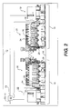
- Fig. 2 is a cutaway view of an exemplary disclosed power system that may be used with the power facility of Fig. 1 ;
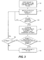
- Fig. 3 is a flow chart depicting an exemplary disclosed operation associated with the power system of Fig. 2 .
- Fig. 1 illustrates a power facility 10 having a power system 12 configured to supply electricity to a power load 14.
- power facility 10 may alternatively embody, for example, a stationary land-based power plant.
- Power facility 10 may include an anchor platform 16 such as a support frame connected to a hull of power facility 10, and to which power system 12 may be mounted. It is contemplated that power system 12 may be rigidly or flexibly mounted to anchor platform 16.
- power load 14 may include any device or devices that require uninterrupted electricity to perform one or more tasks, including, but not limited, electric lights and electric drive motors associated with the depicted marine vessel.
- power load 14 may require electric power in a particular form, such as three-phase alternating current.
- power system 12 may include at least two closely-located power sources 18 operable to generate electricity, and a power-transmission network such as a common bus 19 for transferring electricity from power sources 18 to power load 14 (referring to Fig. 1 ).
- each power source 18 may include an engine 20 drivingly coupled to a generator 22 to form a generator set.
- the generator sets may alternatively be located side-by-side or in a random arrangement within a common power room.
- Each engine 20 may be any type of heat engine operable to produce mechanical power by combusting fuel, including, but not limited to, a diesel engine, a heavy fuel engine, a gasoline engine, and a gaseous-fuel-powered engine.
- each engine 20 may be imbalanced. That is, each engine 20 may have an odd number of cylinders 24 resulting in a free mass or free mass moment.
- engine 20 may include nine cylinders 24. With respect to the nine-cylinder example, four pistons 26 may connected to a common crankshaft 28 and be moving upward, while five piston 26 also connected to crankshaft 28 are moving downward. As a result of the unbalanced masses and their movements, there will be a greater resultant force in the downward direction of this example.
- This greater force is known as a free mass. If unaccounted for, the free mass can induce significant vibrations into anchor platform 16. And, when multiple engines 20 are proximally located and operating in phase with each other (i.e., crankshafts 28 of each engine 20 are oriented at about the same angle and rotating at about the same speed), the magnitude of the amplified vibrations may be excessive.
- a sensor 30 may be associated with each engine 20 to detect an instantaneous position of each crankshaft 28.
- sensor 30 may embody, for example, an impulse transmitter configured to generate a pulse signal each time crankshaft 28 passes through a particular angle. For example, when crankshaft 28 of one engine 20 rotates the majority of pistons 26 to pass through a top dead center (TDC) position, the associated impulse transmitter may generate a first electronic pulse. Similarly, when crankshaft 28 of a second engine 20 rotates the majority of pistons 26 to pass through a bottom dead center (BDC) position, the associated impulse transmitter may generate a second electronic pulse.
- TDC top dead center
- BDC bottom dead center
- the engines when the first and second electronic pulses are generated at about the same time, the engines may be about 180° out of phase and the resulting vibrations may substantially dampen or even cancel each other completely.
- a greater time between the first and second pulses may correspond with engines 20 that are substantially in phase with each other and the resulting vibrations may be additive.
- sensor 30 may alternatively be associated with generators 22, for example with rotors that are directly driven by engine 20, and/or with windings of generators 22.
- Each generator 22 may be any type of power producing device mechanically coupled to receive power from engine 20 and convert at least a portion of that mechanical power into electricity.
- each generator 22 may embody an AC induction generator, a permanent-magnet generator, an AC synchronous generator, or a switched-reluctance generator.
- each generator 22 may include seven pairings of poles (not shown), each pairing having three phases arranged on a circumference of a stator (not shown) to produce an alternating current with a frequency of 60 Hz.
- Power system 12 may also include a synchronizing and load sharing controller 32 to regulate operation of power system 12.
- Controller 32 may include commonly known components that cooperate to synchronize the electrical output of multiple power sources 18 and combine the output into a common supply of power directed to load 14 (referring to Fig 1 ).
- controller 32 may include, among other things, one or more breakers (not shown) connected between each generator 22 and common bus 19 and/or between common bus 19 and power load 14 to selective connect the electrical output from one or both generators 22 to common bus 19 and/or to selectively connect common bus 19 to power load 14.
- controller 32 may be in communication with each engine 20, each generator 22, and sensors 30 to monitor and/or control one or more aspects of generator set operation.
- Controller 32 may further include one or more sensing devices (not shown) to receive input regarding characteristics of electricity generated by each power source 18 such as the current, frequency, phase, and/or voltage. Additionally, controller 32 may receive information relating to the amount of power required by power load 14. For example, controller 32 may receive information such as the voltage and/or current along one or more portions of common bus 19, and the voltage and/or current in one or more components of power load 14.
- Closing a first breaker associated with a first one of generators 22 may electrically connect the output of that generator 22 to common bus 19.
- Controller 32 may regulate operation of the additional power source 18 (i.e., engine 20 and/or generator 22) to vary the electrical output characteristics of the produced power and match the electrical output characteristics of the first generator 22.
- a breaker close command may be issued by controller 32 to the breaker associated with the second generator 22 and, after a brief actuation delay, the breaker may close.
- Controller 32 in addition to synchronizing the power outputs of multiple generators 22, may also control mechanical synchronization of the engines 20 driving those generators 22. Specifically, after electrical synchronization and before controller 32 issues the breaker close command in an attempt to bring additional generators 22 online, controller 32 may first check via sensors 30 to see if the associated first and additional engines 20 are operating in phase with each other (i.e., if the majority of pistons 26 from one engine 20 are moving to TDC at about the same time as the majority of pistons 26 from the second engine 20). If the associated engines 20 are operating sufficiently out of phase with each, controller 32 may go ahead and issue the breaker close command.
- controller 32 may postpone bringing the additional generators 22 online and abort the current synchronization attempt. Controller 32 may initiate another synchronization attempt and repeat the same synchronization cycle a number of times. In one embodiment, controller 32 may attempt dual synchronization (electrical and mechanical) up to ten times before initiating a backup strategy. During the backup strategy, controller 32 may issue the breaker close command regardless of mechanical synchronization. In this manner, load 14 may experience only a minor delay in power supply when mechanical synchronization is unsuccessful.
- Fig. 3 is a flow chart depicting an exemplary operation of power system 12. Fig. 3 will be discussed in the following section to further illustrate the disclosed system and its operation.
- the disclosed power system may have application wherever electrical and mechanical balancing is desired, for example, when multiple power sources having imbalanced moving masses are proximally located.
- electrical and mechanical synchronizing i.e., dual synchronizing
- each power source 18 may be started, and power from one source 18 may be directed to common bus 19 (Step 100).
- the associated engine 20 may be brought up to speed to drive the connected generators 22. In some situations, bringing engine 20 up to speed may include cranking to initiate combustion. In other situations, engine 20 may already be operating, but at only a standby level.
- controller 32 may issue a breaker close command to electrically connect the output of that generator 22 to common bus 19.
- additional generators 22 may also be producing power at the level demanded by load 14, they may remain isolated from common bus 19 until the power output from the additional generators 22 substantially match the power output of the first connected generator 22.
- Controller 32 may match the power output from additional generators 22 to that of the first connected generator 22 before additional connections to common bus 19 may be made (Step 110). Controller 32 may regulate operational characteristics of the additional engines 20 and/or generators 22 to vary and substantially match frequencies, phase angles, and voltages. Once controller 32 determines that the power output of any additional generators 22 substantially match the power output of the first connected generator 22 (Step 120), controller 32 may check the mechanical synchronization between engines 20. That is, controller 32 may compare the mechanical phase angle of the engine 20 associated with the first connected generator 22 with the mechanical phase angle of the remaining engines 20 via sensors 30 (Step 130).
- controller 32 may issue additional breaker close commands to connect the remaining generators 22 to common bus 19 (Step 150).
- the acceptable range is 170-190°.
- controller 32 may abort the current synchronizing attempt and determine the number of attempts made thus far in the process (Step 160). If the number of attempts is less than an acceptable number, for example ten attempts, the process may be restarted by returning control to step 110. However, if the acceptable number of attempts has been made, controller 32 may, instead, connect the electrical output from the additional generators 22 to common bus 19 regardless of mechanical synchronization (Step 150). In this manner, when mechanical synchronization is not possible or has been unsuccessful, power supply delays associated with an excessive number of attempts may be minimized.
- controller 32 may also control both electrical and mechanical synchronization of more than two generator sets. It should be noted, however, that if more that two generator sets are to mechanically synchronized, the out-of-phase angle would be different than disclosed above (i.e., different than 180°) and a function of the number of engines requiring mechanical synchronization.
- engine 20 may include nine cylinders 24.
- a power system for use in a power facility may has a first generator set with a first engine drivingly coupled to a first generator, and a second generator set with a second engine drivingly coupled to a second generator.
- the power system may also have a common bus, and a controller in communication with the first and second generator sets.
- the controller may be configured to direct power from the first generator to the common bus, and synchronize a power output from the second generator with a power output from the first generator.
- the controller may be further configured to postpone power from the second generator being directed to the common bus until the first and second engines are substantially mechanically synchronized.
Landscapes
- Engineering & Computer Science (AREA)
- Power Engineering (AREA)
- Chemical & Material Sciences (AREA)
- Combustion & Propulsion (AREA)
- Mechanical Engineering (AREA)
- Ocean & Marine Engineering (AREA)
- Supply And Distribution Of Alternating Current (AREA)
- Control Of Eletrric Generators (AREA)
Abstract
Description
- The present disclosure relates generally to a power system and, more particularly, to a power system having dual synchronization.
- Many power systems have multiple generator sets for supplying electricity to power loads. Often, these generator sets are connected to supply the power in parallel via a common bus. After one generator set is connected to the common bus, any additional generator sets connected to the bus should produce power matching the voltage, frequency, and phase angle of the power produced by the first generator set. This matching is also known as electrically synchronizing the generator sets. A better sync, results in a smoother transition and a lower shock on the generator and load.
- When multiple generators are located near each other, as is the case in a common power plant or onboard a large marine vessel, vibrations from the various generator sets can travel through the mountings thereof and either dampen or amplify. Vibrations within the power plant or onboard the marine vessel can be excessive when the engines of the generator sets have odd numbers of cylinders. That is, an engine having an odd number of cylinders is mechanically unbalanced. For example, in a nine-cylinder engine, four pistons may be moving upward, while five pistons are moving downward. As a result of the unbalanced masses and their movements, there will be a greater resultant force in the downward direction of this example. Dependent on the weight and speed of such an engine, the size of the pistons, and the type of mounting (rigid or flexible), this force could be significant enough to transmit vibrations into the engine mounts and surrounding supports with enough amplitude that structural damage could occur and/or that the vibrations become a nuisance for the engine owner/operator. This is also a problem when multiple engines located near each other are operated in sync with each other (i.e., when eight pistons are moving upward and ten are moving downward, as would be the case with two closely operating nine-cylinder engines).
- One system addressing the issue of synchronizing multiple generator sets is described in
U.S. Patent No. 6,552,454 (the '454 patent) issued to Kern et al. on April 22, 2003. The '454 patent discloses a generator structure having first and second generator sets positioned within a common enclosure. Each generator set includes an engine and an alternator driven by the engine for generating electrical power. The first generator set produces electrical power of a first magnitude and frequency, and the second generator set produces electrical power of a second magnitude and frequency. The generator structure also includes a controller that monitors the magnitude and phase of the electrical power produced by the first and second generator sets, and adjusts the speed of the engines via an electronic governor such the power produced by the first and second generators is brought into alignment with each other, no phase difference between the associated sine waves exist, and so that the sine waves are at the same frequency. In addition, the system controller regulates the output voltages of the generator sets such that the output voltages are generally equal. Once the frequency and output voltages are synchronized, the system controller closes switches to connect the power from the first and second generator sets to a load. - A very similar generator structure as the one of '454 patent is described in
DE196 20 586 A1 (the '586 patent). - Although the generator structures of the '454 patent or the '586 patent may allow phase, frequency, and voltage matching, it does little to account for vibrations caused by imbalanced engines. And, because the generator sets are close-coupled in a common enclosure, depending on when the engines are electrically synchronized, it may be possible for the two generators to be electrically synchronized when the two associated engines are in phase with each other. And, if the engines are in phase enough and imbalanced, the vibrations could be severe enough to damage the common enclosure.
- In
JP 06-245390 - Another power system as disclosed in
JP 03-134897 - In
US 6,552,454 B2 a generator structure is provided for generating electrical power. The generator structure includes an enclosure having first and second spaced sidewalls interconnected by first and second end walls so as to define an interior. First and second generator sets are positioned within the interior of the enclosure. Each generator set includes an engine, an alternator driven by the engine for generating the electrical power and a radiator operatively connected to the engine. Means are provided for synchronizing the electrical power generated by each alternator. -
WO 2009/013155 A2 published later than the filing date of the present document shows a first generator, which is driven by a first diesel engine. This first generator is connected to an electrical power supply system, in particular an on-board power supply system in a marine vessel. The electrical power supply system is also fed by a second generator which is driven by a second diesel engine. The time of connection of the first generator is chosen as a function of the frequency and phase angle of the output voltage of the first generator with respect to the frequency and phase angle of the power supply system. Undesirably high levels of vibration produced by the diesel engines can be avoided by choosing the time of connection additionally as a function of the position and movement direction of a piston of the first diesel engine with respect to the piston and movement direction of a piston of the second diesel engine. - The power system of the present disclosure addresses one or more of the problems set forth above.
- In one aspect, the present disclosure is directed toward a power system. The power system comprises a first generator set having a first engine drivingly coupled to a first generator, a second generator set having a second engine drivingly coupled to a second generator, a common bus, and a controller in communication with the first and second generator sets. The controller may be configured to direct power from the first generator to the common bus, synchronize a power output from the second generator with a power output from the first generator, and postpone power from the second generator being directed to the common bus until the rotational angles of the first and second engines are within 170-190° out of phase with each other.
- In another aspect, the present disclosure is directed toward a method of providing power. The method includes operating a first power source to produce electrical power, and directing power from the first power source to a common bus. The method further includes operating a second power source to produce electrical power, and synchronizing a power output from the second power source with a power output from the first power source. The method additionally includes postponing directing power from the second power source to the common bus until the first and second engines of the two power sources are substantially mechanically synchronized, i.e. the rotational angles of the first and second engines are within 170-190° out of phase with each other.
- In yet another aspect, the present disclosure is directed toward a power facility. The power facility comprises a common anchor platform and a power system of the type mentioned above. The first generator set is mounted to the common anchor platform and has a first mass-imbalanced engine drivingly coupled to a first generator. The second generator set is mounted to the common anchor platform in proximity to the first generator set and has a second mass-imbalanced engine drivingly coupled to a second generator. The common bus is configured to transmit electrical power from the first and second generator sets to a power load. In addition, the controller is configured to postpone power from the second generator being directed to the common bus until the first and second mass-imbalanced engines are substantially mechanically synchronized, i.e. the rotational angles of the first and second engines are within 170-190° out of phase with each other, and a vibrational input directed from the first generator set into the common anchor platform is at least partially dampened by a vibrational input from the second generator set.
-
Fig. 1 is a pictorial illustration of one exemplary disclosed power facility -
Fig. 2 is a cutaway view of an exemplary disclosed power system that may be used with the power facility ofFig. 1 ; and -
Fig. 3 is a flow chart depicting an exemplary disclosed operation associated with the power system ofFig. 2 . -
Fig. 1 illustrates apower facility 10 having apower system 12 configured to supply electricity to apower load 14. Although illustrated as a marine vessel inFig. 1 ,power facility 10 may alternatively embody, for example, a stationary land-based power plant.Power facility 10 may include ananchor platform 16 such as a support frame connected to a hull ofpower facility 10, and to whichpower system 12 may be mounted. It is contemplated thatpower system 12 may be rigidly or flexibly mounted to anchorplatform 16. - In the embodiment of
Fig. 1 ,power load 14 may include any device or devices that require uninterrupted electricity to perform one or more tasks, including, but not limited, electric lights and electric drive motors associated with the depicted marine vessel. - In some embodiments,
power load 14 may require electric power in a particular form, such as three-phase alternating current. - As illustrated in
Fig. 2 ,power system 12 may include at least two closely-locatedpower sources 18 operable to generate electricity, and a power-transmission network such as acommon bus 19 for transferring electricity frompower sources 18 to power load 14 (referring toFig. 1 ). In one embodiment, eachpower source 18 may include anengine 20 drivingly coupled to agenerator 22 to form a generator set. Although shown end-to-end, the generator sets may alternatively be located side-by-side or in a random arrangement within a common power room. - Each
engine 20 may be any type of heat engine operable to produce mechanical power by combusting fuel, including, but not limited to, a diesel engine, a heavy fuel engine, a gasoline engine, and a gaseous-fuel-powered engine. In the illustrated embodiment, eachengine 20 may be imbalanced. That is, eachengine 20 may have an odd number ofcylinders 24 resulting in a free mass or free mass moment. In one specific embodiment,engine 20 may include ninecylinders 24. With respect to the nine-cylinder example, fourpistons 26 may connected to acommon crankshaft 28 and be moving upward, while fivepiston 26 also connected to crankshaft 28 are moving downward. As a result of the unbalanced masses and their movements, there will be a greater resultant force in the downward direction of this example. This greater force is known as a free mass. If unaccounted for, the free mass can induce significant vibrations intoanchor platform 16. And, whenmultiple engines 20 are proximally located and operating in phase with each other (i.e.,crankshafts 28 of eachengine 20 are oriented at about the same angle and rotating at about the same speed), the magnitude of the amplified vibrations may be excessive. - A
sensor 30 may be associated with eachengine 20 to detect an instantaneous position of eachcrankshaft 28. In one embodiment,sensor 30 may embody, for example, an impulse transmitter configured to generate a pulse signal each time crankshaft 28 passes through a particular angle. For example, when crankshaft 28 of oneengine 20 rotates the majority ofpistons 26 to pass through a top dead center (TDC) position, the associated impulse transmitter may generate a first electronic pulse. Similarly, when crankshaft 28 of asecond engine 20 rotates the majority ofpistons 26 to pass through a bottom dead center (BDC) position, the associated impulse transmitter may generate a second electronic pulse. In this example, when the first and second electronic pulses are generated at about the same time, the engines may be about 180° out of phase and the resulting vibrations may substantially dampen or even cancel each other completely. In contrast, a greater time between the first and second pulses may correspond withengines 20 that are substantially in phase with each other and the resulting vibrations may be additive. It is contemplated thatsensor 30 may alternatively be associated withgenerators 22, for example with rotors that are directly driven byengine 20, and/or with windings ofgenerators 22. - Each
generator 22 may be any type of power producing device mechanically coupled to receive power fromengine 20 and convert at least a portion of that mechanical power into electricity. For example, eachgenerator 22 may embody an AC induction generator, a permanent-magnet generator, an AC synchronous generator, or a switched-reluctance generator. In one embodiment, eachgenerator 22 may include seven pairings of poles (not shown), each pairing having three phases arranged on a circumference of a stator (not shown) to produce an alternating current with a frequency of 60 Hz. -
Power system 12 may also include a synchronizing and load sharing controller 32 to regulate operation ofpower system 12. Controller 32 may include commonly known components that cooperate to synchronize the electrical output ofmultiple power sources 18 and combine the output into a common supply of power directed to load 14 (referring toFig 1 ). For example, controller 32 may include, among other things, one or more breakers (not shown) connected between eachgenerator 22 andcommon bus 19 and/or betweencommon bus 19 andpower load 14 to selective connect the electrical output from one or bothgenerators 22 tocommon bus 19 and/or to selectively connectcommon bus 19 topower load 14. In addition, controller 32 may be in communication with eachengine 20, eachgenerator 22, andsensors 30 to monitor and/or control one or more aspects of generator set operation. Controller 32 may further include one or more sensing devices (not shown) to receive input regarding characteristics of electricity generated by eachpower source 18 such as the current, frequency, phase, and/or voltage. Additionally, controller 32 may receive information relating to the amount of power required bypower load 14. For example, controller 32 may receive information such as the voltage and/or current along one or more portions ofcommon bus 19, and the voltage and/or current in one or more components ofpower load 14. - Closing a first breaker associated with a first one of
generators 22 may electrically connect the output of thatgenerator 22 tocommon bus 19. To electrically connect anadditional generator 22 tocommon bus 19, it may be required that the output of theadditional generator 22 have a voltage, frequency, and phase angle that substantially matches the voltage, frequency, and phase angle of the first connectedgenerator 22. A better match may result in a smoother transition and a lower shock onpower load 14. Controller 32 may regulate operation of the additional power source 18 (i.e.,engine 20 and/or generator 22) to vary the electrical output characteristics of the produced power and match the electrical output characteristics of thefirst generator 22. Once all synchronization conditions (i.e., frequency, phase angle, and voltage) have been met, a breaker close command may be issued by controller 32 to the breaker associated with thesecond generator 22 and, after a brief actuation delay, the breaker may close. - Controller 32, in addition to synchronizing the power outputs of
multiple generators 22, may also control mechanical synchronization of theengines 20 driving thosegenerators 22. Specifically, after electrical synchronization and before controller 32 issues the breaker close command in an attempt to bringadditional generators 22 online, controller 32 may first check viasensors 30 to see if the associated first andadditional engines 20 are operating in phase with each other (i.e., if the majority ofpistons 26 from oneengine 20 are moving to TDC at about the same time as the majority ofpistons 26 from the second engine 20). If the associatedengines 20 are operating sufficiently out of phase with each, controller 32 may go ahead and issue the breaker close command. However, if the associatedengines 20 are operating insufficiently out of phase, controller 32 may postpone bringing theadditional generators 22 online and abort the current synchronization attempt. Controller 32 may initiate another synchronization attempt and repeat the same synchronization cycle a number of times. In one embodiment, controller 32 may attempt dual synchronization (electrical and mechanical) up to ten times before initiating a backup strategy. During the backup strategy, controller 32 may issue the breaker close command regardless of mechanical synchronization. In this manner, load 14 may experience only a minor delay in power supply when mechanical synchronization is unsuccessful. -
Fig. 3 is a flow chart depicting an exemplary operation ofpower system 12.Fig. 3 will be discussed in the following section to further illustrate the disclosed system and its operation. - The disclosed power system may have application wherever electrical and mechanical balancing is desired, for example, when multiple power sources having imbalanced moving masses are proximally located. During operation of the disclosed power system, electrical and mechanical synchronizing (i.e., dual synchronizing) may be performed to produce a common electrical power supply and to simultaneously dampen vibrations associated with the power sources. Operation of
power system 12 will now be described. - To initiate operation of
power system 12, eachpower source 18 may be started, and power from onesource 18 may be directed to common bus 19 (Step 100). To start eachpower source 18, the associatedengine 20 may be brought up to speed to drive theconnected generators 22. In some situations, bringingengine 20 up to speed may include cranking to initiate combustion. In other situations,engine 20 may already be operating, but at only a standby level. Once the output a first ofengines 20 is brought up to speed and theconnected generator 22 is producing power at a level demanded byload 14, controller 32 may issue a breaker close command to electrically connect the output of thatgenerator 22 tocommon bus 19. Althoughadditional generators 22 may also be producing power at the level demanded byload 14, they may remain isolated fromcommon bus 19 until the power output from theadditional generators 22 substantially match the power output of the first connectedgenerator 22. - Controller 32 may match the power output from
additional generators 22 to that of the first connectedgenerator 22 before additional connections tocommon bus 19 may be made (Step 110). Controller 32 may regulate operational characteristics of theadditional engines 20 and/orgenerators 22 to vary and substantially match frequencies, phase angles, and voltages. Once controller 32 determines that the power output of anyadditional generators 22 substantially match the power output of the first connected generator 22 (Step 120), controller 32 may check the mechanical synchronization betweenengines 20. That is, controller 32 may compare the mechanical phase angle of theengine 20 associated with the first connectedgenerator 22 with the mechanical phase angle of the remainingengines 20 via sensors 30 (Step 130). If controller 32 determines that the mechanical phase angle of the remainingengines 20 are synchronized within an acceptable range of theengine 20 driving the first connected generator (Step 140), controller 32 may issue additional breaker close commands to connect the remaininggenerators 22 to common bus 19 (Step 150). In one embodiment, the acceptable range is 170-190°. - If controller 32 determines that the mechanical phase angle of the remaining engines are not synchronized within the acceptable range, controller 32 may abort the current synchronizing attempt and determine the number of attempts made thus far in the process (Step 160). If the number of attempts is less than an acceptable number, for example ten attempts, the process may be restarted by returning control to step 110. However, if the acceptable number of attempts has been made, controller 32 may, instead, connect the electrical output from the
additional generators 22 tocommon bus 19 regardless of mechanical synchronization (Step 150). In this manner, when mechanical synchronization is not possible or has been unsuccessful, power supply delays associated with an excessive number of attempts may be minimized. - It will be apparent to those skilled in the art that various modifications and variations can be made in the disclosed power system and method without departing from the scope of the disclosure. Other embodiments of the disclosed power system will be apparent to those skilled in the art from consideration of the specification and practice of the power system and methods disclosed herein. For example, although
power system 12 has been described primarily with respect to only two generator sets, it is contemplated that controller 32 may also control both electrical and mechanical synchronization of more than two generator sets. It should be noted, however, that if more that two generator sets are to mechanically synchronized, the out-of-phase angle would be different than disclosed above (i.e., different than 180°) and a function of the number of engines requiring mechanical synchronization. Further, although intended primarily for imbalanced engines (i.e., engines having an odd number of cylinders resulting in a free mass), the dual synchronization of the current disclosure may be applied just as easily to an engine having an even number of cylinders but still experiencing excessive vibrations. In one specific embodiment,engine 20 may include ninecylinders 24. - Generally, a power system for use in a power facility is disclosed. The power system may has a first generator set with a first engine drivingly coupled to a first generator, and a second generator set with a second engine drivingly coupled to a second generator. The power system may also have a common bus, and a controller in communication with the first and second generator sets. The controller may be configured to direct power from the first generator to the common bus, and synchronize a power output from the second generator with a power output from the first generator. The controller may be further configured to postpone power from the second generator being directed to the common bus until the first and second engines are substantially mechanically synchronized.
- It is intended that the specification and examples be considered as exemplary only, with a true scope of the disclosure being indicated by the following claims and their equivalents.
Claims (15)
- A power system (12), comprising:- a first generator set having a first engine (20) drivingly coupled to a first generator (22);- a second generator set having a second engine (20) drivingly coupled to a second generator (22);- a common bus (19); and- a controller (32) in communication with the first and second generator sets, the controller (32) being configured to:direct power from the first generator (22) to the common bus (19);synchronize a power output from the second generator (22) with a power output from the first generator (22); andpostpone power from the second generator (22) being directed to the common bus (19) until the rotational angles of the first and second engines (20, 20) are within 170-190° out of phase with each other.
- The power system (12) of claim 1, wherein the power output from the second generator (22) is synchronized with the power output from the first generator (22) when at least one of a phase angle, a frequency, and a voltage of the power outputs from the first and second generators (22, 22) are substantially matched.
- The power system (12) of claim 1, further including:- a first sensor (30) situated to generate a first signal indicative of a rotational angle of the first engine (20); and- a second sensor (30) situated to generate a second signal indicative of a rotational angle of the second engine (20),
wherein the controller (32) is configured to compare the first and second signals after synchronizing the power output of the second generator (22) with the power output of the first generator (22). - The power system (12) of claim 1, wherein the controller (32) is configured to direct power from the second generator (22) to the common bus (19) only when the rotational angles of the first and second engines (20, 20) are about 180° out of phase with each other.
- The power system of claim 1, wherein the controller is further configured to:attempt mechanical synchronization a number of times; anddirect power from the second generator (22) to the common bus (19) after power output synchronization regardless of mechanical synchronization when the number of attempts has been made.
- The power system (12) of claim 5, wherein the number of attempts is ten.
- The power system (12) of claim 1, wherein at least one of the first and second engines (20, 20) has an imbalanced rotational mass.
- The power system (12) of claim 7, wherein the imbalanced rotational mass is caused by the at least one of the first and second engines (20, 20) having an odd number of cylinders (24).
- The power system (12) of claim 8, wherein the first and second engines (20, 20) are substantially identical and include nine cylinders (24) each.
- The power system (12) of claim 1, wherein the first and second engines (20, 20) are mounted to a common anchor platform (16).
- A method of providing power, comprising:- operating a first power source (18) to produce electrical power by means of a first engine (20);- operating a second power source (18) to produce electrical power by means of a second engine (20);- directing power from the first power source (18) to a common bus (19);- synchronizing a power output from the second power source (18) with a power output from the first power source (18);
and- postponing directing power from the second power source (18) to the common bus (19) until the rotational angles of the first and second engines (20, 20) are within 170-190° out of phase with each other. - The method of claim 11, wherein the power output from the second power source (18) is synchronized with the power output from the first power source (18) when a phase angle, a frequency, and a voltage of the power outputs from the first and second power sources (18, 18) are substantially matched.
- The method of claim 11, further including:- sensing a first rotational angle of the first power source (18);- sensing a second rotational angle of the second power source (18);
and- comparing the first and second rotational angles after synchronizing the power output of the second power source (18) with the power output of the first power source (18). - The method of claim 13, further including:- attempting mechanical synchronization a number of times; and- directing power from the second power source (18) to the common bus (19) after power output synchronization regardless of mechanical synchronization when the number of attempts has been made.
- A power facility, comprising:- a common anchor platform (16); and- a power system of any one of claims 1 to 9;
the first generator set being mounted to the common anchor platform (16) and having a first mass-imbalanced engine (20) drivingly coupled to a first generator (22);
the second generator set being mounted to the common anchor platform (16) in proximity to the first generator set and having a second mass-imbalanced engine (20) drivingly coupled to a second generator (22);- the common bus (19) being configured to transmit electrical power from the first and second generator sets to a power load; and- the controller (32) being configured to postpone power from the second generator (22) being directed to the common bus (19) the rotational angles of the first and second engines (20, 20) are within 170-190° out of phase with each other, and a vibrational input directed from the first generator set into the common anchor platform (16) is at least partially dampened by a vibrational input from the second generator set.
Applications Claiming Priority (2)
| Application Number | Priority Date | Filing Date | Title |
|---|---|---|---|
| EP20070839713 EP2201673B1 (en) | 2007-10-19 | 2007-10-19 | Power system having dual synchronization |
| PCT/US2007/022352 WO2009051585A1 (en) | 2007-10-19 | 2007-10-19 | Power system having dual synchronization |
Related Parent Applications (1)
| Application Number | Title | Priority Date | Filing Date |
|---|---|---|---|
| EP20070839713 Division EP2201673B1 (en) | 2007-10-19 | 2007-10-19 | Power system having dual synchronization |
Publications (1)
| Publication Number | Publication Date |
|---|---|
| EP2346159A1 true EP2346159A1 (en) | 2011-07-20 |
Family
ID=39595772
Family Applications (2)
| Application Number | Title | Priority Date | Filing Date |
|---|---|---|---|
| EP11162071A Withdrawn EP2346159A1 (en) | 2007-10-19 | 2007-10-19 | Power system having a dual synchronization |
| EP20070839713 Not-in-force EP2201673B1 (en) | 2007-10-19 | 2007-10-19 | Power system having dual synchronization |
Family Applications After (1)
| Application Number | Title | Priority Date | Filing Date |
|---|---|---|---|
| EP20070839713 Not-in-force EP2201673B1 (en) | 2007-10-19 | 2007-10-19 | Power system having dual synchronization |
Country Status (7)
| Country | Link |
|---|---|
| US (1) | US8432065B2 (en) |
| EP (2) | EP2346159A1 (en) |
| KR (1) | KR101409513B1 (en) |
| CN (1) | CN101828331B (en) |
| AT (1) | ATE513357T1 (en) |
| DE (1) | DE202008013891U1 (en) |
| WO (1) | WO2009051585A1 (en) |
Cited By (2)
| Publication number | Priority date | Publication date | Assignee | Title |
|---|---|---|---|---|
| US8716896B2 (en) | 2008-12-12 | 2014-05-06 | Caterpillar Inc. | Genset control system implementing engine synchronization |
| CN105715363A (en) * | 2016-03-21 | 2016-06-29 | 江苏鲲鹏电力设备有限公司 | Fuel-saved and energy-saved diesel generator |
Families Citing this family (7)
| Publication number | Priority date | Publication date | Assignee | Title |
|---|---|---|---|---|
| DE102007019202B4 (en) * | 2007-04-20 | 2015-05-21 | Wirtgen Gmbh | Self-propelled construction machine, in particular road milling machine, recycler or stabilizer |
| DE102009043530A1 (en) * | 2009-09-30 | 2011-04-07 | Siemens Aktiengesellschaft | Electric drive shaft and vehicle with such an electric drive shaft |
| US8746382B2 (en) * | 2010-12-23 | 2014-06-10 | Caterpillar Inc. | Switched reluctance generator priming strategy |
| CN102307036B (en) * | 2011-03-15 | 2013-06-19 | 隆鑫通用动力股份有限公司 | Control method and device for parallel running of internal combustion engine-driven generating sets |
| CN108475924B (en) * | 2015-12-18 | 2021-04-23 | 瓦锡兰芬兰有限公司 | Power plant and method for controlling power plant |
| US9964984B2 (en) | 2016-03-31 | 2018-05-08 | Caterpillar Inc. | System for controlling load sharing |
| US9988135B2 (en) | 2016-03-31 | 2018-06-05 | Caterpillar Inc. | System for controlling an electrical power system |
Citations (8)
| Publication number | Priority date | Publication date | Assignee | Title |
|---|---|---|---|---|
| GB326857A (en) * | 1928-10-19 | 1930-03-19 | British Thomson Houston Co Ltd | Improvements in and relating to means for reducing vibration due to reciprocating machinery and apparatus therefor |
| JPH01194900A (en) * | 1988-01-29 | 1989-08-04 | Meidensha Corp | Controller for engine generator |
| JPH03134897A (en) | 1989-10-20 | 1991-06-07 | Toshiba Corp | Non-volatile memory |
| JPH06245390A (en) | 1993-02-16 | 1994-09-02 | Mitsubishi Heavy Ind Ltd | Phase controller for generating engine |
| DE19620586A1 (en) | 1996-05-22 | 1997-11-27 | Blohm & Voss Int | Uninterrupted current supply (UCS) system on board ship with two electrical plants |
| US20030011258A1 (en) * | 2001-07-12 | 2003-01-16 | Kern Robert D. | Generator structure incorporating multiple electrical generator sets |
| JP2003134897A (en) * | 2001-10-22 | 2003-05-09 | Nishishiba Electric Co Ltd | Power generator parallel operation device and its parallel operation method |
| WO2009013155A2 (en) | 2007-07-20 | 2009-01-29 | Siemens Aktiengesellschaft | Method and apparatus for connection of a generator, which is driven by a diesel engine, to an electrical power supply system |
Family Cites Families (7)
| Publication number | Priority date | Publication date | Assignee | Title |
|---|---|---|---|---|
| SU437173A1 (en) | 1973-01-02 | 1974-07-25 | Предприятие П/Я В-2156 | The method of switching on the parallel operation of diesel-generator sets |
| US4121423A (en) * | 1977-05-31 | 1978-10-24 | Automotive Propulsion Laboratories, Ltd. | Compound internal-combustion hot-gas engines |
| SU1539893A1 (en) | 1987-01-12 | 1990-01-30 | Организация П/Я А-3500 | Device for connection of synchronous generators for parallel operation |
| TW586262B (en) * | 1999-02-16 | 2004-05-01 | Exxonmobil Upstream Res Co | Systems and methods for utilizing excess electric power from a marine transportation vessel |
| US6245390B1 (en) * | 1999-09-10 | 2001-06-12 | Viatcheslav Baranovski | High-velocity thermal spray apparatus and method of forming materials |
| RU2212356C1 (en) | 2002-03-22 | 2003-09-20 | Калининградский военный институт ФПС РФ | Device for parallel operation of shaft-diesel- generator set |
| JP4270445B2 (en) * | 2003-10-17 | 2009-06-03 | 本田技研工業株式会社 | Output generator for synchronous generator |
-
2007
- 2007-10-19 EP EP11162071A patent/EP2346159A1/en not_active Withdrawn
- 2007-10-19 WO PCT/US2007/022352 patent/WO2009051585A1/en not_active Ceased
- 2007-10-19 EP EP20070839713 patent/EP2201673B1/en not_active Not-in-force
- 2007-10-19 US US12/738,589 patent/US8432065B2/en not_active Expired - Fee Related
- 2007-10-19 KR KR1020107008275A patent/KR101409513B1/en not_active Expired - Fee Related
- 2007-10-19 AT AT07839713T patent/ATE513357T1/en not_active IP Right Cessation
- 2007-10-19 CN CN2007801011340A patent/CN101828331B/en not_active Expired - Fee Related
-
2008
- 2008-10-17 DE DE202008013891U patent/DE202008013891U1/en not_active Expired - Lifetime
Patent Citations (9)
| Publication number | Priority date | Publication date | Assignee | Title |
|---|---|---|---|---|
| GB326857A (en) * | 1928-10-19 | 1930-03-19 | British Thomson Houston Co Ltd | Improvements in and relating to means for reducing vibration due to reciprocating machinery and apparatus therefor |
| JPH01194900A (en) * | 1988-01-29 | 1989-08-04 | Meidensha Corp | Controller for engine generator |
| JPH03134897A (en) | 1989-10-20 | 1991-06-07 | Toshiba Corp | Non-volatile memory |
| JPH06245390A (en) | 1993-02-16 | 1994-09-02 | Mitsubishi Heavy Ind Ltd | Phase controller for generating engine |
| DE19620586A1 (en) | 1996-05-22 | 1997-11-27 | Blohm & Voss Int | Uninterrupted current supply (UCS) system on board ship with two electrical plants |
| US20030011258A1 (en) * | 2001-07-12 | 2003-01-16 | Kern Robert D. | Generator structure incorporating multiple electrical generator sets |
| US6552454B2 (en) | 2001-07-12 | 2003-04-22 | Generac Power Systems, Inc. | Generator structure incorporating multiple electrical generator sets |
| JP2003134897A (en) * | 2001-10-22 | 2003-05-09 | Nishishiba Electric Co Ltd | Power generator parallel operation device and its parallel operation method |
| WO2009013155A2 (en) | 2007-07-20 | 2009-01-29 | Siemens Aktiengesellschaft | Method and apparatus for connection of a generator, which is driven by a diesel engine, to an electrical power supply system |
Cited By (2)
| Publication number | Priority date | Publication date | Assignee | Title |
|---|---|---|---|---|
| US8716896B2 (en) | 2008-12-12 | 2014-05-06 | Caterpillar Inc. | Genset control system implementing engine synchronization |
| CN105715363A (en) * | 2016-03-21 | 2016-06-29 | 江苏鲲鹏电力设备有限公司 | Fuel-saved and energy-saved diesel generator |
Also Published As
| Publication number | Publication date |
|---|---|
| CN101828331B (en) | 2013-02-13 |
| WO2009051585A1 (en) | 2009-04-23 |
| ATE513357T1 (en) | 2011-07-15 |
| KR20100083791A (en) | 2010-07-22 |
| KR101409513B1 (en) | 2014-06-19 |
| US8432065B2 (en) | 2013-04-30 |
| US20100207457A1 (en) | 2010-08-19 |
| CN101828331A (en) | 2010-09-08 |
| EP2201673A1 (en) | 2010-06-30 |
| EP2201673B1 (en) | 2011-06-15 |
| DE202008013891U1 (en) | 2009-01-08 |
Similar Documents
| Publication | Publication Date | Title |
|---|---|---|
| EP2201673B1 (en) | Power system having dual synchronization | |
| US8716896B2 (en) | Genset control system implementing engine synchronization | |
| US8299638B2 (en) | Propulsion system for ships | |
| US7969044B2 (en) | System having a variable frequency power distribution bus for driving a variable speed motor | |
| JP5839836B2 (en) | Parallel operation controller for inverter generator | |
| US9325271B2 (en) | Parallel running control apparatus for inverter generators | |
| US8097968B2 (en) | Position-controlled start from the AC line using a synchronous machine | |
| JP2012524508A (en) | Method for supplying external energy to an onboard power network in a ship, a ship with such a source of external energy | |
| RU2441306C1 (en) | Power device with double synchronisation | |
| EP4045782B1 (en) | Engine-generator set | |
| JP5839834B2 (en) | Parallel operation controller for inverter generator | |
| EP1595322A1 (en) | Device and method for generating electric current | |
| EP2250719B1 (en) | Vibration dampening arrangement | |
| WO2021086622A1 (en) | Dynamic combustion control of an opposed-piston engine | |
| JP2012244693A (en) | Parallel operation controller of inverter generator | |
| EP3192735A1 (en) | Hybrid engine system | |
| JPH06245390A (en) | Phase controller for generating engine | |
| JP5687559B2 (en) | Parallel operation controller for inverter generator |
Legal Events
| Date | Code | Title | Description |
|---|---|---|---|
| PUAI | Public reference made under article 153(3) epc to a published international application that has entered the european phase |
Free format text: ORIGINAL CODE: 0009012 |
|
| AC | Divisional application: reference to earlier application |
Ref document number: 2201673 Country of ref document: EP Kind code of ref document: P |
|
| AK | Designated contracting states |
Kind code of ref document: A1 Designated state(s): AT BE BG CH CY CZ DE DK EE ES FI FR GB GR HU IE IS IT LI LT LU LV MC MT NL PL PT RO SE SI SK TR |
|
| 17P | Request for examination filed |
Effective date: 20120120 |
|
| 17Q | First examination report despatched |
Effective date: 20141223 |
|
| STAA | Information on the status of an ep patent application or granted ep patent |
Free format text: STATUS: THE APPLICATION IS DEEMED TO BE WITHDRAWN |
|
| 18D | Application deemed to be withdrawn |
Effective date: 20150703 |