EP2346145A2 - Permanent magnet rotor of an electrical machine - Google Patents
Permanent magnet rotor of an electrical machine Download PDFInfo
- Publication number
- EP2346145A2 EP2346145A2 EP11150484A EP11150484A EP2346145A2 EP 2346145 A2 EP2346145 A2 EP 2346145A2 EP 11150484 A EP11150484 A EP 11150484A EP 11150484 A EP11150484 A EP 11150484A EP 2346145 A2 EP2346145 A2 EP 2346145A2
- Authority
- EP
- European Patent Office
- Prior art keywords
- permanent magnets
- letter
- electric machine
- rotating electric
- rotor
- Prior art date
- Legal status (The legal status is an assumption and is not a legal conclusion. Google has not performed a legal analysis and makes no representation as to the accuracy of the status listed.)
- Withdrawn
Links
Images


Classifications
-
- H—ELECTRICITY
- H02—GENERATION; CONVERSION OR DISTRIBUTION OF ELECTRIC POWER
- H02K—DYNAMO-ELECTRIC MACHINES
- H02K1/00—Details of the magnetic circuit
- H02K1/06—Details of the magnetic circuit characterised by the shape, form or construction
- H02K1/22—Rotating parts of the magnetic circuit
- H02K1/27—Rotor cores with permanent magnets
- H02K1/2706—Inner rotors
- H02K1/272—Inner rotors the magnetisation axis of the magnets being perpendicular to the rotor axis
- H02K1/274—Inner rotors the magnetisation axis of the magnets being perpendicular to the rotor axis the rotor consisting of two or more circumferentially positioned magnets
- H02K1/2753—Inner rotors the magnetisation axis of the magnets being perpendicular to the rotor axis the rotor consisting of two or more circumferentially positioned magnets the rotor consisting of magnets or groups of magnets arranged with alternating polarity
- H02K1/276—Magnets embedded in the magnetic core, e.g. interior permanent magnets [IPM]
- H02K1/2766—Magnets embedded in the magnetic core, e.g. interior permanent magnets [IPM] having a flux concentration effect
-
- B—PERFORMING OPERATIONS; TRANSPORTING
- B60—VEHICLES IN GENERAL
- B60K—ARRANGEMENT OR MOUNTING OF PROPULSION UNITS OR OF TRANSMISSIONS IN VEHICLES; ARRANGEMENT OR MOUNTING OF PLURAL DIVERSE PRIME-MOVERS IN VEHICLES; AUXILIARY DRIVES FOR VEHICLES; INSTRUMENTATION OR DASHBOARDS FOR VEHICLES; ARRANGEMENTS IN CONNECTION WITH COOLING, AIR INTAKE, GAS EXHAUST OR FUEL SUPPLY OF PROPULSION UNITS IN VEHICLES
- B60K6/00—Arrangement or mounting of plural diverse prime-movers for mutual or common propulsion, e.g. hybrid propulsion systems comprising electric motors and internal combustion engines
- B60K6/20—Arrangement or mounting of plural diverse prime-movers for mutual or common propulsion, e.g. hybrid propulsion systems comprising electric motors and internal combustion engines the prime-movers consisting of electric motors and internal combustion engines, e.g. HEVs
- B60K6/22—Arrangement or mounting of plural diverse prime-movers for mutual or common propulsion, e.g. hybrid propulsion systems comprising electric motors and internal combustion engines the prime-movers consisting of electric motors and internal combustion engines, e.g. HEVs characterised by apparatus, components or means specially adapted for HEVs
- B60K6/26—Arrangement or mounting of plural diverse prime-movers for mutual or common propulsion, e.g. hybrid propulsion systems comprising electric motors and internal combustion engines the prime-movers consisting of electric motors and internal combustion engines, e.g. HEVs characterised by apparatus, components or means specially adapted for HEVs characterised by the motors or the generators
-
- H—ELECTRICITY
- H02—GENERATION; CONVERSION OR DISTRIBUTION OF ELECTRIC POWER
- H02K—DYNAMO-ELECTRIC MACHINES
- H02K1/00—Details of the magnetic circuit
- H02K1/06—Details of the magnetic circuit characterised by the shape, form or construction
- H02K1/12—Stationary parts of the magnetic circuit
- H02K1/16—Stator cores with slots for windings
-
- H—ELECTRICITY
- H02—GENERATION; CONVERSION OR DISTRIBUTION OF ELECTRIC POWER
- H02K—DYNAMO-ELECTRIC MACHINES
- H02K21/00—Synchronous motors having permanent magnets; Synchronous generators having permanent magnets
- H02K21/12—Synchronous motors having permanent magnets; Synchronous generators having permanent magnets with stationary armatures and rotating magnets
- H02K21/14—Synchronous motors having permanent magnets; Synchronous generators having permanent magnets with stationary armatures and rotating magnets with magnets rotating within the armatures
Definitions
- the present invention relates to a rotor for use in an IPM (interior permanent magnet) rotating electric machine and an IPM rotating electric machine provided with the rotor. Further, the present invention relates to a motor vehicle, a lifting machine, a fluid machine and a processing machine provided with the IPM rotating electric machine.
- IPM internal permanent magnet
- Japanese Patent Application Publication No. 2006-254629 discloses one example of an IPM rotating electric machine in which permanent magnets are embedded in a rotor core and in which electric energy is converted to mechanical energy by use of magnet torque and reluctance torque.
- a plurality of permanent magnets are arranged so that two corresponding permanent magnets define the letter V whose apex points toward the rotation axis of the rotor.
- the two corresponding permanent magnets form a single magnetic pole.
- the two corresponding permanent magnets have a same shape and are arranged symmetrically to each other with respect to a straight line radially extending through the apex of the letter V and the rotation axis.
- the two corresponding permanent magnets are equal to each other in the length (width) parallel to the corresponding side of the letter V, the length (thickness) perpendicular to the corresponding side of the letter V and the angle with respect to the straight line.
- the volume of the rotor core is reduced if one attempts to increase the magnet torque by increasing the input volume of the permanent magnets in an effort to make the output torque greater. This tends to reduce the reluctance torque.
- the volume of the rotor core In order to increase the reluctance torque, there is a need to increase the volume of the rotor core. The increase in the volume of the rotor core, however, would result in a decrease in the input volume of the permanent magnets, eventually reducing the magnet torque.
- the increase of the magnet torque accomplished by increasing the input volume of the permanent magnets has a tradeoff relationship with the increase of the reluctance torque accomplished by increasing the volume of the rotor core. For that reason, in the conventional IPM rotating electric machine, it is difficult to increase the output torque thereof.
- an object of the present invention to provide a rotor for use in an IPM rotating electric machine capable of increasing the output torque, the IPM rotating electric machine provided with the rotor, and a motor vehicle, a lifting machine, a fluid machine and a processing machine provided with the IPM rotating electric machine.
- a rotor including: a rotor core having a rotation axis; and first permanent magnets and second permanent magnets arranged in the rotor core so that, on a cross-sectional plane of the rotor core perpendicular to the rotation axis, each of the first permanent magnets and each of the second permanent magnets corresponding to each other define the letter V having a first side, a second side and an apex pointing toward the rotation axis, the first side of the letter V being defined by each of the first permanent magnets, the second side of the letter V being defined by each of the second permanent magnets, each of the first permanent magnets and each of the second permanent magnets corresponding to each other cooperating to form a single magnetic pole.
- Each of the first permanent magnets and each of the second permanent magnets corresponding to each other are arranged on the cross-sectional plane of the rotor core so that a straight line interconnecting the rotation axis and the apex of the letter V is interposed therebetween, an angle of each of the first permanent magnets relative to the straight line being smaller than an angle of each of the second permanent magnets relative to the straight line, a width of each of the first permanent magnets in the direction parallel to the extension direction of the first side of the letter V being smaller than a width of each of the second permanent magnets in the direction parallel to the extension direction of the second side of the letter V.
- the thickness of each of the first permanent magnets in the direction perpendicular to the extension direction of the first side of the letter V may be greater than the thickness of each of the second permanent magnets in the direction perpendicular to the extension direction of the second wing of the letter V.
- the energy product of the first permanent magnets may be greater than the energy product of the second permanent magnets.
- an IPM (interior permanent magnet) rotating electric machine including: a stator core; stator windings provided in the stator core; a rotor core having a rotation axis and an outer circumference surrounded by the stator core; and first permanent magnets and second permanent magnets arranged in the rotor core so that, on a cross-sectional plane of the rotor core perpendicular to the rotation axis, each of the first permanent magnets and each of the second permanent magnets corresponding to each other define the letter V having a first side, a second side and an apex pointing toward the rotation axis, the first side of the letter V being defined by each of the first permanent magnets, the second side of the letter V being defined by each of the second permanent magnets, each of the first permanent magnets and each of the second permanent magnets corresponding to each other cooperating to form a single magnetic pole.
- Each of the first permanent magnets and each of the second permanent magnets corresponding to each other are arranged on the cross-sectional plane of the rotor core so that a straight line interconnecting the rotation axis and the apex of the letter V is interposed therebetween, an angle of each of the first permanent magnets relative to the straight line being smaller than an angle of each of the second permanent magnets relative to the straight line, a width of each of the first permanent magnets in the direction parallel to the extension direction of the first side of the letter V being smaller than a width of each of the second permanent magnets in the direction parallel to the extension direction of the second side of the letter V.
- a motor vehicle in which the IPM rotating electric machine is used as a drive motor.
- a motor vehicle in which the IPM rotating electric machine is used as a generator.
- a lifting machine in which the IPM rotating electric machine is used as a drive motor.
- a fluid machine in which the IPM rotating electric machine is used as a drive motor.
- a processing machine in which the IPM rotating electric machine is used as a drive motor.
- a rotor for use in an IPM rotating electric machine capable of increasing the output torque, the IPM rotating electric machine provided with the rotor, and a motor vehicle, a lifting machine, a fluid machine and a processing machine provided with the IPM rotating electric machine.
- Fig. 1 is a section view showing an IPM (interior permanent magnet) rotating electric machine in accordance with the first embodiment of the present invention.
- Fig. 2 is a section view showing a rotor employed in the electric machine of the first embodiment. The sections shown in Figs. 1 and 2 are taken along a plane perpendicular to the rotation axis of the rotor.
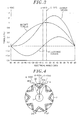
- Fig. 3 is a graph representing torque curves available in the electric machine of the first embodiment.
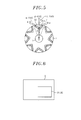
- the IPM rotating electric machine of the present embodiment is used as a drive motor 91 or a generator 92 in industrial energy-saving machines 9, e.g., a motor vehicle (such as a hybrid car, a fuel cell car or an electric vehicle), a lifting machine (such as a crane, a hoist, an elevator or a three-dimensional parking facility), a fluid machine (such as a compressor, a blower or a pump for pneumatic or hydraulic purposes) and a processing machine (such as a semiconductor manufacturing apparatus or a machine tool) as shown in Fig. 6 .
- a motor vehicle such as a hybrid car, a fuel cell car or an electric vehicle
- a lifting machine such as a crane, a hoist, an elevator or a three-dimensional parking facility
- a fluid machine such as a compressor, a blower or a pump for pneumatic or hydraulic purposes
- a processing machine such as a semiconductor manufacturing apparatus or a machine tool
- the IPM rotating electric machine of the present embodiment is also used as a drive motor for driving wheels of the motor vehicle
- the electric machine of the present embodiment includes a stator 100 and a rotor 200.
- the stator 100 includes a stator core 101 and stator windings 102 and surrounds the outer circumference of the rotor 200.
- the stator windings 102 are provided within the slots formed in the stator core 101.
- the rotor 200 includes a shaft 1, a rotor core 2, first permanent magnets 31 and second permanent magnets 32.
- the rotor core 2 is fixed to the outer circumference of the shaft 1.
- V-shaped magnet holes 41 each of which has a first wing portion 41a, a second wing portion 41b and an apex pointing toward the rotation axis O of the shaft 1, are formed in the rotor core 2.
- Each of the first permanent magnets 31 is arranged in the first wing portion 41a of each of the magnet holes 41.
- Each of the second permanent magnets 32 is positioned in the second wing portion 41b of each of the magnet holes 41.
- the first permanent magnets 31 and the second permanent magnets 32 have rectangular shapes and they are arranged so that each pair of the first and the second permanent magnet 31 and 32 defines first and second sides of the letter V whose apex points toward the rotation axis O. If a straight line extending radially to interconnect the rotation axis O and the apex of each of the V-shaped magnet holes 41 is assumed to be an A-axis, each of the first permanent magnets 31 and each of the second permanent magnets 32 corresponding to each other are arranged with the A-axis interposed therebetween.
- the first permanent magnet 31 and the second permanent magnet 32 corresponding to each other forms a single magnetic pole 51.
- a desired number of magnetic poles 5 are arranged in the rotor core 2 at an equal interval along the circumferential direction. In the embodiment illustrated in Fig. 2 , the number of the magnetic poles 51 is eight.
- the energy product of the first permanent magnets 31 is set equal to the energy product of the second permanent magnets 32.
- the length (thickness) 31t of each of the first permanent magnets 31 in the direction perpendicular to the extension direction of the first side of the letter V defined by the first permanent magnet 31 is set equal to the length (thickness) 32t of each of the second permanent magnets 32 in the direction perpendicular to the extension direction of the second side of the letter V defined by the second permanent magnet 32.
- the length (width) 31w of each of the first permanent magnets 31 in the direction parallel to the extension direction of the first side of the letter V defined by the first permanent magnet 31 is set smaller than the length (width) 32w of each of the second permanent magnets 32 in the direction parallel to the extension direction of the second side of the letter V defined by the second permanent magnet 32.
- Each of the first permanent magnets 31 and each of the second permanent magnets 32 corresponding to each other are arranged to satisfy the relationship of ⁇ 2> ⁇ 1, where ⁇ 1 denotes the angle between the long side of the first permanent magnet 31 and the A-axis and ⁇ 2 denotes the angle between the long side of the second permanent magnet 32 and the A-axis.
- Fig. 7 is a section view showing a comparative IPM rotating electric machine. The section shown in Fig. 7 is taken along a plane perpendicular to the rotation axis of a rotor.
- V-shaped magnet holes 4 whose apex points toward the rotation axis O of the shaft 1 are formed in a rotor core 2.
- Permanent magnets 3 are arranged in the respective portions making up the V-shaped wings of the magnet holes 4 (namely, the respective wing portions of the magnet holes 4).
- the two permanent magnets 3 accommodated in the wings of each of the V-shaped magnet holes 4 are arranged symmetrically to each other with respect to the A-axis and define together first and second sides of the letter V whose apex points toward the rotation axis O. Accordingly, on the sectional plane, the two permanent magnets 3 are equal to each other in the length (width) parallel to the corresponding side of the letter V, the length (thickness) perpendicular to the corresponding side of the letter V and the angle relative to the A-axis.
- the magnetic flux of basic wave in the gaps generated by the magnetic poles 5 is distributed in the form of a sine wave whose peak lies at the A-axis.
- the A-axis coincides with the d-axis used in d-q axis control. If a position on the rotor electrically phase-shifted 90 degrees from the A-axis is assumed to be a B-axis, the B-axis coincides the q-axis used in the d-q axis control and also coincides with the straight line that interconnects the midpoint between the circumferentially adjoining magnetic poles 5 and the rotation axis O.
- Fig. 7 represents torque curves available in the comparative example.
- a current iq flows through the stator winding positioned on the d-axis
- magnet torque is generated between the stator windings and the magnetic flux formed by the magnetic poles 5.
- Reluctance torque is generated if a current -id flows through the stator winding positioned on the q-axis.
- Maximum output torque can be obtained by allowing a current to flow through the stator winding arranged in the position where the resultant torque of the magnet torque and the reluctance torque becomes greatest.
- the arrangement of the first permanent magnets 31 and the second permanent magnets 32 in accordance with the present embodiment generates a deviation in the distributions of the magnetic flux formed by the first permanent magnets 31 and the second permanent magnets 32 in the gaps between the stator 100 and the rotor 200. Therefore, as illustrated in Fig. 3 , it is possible to generate a phase difference between the A-axis where the magnetic flux becomes greatest and the d-axis which is shifted from the q-axis by an electrical angle of 90 degrees, consequently shifting the A-axis toward the maximum reluctance torque side. This makes it possible to increase the output torque as can be seen in Fig. 3 as compared with the output torque of the comparative IPM rotating electric machine shown in Fig. 8 .
- first and second permanent magnets 31 and 32 have a rectangular cross-sectional shape in the embodiment shown in Figs. 1 and 2
- the present invention is not limited thereto.
- the cross-sectional shape of the first and second permanent magnets 31 and 32 may be, e.g., a square shape, an elliptical shape or an arc shape.
- the ⁇ 1 denotes the angle between the A-axis and an axis parallel to the width direction of the first permanent magnet 31
- the ⁇ 2 denotes the angle between the A-axis and an axis parallel to the width direction of the first permanent magnet 32.
- Fig. 4 is a section view showing a rotor for an IPM rotating electric machine in accordance with the second embodiment of the present invention.
- the second embodiment differs from the first embodiment in that the thickness of each of the first permanent magnets 31 (the length of each of the first permanent magnets 31 in the direction perpendicular to the extension direction of the first side of the letter V defined by the first permanent magnet 31) is set greater than the thickness of each of the second permanent magnets 32 (the length of each of the second permanent magnets 32 in the direction perpendicular to the extension direction of the second side of the letter V defined by the second permanent magnet 32).
- the same components as those of the first embodiment shown in Fig. 2 are designated by like reference numerals in Fig. 4 and redundant description thereof will be omitted.
- the first permanent magnets whose thickness is greater than that of the second permanent magnets 32 are designated by reference numeral 31a and the rotor of the second embodiment will be described with emphasis placed on the points differing from the first embodiment.
- the operating point of the first permanent magnets 31a is lower than that of the second permanent magnets 32 because the width 31w of each of the first permanent magnets 31a is set smaller than the width 32w of each of the second permanent magnets 32 as in the rotor shown in Fig. 2 . For that reason, the density of the magnetic flux formed by the first permanent magnets 31a tends to become lower than the density of the magnetic flux formed by the second permanent magnets 32. However, since the thickness 31t of the first permanent magnets 31a is set greater than the thickness 32t of the second permanent magnets 32, it is possible to increase the operating point of the first permanent magnets 31a and hence the density of the magnetic flux formed by the first permanent magnets 31a.
- Fig. 5 is a section view showing a rotor for an IPM rotating electric machine in accordance with the third embodiment of the present invention.
- the third embodiment differs from the first embodiment in that the energy product of the first permanent magnets 31 is set greater than the energy product of the second permanent magnets 32.
- the same components as those of the first embodiment shown in Fig. 2 are designated by like reference numerals in Fig. 5 and will be omitted from description.
- the first permanent magnets whose energy product is greater than that of the second permanent magnets 32 are designated by reference numeral 31b and the rotor of the third embodiment will be described with emphasis placed on the points differing from the first embodiment.
- the operating point of the first permanent magnets 31b is lower than that of the second permanent magnets 32 because the width 31w of each of the first permanent magnets 31a is set smaller than the width 32w of each of the second permanent magnets 32 as in the rotor shown in Fig. 2 . For that reason, the density of the magnetic flux formed by the first permanent magnets 31b tends to become lower than the density of the magnetic flux formed by the second permanent magnets 32. However, since the product of energy of the first permanent magnets 31b is set greater than the product of energy of the second permanent magnets 32, it is possible to increase the density of the magnetic flux formed by the first permanent magnets 31b.
- the IPM rotating electric machine of the present invention is capable of generating high output power and can be used as a drive motor or a generator in industrial energy-saving machines, e.g., a motor vehicle, a lifting machine, a fluid machine and a processing machine.
- industrial energy-saving machines e.g., a motor vehicle, a lifting machine, a fluid machine and a processing machine.
Landscapes
- Engineering & Computer Science (AREA)
- Power Engineering (AREA)
- Chemical & Material Sciences (AREA)
- Combustion & Propulsion (AREA)
- Transportation (AREA)
- Mechanical Engineering (AREA)
- Permanent Field Magnets Of Synchronous Machinery (AREA)
- Iron Core Of Rotating Electric Machines (AREA)
Abstract
A rotor includes a rotor core; and first permanent magnets and second permanent magnets arranged in the rotor core so that, on a cross-sectional plane of the rotor core perpendicular to the rotation axis thereof, the first and second magnets corresponding to each other define the letter V having an apex pointing toward the rotation axis. The first and second magnets corresponding to each other are arranged so that a straight line interconnecting the rotation axis and the apex of the letter V is interposed therebetween, an angle of the first magnet relative to the straight line being smaller than that of the second magnet relative to the straight line, a width of the first magnet in the direction parallel to the first side of the letter V being smaller than that of the second magnet in the direction parallel to the second side of the letter V.
Description
- The present invention relates to a rotor for use in an IPM (interior permanent magnet) rotating electric machine and an IPM rotating electric machine provided with the rotor. Further, the present invention relates to a motor vehicle, a lifting machine, a fluid machine and a processing machine provided with the IPM rotating electric machine.
- Japanese Patent Application Publication No.
2006-254629 - In such a conventional IPM rotating electric machine, a plurality of permanent magnets are arranged so that two corresponding permanent magnets define the letter V whose apex points toward the rotation axis of the rotor. The two corresponding permanent magnets form a single magnetic pole. The two corresponding permanent magnets have a same shape and are arranged symmetrically to each other with respect to a straight line radially extending through the apex of the letter V and the rotation axis. In, other words, in a section view perpendicular to the rotation axis, the two corresponding permanent magnets are equal to each other in the length (width) parallel to the corresponding side of the letter V, the length (thickness) perpendicular to the corresponding side of the letter V and the angle with respect to the straight line.
- With the magnet arrangement employed in the conventional IPM rotating electric machine, however, the volume of the rotor core is reduced if one attempts to increase the magnet torque by increasing the input volume of the permanent magnets in an effort to make the output torque greater. This tends to reduce the reluctance torque. In order to increase the reluctance torque, there is a need to increase the volume of the rotor core. The increase in the volume of the rotor core, however, would result in a decrease in the input volume of the permanent magnets, eventually reducing the magnet torque.
- As mentioned above, the increase of the magnet torque accomplished by increasing the input volume of the permanent magnets has a tradeoff relationship with the increase of the reluctance torque accomplished by increasing the volume of the rotor core. For that reason, in the conventional IPM rotating electric machine, it is difficult to increase the output torque thereof.
- It is, therefore, an object of the present invention to provide a rotor for use in an IPM rotating electric machine capable of increasing the output torque, the IPM rotating electric machine provided with the rotor, and a motor vehicle, a lifting machine, a fluid machine and a processing machine provided with the IPM rotating electric machine.
- In accordance with a first aspect of the present invention, there is provided a rotor including: a rotor core having a rotation axis; and first permanent magnets and second permanent magnets arranged in the rotor core so that, on a cross-sectional plane of the rotor core perpendicular to the rotation axis, each of the first permanent magnets and each of the second permanent magnets corresponding to each other define the letter V having a first side, a second side and an apex pointing toward the rotation axis, the first side of the letter V being defined by each of the first permanent magnets, the second side of the letter V being defined by each of the second permanent magnets, each of the first permanent magnets and each of the second permanent magnets corresponding to each other cooperating to form a single magnetic pole. Each of the first permanent magnets and each of the second permanent magnets corresponding to each other are arranged on the cross-sectional plane of the rotor core so that a straight line interconnecting the rotation axis and the apex of the letter V is interposed therebetween, an angle of each of the first permanent magnets relative to the straight line being smaller than an angle of each of the second permanent magnets relative to the straight line, a width of each of the first permanent magnets in the direction parallel to the extension direction of the first side of the letter V being smaller than a width of each of the second permanent magnets in the direction parallel to the extension direction of the second side of the letter V.
- On the cross-sectional plane of the rotor core, the thickness of each of the first permanent magnets in the direction perpendicular to the extension direction of the first side of the letter V may be greater than the thickness of each of the second permanent magnets in the direction perpendicular to the extension direction of the second wing of the letter V. Further, the energy product of the first permanent magnets may be greater than the energy product of the second permanent magnets.
- In accordance with a second aspect of the present invention, there is provided an IPM (interior permanent magnet) rotating electric machine including: a stator core; stator windings provided in the stator core; a rotor core having a rotation axis and an outer circumference surrounded by the stator core; and first permanent magnets and second permanent magnets arranged in the rotor core so that, on a cross-sectional plane of the rotor core perpendicular to the rotation axis, each of the first permanent magnets and each of the second permanent magnets corresponding to each other define the letter V having a first side, a second side and an apex pointing toward the rotation axis, the first side of the letter V being defined by each of the first permanent magnets, the second side of the letter V being defined by each of the second permanent magnets, each of the first permanent magnets and each of the second permanent magnets corresponding to each other cooperating to form a single magnetic pole. Each of the first permanent magnets and each of the second permanent magnets corresponding to each other are arranged on the cross-sectional plane of the rotor core so that a straight line interconnecting the rotation axis and the apex of the letter V is interposed therebetween, an angle of each of the first permanent magnets relative to the straight line being smaller than an angle of each of the second permanent magnets relative to the straight line, a width of each of the first permanent magnets in the direction parallel to the extension direction of the first side of the letter V being smaller than a width of each of the second permanent magnets in the direction parallel to the extension direction of the second side of the letter V.
- In accordance with a third aspect of the present invention, there is provided a motor vehicle in which the IPM rotating electric machine is used as a drive motor.
- In accordance with a fourth aspect of the present invention, there is provided a motor vehicle in which the IPM rotating electric machine is used as a generator.
- In accordance with a fifth aspect of the present invention, there is provided a lifting machine in which the IPM rotating electric machine is used as a drive motor.
- In accordance with a sixth aspect of the present invention, there is provided a fluid machine in which the IPM rotating electric machine is used as a drive motor.
- In accordance with a seventh aspect of the present invention, there is provided a processing machine in which the IPM rotating electric machine is used as a drive motor.
- In accordance with the present invention, it is possible to provide a rotor for use in an IPM rotating electric machine capable of increasing the output torque, the IPM rotating electric machine provided with the rotor, and a motor vehicle, a lifting machine, a fluid machine and a processing machine provided with the IPM rotating electric machine.
- The above and other objects and features of the present invention will become apparent from the following description of embodiments, given in conjunction with the accompanying drawings, in which:
-
Fig. 1 is a section view showing an IPM rotating electric machine in accordance with a first embodiment of the present invention; -
Fig. 2 is a section view showing a rotor employed in the electric machine of the first embodiment; -
Fig. 3 is a graph representing torque curves available in the electric machine of the first embodiment; -
Fig. 4 is a section view showing a rotor for use in an IPM rotating electric machine in accordance with a second embodiment of the present invention; -
Fig. 5 is a section view showing a rotor for use in an IPM rotating electric machine in accordance with a third embodiment of the present invention; -
Fig. 6 is a block diagram schematically showing an industrial energy-saving machine including the IPM rotating electric machine; -
Fig. 7 is a section view showing a rotor used in a comparative IPM rotating electric machine; and -
Fig. 8 is a graph representing torque curves available in the comparative IPM rotating electric machine. - Embodiments of the present invention will now be described with reference to the accompanying drawings which form a part hereof.
-
Fig. 1 is a section view showing an IPM (interior permanent magnet) rotating electric machine in accordance with the first embodiment of the present invention.Fig. 2 is a section view showing a rotor employed in the electric machine of the first embodiment. The sections shown inFigs. 1 and 2 are taken along a plane perpendicular to the rotation axis of the rotor.Fig. 3 is a graph representing torque curves available in the electric machine of the first embodiment. - The IPM rotating electric machine of the present embodiment is used as a drive motor 91 or a generator 92 in industrial energy-saving
machines 9, e.g., a motor vehicle (such as a hybrid car, a fuel cell car or an electric vehicle), a lifting machine (such as a crane, a hoist, an elevator or a three-dimensional parking facility), a fluid machine (such as a compressor, a blower or a pump for pneumatic or hydraulic purposes) and a processing machine (such as a semiconductor manufacturing apparatus or a machine tool) as shown inFig. 6 . - Further, the IPM rotating electric machine of the present embodiment is also used as a drive motor for driving wheels of the motor vehicle
- Referring to
Fig. 1 , the electric machine of the present embodiment includes astator 100 and arotor 200. Thestator 100 includes astator core 101 andstator windings 102 and surrounds the outer circumference of therotor 200. Thestator windings 102 are provided within the slots formed in thestator core 101. - As shown in
Fig. 2 , therotor 200 includes ashaft 1, arotor core 2, firstpermanent magnets 31 and secondpermanent magnets 32. Therotor core 2 is fixed to the outer circumference of theshaft 1. V-shaped magnet holes 41, each of which has afirst wing portion 41a, asecond wing portion 41b and an apex pointing toward the rotation axis O of theshaft 1, are formed in therotor core 2. Each of the firstpermanent magnets 31 is arranged in thefirst wing portion 41a of each of the magnet holes 41. Each of the secondpermanent magnets 32 is positioned in thesecond wing portion 41b of each of the magnet holes 41. On the sectional plane of therotor core 2 perpendicular to the rotation axis O, the firstpermanent magnets 31 and the secondpermanent magnets 32 have rectangular shapes and they are arranged so that each pair of the first and the secondpermanent magnet permanent magnets 31 and each of the secondpermanent magnets 32 corresponding to each other are arranged with the A-axis interposed therebetween. The firstpermanent magnet 31 and the secondpermanent magnet 32 corresponding to each other forms a singlemagnetic pole 51. A desired number ofmagnetic poles 5 are arranged in therotor core 2 at an equal interval along the circumferential direction. In the embodiment illustrated inFig. 2 , the number of themagnetic poles 51 is eight. - In the present embodiment, the energy product of the first
permanent magnets 31 is set equal to the energy product of the secondpermanent magnets 32. On the sectional plane of therotor core 2, the length (thickness) 31t of each of the firstpermanent magnets 31 in the direction perpendicular to the extension direction of the first side of the letter V defined by the firstpermanent magnet 31 is set equal to the length (thickness) 32t of each of the secondpermanent magnets 32 in the direction perpendicular to the extension direction of the second side of the letter V defined by the secondpermanent magnet 32. - On the sectional plane of the
rotor core 2, the length (width) 31w of each of the firstpermanent magnets 31 in the direction parallel to the extension direction of the first side of the letter V defined by the firstpermanent magnet 31 is set smaller than the length (width) 32w of each of the secondpermanent magnets 32 in the direction parallel to the extension direction of the second side of the letter V defined by the secondpermanent magnet 32. Each of the firstpermanent magnets 31 and each of the secondpermanent magnets 32 corresponding to each other are arranged to satisfy the relationship of θ2>θ1, where θ1 denotes the angle between the long side of the firstpermanent magnet 31 and the A-axis and θ2 denotes the angle between the long side of the secondpermanent magnet 32 and the A-axis. - Here, a comparative example will be described with reference to
Figs. 7 and8 .Fig. 7 is a section view showing a comparative IPM rotating electric machine. The section shown inFig. 7 is taken along a plane perpendicular to the rotation axis of a rotor. - As shown in
Fig. 7 , in the comparative example, V-shaped magnet holes 4 whose apex points toward the rotation axis O of theshaft 1 are formed in arotor core 2.Permanent magnets 3 are arranged in the respective portions making up the V-shaped wings of the magnet holes 4 (namely, the respective wing portions of the magnet holes 4). If a straight line extending radially to interconnect the rotation axis O (rotation center) and the apex of each of the V-shaped magnet holes 4 is assumed to be an A-axis, the twopermanent magnets 3 accommodated in the wings of each of the V-shaped magnet holes 4 are arranged symmetrically to each other with respect to the A-axis and define together first and second sides of the letter V whose apex points toward the rotation axis O. Accordingly, on the sectional plane, the twopermanent magnets 3 are equal to each other in the length (width) parallel to the corresponding side of the letter V, the length (thickness) perpendicular to the corresponding side of the letter V and the angle relative to the A-axis. - In case of the configuration noted above, the magnetic flux of basic wave in the gaps generated by the
magnetic poles 5 is distributed in the form of a sine wave whose peak lies at the A-axis. The A-axis coincides with the d-axis used in d-q axis control. If a position on the rotor electrically phase-shifted 90 degrees from the A-axis is assumed to be a B-axis, the B-axis coincides the q-axis used in the d-q axis control and also coincides with the straight line that interconnects the midpoint between the circumferentially adjoiningmagnetic poles 5 and the rotation axis O. -
Fig. 7 represents torque curves available in the comparative example. In the comparative example, if a current iq flows through the stator winding positioned on the d-axis, magnet torque is generated between the stator windings and the magnetic flux formed by themagnetic poles 5. Reluctance torque is generated if a current -id flows through the stator winding positioned on the q-axis. Maximum output torque can be obtained by allowing a current to flow through the stator winding arranged in the position where the resultant torque of the magnet torque and the reluctance torque becomes greatest. - On the other hand, the arrangement of the first
permanent magnets 31 and the secondpermanent magnets 32 in accordance with the present embodiment generates a deviation in the distributions of the magnetic flux formed by the firstpermanent magnets 31 and the secondpermanent magnets 32 in the gaps between thestator 100 and therotor 200. Therefore, as illustrated inFig. 3 , it is possible to generate a phase difference between the A-axis where the magnetic flux becomes greatest and the d-axis which is shifted from the q-axis by an electrical angle of 90 degrees, consequently shifting the A-axis toward the maximum reluctance torque side. This makes it possible to increase the output torque as can be seen inFig. 3 as compared with the output torque of the comparative IPM rotating electric machine shown inFig. 8 . - While the first and second
permanent magnets Figs. 1 and 2 , the present invention is not limited thereto. Alternatively, the cross-sectional shape of the first and secondpermanent magnets permanent magnet 31 and the θ2 denotes the angle between the A-axis and an axis parallel to the width direction of the firstpermanent magnet 32. -
Fig. 4 is a section view showing a rotor for an IPM rotating electric machine in accordance with the second embodiment of the present invention. The second embodiment differs from the first embodiment in that the thickness of each of the first permanent magnets 31 (the length of each of the firstpermanent magnets 31 in the direction perpendicular to the extension direction of the first side of the letter V defined by the first permanent magnet 31) is set greater than the thickness of each of the second permanent magnets 32 (the length of each of the secondpermanent magnets 32 in the direction perpendicular to the extension direction of the second side of the letter V defined by the second permanent magnet 32). The same components as those of the first embodiment shown inFig. 2 are designated by like reference numerals inFig. 4 and redundant description thereof will be omitted. Hereinafter, the first permanent magnets whose thickness is greater than that of the secondpermanent magnets 32 are designated byreference numeral 31a and the rotor of the second embodiment will be described with emphasis placed on the points differing from the first embodiment. - The operating point of the first
permanent magnets 31a is lower than that of the secondpermanent magnets 32 because thewidth 31w of each of the firstpermanent magnets 31a is set smaller than thewidth 32w of each of the secondpermanent magnets 32 as in the rotor shown inFig. 2 . For that reason, the density of the magnetic flux formed by the firstpermanent magnets 31a tends to become lower than the density of the magnetic flux formed by the secondpermanent magnets 32. However, since thethickness 31t of the firstpermanent magnets 31a is set greater than thethickness 32t of the secondpermanent magnets 32, it is possible to increase the operating point of the firstpermanent magnets 31a and hence the density of the magnetic flux formed by the firstpermanent magnets 31a. This makes it possible to generate a greater deviation in the distributions of the magnetic flux formed by the firstpermanent magnets 31a and the secondpermanent magnets 32 in the gaps between thestator 100 and therotor 200 as compared with the first embodiment. As a result, it is possible to further increase the phase difference between the A-axis and the d-axis, thereby further increasing the output torque as compared with the first embodiment. -
Fig. 5 is a section view showing a rotor for an IPM rotating electric machine in accordance with the third embodiment of the present invention. The third embodiment differs from the first embodiment in that the energy product of the firstpermanent magnets 31 is set greater than the energy product of the secondpermanent magnets 32. The same components as those of the first embodiment shown inFig. 2 are designated by like reference numerals inFig. 5 and will be omitted from description. Hereinafter, the first permanent magnets whose energy product is greater than that of the secondpermanent magnets 32 are designated byreference numeral 31b and the rotor of the third embodiment will be described with emphasis placed on the points differing from the first embodiment. - The operating point of the first
permanent magnets 31b is lower than that of the secondpermanent magnets 32 because thewidth 31w of each of the firstpermanent magnets 31a is set smaller than thewidth 32w of each of the secondpermanent magnets 32 as in the rotor shown inFig. 2 . For that reason, the density of the magnetic flux formed by the firstpermanent magnets 31b tends to become lower than the density of the magnetic flux formed by the secondpermanent magnets 32. However, since the product of energy of the firstpermanent magnets 31b is set greater than the product of energy of the secondpermanent magnets 32, it is possible to increase the density of the magnetic flux formed by the firstpermanent magnets 31b. This makes it possible to generate a greater deviation in the distributions of the magnetic flux formed by the firstpermanent magnets 31b and the secondpermanent magnets 32 in the gaps between thestator 100 and therotor 200 as compared with the first embodiment. As a result, it is possible to further increase the phase difference between the A-axis and the d-axis, thereby increasing the output torque as compared with the first embodiment. - In the embodiments described above, the second embodiment and the third embodiment have been separately described, the combination thereof may be possible.
- The IPM rotating electric machine of the present invention is capable of generating high output power and can be used as a drive motor or a generator in industrial energy-saving machines, e.g., a motor vehicle, a lifting machine, a fluid machine and a processing machine.
- While the invention has been shown and described with respect to the embodiments, it will be understood by those skilled in the art that various changes and modification may be made without departing from the scope of the invention as defined in the following claims.
Claims (11)
- A rotor, comprising:a rotor core having a rotation axis; andfirst permanent magnets and second permanent magnets arranged in the rotor core so that, on a cross-sectional plane of the rotor core perpendicular to the rotation axis, each of the first permanent magnets and each of the second permanent magnets corresponding to each other define the letter V having a first side, a second side and an apex pointing toward the rotation axis, the first side of the letter V being defined by each of the first permanent magnets, the second side of the letter V being defined by each of the second permanent magnets, each of the first permanent magnets and each of the second permanent magnets corresponding to each other cooperating to form a single magnetic pole,wherein each of the first permanent magnets and each of the second permanent magnets corresponding to each other are arranged on the cross-sectional plane of the rotor core so that a straight line interconnecting the rotation axis and the apex of the letter V is interposed therebetween, an angle of each of the first permanent magnets relative to the straight line being smaller than an angle of each of the second permanent magnets relative to the straight line, a width of each of the first permanent magnets in the direction parallel to the extension direction of the first side of the letter V being smaller than a width of each of the second permanent magnets in the direction parallel to the extension direction of the second side of the letter V.
- The rotor of claim 1, wherein, on the cross-sectional plane of the rotor core, the thickness of each of the first permanent magnets in the direction perpendicular to the extension direction of the first side of the letter V is greater than the thickness of each of the second permanent magnets in the direction perpendicular to the extension direction of the second wing of the letter V.
- The rotor of claim 1 or 2, wherein the energy product of the first permanent magnets is greater than the energy product of the second permanent magnets.
- An IPM (interior permanent magnet) rotating electric machine, comprising:a stator core;stator windings provided in the stator core; andthe rotor of any one of claims 1 to 3,wherein an outer circumference of the rotor core is surrounded by the stator core.
- The machine of claim 4, wherein, on the cross-sectional plane of the rotor core, the thickness of each of the first permanent magnets in the direction perpendicular to the extension direction of the first side of the letter V being greater than the thickness of each of the second permanent magnets in the direction perpendicular to the extension direction of the second side of the letter V.
- The machine of claim 4 or 5, wherein the energy product of the first permanent magnets is greater than the energy product of the second permanent magnets.
- A motor vehicle comprising the IPM rotating electric machine of any one of claims 4 to 6, wherein the IPM rotating electric machine is a drive motor of the motor vehicle.
- A motor vehicle comprising the IPM rotating electric machine of any one of claims 4 to 6, wherein the IPM rotating electric machine is a generator of the motor vehicle.
- A lifting machine comprising the IPM rotating electric machine of any one of claims 4 to 6, wherein the IPM rotating electric machine is a drive motor of the lifting machine.
- A fluid machine comprising the IPM rotating electric machine of any one of claims 4 to 6, wherein the IPM rotating electric machine is a drive motor of the fluid machine.
- A processing machine comprising the IPM rotating electric machine of any one of claims 4 to 6, wherein the IPM rotating electric machine is a drive motor of the processing machine.
Applications Claiming Priority (1)
| Application Number | Priority Date | Filing Date | Title |
|---|---|---|---|
| JP2010006278 | 2010-01-14 |
Publications (1)
| Publication Number | Publication Date |
|---|---|
| EP2346145A2 true EP2346145A2 (en) | 2011-07-20 |
Family
ID=43569295
Family Applications (1)
| Application Number | Title | Priority Date | Filing Date |
|---|---|---|---|
| EP11150484A Withdrawn EP2346145A2 (en) | 2010-01-14 | 2011-01-10 | Permanent magnet rotor of an electrical machine |
Country Status (5)
| Country | Link |
|---|---|
| US (2) | US8319387B2 (en) |
| EP (1) | EP2346145A2 (en) |
| JP (1) | JP2011167055A (en) |
| KR (1) | KR20110083556A (en) |
| CN (1) | CN102130523A (en) |
Families Citing this family (19)
| Publication number | Priority date | Publication date | Assignee | Title |
|---|---|---|---|---|
| JP2011167055A (en) * | 2010-01-14 | 2011-08-25 | Yaskawa Electric Corp | Rotor of permanent magnet type synchronous rotating electric machine, the permanent magnet type synchronous rotating electric machine, and vehicle, elevator, fluid machine or processing machine using the permanent magnet type synchronous rotating electric machine |
| CN103166344A (en) * | 2011-12-09 | 2013-06-19 | 安徽明腾永磁机电设备有限公司 | Rotor punching sheet for permanent magnet motor and rotor |
| KR101940755B1 (en) | 2012-01-16 | 2019-01-21 | 삼성전자 주식회사 | Rotor and electric motor comprising the same |
| WO2013141323A1 (en) * | 2012-03-23 | 2013-09-26 | 三菱重工オートモーティブサーマルシステムズ株式会社 | Motor and electric compressor using same |
| KR101321279B1 (en) * | 2012-04-19 | 2013-10-28 | 삼성전기주식회사 | Rotor assembly |
| JP5944267B2 (en) * | 2012-08-10 | 2016-07-05 | アイチエレック株式会社 | Rotor and electric motor |
| KR20140028737A (en) * | 2012-08-30 | 2014-03-10 | 현대모비스 주식회사 | Rotator for high power motor |
| ES2705549T3 (en) * | 2013-06-20 | 2019-03-25 | Otis Elevator Co | Electric machine that has a rotor with permanent magnets inclined |
| US10205359B2 (en) | 2013-11-18 | 2019-02-12 | Steering Solutions Ip Holding Corporation | Low cost permanent magnet motor for an electric power steering system |
| JP2015133825A (en) * | 2014-01-14 | 2015-07-23 | 株式会社ジェイテクト | Rotor for rotating electrical machines |
| US9979243B2 (en) * | 2014-11-18 | 2018-05-22 | Steering Solutions Ip Holding Corporation | Low cost injection molded buried permanent magnet motor for an electric power steering system |
| CN104767338B (en) * | 2015-03-01 | 2017-06-27 | 江苏大学 | A kind of square angle approach type magneto |
| CN107359716A (en) * | 2017-07-12 | 2017-11-17 | 中国北方车辆研究所 | A kind of mixed excitation electric machine rotor |
| TWM576750U (en) | 2017-07-25 | 2019-04-11 | 美商米沃奇電子工具公司 | Electrical composition, electric device system, battery pack, electric motor, motor assembly and electric motor assembly |
| WO2019049392A1 (en) * | 2017-09-11 | 2019-03-14 | 株式会社 東芝 | Electric rotating machine |
| DE112019003638T5 (en) * | 2018-07-19 | 2021-04-29 | Mitsubishi Electric Corporation | ROTATING ELECTRIC MACHINE |
| KR102654530B1 (en) * | 2018-12-27 | 2024-04-03 | 현대자동차주식회사 | Interior permanent magnet motor and rotator including thereof |
| EP3917708A4 (en) | 2019-02-18 | 2022-11-30 | Milwaukee Electric Tool Corporation | IMPACT TOOL |
| KR102590333B1 (en) * | 2021-05-21 | 2023-10-19 | 한국전자기술연구원 | Rotor Skew Structure for Reducing Cogging Torque and Rotor Skew Method for Reducing Cogging Torque |
Citations (1)
| Publication number | Priority date | Publication date | Assignee | Title |
|---|---|---|---|---|
| JP2006254629A (en) | 2005-03-11 | 2006-09-21 | Toyota Motor Corp | Rotating electric machine rotor, rotating electric machine, vehicle drive device |
Family Cites Families (20)
| Publication number | Priority date | Publication date | Assignee | Title |
|---|---|---|---|---|
| JP3607137B2 (en) * | 1999-10-21 | 2005-01-05 | アイチエレック株式会社 | Permanent magnet embedded rotor |
| JP3787756B2 (en) * | 2000-08-29 | 2006-06-21 | 株式会社日立製作所 | Permanent magnet rotating electric machine |
| US6917133B2 (en) * | 2000-08-29 | 2005-07-12 | Hitachi, Ltd. | Air conditioner having permanent magnet rotating electric machine |
| JP4070673B2 (en) * | 2003-07-31 | 2008-04-02 | 株式会社東芝 | Reluctance rotor |
| JP2005073450A (en) * | 2003-08-27 | 2005-03-17 | Matsushita Electric Ind Co Ltd | Motor generator |
| JP4449035B2 (en) * | 2004-03-10 | 2010-04-14 | 日立オートモティブシステムズ株式会社 | Permanent magnet rotating electric machine for electric vehicles |
| US20080258573A1 (en) * | 2005-03-11 | 2008-10-23 | Toyota Jidosha Kabushiki Kaisha | Rotor of Rotating Electric Machine, Rotating Electric Machine and Vehicle Drive Apparatus |
| JP4815967B2 (en) * | 2005-09-21 | 2011-11-16 | トヨタ自動車株式会社 | Permanent magnet rotating electric machine |
| JP4815204B2 (en) * | 2005-12-01 | 2011-11-16 | アイチエレック株式会社 | Permanent magnet rotating machine and compressor |
| US7719153B2 (en) * | 2005-12-21 | 2010-05-18 | Ut-Battelle, Llc | Permanent magnet machine and method with reluctance poles and non-identical PM poles for high density operation |
| JP2007306735A (en) * | 2006-05-12 | 2007-11-22 | Yaskawa Electric Corp | Permanent magnet motor |
| SE530697C2 (en) * | 2006-12-19 | 2008-08-19 | Bae Systems Haegglunds Ab | Rotor for an electric motor, rotor plates for the construction of the rotor, and an electric motor with such a rotor |
| JP4404223B2 (en) * | 2007-03-20 | 2010-01-27 | 株式会社安川電機 | Electromagnetic steel sheet forming body, electromagnetic steel sheet laminate, permanent magnet type synchronous rotating electric machine equipped with the same, permanent magnet type synchronous rotating electric machine, vehicle using the rotating electric machine, elevator, fluid machine, processing machine |
| JP5100169B2 (en) * | 2007-03-26 | 2012-12-19 | 株式会社東芝 | Permanent magnet type rotating electric machine and permanent magnet motor drive system |
| JP2007300796A (en) * | 2007-07-17 | 2007-11-15 | Aichi Elec Co | Rotor for permanent magnet type motor |
| US7808143B2 (en) * | 2007-10-24 | 2010-10-05 | Rechi Precision Co., Ltd. | Permanent magnet motor |
| JP2009268204A (en) * | 2008-04-23 | 2009-11-12 | Toyota Motor Corp | Rotor for ipm motor, and ipm motor |
| JP5361260B2 (en) * | 2008-06-20 | 2013-12-04 | 株式会社東芝 | Permanent magnet rotary electric machine |
| US20100117475A1 (en) * | 2008-11-11 | 2010-05-13 | Ford Global Technologies, Llc | Permanent Magnet Machine with Offset Pole Spacing |
| JP2011167055A (en) * | 2010-01-14 | 2011-08-25 | Yaskawa Electric Corp | Rotor of permanent magnet type synchronous rotating electric machine, the permanent magnet type synchronous rotating electric machine, and vehicle, elevator, fluid machine or processing machine using the permanent magnet type synchronous rotating electric machine |
-
2010
- 2010-12-02 JP JP2010268995A patent/JP2011167055A/en active Pending
-
2011
- 2011-01-10 EP EP11150484A patent/EP2346145A2/en not_active Withdrawn
- 2011-01-12 US US13/004,896 patent/US8319387B2/en not_active Expired - Fee Related
- 2011-01-12 CN CN2011100060066A patent/CN102130523A/en active Pending
- 2011-01-13 KR KR1020110003692A patent/KR20110083556A/en not_active Ceased
-
2012
- 2012-10-26 US US13/661,128 patent/US8427023B2/en not_active Expired - Fee Related
Patent Citations (1)
| Publication number | Priority date | Publication date | Assignee | Title |
|---|---|---|---|---|
| JP2006254629A (en) | 2005-03-11 | 2006-09-21 | Toyota Motor Corp | Rotating electric machine rotor, rotating electric machine, vehicle drive device |
Also Published As
| Publication number | Publication date |
|---|---|
| KR20110083556A (en) | 2011-07-20 |
| CN102130523A (en) | 2011-07-20 |
| US8427023B2 (en) | 2013-04-23 |
| US8319387B2 (en) | 2012-11-27 |
| US20130043755A1 (en) | 2013-02-21 |
| US20110169364A1 (en) | 2011-07-14 |
| JP2011167055A (en) | 2011-08-25 |
Similar Documents
| Publication | Publication Date | Title |
|---|---|---|
| EP2346145A2 (en) | Permanent magnet rotor of an electrical machine | |
| US8536748B2 (en) | Permanent magnet machine with different pole arc angles | |
| US8120223B2 (en) | Permanent magnet machine with offset pole spacing | |
| CN102782990B (en) | Rotating electrical machine | |
| US8878410B2 (en) | Rotor with reinforcing portions for an electric rotating machine | |
| US7915780B2 (en) | Laminated spiral core, dynamo-electric-machine rotor provided therewith, and dynamo-electric machine | |
| CN104937815A (en) | Permanent-magnet-type rotating electric mechanism | |
| CN108667176B (en) | IPM rotor and method for manufacturing magnet for IPM rotor | |
| EP3198708B1 (en) | Reluctance assisted external rotor pmsm | |
| WO2018037529A1 (en) | Rotary electric machine | |
| CN113364157B (en) | Stator core assembly, stator assembly and motor | |
| US7482724B2 (en) | Ipm electric rotating machine | |
| CN115378158A (en) | Electric machine | |
| CN210629214U (en) | Rotor structure and permanent magnet synchronous motor | |
| CN113853724A (en) | Four-pole synchronous reluctance motor | |
| CN113169608B (en) | Rotor for an electric machine with permanent magnet excitation having a support structure | |
| Ban et al. | Metamodel-based design and optimization of a spoke-type interior permanent magnet machine for a vehicle traction application | |
| JP2014082836A (en) | Rotor and rotary electric machine having the same | |
| EP3826145B1 (en) | Rotary electric machine, rotary electric motor drive system, and electric vehicle | |
| JP2007252077A (en) | Magnet structure | |
| JP2021136754A (en) | How to set the magnet position of the rotor of a rotary electric machine | |
| CN217769644U (en) | Motor rotor and driving motor | |
| CN120226232A (en) | Rotating electric machines | |
| JP2021125971A (en) | Rotating electric rotor | |
| CN116897493A (en) | rotor |
Legal Events
| Date | Code | Title | Description |
|---|---|---|---|
| PUAI | Public reference made under article 153(3) epc to a published international application that has entered the european phase |
Free format text: ORIGINAL CODE: 0009012 |
|
| AK | Designated contracting states |
Kind code of ref document: A2 Designated state(s): AL AT BE BG CH CY CZ DE DK EE ES FI FR GB GR HR HU IE IS IT LI LT LU LV MC MK MT NL NO PL PT RO RS SE SI SK SM TR |
|
| AX | Request for extension of the european patent |
Extension state: BA ME |
|
| STAA | Information on the status of an ep patent application or granted ep patent |
Free format text: STATUS: THE APPLICATION HAS BEEN WITHDRAWN |
|
| 18W | Application withdrawn |
Effective date: 20131218 |