EP2346118A1 - A connector assembly - Google Patents
A connector assembly Download PDFInfo
- Publication number
- EP2346118A1 EP2346118A1 EP11151023A EP11151023A EP2346118A1 EP 2346118 A1 EP2346118 A1 EP 2346118A1 EP 11151023 A EP11151023 A EP 11151023A EP 11151023 A EP11151023 A EP 11151023A EP 2346118 A1 EP2346118 A1 EP 2346118A1
- Authority
- EP
- European Patent Office
- Prior art keywords
- latch
- assembly
- shielded housing
- lever arm
- connector
- Prior art date
- Legal status (The legal status is an assumption and is not a legal conclusion. Google has not performed a legal analysis and makes no representation as to the accuracy of the status listed.)
- Withdrawn
Links
- 230000013011 mating Effects 0.000 claims abstract description 35
- 230000007704 transition Effects 0.000 claims description 9
- 239000002184 metal Substances 0.000 claims 2
- 230000000712 assembly Effects 0.000 description 25
- 238000000429 assembly Methods 0.000 description 25
- 238000009434 installation Methods 0.000 description 3
- 239000007769 metal material Substances 0.000 description 3
- 229910000838 Al alloy Inorganic materials 0.000 description 2
- RYGMFSIKBFXOCR-UHFFFAOYSA-N Copper Chemical compound [Cu] RYGMFSIKBFXOCR-UHFFFAOYSA-N 0.000 description 2
- 229910052782 aluminium Inorganic materials 0.000 description 2
- XAGFODPZIPBFFR-UHFFFAOYSA-N aluminium Chemical compound [Al] XAGFODPZIPBFFR-UHFFFAOYSA-N 0.000 description 2
- 229910052802 copper Inorganic materials 0.000 description 2
- 239000010949 copper Substances 0.000 description 2
- 230000003993 interaction Effects 0.000 description 2
- 239000000463 material Substances 0.000 description 2
- 230000005540 biological transmission Effects 0.000 description 1
- 230000015556 catabolic process Effects 0.000 description 1
- 238000006731 degradation reaction Methods 0.000 description 1
- 238000002955 isolation Methods 0.000 description 1
- 238000000034 method Methods 0.000 description 1
- 239000010935 stainless steel Substances 0.000 description 1
- 229910001220 stainless steel Inorganic materials 0.000 description 1
Images



Classifications
-
- H—ELECTRICITY
- H01—ELECTRIC ELEMENTS
- H01R—ELECTRICALLY-CONDUCTIVE CONNECTIONS; STRUCTURAL ASSOCIATIONS OF A PLURALITY OF MUTUALLY-INSULATED ELECTRICAL CONNECTING ELEMENTS; COUPLING DEVICES; CURRENT COLLECTORS
- H01R13/00—Details of coupling devices of the kinds covered by groups H01R12/70 or H01R24/00 - H01R33/00
- H01R13/62—Means for facilitating engagement or disengagement of coupling parts or for holding them in engagement
- H01R13/627—Snap or like fastening
- H01R13/6275—Latching arms not integral with the housing
-
- H—ELECTRICITY
- H01—ELECTRIC ELEMENTS
- H01R—ELECTRICALLY-CONDUCTIVE CONNECTIONS; STRUCTURAL ASSOCIATIONS OF A PLURALITY OF MUTUALLY-INSULATED ELECTRICAL CONNECTING ELEMENTS; COUPLING DEVICES; CURRENT COLLECTORS
- H01R13/00—Details of coupling devices of the kinds covered by groups H01R12/70 or H01R24/00 - H01R33/00
- H01R13/46—Bases; Cases
- H01R13/514—Bases; Cases composed as a modular blocks or assembly, i.e. composed of co-operating parts provided with contact members or holding contact members between them
-
- H—ELECTRICITY
- H01—ELECTRIC ELEMENTS
- H01R—ELECTRICALLY-CONDUCTIVE CONNECTIONS; STRUCTURAL ASSOCIATIONS OF A PLURALITY OF MUTUALLY-INSULATED ELECTRICAL CONNECTING ELEMENTS; COUPLING DEVICES; CURRENT COLLECTORS
- H01R13/00—Details of coupling devices of the kinds covered by groups H01R12/70 or H01R24/00 - H01R33/00
- H01R13/46—Bases; Cases
- H01R13/516—Means for holding or embracing insulating body, e.g. casing, hoods
- H01R13/518—Means for holding or embracing insulating body, e.g. casing, hoods for holding or embracing several coupling parts, e.g. frames
-
- H—ELECTRICITY
- H01—ELECTRIC ELEMENTS
- H01R—ELECTRICALLY-CONDUCTIVE CONNECTIONS; STRUCTURAL ASSOCIATIONS OF A PLURALITY OF MUTUALLY-INSULATED ELECTRICAL CONNECTING ELEMENTS; COUPLING DEVICES; CURRENT COLLECTORS
- H01R13/00—Details of coupling devices of the kinds covered by groups H01R12/70 or H01R24/00 - H01R33/00
- H01R13/648—Protective earth or shield arrangements on coupling devices, e.g. anti-static shielding
- H01R13/658—High frequency shielding arrangements, e.g. against EMI [Electro-Magnetic Interference] or EMP [Electro-Magnetic Pulse]
- H01R13/6581—Shield structure
- H01R13/6585—Shielding material individually surrounding or interposed between mutually spaced contacts
- H01R13/6586—Shielding material individually surrounding or interposed between mutually spaced contacts for separating multiple connector modules
-
- H—ELECTRICITY
- H01—ELECTRIC ELEMENTS
- H01R—ELECTRICALLY-CONDUCTIVE CONNECTIONS; STRUCTURAL ASSOCIATIONS OF A PLURALITY OF MUTUALLY-INSULATED ELECTRICAL CONNECTING ELEMENTS; COUPLING DEVICES; CURRENT COLLECTORS
- H01R13/00—Details of coupling devices of the kinds covered by groups H01R12/70 or H01R24/00 - H01R33/00
- H01R13/648—Protective earth or shield arrangements on coupling devices, e.g. anti-static shielding
- H01R13/658—High frequency shielding arrangements, e.g. against EMI [Electro-Magnetic Interference] or EMP [Electro-Magnetic Pulse]
- H01R13/6581—Shield structure
- H01R13/659—Shield structure with plural ports for distinct connectors
-
- H—ELECTRICITY
- H01—ELECTRIC ELEMENTS
- H01R—ELECTRICALLY-CONDUCTIVE CONNECTIONS; STRUCTURAL ASSOCIATIONS OF A PLURALITY OF MUTUALLY-INSULATED ELECTRICAL CONNECTING ELEMENTS; COUPLING DEVICES; CURRENT COLLECTORS
- H01R2201/00—Connectors or connections adapted for particular applications
- H01R2201/04—Connectors or connections adapted for particular applications for network, e.g. LAN connectors
Definitions
- the subject matter herein relates generally to data communication systems, and more particularly, to connector assemblies for data communication systems.
- Data communication systems have many applications, including telecommunications and interconnecting computers over local area networks.
- Application demands are driving systems to have increased electrical performance while increasing the density of connectivity.
- Some known systems strive to maximize the number of contact pairs within a connector to make installation orderly and efficient.
- such systems are not without disadvantages.
- Difficulties arise in achieving desired electrical transmission performance due to interference and signal degradation, such as from cross-talk between contact pairs.
- While some systems attempt to provide electrical isolation between components by surrounding them with materials that effectively provide shielding from cross-talk, providing such shielding in a limited space while maintaining an acceptable termination and assembly process has proven problematic.
- a need remains for a communication system that achieves high transfer rates with desirable system performance and space utilization.
- a need remains for a connector assembly that may be quickly installed and removed without the need for tools.
- a connector assembly for mating with a multi-port electrical connector including a shielded housing having a plurality of discrete shielded plug chambers and a plurality of plugs received in corresponding plug chambers. Each of the plugs is shielded from one another by the shielded housing, and the plugs are configured for simultaneous mating with the multi-port electrical connector, wherein each plug is received in a different port of the electrical connector.
- the connector assembly also includes a latch assembly coupled to the shielded housing. The latch assembly engages the shielded housing and is configured to engage the multi-port electrical connector to electrically common the shielded housing and the multi-port electrical connector.
- a connector assembly for mating with a multi-port electrical connector that includes a shielded housing having a plurality of discrete shielded plug chambers and a plurality of plugs received in corresponding plug chambers. Each of the plugs are shielded from one another by the shielded housing. The plugs are configured for simultaneous mating with the multi-port electrical connector, wherein each plug is received in a different port of the electrical connector.
- the connector assembly also includes a latch assembly arranged along at least one of the sides of the shielded housing. The latch assembly has a spring latch configured to engage the electrical connector to secure the connector assembly to the electrical connector when the spring latch is in a latched position.
- the latch assembly also has a lever arm engaging the spring latch, which is actuated to move the spring latch to an unlatched position.
- the latch assembly also has a lever lock movable between a locked position and an unlocked position. The lever lock locks the lever arm in place relative to the spring latch in the locked position. The lever arm is movable when the lever lock is in the unlocked position to allow the lever arm to move the spring latch to the unlatched position.
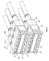
- Figure 1 is a front perspective view of a portion of a cable interconnect system illustrating a panel and a plurality of cassettes mounted to the panel.
- Figure 3 is a rear perspective view of one of the cassettes.
- Figure 4 illustrates an exemplary communication module for use with the cassette shown in Figures 1-3 .
- Figure 5 is a front perspective view of an exemplary connector assembly for mating with the cassette shown in Figures 1-3 .
- Figure 6 is an exploded view of the connector assembly shown in Figure 5 .
- Figure 7 is an exploded view of a latch assembly for the connector assembly shown in Figure 5 .
- Figure 8 is a partial cut-away view of the connector assembly illustrating the latch assembly coupled to the connector assembly.
- Figure 9 is a partial cross-sectional view of the connector assembly with the latch assembly in a locked position.
- Figure 10 is a partial cross-sectional view of the connector assembly with the latch assembly in an unlocked, latched position.
- Figure 1 is a front perspective view of a portion of a cable interconnect system 10 illustrating a panel 12 and a plurality of cassettes 18 mounted to the panel 12.
- Figure 1 also illustrates a modular plug 14 connected to one of the cassettes 18.
- the cassette 18 comprises an array of receptacles 16 for accepting or receiving the modular plug 14.
- the cassette 18 represents a multi-port electrical connector, and may be referred to hereinafter as multi-port electrical connector 18 or electrical connector 18.
- the cable interconnect system 10 is utilized to interconnect various equipment, components and/or devices to one another.
- Figure 1 schematically illustrates a first device 20 connected to the cassette 18 via a cable 22.
- the modular plug 14 is attached to the end of the cable 22.
- Figure 1 also illustrates a second device 24 connected to the cassette 18 via a cable 26, such as a multi-pair cable having multiple wire pairs.
- a multi-plug connector assembly 100 is provided at the end of each cable 26, which is connected to a back end of the cassette 18.
- the cassette 18 interconnects the first and second devices 20, 24.
- the first device 20 may be a computer located remote from the cassette 18.
- the second device 24 may be a network switch.
- the second device 24 may be located in the vicinity of the cassette 18, such as in the same equipment room, or alternatively, may be located remote from the cassette 18.
- the cable interconnect system 10 may include a support structure 28, a portion of which is illustrated in Figure 1 , for supporting the panel 12 and the cassettes 18.
- the support structure 28 may be an equipment rack of a network system.
- the panel 12 may be a patch panel that is mounted to the equipment rack. In a typical system, multiple panels 12 may be stacked within the support structure 28.
- the panels 12 may be sized to fit a standard rack specification, such as that defined in EIA-310.
- the panels 12 may have a one rack unit height, or 1U eight, of 45mm (1.75 inches).
- the panel 12 may be another type of network component used with a network system that supports cassettes 18 and/or other connector assemblies, such as interface modules, stacked jacks, or other individual modular jacks.
- the panel 12 may be a wall or other structural element of a component.
- the cable interconnect system 10 illustrated in Figure 1 is merely illustrative of an exemplary system/component for interconnecting communication cables using modular jacks and modular plugs or other types of connectors.
- the second device 24 may be mounted to the support structure 28.
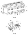
- FIG 2 is a front perspective view of a plurality of stacked cassettes 18 with the corresponding panels 12 (shown in Figure 1 ) removed illustrating a plurality of multi-plug connector assemblies 100 mated with the cassettes 18.
- the cassettes 18 may be substantially similar to the cassettes described in U.S. Patent Application No. 12/394,987 , Titled SHIELDED CASSETTE FOR A CABLE INTERCONNECT SYSTEM.
- the cassette 18 includes a front mating interface 30 and a rear mating interface 32.
- the modular plugs 14 (shown in Figure 1 ) are mated with the cassettes 18 at the front mating interface 30.
- the multi-plug connector assemblies 100 are mated with the cassettes 18 at the rear mating interface 32.
- the cassette 18 includes a plurality of receptacles 16 open at the front mating interface 30 for receiving the modular plugs 14.
- the receptacles 16 are arranged in a stacked configuration in a first row and a second row. A plurality of receptacles 16 are arranged in each of the first and second rows.
- the cassettes 18 may have more or less than twelve receptacles 16 arranged in more or less than two rows.
- Communication modules 36 are held within the cassette 18 for interfacing with the modular plugs 14 and the multi-plug connector assemblies 100.
- the communication modules 36 are exposed within the receptacles 16 for mating with the modular plugs.
- the communication modules 36 also extend to the rear mating interface 32 for interfacing with the connector assemblies 100. Data is transferred by the communication modules 36 between the modular plugs 14 and the corresponding connector assemblies 100.
- Each multi-plug connector assembly 100 may be electrically connected to more than one communication module 36.
- each connector assembly 100 is electrically connected to four communication modules 36, and thus communicate with four different modular plugs 14.
- the communication modules 36 are configured to mate with an 8 position, 8 contact (8P8C) type of plug, such as an RJ-45 plug or another copper-based modular plug type of connector at the front mating interface 30.
- the communication modules 36 may be configured to mate with different types of plugs, such as other copper based types of plugs (e.g. a quad-plug) or fiber-optic types of plugs.
- the communication modules 36 are configured to mate with a different type of plug at the rear mating interface 32, however the mating interfaces at the front and rear of the communication modules 36 may be the same in some alternative embodiments.
- the connector assemblies 100 each have latch assemblies 200 that securely couple the connector assemblies 100 to the cassettes 18.
- the cassettes 18 include catches 37 that interact with the latch assemblies 200 to secure the connector assemblies 100 to the cassettes 18.
- the latch assemblies 200 may be unlatched to remove the connector assemblies 100 from the cassettes 18.
- the latch assemblies 200 electrically common the cassettes 18 and the connector assemblies 100. When electrically commoned, the cassettes 18 and the connector assemblies 100 are at the same electrical potential.
- the latch assemblies 200 create a ground path between the connector assemblies and the cassettes 18, such as when the cassettes 18 are grounded, such as to earth ground or chassis ground.
- FIG 3 is a rear perspective view of one of the cassettes 18 illustrating the rear mating interface 32 and a portion of the communication modules 36 at the rear mating interface 32.
- the communication modules 36 are illustrated more fully in Figure 4 .
- the communication modules 36 are configured to be directly electrically connected to the connector assemblies 100 (shown in Figures 1 and 2 ).
- the cassette 18 includes a plurality of interior walls 38 that define different plug cavities 40 at the rear mating interface 32.
- the interior walls 38 define shield elements between adjacent plug cavities 40 that provide shielding between the communication modules 36 received in the corresponding plug cavities 40.
- the walls 38 may extend at least partially between the front and the rear of the cassette 18 and the walls 38 may also define the receptacles 16 (shown in Figure 2 ) at the front mating interface 30.
- the communication modules 36 at the rear mating interface 32 represent a quad-type mating interface configured to receive a quad-type plug connector therein.
- the communication modules 36 each include contacts 42.
- the contacts 42 are arranged in pairs in different quadrants of the plug cavities 40.
- Wall segments 44 divide the plug cavities 40 into quadrants, with each quadrant receiving a pair of the contacts 42.
- the wall segments 44 may provide shielding from adjacent quadrants.
- FIG. 4 illustrates the communication module 36.
- the communication module 36 includes a circuit board 50, a contact support 52, and a plurality of contacts 54 arranged as a contact set.
- the contact support 52 and the contacts 54 extend from a front side of the circuit board 50.
- the contact support 52 and the contacts 54 define a mating interface configured to mate with an RJ-45 type plug.
- the communication module 36 includes a plurality of support towers 56 mounted to, and extending from, a rear side of the circuit board 50.
- the support towers 56 hold the contacts 42.
- Each of the contacts 42 are electrically connected to corresponding ones of the contacts 54 via the circuit board 50.
- the arrangement of the contacts 42 is different from the contacts 54.
- the contacts 54 are arranged in a single row, whereas the contacts 42 are arranged in pairs in quadrants.
- the communication module 36, including the circuit board 50 is received within a corresponding shielded channel of the cassette 18 (shown in Figure 3 ).
- the communication module 36 is isolated from other communication modules 36 by the shielded channels.
- the interior wall segments 44 shown in Figure 3 ) separate adjacent communication modules 36 from one another.
- FIG 5 is a front perspective view of an exemplary connector assembly 100 for mating with the cassette 18 (shown in Figures 1-3 ).
- the connector assembly 100 is terminated to an end of the cable 26.
- the cable 26 is a multi-pair cable having multiple wire pairs that are terminated to corresponding terminals 102, which mate with the contacts 42 of the communication module 36 (both shown in Figure 3 ).
- the connector assembly 100 includes a shielded housing 104 which holds a plurality of individual and discrete plugs 106. Each plug 106 is configured to mate with a corresponding communication module 36. As such, when the connector assembly 100 is mated to the cassette 18 (shown in Figures 1-3 ), multiple plugs 106 are simultaneously mated with corresponding communication modules 36.
- the shielded housing 104 includes an upper shell 108 and a lower shell 110 coupled together.
- the shielded housing 104 extends between a mating end 112 and a cable end 114.
- the cable 26 passes into the shielded housing 104 through a boss 116 at the cable end 114.
- the boss 116 provides strain relief for the cable 26.
- a ferrule 118 may be provided at the cable end 114 to provide strain relief for the cable 26.
- FIG. 6 is an exploded view of the connector assembly 100 showing the individual plugs 106.
- the plugs 106 may be similar to the plugs described in copending U.S. Patent Application filed on the same day, having docket number NT-00318 (958-1572) and titled "PLUG ASSEMBLY".
- the plugs 106 are separate from one another and are individually terminated to corresponding wires (not shown) of the cable 26.
- each plug 106 may be terminated to multiple wire pairs extending from the cable 26. For example, in one exemplary embodiment, each plug 106 is terminated to four wire pairs, or eight wires. Once the plugs 106 are terminated to the wires, the connector assembly 100 may be assembled.
- the plugs 106 are loaded into the shielded housing 104.
- the shielded housing 104 is fabricated from a metal material, such as an aluminum or aluminum alloy, and thus provides shielding for the plugs 106.
- the plugs 106 are loaded into separate plug chambers 120 that are defined by the shielded housing 104. As such, the individual plugs 106 are shielded from one another to reduce or prevent cross-talk.
- the shielded housing 104 includes a center plate 122 between the upper and lower shells 108, 110.
- the center plate 122 is captured between the upper and lower shells 108, 110 when the connector assembly 100 is assembled.
- the center plate 122 separates the upper and lower plug chambers 120.
- the center plate 122 is fabricated from a metal material, such as an aluminum or aluminum alloy, and thus provides shielding for the plug chambers 120.
- the center plate 122 includes supporting features 124 that support the individual plugs 106 and hold the plugs 106 in the shielded housing 104.
- the supporting features 124 engage select portions of the plugs 106 to electrically common the shielded housing 104 and the plugs 106. When electrically commoned, the plugs 106 and the shielded housing 104 are at the same electrical potential.
- the center plate 122 includes one or more opening(s) 126 therethrough. Fingers 128 of the upper and lower shells 108, 110 extend into and through the opening 126 to engage one another. The fingers 128 electrically common the upper and lower shells 108, 110 to one another. When electrically commoned, the upper and lower shells 108, 110 are at the same electrical potential. The fingers 128 may engage the center plate 122 to electrically common the upper and lower shells 108, 110 to the center plate 122. When electrically commoned, the upper and lower shells 108, 110 and the center plate 122 are at the same electrical potential. Other portions of the center plate 122 may also engage the upper and lower shells 108, 110 to electrically common the center plate 122 with the upper and lower shells 108, 110.
- the center plate 122 includes flanges 130 that extend both upward and downward therefrom.
- the flanges 130 are positioned near the back ends of the plugs 106 when the connector assembly 100 is assembled and provide shielding behind the plugs 106.
- the flanges 130 include cut-outs 132 for the wires and/or the extreme back end of the plugs 106 to pass through.
- the upper and lower shells 108, 110 may be substantially identical to one another, representing mirrored halves. However, the upper and lower shells 108, 110 may be different from one another in other embodiments.
- the upper shell 110 includes a top 136 having a latch chamber 138.
- the latching assembly 200 is received in the latch chamber 138. A portion of the latching assembly 200 extends from the front of the latch chamber 138. A portion of the latching assembly 200 extends from the rear of the latch chamber 138.
- Both shells 108, 110 include exterior shield walls 140.
- the shells 108, 110 also include interior shield walls 142 separating adjacent plug chambers 120.
- the interior shield walls 142 are formed integrally with the exterior shield walls 140.
- the shells 108, 110 may be die-cast to form the exterior and interior shield walls 140, 142.
- the exterior and interior shield walls 140, 142 extend from a front 144 to a rear 146 of the plug chambers 120 to provide continuous shielding from the front 144 to the rear 146.
- the interior shield walls 142 provide shielding between adjacent plug chambers 120 in either shell 108, 110.
- the center plate 122 also defines an interior shield wall that provides shielding between upper plug chambers 120 and lower plug chambers 120.
- the exterior shield walls 140 include channels 148 the receive protrusions 150 extending from the plugs 106. The channels 148 align the plugs 106 with respect to the shielded housing 104 and hold the plugs 106 in position within the plug chambers 120.
- the shielded housing 104 includes four plug chambers 120 arranged in quadrants.
- the interior shield walls 142 and the center plate 122 which also defines an interior shield wall, shield adjacent plug chambers 120 from one another.
- the exterior shield walls 140 and the interior shield walls 142 surround the periphery of the plug chambers 120.
- Each plug chamber 120 is bounded on two sides by exterior shield walls 140 and each plug chamber 120 is bounded on two sides by interior shield walls 142.
- Four plugs 106 are received in the four plug chambers 120.
- the connector assembly 100 thus defines a quad connector assembly 100.
- the cable 26 has wires that are terminated to each of the plugs 106 in the different quadrants of the shielded housing 104.
- the spring latch 202 is configured to engage the electrical connector 18 (shown in Figures 1-3 ) to secure the connector assembly 100 to the electrical connector 18.
- the spring latch 202 is movable between a latched position and an unlatched position.
- the spring latch 202 secures the connector assembly 100 to the electrical connector 18 when in the latched position.
- the connector assembly 100 is configured to be removed from the electrical connector 18 when the spring latch 202 is in the unlatched position.
- the spring latch 202 is manufactured from a metal material, such as a stainless steel material.
- the spring latch 202 has a generally U-shape with a first leg 208 and a second leg 210.
- the first leg 208 includes a latching end 212 that is configured to engage the electrical connector 18.
- the latching end 212 includes a pair of openings 213 3 therein that receive the catches 37 (shown in Figure 2 ) of the electrical connector 18. The interaction between the catches 37 and the openings 213 secures the spring latch 202 to the electrical connector 18.
- the second leg 210 includes a mounting end 214 that is configured to engage the shielded housing 104 (shown in Figures 5 and 6 ).
- the spring latch 202 is configured to electrically connect the electrical connector 18 and the shielded housing 104 to electrically common the components.
- the spring latch 202 defines a ground path between the electrical connector 18 and the shielded housing 104.
- the lever arm 204 engages the spring latch 202 and is actuated to move the spring latch 202 to an unlatched position.
- the lever arm 204 includes a handle 216 at one end and one or more finger(s) 218 at the other end.
- the handle 216 is manipulated by the operator to actuate the lever arm 204.
- the fingers 218 engage the spring latch 202 to move the spring latch 202.
- the lever arm 204 includes a pocket 220 in the handle 216.
- the pocket 220 receives the lever lock 206.
- the lever lock 206 is movable within the pocket 220 between a locked position and an unlocked position.
- the lever lock 206 locks the lever arm 204 in place relative to the spring latch 202 in the locked position.
- the lever arm 204 is movable when the lever lock 206 is in the unlocked position to allow the lever arm 204 to move the spring latch 202 to the unlatched position.
- Figure 8 is a partial cut-away view of the connector assembly illustrating the latch assembly 200 coupled to the connector assembly 100.
- a portion of the shielded housing 104 is cut-away exposing the latch chamber 138.
- the latch assembly 200 is loaded into the latch chamber 138 and held therein by the shielded housing 104.
- the latch chamber 138 includes an open front 250 and an open back 252.
- the latch assembly 200 is relatively long, being exposed forward of the front 250 and rearward of the back 252, which positions the latch assembly 200 for actuation.
- the spring latch 202 is loaded into the latch chamber 138 through the open front 250, while the lever arm 204 is loaded into the latch chamber 138 through the open back 252.
- the spring latch 202 includes one or more tabs 254 extending from the second leg 210 that are received in corresponding openings (not shown) in the shielded housing 104 to secure the spring latch 202 within the latch chamber 138.
- the lever arm 204 includes a pair of pivot arms 256 that are received in openings 258 in the shielded housing 104. The pivot arms 256 secure the lever arm 204 within the latch chamber 138.
- the lever arm 204 may be pivoted about the pivot arms 256 to actuate the latch assembly 200.
- the shielded housing 104 includes a generally box-shaped front section 260 that holds the plugs 106.
- the front section 260 is defined by four sides.
- the side of the shielded housing 104 defining the top 136 is generally planar, and the latch chamber 138 is arranged at the top 136.
- the top 136 is substantially perpendicular to the mating end 112.
- the shielded housing 104 includes a transition section 262 extending between the top 136 and the cable end 114.
- the transition section 262 is recessed below the top 136 and is angled away from the top 136.
- the transition section 262 includes the boss 116 at the cable end 114, and a back 264 extending between the boss 116 and the top 136.
Landscapes
- Details Of Connecting Devices For Male And Female Coupling (AREA)
Abstract
Description
- The subject matter herein relates generally to data communication systems, and more particularly, to connector assemblies for data communication systems.
- Data communication systems have many applications, including telecommunications and interconnecting computers over local area networks. Application demands are driving systems to have increased electrical performance while increasing the density of connectivity. Some known systems strive to maximize the number of contact pairs within a connector to make installation orderly and efficient. However, such systems are not without disadvantages. For instance, with increased numbers of contact pairs, and as products become denser, known systems and connectors are challenged to perform wire termination and assemble the connectors. Difficulties arise in achieving desired electrical transmission performance due to interference and signal degradation, such as from cross-talk between contact pairs. While some systems attempt to provide electrical isolation between components by surrounding them with materials that effectively provide shielding from cross-talk, providing such shielding in a limited space while maintaining an acceptable termination and assembly process has proven problematic.
- Additionally, known systems suffer from problems with accessibility for installation and removal within the system. For example, some known systems include a telecommunications rack or cabinet with panels arranged in a stacked configuration. The space between neighboring connector assemblies connected to the panels is limited. Many high density connector assemblies use screw fasteners to retain the connector assemblies to the panel because of the limited space. However, such systems require a tool, such as a screwdriver, to install and remove the connector assemblies, which increases the installation and removal time.
- A need remains for a communication system that achieves high transfer rates with desirable system performance and space utilization. A need remains for a connector assembly that may be quickly installed and removed without the need for tools.
- The solution is provided by a connector assembly for mating with a multi-port electrical connector including a shielded housing having a plurality of discrete shielded plug chambers and a plurality of plugs received in corresponding plug chambers. Each of the plugs is shielded from one another by the shielded housing, and the plugs are configured for simultaneous mating with the multi-port electrical connector, wherein each plug is received in a different port of the electrical connector. The connector assembly also includes a latch assembly coupled to the shielded housing. The latch assembly engages the shielded housing and is configured to engage the multi-port electrical connector to electrically common the shielded housing and the multi-port electrical connector.
- The solution is also provided by a connector assembly for mating with a multi-port electrical connector that includes a shielded housing having a plurality of discrete shielded plug chambers and a plurality of plugs received in corresponding plug chambers. Each of the plugs are shielded from one another by the shielded housing. The plugs are configured for simultaneous mating with the multi-port electrical connector, wherein each plug is received in a different port of the electrical connector. The connector assembly also includes a latch assembly arranged along at least one of the sides of the shielded housing. The latch assembly has a spring latch configured to engage the electrical connector to secure the connector assembly to the electrical connector when the spring latch is in a latched position. The latch assembly also has a lever arm engaging the spring latch, which is actuated to move the spring latch to an unlatched position. The latch assembly also has a lever lock movable between a locked position and an unlocked position. The lever lock locks the lever arm in place relative to the spring latch in the locked position. The lever arm is movable when the lever lock is in the unlocked position to allow the lever arm to move the spring latch to the unlatched position.
- The invention will now be described by way of example with reference to the accompanying drawings in which:
-
Figure 1 is a front perspective view of a portion of a cable interconnect system illustrating a panel and a plurality of cassettes mounted to the panel. -
Figure 2 is a front perspective view of a plurality of stacked cassettes with the corresponding panels removed illustrating a plurality of multi-plug connector assemblies mated with the cassettes. -
Figure 3 is a rear perspective view of one of the cassettes. -
Figure 4 illustrates an exemplary communication module for use with the cassette shown inFigures 1-3 . -
Figure 5 is a front perspective view of an exemplary connector assembly for mating with the cassette shown inFigures 1-3 . -
Figure 6 is an exploded view of the connector assembly shown inFigure 5 . -
Figure 7 is an exploded view of a latch assembly for the connector assembly shown inFigure 5 . -
Figure 8 is a partial cut-away view of the connector assembly illustrating the latch assembly coupled to the connector assembly. -
Figure 9 is a partial cross-sectional view of the connector assembly with the latch assembly in a locked position. -
Figure 10 is a partial cross-sectional view of the connector assembly with the latch assembly in an unlocked, latched position. -
Figure 11 is a partial cross-sectional view of the connector assembly with the latch assembly in an unlatched position. -
Figure 1 is a front perspective view of a portion of acable interconnect system 10 illustrating apanel 12 and a plurality ofcassettes 18 mounted to thepanel 12.Figure 1 also illustrates amodular plug 14 connected to one of thecassettes 18. Thecassette 18 comprises an array ofreceptacles 16 for accepting or receiving themodular plug 14. Thecassette 18 represents a multi-port electrical connector, and may be referred to hereinafter as multi-portelectrical connector 18 orelectrical connector 18. - The
cable interconnect system 10 is utilized to interconnect various equipment, components and/or devices to one another.Figure 1 schematically illustrates afirst device 20 connected to thecassette 18 via acable 22. Themodular plug 14 is attached to the end of thecable 22.Figure 1 also illustrates asecond device 24 connected to thecassette 18 via acable 26, such as a multi-pair cable having multiple wire pairs. Amulti-plug connector assembly 100 is provided at the end of eachcable 26, which is connected to a back end of thecassette 18. - The
cassette 18 interconnects the first andsecond devices first device 20 may be a computer located remote from thecassette 18. Thesecond device 24 may be a network switch. Thesecond device 24 may be located in the vicinity of thecassette 18, such as in the same equipment room, or alternatively, may be located remote from thecassette 18. Thecable interconnect system 10 may include asupport structure 28, a portion of which is illustrated inFigure 1 , for supporting thepanel 12 and thecassettes 18. For example, thesupport structure 28 may be an equipment rack of a network system. Thepanel 12 may be a patch panel that is mounted to the equipment rack. In a typical system,multiple panels 12 may be stacked within thesupport structure 28. Thepanels 12 may be sized to fit a standard rack specification, such as that defined in EIA-310. For example, thepanels 12 may have a one rack unit height, or 1U eight, of 45mm (1.75 inches). In alternative embodiments, rather than a patch panel, thepanel 12 may be another type of network component used with a network system that supportscassettes 18 and/or other connector assemblies, such as interface modules, stacked jacks, or other individual modular jacks. For example, thepanel 12 may be a wall or other structural element of a component. It is noted that thecable interconnect system 10 illustrated inFigure 1 is merely illustrative of an exemplary system/component for interconnecting communication cables using modular jacks and modular plugs or other types of connectors. Optionally, thesecond device 24 may be mounted to thesupport structure 28. -
Figure 2 is a front perspective view of a plurality of stackedcassettes 18 with the corresponding panels 12 (shown inFigure 1 ) removed illustrating a plurality of multi-plug connector assemblies 100 mated with thecassettes 18. Thecassettes 18 may be substantially similar to the cassettes described inU.S. Patent Application No. 12/394,987 , Titled SHIELDED CASSETTE FOR A CABLE INTERCONNECT SYSTEM. - The
cassette 18 includes afront mating interface 30 and arear mating interface 32. The modular plugs 14 (shown inFigure 1 ) are mated with thecassettes 18 at thefront mating interface 30. Themulti-plug connector assemblies 100 are mated with thecassettes 18 at therear mating interface 32. Thecassette 18 includes a plurality ofreceptacles 16 open at thefront mating interface 30 for receiving the modular plugs 14. In an exemplary embodiment, thereceptacles 16 are arranged in a stacked configuration in a first row and a second row. A plurality ofreceptacles 16 are arranged in each of the first and second rows. In the illustrated embodiment, sixreceptacles 16 are arranged in each of the first and second rows, thus providing a total of twelvereceptacles 16 in eachcassette 18. It is realized that thecassettes 18 may have more or less than twelvereceptacles 16 arranged in more or less than two rows. -
Communication modules 36 are held within thecassette 18 for interfacing with themodular plugs 14 and themulti-plug connector assemblies 100. Thecommunication modules 36 are exposed within thereceptacles 16 for mating with the modular plugs. Thecommunication modules 36 also extend to therear mating interface 32 for interfacing with theconnector assemblies 100. Data is transferred by thecommunication modules 36 between themodular plugs 14 and thecorresponding connector assemblies 100. Eachmulti-plug connector assembly 100 may be electrically connected to more than onecommunication module 36. For example, eachconnector assembly 100 is electrically connected to fourcommunication modules 36, and thus communicate with four differentmodular plugs 14. In the illustrated embodiment, thecommunication modules 36 are configured to mate with an 8 position, 8 contact (8P8C) type of plug, such as an RJ-45 plug or another copper-based modular plug type of connector at thefront mating interface 30. Alternatively, thecommunication modules 36 may be configured to mate with different types of plugs, such as other copper based types of plugs (e.g. a quad-plug) or fiber-optic types of plugs. Thecommunication modules 36 are configured to mate with a different type of plug at therear mating interface 32, however the mating interfaces at the front and rear of thecommunication modules 36 may be the same in some alternative embodiments. - The
connector assemblies 100 each havelatch assemblies 200 that securely couple theconnector assemblies 100 to thecassettes 18. Notably, thecassettes 18 includecatches 37 that interact with thelatch assemblies 200 to secure theconnector assemblies 100 to thecassettes 18. Thelatch assemblies 200 may be unlatched to remove theconnector assemblies 100 from thecassettes 18. In an exemplary embodiment, thelatch assemblies 200 electrically common thecassettes 18 and theconnector assemblies 100. When electrically commoned, thecassettes 18 and theconnector assemblies 100 are at the same electrical potential. Optionally, thelatch assemblies 200 create a ground path between the connector assemblies and thecassettes 18, such as when thecassettes 18 are grounded, such as to earth ground or chassis ground. -
Figure 3 is a rear perspective view of one of thecassettes 18 illustrating therear mating interface 32 and a portion of thecommunication modules 36 at therear mating interface 32. Thecommunication modules 36 are illustrated more fully inFigure 4 . Thecommunication modules 36 are configured to be directly electrically connected to the connector assemblies 100 (shown inFigures 1 and2 ). Thecassette 18 includes a plurality ofinterior walls 38 that definedifferent plug cavities 40 at therear mating interface 32. Theinterior walls 38 define shield elements betweenadjacent plug cavities 40 that provide shielding between thecommunication modules 36 received in thecorresponding plug cavities 40. Thewalls 38 may extend at least partially between the front and the rear of thecassette 18 and thewalls 38 may also define the receptacles 16 (shown inFigure 2 ) at thefront mating interface 30. - In the illustrated embodiment, the
communication modules 36 at therear mating interface 32 represent a quad-type mating interface configured to receive a quad-type plug connector therein. Thecommunication modules 36 each includecontacts 42. Thecontacts 42 are arranged in pairs in different quadrants of theplug cavities 40.Wall segments 44 divide theplug cavities 40 into quadrants, with each quadrant receiving a pair of thecontacts 42. Optionally, thewall segments 44 may provide shielding from adjacent quadrants. -
Figure 4 illustrates thecommunication module 36. Thecommunication module 36 includes acircuit board 50, acontact support 52, and a plurality ofcontacts 54 arranged as a contact set. Thecontact support 52 and thecontacts 54 extend from a front side of thecircuit board 50. In the illustrated embodiment, thecontact support 52 and thecontacts 54 define a mating interface configured to mate with an RJ-45 type plug. - The
communication module 36 includes a plurality of support towers 56 mounted to, and extending from, a rear side of thecircuit board 50. The support towers 56 hold thecontacts 42. Each of thecontacts 42 are electrically connected to corresponding ones of thecontacts 54 via thecircuit board 50. The arrangement of thecontacts 42 is different from thecontacts 54. For example, thecontacts 54 are arranged in a single row, whereas thecontacts 42 are arranged in pairs in quadrants. Thecommunication module 36, including thecircuit board 50, is received within a corresponding shielded channel of the cassette 18 (shown inFigure 3 ). Thecommunication module 36 is isolated fromother communication modules 36 by the shielded channels. For example, the interior wall segments 44 (shown inFigure 3 ) separateadjacent communication modules 36 from one another. -
Figure 5 is a front perspective view of anexemplary connector assembly 100 for mating with the cassette 18 (shown inFigures 1-3 ). Theconnector assembly 100 is terminated to an end of thecable 26. Thecable 26 is a multi-pair cable having multiple wire pairs that are terminated tocorresponding terminals 102, which mate with thecontacts 42 of the communication module 36 (both shown inFigure 3 ). Theconnector assembly 100 includes a shieldedhousing 104 which holds a plurality of individual anddiscrete plugs 106. Eachplug 106 is configured to mate with acorresponding communication module 36. As such, when theconnector assembly 100 is mated to the cassette 18 (shown inFigures 1-3 ),multiple plugs 106 are simultaneously mated withcorresponding communication modules 36. - The shielded
housing 104 includes anupper shell 108 and alower shell 110 coupled together. The shieldedhousing 104 extends between amating end 112 and acable end 114. Thecable 26 passes into the shieldedhousing 104 through aboss 116 at thecable end 114. Theboss 116 provides strain relief for thecable 26. Optionally, aferrule 118 may be provided at thecable end 114 to provide strain relief for thecable 26. -
Figure 6 is an exploded view of theconnector assembly 100 showing the individual plugs 106. Optionally, theplugs 106 may be similar to the plugs described in copending U.S. Patent Application filed on the same day, having docket number NT-00318 (958-1572) and titled "PLUG ASSEMBLY". Theplugs 106 are separate from one another and are individually terminated to corresponding wires (not shown) of thecable 26. Optionally, eachplug 106 may be terminated to multiple wire pairs extending from thecable 26. For example, in one exemplary embodiment, eachplug 106 is terminated to four wire pairs, or eight wires. Once theplugs 106 are terminated to the wires, theconnector assembly 100 may be assembled. - During assembly, the
plugs 106 are loaded into the shieldedhousing 104. The shieldedhousing 104 is fabricated from a metal material, such as an aluminum or aluminum alloy, and thus provides shielding for theplugs 106. In an exemplary embodiment, theplugs 106 are loaded intoseparate plug chambers 120 that are defined by the shieldedhousing 104. As such, the individual plugs 106 are shielded from one another to reduce or prevent cross-talk. - In the illustrated embodiment, the
upper shell 108 includes twoupper plug chambers 120 and thelower shell 110 includes twolower plug chambers 120. As such, fourindividual plugs 106 are provided within theconnector assembly 100, defining aquad connector assembly 100. However, it is realized that any number ofplug chambers 120 may be defined by theupper shell 108 and/or thelower shell 110. Optionally, theupper shell 108 and/or thelower shell 110 may each only have oneplug chamber 120. It is also realized that the designation of upper and lower may be different if theconnector assembly 100 were rotated 90°, such as to a left/right designation rather than an upper/lower designation. - The shielded
housing 104 includes acenter plate 122 between the upper andlower shells center plate 122 is captured between the upper andlower shells connector assembly 100 is assembled. Thecenter plate 122 separates the upper andlower plug chambers 120. Thecenter plate 122 is fabricated from a metal material, such as an aluminum or aluminum alloy, and thus provides shielding for theplug chambers 120. Thecenter plate 122 includes supportingfeatures 124 that support the individual plugs 106 and hold theplugs 106 in the shieldedhousing 104. The supporting features 124 engage select portions of theplugs 106 to electrically common the shieldedhousing 104 and theplugs 106. When electrically commoned, theplugs 106 and the shieldedhousing 104 are at the same electrical potential. - In an exemplary embodiment, the
center plate 122 includes one or more opening(s) 126 therethrough.Fingers 128 of the upper andlower shells opening 126 to engage one another. Thefingers 128 electrically common the upper andlower shells lower shells fingers 128 may engage thecenter plate 122 to electrically common the upper andlower shells center plate 122. When electrically commoned, the upper andlower shells center plate 122 are at the same electrical potential. Other portions of thecenter plate 122 may also engage the upper andlower shells center plate 122 with the upper andlower shells - The
center plate 122 includesflanges 130 that extend both upward and downward therefrom. Theflanges 130 are positioned near the back ends of theplugs 106 when theconnector assembly 100 is assembled and provide shielding behind theplugs 106. Theflanges 130 include cut-outs 132 for the wires and/or the extreme back end of theplugs 106 to pass through. - A
fastener 134 is used to securely couple the upper andlower shells fastener 134 extends through thecenter plate 122. Other types of securing means or features may be used in alternative embodiments, such as latches. - The upper and
lower shells lower shells upper shell 110 includes a top 136 having alatch chamber 138. The latchingassembly 200 is received in thelatch chamber 138. A portion of the latchingassembly 200 extends from the front of thelatch chamber 138. A portion of the latchingassembly 200 extends from the rear of thelatch chamber 138. - Both
shells exterior shield walls 140. Whenmultiple plug chambers 120 are provided, theshells interior shield walls 142 separatingadjacent plug chambers 120. Theinterior shield walls 142 are formed integrally with theexterior shield walls 140. For example, theshells interior shield walls interior shield walls plug chambers 120 to provide continuous shielding from the front 144 to the rear 146. Theinterior shield walls 142 provide shielding betweenadjacent plug chambers 120 in eithershell center plate 122 also defines an interior shield wall that provides shielding betweenupper plug chambers 120 andlower plug chambers 120. Theexterior shield walls 140 includechannels 148 the receiveprotrusions 150 extending from theplugs 106. Thechannels 148 align theplugs 106 with respect to the shieldedhousing 104 and hold theplugs 106 in position within theplug chambers 120. - In the illustrated embodiment, the shielded
housing 104 includes fourplug chambers 120 arranged in quadrants. Theinterior shield walls 142 and thecenter plate 122, which also defines an interior shield wall, shieldadjacent plug chambers 120 from one another. Theexterior shield walls 140 and theinterior shield walls 142 surround the periphery of theplug chambers 120. Eachplug chamber 120 is bounded on two sides byexterior shield walls 140 and eachplug chamber 120 is bounded on two sides byinterior shield walls 142. Four plugs 106 are received in the fourplug chambers 120. Theconnector assembly 100 thus defines aquad connector assembly 100. Thecable 26 has wires that are terminated to each of theplugs 106 in the different quadrants of the shieldedhousing 104. As such, theconnector assembly 100 includes asingle cable 26 with fourdiscrete plugs 106 arranged in quadrants. Additionally, as described in further detail below, each of theplugs 106 represents a quad-type plug having theindividual terminals 102 arranged as pairs in quadrants of theplug 106. -
Figure 7 is an exploded view of thelatch assembly 200 for the connector assembly 100 (shown inFigure 5 ). Thelatch assembly 200 includes aspring latch 202, alever arm 204 and alever lock 206. - The
spring latch 202 is configured to engage the electrical connector 18 (shown inFigures 1-3 ) to secure theconnector assembly 100 to theelectrical connector 18. Thespring latch 202 is movable between a latched position and an unlatched position. Thespring latch 202 secures theconnector assembly 100 to theelectrical connector 18 when in the latched position. Theconnector assembly 100 is configured to be removed from theelectrical connector 18 when thespring latch 202 is in the unlatched position. - The
spring latch 202 is manufactured from a metal material, such as a stainless steel material. In the illustrated embodiment, thespring latch 202 has a generally U-shape with afirst leg 208 and asecond leg 210. Thefirst leg 208 includes alatching end 212 that is configured to engage theelectrical connector 18. In an exemplary embodiment, the latchingend 212 includes a pair ofopenings 213 3 therein that receive the catches 37 (shown inFigure 2 ) of theelectrical connector 18. The interaction between thecatches 37 and theopenings 213 secures thespring latch 202 to theelectrical connector 18. Thesecond leg 210 includes a mountingend 214 that is configured to engage the shielded housing 104 (shown inFigures 5 and6 ). Thespring latch 202 is configured to electrically connect theelectrical connector 18 and the shieldedhousing 104 to electrically common the components. Thespring latch 202 defines a ground path between theelectrical connector 18 and the shieldedhousing 104. - The
lever arm 204 engages thespring latch 202 and is actuated to move thespring latch 202 to an unlatched position. Thelever arm 204 includes ahandle 216 at one end and one or more finger(s) 218 at the other end. Thehandle 216 is manipulated by the operator to actuate thelever arm 204. Thefingers 218 engage thespring latch 202 to move thespring latch 202. Thelever arm 204 includes apocket 220 in thehandle 216. Thepocket 220 receives thelever lock 206. Thelever lock 206 is movable within thepocket 220 between a locked position and an unlocked position. Thelever lock 206 locks thelever arm 204 in place relative to thespring latch 202 in the locked position. Thelever arm 204 is movable when thelever lock 206 is in the unlocked position to allow thelever arm 204 to move thespring latch 202 to the unlatched position. -
Figure 8 is a partial cut-away view of the connector assembly illustrating thelatch assembly 200 coupled to theconnector assembly 100. A portion of the shieldedhousing 104 is cut-away exposing thelatch chamber 138. Thelatch assembly 200 is loaded into thelatch chamber 138 and held therein by the shieldedhousing 104. Thelatch chamber 138 includes anopen front 250 and anopen back 252. Thelatch assembly 200 is relatively long, being exposed forward of the front 250 and rearward of the back 252, which positions thelatch assembly 200 for actuation. - In an exemplary embodiment, the
spring latch 202 is loaded into thelatch chamber 138 through theopen front 250, while thelever arm 204 is loaded into thelatch chamber 138 through theopen back 252. Thespring latch 202 includes one ormore tabs 254 extending from thesecond leg 210 that are received in corresponding openings (not shown) in the shieldedhousing 104 to secure thespring latch 202 within thelatch chamber 138. Thelever arm 204 includes a pair ofpivot arms 256 that are received inopenings 258 in the shieldedhousing 104. Thepivot arms 256 secure thelever arm 204 within thelatch chamber 138. Thelever arm 204 may be pivoted about thepivot arms 256 to actuate thelatch assembly 200. - The shielded
housing 104 includes a generally box-shapedfront section 260 that holds theplugs 106. Thefront section 260 is defined by four sides. The side of the shieldedhousing 104 defining the top 136 is generally planar, and thelatch chamber 138 is arranged at the top 136. The top 136 is substantially perpendicular to themating end 112. The shieldedhousing 104 includes atransition section 262 extending between the top 136 and thecable end 114. Thetransition section 262 is recessed below the top 136 and is angled away from the top 136. Thetransition section 262 includes theboss 116 at thecable end 114, and a back 264 extending between theboss 116 and the top 136. The back 264 is non-parallel to the top 136 and is angled downward from the top 136 to theboss 116. The back 264 merges into theboss 116 and the back 264 merges into the top 136. Optionally, the back 264 may be substantially perpendicular to the top 136 and/or theboss 116. Theboss 116 has a smaller vertical cross-section than thefront section 260, and the back 264 is used to transition between theboss 116 and thefront section 260. The transitioning allows the back 264 to be rear facing and the back 264 is exposed from the rear of theconnector assembly 100. - The
lever arm 204 extends rearward from thelatch chamber 138 and is exposed at thecable end 114 for actuation. For example, in the illustrated embodiment, thelever arm 204 is angled downward and generally follows the back 264 of thetransition section 262. As such, thelever arm 204 is exposed along the back 264 of thetransition section 262 and can be accessed from behind thecable end 114. Thelever arm 204 can be accessed from a direction that is generally rearward of thelever arm 204 in addition to from above thelever arm 204. As such, if anotherconnector assembly 100 were positioned vertically above theconnector assembly 100, such as in a stacked configuration, thelever arm 204 could be accessed from behind thelever arm 204 rather than from above thelever arm 204, such as when access from above is blocked or hindered by theconnector assembly 100 stacked above. By having thelatch arm 204 contoured to follow the back 264, thelatch arm 204 is exposed from the rear of theconnector assembly 100. -
Figure 9 is a partial cross-sectional view of theconnector assembly 100 with thelatch assembly 200 in a locked position.Figure 10 is a partial cross-sectional view of theconnector assembly 100 with thelatch assembly 200 in an unlocked, latched position.Figure 11 is a partial cross-sectional view of theconnector assembly 100 with thelatch assembly 200 in an unlatched position. - The
lever lock 206 is movable between a locked position (shown inFigure 9 ) and an unlocked position (shown inFigures 10 and 11 ). Optionally, thelever lock 206 may be rotatably coupled to thehandle 216, such that thelever lock 206 is rotated between the locked and unlocked positions. Other types of movements are possible, such as translational movements or compressive movements. In the locked position, thelever lock 206 locks thelever arm 204 in place relative to thespring latch 202 and the shieldedhousing 104. Thehandle 216 is held in place relative to the back 264 and is spaced apart from theback 264. When thelever lock 206 is in the locked position, thelever lock 206 extends from thehandle 216 and engages the shieldedhousing 104 to block thehandle 216 from moving toward the shieldedhousing 104. - When the
lever lock 206 is in the unlocked position, thelever lock 206 is spaced apart from the shieldedhousing 104 such that thehandle 216 is free to move toward the shieldedhousing 104 to actuate thespring latch 202. - During operation, once unlocked, the
lever arm 204 and thespring latch 202 are in a latched position (shown inFigure 10 ). In the latched position, theopenings 213 in thelatching end 212 receive thecatches 37 of theelectrical connector 18. The interaction between thecatches 37 and theopenings 213 secures thespring latch 202 to theelectrical connector 18, and resists rearward movement of theconnector assembly 100. In the latched position, thehandle 216 is held away from the back 264 such that a gap still exists therebetween. - During actuation of the
latch assembly 200, thehandle 216 is pushed by a user toward the back 264, thus moving thelever arm 204 and thespring latch 202 to the unlatched position (shown inFigure 11 ). For example, thefingers 218 are pivoted upward, thus lifting the end of thefirst leg 208. In the unlatched position, thecatch 37 is no longer held within theopening 213. Rather, thefingers 218 clear thecatch 37. Theconnector assembly 100 is free to move rearward. - When the
handle 216 is released, the spring force of thespring latch 202 forces thespring latch 202 to return to the latched position, which also forces thelever arm 204 to the latched position. Thus, thelever arm 204 is automatically returned to the latched position. When theconnector assembly 100 is mated with theelectrical connector 18, thelatch assembly 200 need not be actuated. Rather, thespring latch 202 may automatically clear thecatch 37 and spring into the latched position without having to move thehandle 216 to the unlatched position.
Claims (12)
- A connector assembly (100) for mating with a multi-port electrical connector (18), the connector assembly (100) comprising:a shielded housing (104) having a plurality of discrete shielded plug chambers (120);a plurality of plugs (106) received in corresponding plug chambers (120), each of the plugs (106) being shielded from one another by the shielded housing (104), the plugs (106) being configured for simultaneous mating with the multi-port electrical connector (18), wherein each plug (106) is received in a different port (40) of the electrical connector (18); anda latch assembly (200) coupled to the shielded housing (104), the latch assembly (200) engaging the shielded housing (104), the latch assembly (200) being configured to engage the multi-port electrical connector (18) to electrically common the shielded housing (104) and the multi-port electrical connector (18).
- The connector assembly (100) of claim 1, wherein the latch assembly (200) is spring biased into contact with the shielded housing (104) and the latch assembly (200) is configured to be spring biased against the multi-port electrical connector (18).
- The connector assembly of claim 1 or 2, wherein the latch assembly (200) includes a metal spring latch (202), the metal spring latch (202) engaging the multi-port electrical connector (18) and the shielded housing (104) to define a ground path therebetween.
- The connector assembly (100) of any preceding claim, wherein the shielded housing (104) includes a mating end (112) and a cable end (114), the latch assembly (200) including a spring latch (202) extending from the mating end (112) to engage the multi-port electrical connector (18) to secure the connector assembly (100) to the multi-port electrical connector (18) when the spring latch (202) is in a latched position, the latch assembly (200) having a lever arm (204) engaging the spring latch (202), the lever arm (204) being actuated to move the spring latch (202) to an unlatched position, the lever arm (204) being exposed at the cable end (114) of the shielded housing (104).
- The connector assembly (100) of any preceding claim, wherein the shielded housing (104) includes a mating end (112) and a cable end (114), the shielded housing (104) including a top (136) between the mating end (112) and the cable end (114), the shielded housing (104) having a transition section (262) extending between the top (136) and the cable end (114), the transition section (262) being recessed below the top (136) and angled away from the top (136), the latch assembly (200) having a spring latch (202) provided at the top (136) and a lever assembly (204,216) having a lever arm (204) exposed along the transition section (262).
- The connector assembly (100) of any preceding claim, wherein the shielded housing (104) includes a mating end (112) and a cable end (114), the shielded housing (104) including a top (136) between the mating end (112) and the cable end (114), the shielded housing (104) having a cable boss (116) at the cable end (114) that receives the cable (26), the shielded housing (104) having a back (264) extending between the top (136) and the cable boss (116), the back (264) being angled non-parallel to the top (136) such that the back (264) is rear facing, the latch assembly (200) having a spring latch (202) provided at the top (136) and a lever assembly (204,216) having a lever arm (204) exposed along the back (264).
- The connector assembly (100) of any preceding claim, wherein the latch assembly (200) includes a spring latch (202) configured to engage the multi-port electrical connector (18) to secure the connector assembly (100) to the multi-port electrical connector (18) when the spring latch (202) is in a latched position, the latch assembly (200) having a lever arm (204) engaging the spring latch (202), the lever arm (204) being actuated to move the spring latch (202) to an unlatched position, the lever arm (204) having a lever lock (206) movable between a locked position and an unlocked position, the lever lock (206) locking the lever arm (204) in place relative to the spring latch (202) in the locked position, the lever arm (204) being movable when the lever lock (206) is in the unlocked position to allow the lever arm (204) to move the spring latch (202) to the unlatched position.
- The connector assembly (100) of any preceding claim, further comprising a multi-pair cable (26) having multiple pairs of wires, the wires being terminated to corresponding terminals (102) of each of the plugs (106) in the different quadrants of the shielded housing (104).
- The connector assembly (100) of any preceding claim, wherein each shielded plug chamber (120) is bounded on two sides by interior shield walls (122,142) and each shielded plug chamber is bounded on two sides by exterior shield walls (140).
- The connector assembly (100) of any preceding claim, wherein the shielded plug chambers (120) are arranged in quadrants, the shielded housing (104) having interior shield walls (122,142) and exterior shield walls (140) surrounding the periphery of the plug chambers (120), and wherein each of the plurality of plugs (106) have a plug insert with shield members defining plug quadrants, each of the plurality of plugs (106) having a plurality of terminals (102) held by the plug insert, the plurality of terminals (102) being arranged in pairs in each of the plug quadrants.
- The connector assembly (100) of claim 1 wherein the latch assembly (200) is arranged along at least one of the sides of the shielded housing (104), the latch assembly (200) having a spring latch (202) configured to engage the electrical connector to secure the connector assembly (100) to the multi-port electrical connector (18) when the spring latch (202) is in a latched position, the latch assembly (200) having a lever arm (204) engaging the spring latch (202), the lever arm (204) being actuated to move the spring latch (202) to an unlatched position, the latch assembly (200) having a lever lock (206) movable between a locked position and an unlocked position, the lever lock (206) locking the lever arm (204) in place relative to the spring latch (202) in the locked position, the lever arm (204) being movable when the lever lock (206) is in the unlocked position to allow the lever arm (204) to move the spring latch (202) to the unlatched position.
- The connector assembly (100) of claim 11, wherein the lever arm (204) includes a handle (216) held spaced apart from the shielded housing (104), the lever lock (206) being held by the handle (216), when in the locked position, the lever lock (206) extends from the handle (216) and engages the shielded housing (104) to block the handle (216) from moving toward the shielded housing (104), when in the unlocked position, the lever lock (206) is spaced apart from the shielded housing (104) such that the handle (216) is free to move toward the shielded housing (104) to actuate the spring latch (202).
Applications Claiming Priority (1)
| Application Number | Priority Date | Filing Date | Title |
|---|---|---|---|
| US12/688,284 US8062049B2 (en) | 2010-01-15 | 2010-01-15 | Latch assembly for a connector assembly |
Publications (1)
| Publication Number | Publication Date |
|---|---|
| EP2346118A1 true EP2346118A1 (en) | 2011-07-20 |
Family
ID=43742410
Family Applications (1)
| Application Number | Title | Priority Date | Filing Date |
|---|---|---|---|
| EP11151023A Withdrawn EP2346118A1 (en) | 2010-01-15 | 2011-01-14 | A connector assembly |
Country Status (3)
| Country | Link |
|---|---|
| US (1) | US8062049B2 (en) |
| EP (1) | EP2346118A1 (en) |
| CN (1) | CN202103265U (en) |
Cited By (1)
| Publication number | Priority date | Publication date | Assignee | Title |
|---|---|---|---|---|
| WO2015024968A1 (en) * | 2013-08-20 | 2015-02-26 | Bks Engineering Ag | Plug element and plug system |
Families Citing this family (90)
| Publication number | Priority date | Publication date | Assignee | Title |
|---|---|---|---|---|
| DE102009037203A1 (en) * | 2009-01-15 | 2010-07-29 | Bartec Gmbh | device |
| US8408815B2 (en) * | 2009-06-18 | 2013-04-02 | Senko Advanced Components, Inc. | Optical fiber connector and adapter |
| CN201829715U (en) * | 2010-06-08 | 2011-05-11 | 富士康(昆山)电脑接插件有限公司 | Cable connector assembly |
| CN102280754B (en) | 2010-06-10 | 2013-06-12 | 富士康(昆山)电脑接插件有限公司 | Cable connector assembly |
| US8323046B1 (en) * | 2011-05-23 | 2012-12-04 | Delphi Technologies, Inc. | Bi-directional CPA member to prevent unmating of multiple connectors |
| US9188747B2 (en) | 2011-05-23 | 2015-11-17 | Senko Advanced Components, Inc. | True one piece housing fiber optic adapter |
| EP2748898B1 (en) * | 2011-10-05 | 2017-07-05 | Senko Advanced Components, Inc. | Latching connector with remote release |
| CN103367977A (en) * | 2012-03-29 | 2013-10-23 | 凡甲电子(苏州)有限公司 | Electric connector |
| US8781284B2 (en) | 2012-08-01 | 2014-07-15 | Leviton Manufacturing Co., Inc. | Low profile copper and fiber optic cassettes |
| US8974124B2 (en) | 2012-08-16 | 2015-03-10 | Senko Advanced Components, Inc. | Fiber optic connector |
| US11296467B2 (en) | 2012-11-06 | 2022-04-05 | Server Technology, Inc. | High outlet density power distribution unit |
| AU2013341251B2 (en) | 2012-11-06 | 2016-12-01 | Server Technology, Inc. | High outlet density power distribution unit |
| DE102012223739B4 (en) * | 2012-12-19 | 2016-09-29 | Tyco Elektronics Amp Gmbh | Connector and connector system |
| US8939788B2 (en) * | 2013-01-29 | 2015-01-27 | Rockwell Automation Technologies, Inc. | Cable connector |
| US9268103B2 (en) | 2013-05-10 | 2016-02-23 | Senko Advanced Components, Inc. | Interlockable fiber optic connector adaptors |
| US9360649B2 (en) | 2013-05-22 | 2016-06-07 | Senko Advanced Components, Inc. | Cable guide for fiber optic cables |
| US9402330B2 (en) * | 2013-07-06 | 2016-07-26 | Atlas Sound Lp | Half-rack crossbar systems |
| US9618703B2 (en) | 2013-10-03 | 2017-04-11 | Senko Advanced Components, Inc. | Connector housing for securing an optical cable and methods of use and manufacture thereof |
| US9477049B2 (en) | 2013-12-20 | 2016-10-25 | Senko Advanced Components, Inc. | Lockable connectors and connection assemblies |
| US9535230B2 (en) | 2014-01-31 | 2017-01-03 | Senko Advanced Components, Inc. | Integrated fiber optic cable fan-out connector |
| US9297964B2 (en) | 2014-04-18 | 2016-03-29 | Senko Advanced Components, Inc. | Optical fiber connector assembly |
| US9274287B2 (en) | 2014-05-13 | 2016-03-01 | Senko Advanced Components, Inc. | Optical fiber connector and ferrule |
| JP2017520887A (en) * | 2014-06-05 | 2017-07-27 | チャッツワース プロダクツ、インク. | Electrical outlet with locking mechanism |
| US9618702B2 (en) | 2014-06-09 | 2017-04-11 | Senko Advanced Components, Inc. | Reduced-profile data transmission element connectors, adapters, and connection assemblies thereof |
| US9599778B2 (en) | 2014-10-22 | 2017-03-21 | Senko Advanced Components, Inc. | Latching connector with remote release |
| US9385466B2 (en) * | 2014-10-29 | 2016-07-05 | Tyco Electronics Corporation | Retention features for cable assembly of a pluggable connector |
| US9494745B2 (en) | 2015-01-16 | 2016-11-15 | Senko Advanced Components, Inc. | Sealable communication cable connection assemblies |
| CN105990757A (en) * | 2015-02-06 | 2016-10-05 | 祥峰实业股份有限公司 | Plug connector |
| US9658409B2 (en) | 2015-03-03 | 2017-05-23 | Senko Advanced Components, Inc. | Optical fiber connector with changeable polarity |
| US9684139B2 (en) | 2015-05-29 | 2017-06-20 | Senko Advanced Components, Inc. | Optical fiber connector with changeable gender |
| US9397450B1 (en) * | 2015-06-12 | 2016-07-19 | Amphenol Corporation | Electrical connector with port light indicator |
| US9690064B2 (en) | 2015-11-10 | 2017-06-27 | Leviton Manufacturing Co., Ltd. | Multi-gang cassette system |
| US9564709B1 (en) * | 2016-02-03 | 2017-02-07 | Amphenol East Asia Electronic Technology (Shen Zhen) Co., Ltd. | Connector with new fastening structure |
| US9726830B1 (en) | 2016-06-28 | 2017-08-08 | Senko Advanced Components, Inc. | Connector and adapter system for two-fiber mechanical transfer type ferrule |
| US10078188B1 (en) | 2016-12-05 | 2018-09-18 | Senko Advanced Components, Inc. | Springless push/pull fiber optic connector |
| US10228521B2 (en) | 2016-12-05 | 2019-03-12 | Senko Advanced Components, Inc. | Narrow width adapters and connectors with modular latching arm |
| CN110249248B (en) * | 2017-01-30 | 2021-07-27 | 扇港元器件股份有限公司 | Optical connectors with reversible polarity |
| US10416394B2 (en) | 2017-01-30 | 2019-09-17 | Senko Advanced Components, Inc. | Fiber optic receptacle with integrated device therein |
| US11333836B2 (en) | 2017-01-30 | 2022-05-17 | Senko Advanced Components, Inc. | Adapter for optical connectors |
| US10185100B2 (en) | 2017-01-30 | 2019-01-22 | Senko Advanced Components, Inc | Modular connector and adapter assembly using a removable anchor device |
| US10444444B2 (en) | 2017-01-30 | 2019-10-15 | Senko Advanced Components, Inc. | Remote release tab connector assembly |
| US10725248B2 (en) | 2017-01-30 | 2020-07-28 | Senko Advanced Components, Inc. | Fiber optic receptacle with integrated device therein incorporating a behind-the-wall fiber optic receptacle |
| US9989712B1 (en) | 2017-03-20 | 2018-06-05 | Senko Advanced Components, Inc | MPO connector assembly with push-pull tab |
| US10295773B2 (en) | 2017-03-29 | 2019-05-21 | Leviton Manufacturing Co., Inc. | Segregated fiber in a splice cassette |
| US10209461B2 (en) | 2017-04-07 | 2019-02-19 | Senko Advanced Components | Behind the wall optical connector with reduced components |
| US10359583B2 (en) | 2017-04-07 | 2019-07-23 | Senko Advanced Components, Inc. | Behind the wall optical connector with reduced components |
| US10754098B2 (en) | 2017-04-07 | 2020-08-25 | Senko Advanced Components, Inc. | Behind the wall optical connector with reduced components |
| US10989884B2 (en) | 2017-04-07 | 2021-04-27 | Senko Advanced Components, Inc. | Behind the wall optical connector with reduced components |
| US10718910B2 (en) | 2017-05-03 | 2020-07-21 | Senko Advanced Components, Inc | Field terminated ruggedized fiber optic connector system |
| US10401576B2 (en) | 2017-05-10 | 2019-09-03 | Senko Advanced Components, Inc. | MPO micro-latch-lock connector |
| US10146016B1 (en) | 2017-05-10 | 2018-12-04 | Senko Advanced Components, Inc | MPO micro-latchlock connector |
| US10295759B2 (en) | 2017-05-18 | 2019-05-21 | Senko Advanced Components, Inc. | Optical connector with forward-biasing projections |
| US10359576B2 (en) | 2017-06-15 | 2019-07-23 | Senko Advanced Components, Inc. | SC low profile connector with optional boot |
| CN107132623B (en) * | 2017-07-10 | 2023-08-08 | 广东亿源通科技股份有限公司 | Optical fiber connector |
| US10718911B2 (en) | 2017-08-24 | 2020-07-21 | Senko Advanced Components, Inc. | Ultra-small form factor optical connectors using a push-pull boot receptacle release |
| US12001064B2 (en) | 2017-07-14 | 2024-06-04 | Senko Advanced Components, Inc. | Small form factor fiber optic connector with multi-purpose boot |
| US10281669B2 (en) | 2017-07-14 | 2019-05-07 | Senko Advance Components, Inc. | Ultra-small form factor optical connectors |
| US11822133B2 (en) | 2017-07-14 | 2023-11-21 | Senko Advanced Components, Inc. | Ultra-small form factor optical connector and adapter |
| US10641972B2 (en) | 2017-08-17 | 2020-05-05 | Senko Advanced Components, Inc | Anti-jam alignment sleeve holder or connector housing for a ferrule assembly |
| US10444442B2 (en) | 2017-11-03 | 2019-10-15 | Senko Advanced Components, Inc. | MPO optical fiber connector |
| US11002923B2 (en) | 2017-11-21 | 2021-05-11 | Senko Advanced Components, Inc. | Fiber optic connector with cable boot release having a two-piece clip assembly |
| CN115933066B (en) * | 2017-12-19 | 2025-08-29 | 美国康涅克有限公司 | Micro duplex connector with push-pull polarization mechanism and carrier |
| US10678000B2 (en) | 2018-01-05 | 2020-06-09 | Senko Advanced Components, Inc. | Pull rod and alignment key for a fiber optic connector and adapter |
| US10547145B2 (en) * | 2018-02-05 | 2020-01-28 | Chatworth Products, Inc. | Electric receptacle with locking feature |
| CN112292230A (en) | 2018-03-19 | 2021-01-29 | 扇港元器件股份有限公司 | Removal tool for removing a plurality of micro optical connectors from an adapter interface |
| CN111033339B (en) | 2018-03-28 | 2023-09-19 | 扇港元器件股份有限公司 | The optical fiber connector |
| US11041993B2 (en) | 2018-04-19 | 2021-06-22 | Senko Advanced Components, Inc. | Fiber optic adapter with removable insert for polarity change and removal tool for the same |
| US10921528B2 (en) | 2018-06-07 | 2021-02-16 | Senko Advanced Components, Inc. | Dual spring multi-fiber optic connector |
| CN112088327A (en) * | 2018-07-15 | 2020-12-15 | 扇港元器件股份有限公司 | Subminiature Optical Connectors and Adapters |
| US10444441B1 (en) | 2018-08-10 | 2019-10-15 | Senko Advanced Components, Inc. | Pivotable housing for a fiber optic connector |
| CN112534324A (en) | 2018-08-13 | 2021-03-19 | 扇港元器件股份有限公司 | Cable sleeve assembly for releasing fiber optic connectors from receptacles |
| WO2020055440A1 (en) | 2018-09-12 | 2020-03-19 | Senko Advanced Componetns, Inc. | Lc type connector with clip-on push/pull tab for releasing connector from a receptacle using a cable boot |
| US10921531B2 (en) | 2018-09-12 | 2021-02-16 | Senko Advanced Components, Inc. | LC type connector with push/pull assembly for releasing connector from a receptacle using a cable boot |
| US10921530B2 (en) | 2018-09-12 | 2021-02-16 | Senko Advanced Components, Inc. | LC type connector with push/pull assembly for releasing connector from a receptacle using a cable boot |
| US11806831B2 (en) | 2018-11-21 | 2023-11-07 | Senko Advanced Components, Inc. | Fixture and method for polishing fiber optic connector ferrules |
| US11175464B2 (en) | 2018-11-25 | 2021-11-16 | Senko Advanced Components, Inc. | Open ended spring body for use in an optical fiber connector |
| US11689247B2 (en) | 2019-01-16 | 2023-06-27 | Mertek Industries, Llc | Patch cord including wireless components |
| US12038613B2 (en) | 2019-03-28 | 2024-07-16 | Senko Advanced Components, Inc. | Behind-the-wall optical connector and assembly of the same |
| CN113631976B (en) | 2019-03-28 | 2023-06-09 | 扇港元器件有限公司 | Fiber optic adapter assembly |
| US11340406B2 (en) | 2019-04-19 | 2022-05-24 | Senko Advanced Components, Inc. | Small form factor fiber optic connector with resilient latching mechanism for securing within a hook-less receptacle |
| US11314024B2 (en) | 2019-06-13 | 2022-04-26 | Senko Advanced Components, Inc. | Lever actuated latch arm for releasing a fiber optic connector from a receptacle port and method of use |
| US10819053B1 (en) * | 2019-06-27 | 2020-10-27 | Microsemi P.O.E. Ltd. | Stacked multiport 10GBase-T midspan PSE for IEEE standard 802.3bt standard |
| WO2021016431A1 (en) | 2019-07-23 | 2021-01-28 | Senko Advanced Components, Inc | Ultra-small form factor receptacle for receiving a fiber optic connector opposing a ferrule assembly |
| US11353664B1 (en) | 2019-08-21 | 2022-06-07 | Senko Advanced Components, Inc. | Fiber optic connector |
| WO2021067241A1 (en) | 2019-09-30 | 2021-04-08 | Mertek Industries, Llc | Patch panel traceable networking system |
| US11520111B2 (en) | 2019-11-13 | 2022-12-06 | Senko Advanced Components, Inc. | Fiber optic connector |
| US11509095B2 (en) | 2020-03-27 | 2022-11-22 | Panduit Corp. | Quick release plug pack assembly |
| CN113471763B (en) * | 2020-03-31 | 2024-02-13 | 泰科电子(上海)有限公司 | Connector components |
| US11811163B2 (en) | 2021-02-26 | 2023-11-07 | Leviton Manufacturing Co., Inc. | Mutoa and quad floating connector |
| US12554072B2 (en) | 2023-05-26 | 2026-02-17 | Leviton Manufacturing Co., Inc. | Four-port horizontal miniature duplex connector adapter |
Citations (4)
| Publication number | Priority date | Publication date | Assignee | Title |
|---|---|---|---|---|
| EP0037013A2 (en) * | 1980-03-28 | 1981-10-07 | Siemens Aktiengesellschaft | Multiple connector |
| EP0809331A1 (en) * | 1996-05-23 | 1997-11-26 | BKS Kabel-Service AG | Multipolar plug system having a socket with at least one plug for electrical and mechanical connection of electric conductors |
| WO2000044070A2 (en) * | 1999-01-22 | 2000-07-27 | The Siemon Company | Telecommunications connector |
| US20020028604A1 (en) * | 1998-01-15 | 2002-03-07 | Denny Lo | Enhanced performance telecommunications connector |
Family Cites Families (44)
| Publication number | Priority date | Publication date | Assignee | Title |
|---|---|---|---|---|
| US3874763A (en) * | 1973-11-26 | 1975-04-01 | Amp Inc | Plug for patch systems |
| US4273403A (en) * | 1980-02-01 | 1981-06-16 | Ford Motor Company | Locking structure for electrical connectors |
| JP2509743Y2 (en) * | 1990-08-28 | 1996-09-04 | 矢崎総業株式会社 | connector |
| US5639261A (en) | 1994-12-23 | 1997-06-17 | Lucent Technologies Inc. | Modular cross-connect system |
| US5647765A (en) | 1995-09-12 | 1997-07-15 | Regal Electronics, Inc. | Shielded connector with conductive gasket interface |
| JP3036419B2 (en) * | 1995-11-17 | 2000-04-24 | 住友電装株式会社 | Half mating detection connector |
| US6074251A (en) | 1997-06-09 | 2000-06-13 | The Siemon Company | Shielded high density patch panel |
| US6024498A (en) * | 1998-02-05 | 2000-02-15 | Lucent Technologies Inc. | Optical fiber connector assembly |
| US6227911B1 (en) | 1998-09-09 | 2001-05-08 | Amphenol Corporation | RJ contact/filter modules and multiport filter connector utilizing such modules |
| US6066001A (en) | 1998-11-30 | 2000-05-23 | 3Com Corporation | Coupler for minimizing EMI emissions |
| US6269008B1 (en) | 1999-11-22 | 2001-07-31 | Lucent Technologies Inc. | Multi-walled electromagnetic interference shield |
| US6564064B1 (en) * | 1999-12-01 | 2003-05-13 | Trimble Navigation Limited | Cellular telephone using pseudolites for determining location |
| TW476459U (en) * | 2000-11-28 | 2002-02-11 | Hon Hai Prec Ind Co Ltd | Electrical connector |
| EP1371115A2 (en) | 2001-03-12 | 2003-12-17 | Nordx/Cdt., Inc. | Electrostatic discharge protected jack |
| US6346002B1 (en) * | 2001-04-17 | 2002-02-12 | Wieson Electronic Co., Ltd. | Connector equipped with snap latching structure |
| US6506070B1 (en) * | 2001-07-20 | 2003-01-14 | Hon Hai Precision Ind. Co., Ltd. | Electrical connector having device for controlled latching movement |
| US6540564B1 (en) | 2002-02-13 | 2003-04-01 | Hon Hai Precision Ind. Co., Ltd. | Connector assembly |
| US6802735B2 (en) | 2002-06-18 | 2004-10-12 | Tyco Electronics Corporation | Receptacle and plug interconnect module with integral sensor contacts |
| TW549463U (en) * | 2002-09-11 | 2003-08-21 | Hon Hai Prec Ind Co Ltd | Optical connector |
| US6976867B2 (en) | 2002-11-07 | 2005-12-20 | Tyco Electronics Amp Espana, S.A. | Network connection sensing assembly |
| US6655988B1 (en) | 2003-01-13 | 2003-12-02 | Tyco Electronics Corporation | Multi-port modular jack assembly with LED indicators |
| WO2004091055A2 (en) | 2003-03-31 | 2004-10-21 | Molex Incorporated | Shielding cage with improved emi shielding gasket construction |
| US7112090B2 (en) | 2003-05-14 | 2006-09-26 | Panduit Corp. | High density keystone jack patch panel |
| US7182649B2 (en) | 2003-12-22 | 2007-02-27 | Panduit Corp. | Inductive and capacitive coupling balancing electrical connector |
| US7118414B2 (en) | 2004-01-22 | 2006-10-10 | Northstar Systems, Inc. | Computer input/output connector assembly |
| US7052315B2 (en) | 2004-06-16 | 2006-05-30 | Tyco Electronics Corporation | Stacked jack assembly providing multiple configurations |
| US7077707B2 (en) | 2004-08-05 | 2006-07-18 | Hon Hai Precision Ind. Co., Ltd. | Modular jack connector having enhanced structure |
| US7033210B1 (en) | 2004-12-27 | 2006-04-25 | Tyco Electronics Corporation | Signal conditioned modular jack assembly with improved shielding |
| DE102005015268A1 (en) * | 2005-04-04 | 2006-10-12 | Adc Gmbh | connector |
| US7357675B2 (en) | 2006-08-08 | 2008-04-15 | International Business Machines Corporation | Universal EMC gasket |
| SG141248A1 (en) * | 2006-09-08 | 2008-04-28 | Mea Technologies Pte Ltd | Electrical connector |
| US7320613B1 (en) * | 2007-03-28 | 2008-01-22 | Inventor's Group, Llc | Automatic locking electrical outlet |
| FR2914788B1 (en) * | 2007-04-05 | 2009-07-10 | Tyco Electronics France Sas So | ELECTRICAL CONTACTS ASSEMBLY |
| US20080299811A1 (en) * | 2007-05-30 | 2008-12-04 | Battista Paul F | Power inlets and power connectors |
| US7601019B2 (en) * | 2007-06-22 | 2009-10-13 | Delphi Technologies, Inc. | Electrical connection system |
| US7621752B2 (en) * | 2007-07-17 | 2009-11-24 | Visteon Global Technologies, Inc. | LED interconnection integrated connector holder package |
| DE602007013122D1 (en) * | 2007-10-09 | 2011-04-21 | J S T Mfg Co Ltd | END CONNECTOR FOR A SHIELDED CABLE |
| CN201142451Y (en) * | 2007-12-12 | 2008-10-29 | 富士康(昆山)电脑接插件有限公司 | Electrical connector assembly and its electrical connector and housing |
| US7666023B2 (en) * | 2008-05-22 | 2010-02-23 | Hon Hai Precision Ind. Co., Ltd. | Electrical connector with a latch coupled to a pull member |
| CN101640341A (en) * | 2008-07-31 | 2010-02-03 | 鸿富锦精密工业(深圳)有限公司 | Connector fastener |
| US20100041257A1 (en) * | 2008-08-14 | 2010-02-18 | Tyco Electronics Corporation | Emi shielded electrical connector |
| TW201014076A (en) * | 2008-09-25 | 2010-04-01 | Compal Electronics Inc | Electronic device assembly |
| US7906957B2 (en) * | 2008-11-20 | 2011-03-15 | GM Global Technology Operations LLC | High voltage connector and method having integrated voltage measurement probe points |
| JP2010177132A (en) * | 2009-01-30 | 2010-08-12 | Hitachi Cable Ltd | Latch structure and cable with connector |
-
2010
- 2010-01-15 US US12/688,284 patent/US8062049B2/en active Active
-
2011
- 2011-01-14 EP EP11151023A patent/EP2346118A1/en not_active Withdrawn
- 2011-01-17 CN CN201120090144.2U patent/CN202103265U/en not_active Expired - Fee Related
Patent Citations (4)
| Publication number | Priority date | Publication date | Assignee | Title |
|---|---|---|---|---|
| EP0037013A2 (en) * | 1980-03-28 | 1981-10-07 | Siemens Aktiengesellschaft | Multiple connector |
| EP0809331A1 (en) * | 1996-05-23 | 1997-11-26 | BKS Kabel-Service AG | Multipolar plug system having a socket with at least one plug for electrical and mechanical connection of electric conductors |
| US20020028604A1 (en) * | 1998-01-15 | 2002-03-07 | Denny Lo | Enhanced performance telecommunications connector |
| WO2000044070A2 (en) * | 1999-01-22 | 2000-07-27 | The Siemon Company | Telecommunications connector |
Cited By (1)
| Publication number | Priority date | Publication date | Assignee | Title |
|---|---|---|---|---|
| WO2015024968A1 (en) * | 2013-08-20 | 2015-02-26 | Bks Engineering Ag | Plug element and plug system |
Also Published As
| Publication number | Publication date |
|---|---|
| CN202103265U (en) | 2012-01-04 |
| US20110177710A1 (en) | 2011-07-21 |
| US8062049B2 (en) | 2011-11-22 |
Similar Documents
| Publication | Publication Date | Title |
|---|---|---|
| US8062049B2 (en) | Latch assembly for a connector assembly | |
| EP2524417B1 (en) | Plug assembly | |
| US8337238B2 (en) | Cable clip for a connector assembly | |
| US7909622B2 (en) | Shielded cassette for a cable interconnect system | |
| US7909619B2 (en) | Cassette with locking feature | |
| US7357673B2 (en) | Shielded cage assembly for electrical connectors | |
| EP1478056B1 (en) | High density keystone jack patch panel | |
| EP2457293B1 (en) | A panel assembly for a connectivity management system | |
| EP1356549B1 (en) | Connector interface and retention system for high-density connector | |
| EP2224545B1 (en) | Cassette for a cable interconnect system | |
| US8979569B2 (en) | Modular connectors and associated systems and methods | |
| US9730357B2 (en) | Cable connector mounts for connector bricks of a cable communication system | |
| EP2401792B1 (en) | Cassette for use within a connectivity management system | |
| CN114649716A (en) | Receptacle module and receptacle cage for a communication system | |
| US7878824B2 (en) | Shielded cassette for a cable interconnect system | |
| JP5401358B2 (en) | Cassette with replaceable rear mating connector | |
| JP5709294B2 (en) | Shielded cassette for cable interconnection system | |
| US12166321B2 (en) | Patch panel assembly | |
| US9872402B2 (en) | Security mechanism for electrical components | |
| US10868390B2 (en) | Connector assembly having coupled modules |
Legal Events
| Date | Code | Title | Description |
|---|---|---|---|
| PUAI | Public reference made under article 153(3) epc to a published international application that has entered the european phase |
Free format text: ORIGINAL CODE: 0009012 |
|
| AK | Designated contracting states |
Kind code of ref document: A1 Designated state(s): AL AT BE BG CH CY CZ DE DK EE ES FI FR GB GR HR HU IE IS IT LI LT LU LV MC MK MT NL NO PL PT RO RS SE SI SK SM TR |
|
| AX | Request for extension of the european patent |
Extension state: BA ME |
|
| 17P | Request for examination filed |
Effective date: 20111221 |
|
| 17Q | First examination report despatched |
Effective date: 20151022 |
|
| RAP1 | Party data changed (applicant data changed or rights of an application transferred) |
Owner name: TE CONNECTIVITY CORPORATION |
|
| RIC1 | Information provided on ipc code assigned before grant |
Ipc: H01R 13/6586 20110101AFI20170328BHEP Ipc: H01R 13/659 20110101ALN20170328BHEP Ipc: H01R 13/518 20060101ALI20170328BHEP Ipc: H01R 13/514 20060101ALI20170328BHEP Ipc: H01R 13/627 20060101ALI20170328BHEP |
|
| RAP1 | Party data changed (applicant data changed or rights of an application transferred) |
Owner name: COMMSCOPE TECHNOLOGIES LLC |
|
| GRAP | Despatch of communication of intention to grant a patent |
Free format text: ORIGINAL CODE: EPIDOSNIGR1 |
|
| RIC1 | Information provided on ipc code assigned before grant |
Ipc: H01R 13/6586 20110101AFI20170719BHEP Ipc: H01R 13/627 20060101ALI20170719BHEP Ipc: H01R 13/514 20060101ALI20170719BHEP Ipc: H01R 13/659 20110101ALN20170719BHEP Ipc: H01R 13/518 20060101ALI20170719BHEP |
|
| INTG | Intention to grant announced |
Effective date: 20170811 |
|
| STAA | Information on the status of an ep patent application or granted ep patent |
Free format text: STATUS: THE APPLICATION IS DEEMED TO BE WITHDRAWN |
|
| 18D | Application deemed to be withdrawn |
Effective date: 20171222 |