EP2345905A2 - Battery characteristic evaluator - Google Patents
Battery characteristic evaluator Download PDFInfo
- Publication number
- EP2345905A2 EP2345905A2 EP10197399A EP10197399A EP2345905A2 EP 2345905 A2 EP2345905 A2 EP 2345905A2 EP 10197399 A EP10197399 A EP 10197399A EP 10197399 A EP10197399 A EP 10197399A EP 2345905 A2 EP2345905 A2 EP 2345905A2
- Authority
- EP
- European Patent Office
- Prior art keywords
- circuit constant
- equivalent circuit
- evaluator
- voltage
- circuit model
- Prior art date
- Legal status (The legal status is an assumption and is not a legal conclusion. Google has not performed a legal analysis and makes no representation as to the accuracy of the status listed.)
- Granted
Links
Images





Classifications
-
- G—PHYSICS
- G01—MEASURING; TESTING
- G01R—MEASURING ELECTRIC VARIABLES; MEASURING MAGNETIC VARIABLES
- G01R31/00—Arrangements for testing electric properties; Arrangements for locating electric faults; Arrangements for electrical testing characterised by what is being tested not provided for elsewhere
- G01R31/36—Arrangements for testing, measuring or monitoring the electrical condition of accumulators or electric batteries, e.g. capacity or state of charge [SoC]
- G01R31/367—Software therefor, e.g. for battery testing using modelling or look-up tables
-
- G—PHYSICS
- G01—MEASURING; TESTING
- G01R—MEASURING ELECTRIC VARIABLES; MEASURING MAGNETIC VARIABLES
- G01R31/00—Arrangements for testing electric properties; Arrangements for locating electric faults; Arrangements for electrical testing characterised by what is being tested not provided for elsewhere
- G01R31/36—Arrangements for testing, measuring or monitoring the electrical condition of accumulators or electric batteries, e.g. capacity or state of charge [SoC]
-
- G—PHYSICS
- G01—MEASURING; TESTING
- G01R—MEASURING ELECTRIC VARIABLES; MEASURING MAGNETIC VARIABLES
- G01R19/00—Arrangements for measuring currents or voltages or for indicating presence or sign thereof
- G01R19/165—Indicating that current or voltage is either above or below a predetermined value or within or outside a predetermined range of values
Definitions
- the present invention relates to a battery characteristic evaluator..
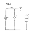
- Fig. 6 is a block diagram illustrating the configuration of a related-art circuit used in measuring current and voltage to evaluate battery characteristics.
- a load 2 and an ammeter 3 are connected in series to a battery 1 as a measurement target and a voltmeter 4 is connected in parallel to the battery 1.
- the ammeter 3 measures a rising or falling value of output current of the battery 1 varying depending on the turning-on/off of the load 2
- the voltmeter 4 measures a rising or falling value of output voltage of the battery 1 varying depending on the turning-on/off of the load 2.
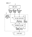
- Fig. 7 is a block diagram illustrating the configuration of a related-art battery characteristic evaluator for evaluating battery characteristics of a battery based on the measurement result of Fig. 6 .
- Current value data IM measured by the ammeter 3, voltage value data VM measured by the voltmeter 4, and standard equivalent circuit model data EM of the battery 1 prepared in advance are input to an input unit 5.
- a circuit constant optimizing unit 6 includes a voltage calculator 6a and a determination unit 6b, optimizes a circuit constant of an equivalent circuit model of the battery 1 as an identification value FV based on the current value data IM measured by the ammeter 3, the voltage value data VM measured by the voltmeter 4, and the equivalent circuit model data EM of the battery 1 which are input from the input unit 5, and outputs the optimized circuit constant of the equivalent circuit model to an output unit 7.
- the current value data IM measured by the ammeter 3, the equivalent circuit model data EM of the battery 1, and a candidate of the circuit constant CC from the determination unit 6b are input to the voltage calculator 6a, and a calculated voltage value VC is calculated and provided to the determination unit 6b.
- the voltage value data VM measured by the voltmeter 4 and the calculated voltage value VC calculated by the voltage calculator 6a are input to the determination unit 6b.
- the measured voltage value data VM and the calculated voltage value VC are compared with each other and it is determined whether the circuit constant is the optimal value.
- a new circuit constant CC is generated from the comparison result and is input to the voltage calculator 6a, and the voltage is calculated again. These processes are repeatedly performed until it is determined that the circuit constant is the optimal value.
- the identification value FV optimized as the circuit constant of the equivalent circuit model in this way is provided to the output unit 7.
- the output unit 7 generates a characteristic curve of the battery 1 based on the identification value FV of the circuit constant of the equivalent circuit model optimized by the circuit constant optimizing unit 6 and displays the generated characteristic curve on a display unit (not shown).
- Fig. 8 is a diagram illustrating an equivalent circuit representing the characteristics of the battery 1.
- a DC source E a resistor R1, a parallel circuit of a resistor R2 and a capacitor C1
- a parallel circuit of a resistor R3 and a capacitor C2 are connected in series.
- circuit constant optimizing unit 6 calculates resistance values R1, R2, and R3 of the resistors and capacitance values C1 and C2 of the capacitors so as to reduce a difference between the calculated voltage value and the measured voltage value.
- JP-A-2003-4780 discloses the configuration of method and apparatus for measuring internal impedance of a battery.
- JP-A-2005-100969 discloses removing an influence of a response voltage due to polarization at the time of measuring internal impedance of a battery.
- Warburg impedance In a low-frequency region of impedance of the battery 1, Warburg impedance is exhibited due to the influence of diffusion.
- the Warburg impedance may be calculated as impedance in a frequency domain as shown in Fig. 9 , but it is difficult to transform the impedance in the frequency domain into impedance in a time domain. Accordingly, the Warburg impedance in the related-art equivalent circuit is expressed by a resistor, a capacitor, and an inductor.
- Exemplary embodiments of the present invention address the above disadvantages and other disadvantages not described above.
- the present invention is not required to overcome the disadvantages described above, and thus, an exemplary embodiment of the present invention may not overcome any disadvantages.
- a battery characteristic evaluator configured to identify a circuit constant of an equivalent circuit model based on a current-voltage characteristic of a battery.
- the evaluator includes: a current waveform divider configured to divide a certain current waveform into a plurality of step functions with a plurality of infinitesimal time intervals and output the step functions; and a circuit constant optimizing unit configured to calculate the optimized circuit constant of the equivalent circuit model, based on the step functions, a measured voltage value, and equivalent circuit model data.
- FIG. 1 is a block diagram illustrating an embodiment of the invention, where elements common to those shown in Fig. 7 are referenced by like reference numerals and signs.
- a current waveform divider 8 divides a measured value IM of a certain current waveform into plural step functions having different time axes as shown in Fig. 2.
- Fig. 2 shows an example where a rising region of a current waveform is divided into n step functions I 1 to I n and a falling region is divided into m step functions I n+1 to I n+m The step functions I 1 to I n+m are input to a circuit constant optimizing unit 6.
- a step response calculator 6c and a voltage adder 6d adding the response calculation results V 1 to V n+m of the step response calculator 6c are provided instead of the voltage calculator 6a of Fig. 7 .
- Equivalent circuit model data EM a candidate of a circuit constant CC from a determination unit 6b, and the step functions I 1 to I n+m corresponding to the current from the current waveform divider 8 are input to the step response calculator 6c. Accordingly, the step response calculator 6c calculates step response voltages V 1 to V n+m , for the current given as the step functions I 1 to I n+m and inputs the step response voltages V 1 to V n+m as the calculation results to an input terminal of the voltage adder 6d.
- the voltage adder 6d adds the step response voltages V 1 to V n+m as the calculation results of the step response calculator 6c to obtain a calculated voltage value VC. Then, the calculated voltage value VC is provided to the determination unit 6b.
- Voltage value data VM measured by a voltmeter 4 and the calculated voltage value VC calculated by the voltage adder 6d are input to the determination unit 6b.
- the measured voltage value VM and the calculated voltage value VC are compared to determine whether the circuit constant is the optimal value as the comparison result.
- a new circuit constant CC is generated from the comparison result and is input to the step response calculator 6c so as to calculate a voltage again. These processes are repeatedly performed until it is determined that the circuit constant is the optimal value.
- An identification value FV optimized as the circuit constant of the equivalent circuit model in this way is provided to an output unit 7.
- the output unit 7 generates a characteristic curve of the battery 1 based on the identification value FV of the circuit constant of the equivalent circuit model optimized by the circuit constant optimizing unit 6 and displays the generated characteristic curve on a display unit (not shown).
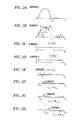
- Figs. 2A to 2H The details shown in Figs. 2A to 2H will be described below.
- the rising region p of the certain waveform current I(t) shown in Fig. 2A is divided into n step functions as shown in Figs. 2B to 2H , and the falling region n is divided into m step functions.
- This can be expressed by a mathematical expression as follows.
- u(t) represents a unit step function with amplitude 1.
- V i (t i ) When step current flows in impedance Z, transient voltage response signals V i (t i ) are obtained as follows by the Laplace-transforming Expression (4).
- V i t i L
- V i t i L
- V t V 1 t 1 + V 2 t 2 + V 3 t 3 + ... + V n t n - V n + 1 ⁇ t n + 1 - V n + 2 ⁇ t n + 2 ... - V n + m ⁇ t n + m
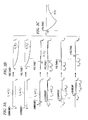
- FIGs. 3A to 3C are diagrams illustrating the recombination based on the superposition of the step responses in the circuit shown in Fig. 1 , excluding the power source.
- Fig. 3A shows the step functions of a certain current waveform
- Fig. 3B shows the step responses
- Fig. 3C shows the superposition of the step responses.
- Fig. 4 is a diagram illustrating an equivalent circuit including the Warburg impedance representing the battery characteristic.
- a DC source E a resistor R1, a parallel circuit of a resistor R2 and a capacitor C1 and a parallel circuit of a series circuit of a resistor R3 and a Warburg impedance W1 representing the diffusion of materials and a capacitor C2 are connected in series.
- the Warburg impedance can be included in the equivalent circuit and the identification precision of the battery increases, thereby making the current-voltage characteristic closer to reality. Realistic values can be obtained for the circuit constants other than the Warburg impedance.
- Fig. 5 the conventional method is applied to the voltage in a circuit block in which an RLC circuit is connected in series and the method according to the invention is applied to the voltage in a Warburg impedance block.
- Vw in the time domain of the Warburg impedance block W1 can be calculated as follows and thus the calculation is simplified.
- Vw ⁇ ⁇ 2 ⁇ t ⁇ Ip / ⁇ 3 / 2 , where ⁇ represents a constant of diffusion and ⁇ represents a gamma function.
- the total voltage of the equivalent circuit shown in Fig. 5 is calculated as the sum of the voltage in the Warburg impedance W1 block and the voltage in the RLC circuit block.
- the voltages calculated by the methods are compared with the measured voltage value for evaluation.
- the method according to the invention can be applied when the input current has a rectangular waveform.
- the current is changed and identified with the measured response voltage, but the voltage may be changed and identified with the measured current value.
- a battery characteristic evaluator which can identify a circuit constant with high precision in an equivalent circuit model of a battery in consideration of the Warburg impedance so as to evaluate a battery characteristic with high precision, and can be suitably used to efficiently analyze various parameters of a battery.
Landscapes
- Physics & Mathematics (AREA)
- General Physics & Mathematics (AREA)
- Secondary Cells (AREA)
- Tests Of Electric Status Of Batteries (AREA)
- Measurement Of Resistance Or Impedance (AREA)
Abstract
Description
- The present invention relates to a battery characteristic evaluator..
-
Fig. 6 is a block diagram illustrating the configuration of a related-art circuit used in measuring current and voltage to evaluate battery characteristics. Aload 2 and an ammeter 3 are connected in series to abattery 1 as a measurement target and avoltmeter 4 is connected in parallel to thebattery 1. - The ammeter 3 measures a rising or falling value of output current of the
battery 1 varying depending on the turning-on/off of theload 2, and thevoltmeter 4 measures a rising or falling value of output voltage of thebattery 1 varying depending on the turning-on/off of theload 2. Such a specific measurement procedure is described inJP-A-2003-4780 -
Fig. 7 is a block diagram illustrating the configuration of a related-art battery characteristic evaluator for evaluating battery characteristics of a battery based on the measurement result ofFig. 6 . Current value data IM measured by the ammeter 3, voltage value data VM measured by thevoltmeter 4, and standard equivalent circuit model data EM of thebattery 1 prepared in advance are input to aninput unit 5. - A circuit
constant optimizing unit 6 includes avoltage calculator 6a and adetermination unit 6b, optimizes a circuit constant of an equivalent circuit model of thebattery 1 as an identification value FV based on the current value data IM measured by the ammeter 3, the voltage value data VM measured by thevoltmeter 4, and the equivalent circuit model data EM of thebattery 1 which are input from theinput unit 5, and outputs the optimized circuit constant of the equivalent circuit model to anoutput unit 7. - In the circuit
constant optimizing unit 6, the current value data IM measured by the ammeter 3, the equivalent circuit model data EM of thebattery 1, and a candidate of the circuit constant CC from thedetermination unit 6b are input to thevoltage calculator 6a, and a calculated voltage value VC is calculated and provided to thedetermination unit 6b. - The voltage value data VM measured by the
voltmeter 4 and the calculated voltage value VC calculated by thevoltage calculator 6a are input to thedetermination unit 6b. The measured voltage value data VM and the calculated voltage value VC are compared with each other and it is determined whether the circuit constant is the optimal value. When it is determined that the circuit constant is not the optimal value, a new circuit constant CC is generated from the comparison result and is input to thevoltage calculator 6a, and the voltage is calculated again. These processes are repeatedly performed until it is determined that the circuit constant is the optimal value. The identification value FV optimized as the circuit constant of the equivalent circuit model in this way is provided to theoutput unit 7. - The
output unit 7 generates a characteristic curve of thebattery 1 based on the identification value FV of the circuit constant of the equivalent circuit model optimized by the circuitconstant optimizing unit 6 and displays the generated characteristic curve on a display unit (not shown). -
Fig. 8 is a diagram illustrating an equivalent circuit representing the characteristics of thebattery 1. In the equivalent circuit shown inFig. 8 , a DC source E, a resistor R1, a parallel circuit of a resistor R2 and a capacitor C1, and a parallel circuit of a resistor R3 and a capacitor C2 are connected in series. - When circuit data shown in
Fig. 8 is input as the equivalent circuit model data EM, the circuitconstant optimizing unit 6 calculates resistance values R1, R2, and R3 of the resistors and capacitance values C1 and C2 of the capacitors so as to reduce a difference between the calculated voltage value and the measured voltage value. -
JP-A-2003-4780
JP-A-2005-100969 - In a low-frequency region of impedance of the
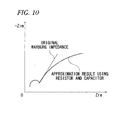
battery 1, Warburg impedance is exhibited due to the influence of diffusion. The Warburg impedance may be calculated as impedance in a frequency domain as shown inFig. 9 , but it is difficult to transform the impedance in the frequency domain into impedance in a time domain. Accordingly, the Warburg impedance in the related-art equivalent circuit is expressed by a resistor, a capacitor, and an inductor. - However, a voltage drop curve based on the Warburg impedance could not be reproduced by the combination of a resistor and a capacitor. Nevertheless, when the identification thereof is performed using a DC source, a resistor, and a capacitor, the resistance value of the resistor or the capacitance value of the capacitor becomes a large value that does not correspond to reality as shown in
Fig. 10 , thereby making the circuit constant identification meaningless. - Exemplary embodiments of the present invention address the above disadvantages and other disadvantages not described above. However, the present invention is not required to overcome the disadvantages described above, and thus, an exemplary embodiment of the present invention may not overcome any disadvantages.
- Accordingly, it is an illustrative aspect of the present invention to provide a battery characteristic evaluator which can improve precision of a circuit constant identification value in an equivalent circuit model of a battery in view of Warburg impedance.
- According to one or more illustrative aspects of the present invention, there is provided a battery characteristic evaluator configured to identify a circuit constant of an equivalent circuit model based on a current-voltage characteristic of a battery. The evaluator includes: a current waveform divider configured to divide a certain current waveform into a plurality of step functions with a plurality of infinitesimal time intervals and output the step functions; and a circuit constant optimizing unit configured to calculate the optimized circuit constant of the equivalent circuit model, based on the step functions, a measured voltage value, and equivalent circuit model data.
- Other aspects and advantages of the present invention will be apparent from the following description, the drawings and the claims.
-
-
Fig. 1 is a block diagram illustrating an example of the invention; -
Figs. 2A to 2H are diagrams illustrating an operation of dividing a certain waveform current into step functions; -
Figs. 3A to 3C are diagrams illustrating a recombination by the superposition of step responses in the circuit shown inFigs. 2A to 2H , excluding a power source; -
Fig. 4 is a diagram illustrating an equivalent circuit including Warburg impedance, which represents a battery characteristic; -
Fig. 5 is a diagram illustrating an equivalent circuit in which the Warburg impedance W1 is singly connected in series; -
Fig. 6 is a block diagram illustrating the configuration of a related-art circuit used in measuring current and voltage to evaluate the battery characteristic; -
Fig. 7 is a block diagram illustrating a related-art battery characteristic evaluator for evaluating the battery characteristic based on the measurement result ofFig. 6 ; -
Fig. 8 is a diagram illustrating an equivalent circuit representing the battery characteristic; -
Fig. 9 is a diagram illustrating the Warburg impedance; and -
Fig. 10 is a diagram illustrating an example where the Warburg impedance is approximated by a resistor and a capacitor. - Hereinafter, exemplary embodiments of the present invention will be described with reference to the accompanying drawings.
Fig. 1 is a block diagram illustrating an embodiment of the invention, where elements common to those shown inFig. 7 are referenced by like reference numerals and signs. - In
Fig. 1 , acurrent waveform divider 8 divides a measured value IM of a certain current waveform into plural step functions having different time axes as shown inFig. 2. Fig. 2 shows an example where a rising region of a current waveform is divided into n step functions I1 to In and a falling region is divided into m step functions In+1 to In+m The step functions I1 to In+m are input to a circuitconstant optimizing unit 6. - In the circuit
constant optimizing unit 6, astep response calculator 6c and avoltage adder 6d adding the response calculation results V1 to Vn+m of thestep response calculator 6c are provided instead of thevoltage calculator 6a ofFig. 7 . - Equivalent circuit model data EM, a candidate of a circuit constant CC from a
determination unit 6b, and the step functions I1 to In+m corresponding to the current from thecurrent waveform divider 8 are input to thestep response calculator 6c. Accordingly, thestep response calculator 6c calculates step response voltages V1 to Vn+m, for the current given as the step functions I1 to In+m and inputs the step response voltages V1 to Vn+m as the calculation results to an input terminal of thevoltage adder 6d. - The
voltage adder 6d adds the step response voltages V1 to Vn+m as the calculation results of thestep response calculator 6c to obtain a calculated voltage value VC. Then, the calculated voltage value VC is provided to thedetermination unit 6b. - Voltage value data VM measured by a
voltmeter 4 and the calculated voltage value VC calculated by thevoltage adder 6d are input to thedetermination unit 6b. The measured voltage value VM and the calculated voltage value VC are compared to determine whether the circuit constant is the optimal value as the comparison result. When it is determined that the circuit constant is not the optimal value, a new circuit constant CC is generated from the comparison result and is input to thestep response calculator 6c so as to calculate a voltage again. These processes are repeatedly performed until it is determined that the circuit constant is the optimal value. An identification value FV optimized as the circuit constant of the equivalent circuit model in this way is provided to anoutput unit 7. - The
output unit 7 generates a characteristic curve of thebattery 1 based on the identification value FV of the circuit constant of the equivalent circuit model optimized by the circuitconstant optimizing unit 6 and displays the generated characteristic curve on a display unit (not shown). - The details shown in
Figs. 2A to 2H will be described below. The rising region p of the certain waveform current I(t) shown inFig. 2A is divided into n step functions as shown inFigs. 2B to 2H , and the falling region n is divided into m step functions. This can be expressed by a mathematical expression as follows. Here, u(t) represents a unit step function withamplitude 1. -

where u(t) is set so that u(ti) = 0 (if ti < 0) and 1 (if ti ≥ 0) at time ti (where i = 1 to n + m). - In
Expression 1, Ii (ti) (where I = 1 to n) can be expressed as follows by the Laplace transform.
- Similarly, Ii(ti) (where i = n + 1 to n + m) can be also expressed as follows by the Laplace transform.

- Since these current signals flow in impedance Z(s) and are thus converted into voltages, the voltages Vi(s) (where i = 1 to n + m) based on the currents are expressed as follows.

- When step current flows in impedance Z, transient voltage response signals Vi(ti) are obtained as follows by the Laplace-transforming Expression (4).

- Therefore, by recombining the step responses divided into (n + m) steps, a transient voltage response waveform V(t) when a certain current waveform flows in the impedance Z can be expressed by Expression (6).

- Accordingly, even when a certain current waveform is input, it is possible to calculate a voltage response of the battery.
Figs. 3A to 3C are diagrams illustrating the recombination based on the superposition of the step responses in the circuit shown inFig. 1 , excluding the power source. InFigs. 3A to 3C, Fig. 3A shows the step functions of a certain current waveform,Fig. 3B shows the step responses, andFig. 3C shows the superposition of the step responses. -
Fig. 4 is a diagram illustrating an equivalent circuit including the Warburg impedance representing the battery characteristic. InFig. 4 , a DC source E, a resistor R1, a parallel circuit of a resistor R2 and a capacitor C1 and a parallel circuit of a series circuit of a resistor R3 and a Warburg impedance W1 representing the diffusion of materials and a capacitor C2 are connected in series. - According to this configuration, the Warburg impedance can be included in the equivalent circuit and the identification precision of the battery increases, thereby making the current-voltage characteristic closer to reality. Realistic values can be obtained for the circuit constants other than the Warburg impedance.
- Although the equivalent circuit model in which the Warburg impedance is connected in parallel has been described in the above-mentioned embodiment, an equivalent circuit in which the Warburg impedance W1 is singly connected in series as shown in
Fig. 5 can be implemented by easy calculation. - In
Fig. 5 , the conventional method is applied to the voltage in a circuit block in which an RLC circuit is connected in series and the method according to the invention is applied to the voltage in a Warburg impedance block. - In this case, the voltage Vw in the time domain of the Warburg impedance block W1 can be calculated as follows and thus the calculation is simplified.

where δ represents a constant of diffusion and Γ represents a gamma function. - The total voltage of the equivalent circuit shown in
Fig. 5 is calculated as the sum of the voltage in the Warburg impedance W1 block and the voltage in the RLC circuit block. The voltages calculated by the methods are compared with the measured voltage value for evaluation. - The method according to the invention can be applied when the input current has a rectangular waveform.
- In the above-mentioned embodiment, the current is changed and identified with the measured response voltage, but the voltage may be changed and identified with the measured current value.
- According to the above-mentioned invention, it is possible to provide a battery characteristic evaluator which can identify a circuit constant with high precision in an equivalent circuit model of a battery in consideration of the Warburg impedance so as to evaluate a battery characteristic with high precision, and can be suitably used to efficiently analyze various parameters of a battery.
Claims (8)
- A battery characteristic evaluator configured to identify a circuit constant of an equivalent circuit model based on a current-voltage characteristic of a battery, the evaluator comprising:a current waveform divider configured to divide a certain current waveform into a plurality of step functions with a plurality of infinitesimal time intervals and output the step functions; anda circuit constant optimizing unit configured to calculate the optimized circuit constant of the equivalent circuit model, based on the step functions, a measured voltage value, and equivalent circuit model data.
- The evaluator of Claim 1,
wherein the circuit constant optimizing unit comprises:a step response calculator configured to calculate a plurality of step response voltages each corresponding to one of the plurality of step functions, based on the plurality of step functions and the equivalent circuit model data;a voltage adder configured to add each of the step response voltages to output a calculated voltage value; anda determination unit configured to determine whether the circuit constant is the optimal value, by comparing the calculated voltage value with the measured voltage value,wherein when the determination unit determines that the circuit constant is not the optimal value, the determination unit generates a new circuit constant based on the comparison result, and provides the new circuit constant to the step response calculator. - A battery characteristic evaluator configured to identify a circuit constant of an equivalent circuit model based on a current-voltage characteristic of a battery, the evaluator comprising:a voltage waveform divider configured to divide a certain voltage waveform into a plurality of step functions with a plurality of infinitesimal time intervals and output the step functions; anda circuit constant optimizing unit configured to calculate the optimized circuit constant of the equivalent circuit model, based on the step functions, a measured current value, and equivalent circuit model data.
- The evaluator of Claim 3,
wherein the circuit constant optimizing unit comprises:a step response calculator configured to calculate a plurality of step response currents each corresponding to one of the plurality of step functions, based on the plurality of step functions and the equivalent circuit model data;a current adder configured to add each of the step response currents to output a calculated current value; anda determination unit configured to determine whether the circuit constant is the optimal value, by comparing the measured current value with the calculated current value,wherein when the determination unit determines that the circuit constant is not the optimal value, the determination unit generates a new circuit constant based on the comparison result, and provides the generated circuit constant to the step response calculator. - The evaluator of Claim 1, wherein the equivalent circuit model comprises Warburg impedance.
- The evaluator of Claim 2, wherein the equivalent circuit model comprises Warburg impedance.
- The evaluator of Claim 3, wherein the equivalent circuit model comprises Warburg impedance.
- The evaluator of Claim 4, wherein the equivalent circuit model comprises Warburg impedance.
Applications Claiming Priority (1)
| Application Number | Priority Date | Filing Date | Title |
|---|---|---|---|
| JP2010002803A JP4835757B2 (en) | 2010-01-08 | 2010-01-08 | Battery characteristic evaluation device |
Publications (3)
| Publication Number | Publication Date |
|---|---|
| EP2345905A2 true EP2345905A2 (en) | 2011-07-20 |
| EP2345905A3 EP2345905A3 (en) | 2015-07-01 |
| EP2345905B1 EP2345905B1 (en) | 2016-08-03 |
Family
ID=43825247
Family Applications (1)
| Application Number | Title | Priority Date | Filing Date |
|---|---|---|---|
| EP10197399.8A Active EP2345905B1 (en) | 2010-01-08 | 2010-12-30 | Battery characteristic evaluator |
Country Status (5)
| Country | Link |
|---|---|
| US (1) | US20110173585A1 (en) |
| EP (1) | EP2345905B1 (en) |
| JP (1) | JP4835757B2 (en) |
| KR (1) | KR101144684B1 (en) |
| CN (1) | CN102129041B (en) |
Families Citing this family (16)
| Publication number | Priority date | Publication date | Assignee | Title |
|---|---|---|---|---|
| JP5403437B2 (en) | 2011-07-29 | 2014-01-29 | 横河電機株式会社 | Battery monitoring device |
| JP6035028B2 (en) * | 2012-02-03 | 2016-11-30 | 横河電機株式会社 | Battery characteristics deriving device |
| JP5847685B2 (en) * | 2012-10-24 | 2016-01-27 | カルソニックカンセイ株式会社 | Parameter identification apparatus and identification method for continuous time system |
| JP5946436B2 (en) * | 2013-10-21 | 2016-07-06 | カルソニックカンセイ株式会社 | Battery parameter estimation apparatus and parameter estimation method |
| JP6183283B2 (en) * | 2014-04-23 | 2017-08-23 | 株式会社デンソー | Parameter estimation device for equivalent circuit of secondary battery for vehicle |
| US9312722B2 (en) | 2014-05-09 | 2016-04-12 | Ford Global Technologies, Llc | System and method for battery power management |
| US20160001672A1 (en) * | 2014-07-01 | 2016-01-07 | Ford Global Technologies, Llc | Equivalent circuit based battery current limit estimations |
| CN104678225B (en) * | 2015-03-13 | 2017-08-25 | 上海理工大学 | Automobile batteries emulator |
| CN106371018B (en) * | 2015-07-21 | 2019-05-24 | 上汽通用汽车有限公司 | Power cell of vehicle method for diagnosing faults and equipment based on battery terminal voltage estimation |
| JP6528598B2 (en) * | 2015-08-20 | 2019-06-12 | 株式会社デンソー | Diffusion resistance identification device for secondary battery |
| KR101989692B1 (en) * | 2017-09-26 | 2019-06-14 | 주식회사 포스코아이씨티 | Method and System for Diagnosing Battery Aging |
| JP6893164B2 (en) * | 2017-11-13 | 2021-06-23 | プライムアースEvエナジー株式会社 | Battery status measuring device and battery status measuring method |
| CN110361657B (en) * | 2019-08-09 | 2021-09-14 | 厦门海泰新能技术有限公司 | Method for estimating state of charge of battery |
| CN110443216B (en) * | 2019-08-13 | 2021-08-24 | 树根互联股份有限公司 | Production mode identification method and device of production equipment |
| DE102019132768A1 (en) * | 2019-12-03 | 2021-06-10 | Audi Ag | Calibration device for calibrating an electrical equivalent circuit |
| JP6842212B1 (en) * | 2019-12-26 | 2021-03-17 | 東洋システム株式会社 | Battery performance evaluation method and battery performance evaluation device |
Citations (2)
| Publication number | Priority date | Publication date | Assignee | Title |
|---|---|---|---|---|
| JP2003004780A (en) | 2001-04-20 | 2003-01-08 | Nf Corp | Method and apparatus for estimation of impedance parameter |
| JP2005100969A (en) | 2003-08-22 | 2005-04-14 | Furukawa Electric Co Ltd:The | Secondary battery internal impedance measuring method, secondary battery internal impedance measuring apparatus and power supply system |
Family Cites Families (14)
| Publication number | Priority date | Publication date | Assignee | Title |
|---|---|---|---|---|
| CN1027192C (en) * | 1989-10-25 | 1994-12-28 | 菲利浦光灯制造公司 | Device for determing charge condition of battery |
| US6990422B2 (en) * | 1996-03-27 | 2006-01-24 | World Energy Labs (2), Inc. | Method of analyzing the time-varying electrical response of a stimulated target substance |
| KR19980065966A (en) * | 1997-01-17 | 1998-10-15 | 김광호 | Battery capacity indicator |
| US6167349A (en) * | 1998-04-02 | 2000-12-26 | Btech, Inc. | Battery parameter measurement |
| JP3587073B2 (en) * | 1998-05-27 | 2004-11-10 | トヨタ自動車株式会社 | Control device for air-fuel ratio sensor |
| KR100262465B1 (en) * | 1998-06-25 | 2000-08-01 | 박찬구 | Method and apparatus for determining battery capacity by measuring and analysing battery's voltage response signal generated by current pulse |
| US6262577B1 (en) * | 1998-09-18 | 2001-07-17 | Matsushita Electric Industrial Co., Ltd. | Method of measuring quantities indicating state of electrochemical device and apparatus for the same |
| KR100395516B1 (en) * | 1998-11-19 | 2003-12-18 | 금호석유화학 주식회사 | Method and apparatus for digitizing characteristic factor of power storage device using nonlinear equivalent circuit model |
| US6737831B2 (en) * | 1999-09-01 | 2004-05-18 | Keith S. Champlin | Method and apparatus using a circuit model to evaluate cell/battery parameters |
| DE10021161A1 (en) * | 2000-04-29 | 2001-10-31 | Vb Autobatterie Gmbh | Method for determining the state of charge and the load capacity of an electric accumulator |
| JP4657017B2 (en) * | 2005-06-14 | 2011-03-23 | 日置電機株式会社 | AC amplifier and impedance measuring device |
| JP2007093596A (en) * | 2005-08-31 | 2007-04-12 | Chinontec Kk | Relaxation modulus measurement method, relaxation modulus measurement program, recording medium storing the program, and mold manufacturing method |
| EP1892536B1 (en) * | 2006-08-22 | 2012-04-11 | Delphi Technologies, Inc. | Battery monitoring system |
| US7768233B2 (en) * | 2007-10-04 | 2010-08-03 | Gm Global Technology Operations, Inc. | Dynamically adaptive method for determining the state of charge of a battery |
-
2010
- 2010-01-08 JP JP2010002803A patent/JP4835757B2/en active Active
- 2010-12-30 EP EP10197399.8A patent/EP2345905B1/en active Active
-
2011
- 2011-01-06 US US12/985,417 patent/US20110173585A1/en not_active Abandoned
- 2011-01-07 KR KR1020110001749A patent/KR101144684B1/en active Active
- 2011-01-10 CN CN201110020695.6A patent/CN102129041B/en active Active
Patent Citations (2)
| Publication number | Priority date | Publication date | Assignee | Title |
|---|---|---|---|---|
| JP2003004780A (en) | 2001-04-20 | 2003-01-08 | Nf Corp | Method and apparatus for estimation of impedance parameter |
| JP2005100969A (en) | 2003-08-22 | 2005-04-14 | Furukawa Electric Co Ltd:The | Secondary battery internal impedance measuring method, secondary battery internal impedance measuring apparatus and power supply system |
Also Published As
| Publication number | Publication date |
|---|---|
| JP4835757B2 (en) | 2011-12-14 |
| JP2011141228A (en) | 2011-07-21 |
| KR101144684B1 (en) | 2012-05-24 |
| EP2345905A3 (en) | 2015-07-01 |
| CN102129041B (en) | 2014-04-16 |
| CN102129041A (en) | 2011-07-20 |
| US20110173585A1 (en) | 2011-07-14 |
| KR20110081784A (en) | 2011-07-14 |
| EP2345905B1 (en) | 2016-08-03 |
Similar Documents
| Publication | Publication Date | Title |
|---|---|---|
| EP2345905B1 (en) | Battery characteristic evaluator | |
| US20240248146A1 (en) | Multispectral impedance determination under dynamic load conditions | |
| EP3317683B1 (en) | Energy storage cell impedance measuring apparatus, methods and related systems | |
| CN104698273B (en) | Harmonic contributions division method and system | |
| US20140312922A1 (en) | Device and method for determining capacitance | |
| Waag et al. | Application-specific parameterization of reduced order equivalent circuit battery models for improved accuracy at dynamic load | |
| KR20050061386A (en) | Apparatus and method for testing state of charge in battery using neural network | |
| KR20130119871A (en) | Cell direct-current resistance evaluation system | |
| EP3896776A1 (en) | Simulated battery construction method and simulated battery construction device | |
| CN117368623B (en) | A towable energy storage inverter aging inspection method, system and medium | |
| US20090088995A1 (en) | Method for determining the linear electrical response of a transformer, generator or electrical motor | |
| JP2011123033A (en) | Device for evaluating battery characteristics | |
| JP2011122917A (en) | Device for evaluating battery characteristics | |
| Li et al. | Accurate loop gain prediction for DC-DC converter due to the impact of source/input filter | |
| US20190025357A1 (en) | Frequency regulation method and apparatus | |
| EP1684081B1 (en) | Method and device for characterizing the linear properties of an electrical component | |
| US20170336241A1 (en) | Circuit for Simulating a Capacitance Fuel Probe | |
| KR102512544B1 (en) | Battery equivalent circuit generation method and apparatus | |
| JP2011122918A (en) | Device for evaluating battery characteristics | |
| JP2011085445A (en) | Battery characteristics simulator | |
| CN117390862A (en) | Performance evaluation methods, devices and equipment for AC/DC conversion equipment | |
| JP2009064617A (en) | Fuel cell equivalent circuit model and fuel cell characteristics evaluation method | |
| JP2009099389A (en) | Fuel cell simulator and fuel cell simulation method | |
| US20050088183A1 (en) | Methods for determining inductance and resistance of an inductor | |
| Vilsen et al. | An auto-regressive model for battery voltage prediction |
Legal Events
| Date | Code | Title | Description |
|---|---|---|---|
| PUAI | Public reference made under article 153(3) epc to a published international application that has entered the european phase |
Free format text: ORIGINAL CODE: 0009012 |
|
| AK | Designated contracting states |
Kind code of ref document: A2 Designated state(s): AL AT BE BG CH CY CZ DE DK EE ES FI FR GB GR HR HU IE IS IT LI LT LU LV MC MK MT NL NO PL PT RO RS SE SI SK SM TR |
|
| AX | Request for extension of the european patent |
Extension state: BA ME |
|
| PUAL | Search report despatched |
Free format text: ORIGINAL CODE: 0009013 |
|
| AK | Designated contracting states |
Kind code of ref document: A3 Designated state(s): AL AT BE BG CH CY CZ DE DK EE ES FI FR GB GR HR HU IE IS IT LI LT LU LV MC MK MT NL NO PL PT RO RS SE SI SK SM TR |
|
| AX | Request for extension of the european patent |
Extension state: BA ME |
|
| RIC1 | Information provided on ipc code assigned before grant |
Ipc: G01R 31/36 20060101AFI20150528BHEP |
|
| 17P | Request for examination filed |
Effective date: 20151209 |
|
| RBV | Designated contracting states (corrected) |
Designated state(s): AL AT BE BG CH CY CZ DE DK EE ES FI FR GB GR HR HU IE IS IT LI LT LU LV MC MK MT NL NO PL PT RO RS SE SI SK SM TR |
|
| GRAP | Despatch of communication of intention to grant a patent |
Free format text: ORIGINAL CODE: EPIDOSNIGR1 |
|
| INTG | Intention to grant announced |
Effective date: 20160408 |
|
| GRAS | Grant fee paid |
Free format text: ORIGINAL CODE: EPIDOSNIGR3 |
|
| GRAA | (expected) grant |
Free format text: ORIGINAL CODE: 0009210 |
|
| AK | Designated contracting states |
Kind code of ref document: B1 Designated state(s): AL AT BE BG CH CY CZ DE DK EE ES FI FR GB GR HR HU IE IS IT LI LT LU LV MC MK MT NL NO PL PT RO RS SE SI SK SM TR |
|
| REG | Reference to a national code |
Ref country code: GB Ref legal event code: FG4D |
|
| REG | Reference to a national code |
Ref country code: CH Ref legal event code: EP Ref country code: AT Ref legal event code: REF Ref document number: 817683 Country of ref document: AT Kind code of ref document: T Effective date: 20160815 |
|
| REG | Reference to a national code |
Ref country code: IE Ref legal event code: FG4D |
|
| REG | Reference to a national code |
Ref country code: DE Ref legal event code: R096 Ref document number: 602010035160 Country of ref document: DE |
|
| REG | Reference to a national code |
Ref country code: NL Ref legal event code: MP Effective date: 20160803 |
|
| REG | Reference to a national code |
Ref country code: LT Ref legal event code: MG4D |
|
| REG | Reference to a national code |
Ref country code: AT Ref legal event code: MK05 Ref document number: 817683 Country of ref document: AT Kind code of ref document: T Effective date: 20160803 |
|
| PG25 | Lapsed in a contracting state [announced via postgrant information from national office to epo] |
Ref country code: IS Free format text: LAPSE BECAUSE OF FAILURE TO SUBMIT A TRANSLATION OF THE DESCRIPTION OR TO PAY THE FEE WITHIN THE PRESCRIBED TIME-LIMIT Effective date: 20161203 Ref country code: FI Free format text: LAPSE BECAUSE OF FAILURE TO SUBMIT A TRANSLATION OF THE DESCRIPTION OR TO PAY THE FEE WITHIN THE PRESCRIBED TIME-LIMIT Effective date: 20160803 Ref country code: HR Free format text: LAPSE BECAUSE OF FAILURE TO SUBMIT A TRANSLATION OF THE DESCRIPTION OR TO PAY THE FEE WITHIN THE PRESCRIBED TIME-LIMIT Effective date: 20160803 Ref country code: NL Free format text: LAPSE BECAUSE OF FAILURE TO SUBMIT A TRANSLATION OF THE DESCRIPTION OR TO PAY THE FEE WITHIN THE PRESCRIBED TIME-LIMIT Effective date: 20160803 Ref country code: RS Free format text: LAPSE BECAUSE OF FAILURE TO SUBMIT A TRANSLATION OF THE DESCRIPTION OR TO PAY THE FEE WITHIN THE PRESCRIBED TIME-LIMIT Effective date: 20160803 Ref country code: LT Free format text: LAPSE BECAUSE OF FAILURE TO SUBMIT A TRANSLATION OF THE DESCRIPTION OR TO PAY THE FEE WITHIN THE PRESCRIBED TIME-LIMIT Effective date: 20160803 Ref country code: IT Free format text: LAPSE BECAUSE OF FAILURE TO SUBMIT A TRANSLATION OF THE DESCRIPTION OR TO PAY THE FEE WITHIN THE PRESCRIBED TIME-LIMIT Effective date: 20160803 Ref country code: NO Free format text: LAPSE BECAUSE OF FAILURE TO SUBMIT A TRANSLATION OF THE DESCRIPTION OR TO PAY THE FEE WITHIN THE PRESCRIBED TIME-LIMIT Effective date: 20161103 |
|
| PG25 | Lapsed in a contracting state [announced via postgrant information from national office to epo] |
Ref country code: SE Free format text: LAPSE BECAUSE OF FAILURE TO SUBMIT A TRANSLATION OF THE DESCRIPTION OR TO PAY THE FEE WITHIN THE PRESCRIBED TIME-LIMIT Effective date: 20160803 Ref country code: LV Free format text: LAPSE BECAUSE OF FAILURE TO SUBMIT A TRANSLATION OF THE DESCRIPTION OR TO PAY THE FEE WITHIN THE PRESCRIBED TIME-LIMIT Effective date: 20160803 Ref country code: GR Free format text: LAPSE BECAUSE OF FAILURE TO SUBMIT A TRANSLATION OF THE DESCRIPTION OR TO PAY THE FEE WITHIN THE PRESCRIBED TIME-LIMIT Effective date: 20161104 Ref country code: PL Free format text: LAPSE BECAUSE OF FAILURE TO SUBMIT A TRANSLATION OF THE DESCRIPTION OR TO PAY THE FEE WITHIN THE PRESCRIBED TIME-LIMIT Effective date: 20160803 Ref country code: ES Free format text: LAPSE BECAUSE OF FAILURE TO SUBMIT A TRANSLATION OF THE DESCRIPTION OR TO PAY THE FEE WITHIN THE PRESCRIBED TIME-LIMIT Effective date: 20160803 Ref country code: PT Free format text: LAPSE BECAUSE OF FAILURE TO SUBMIT A TRANSLATION OF THE DESCRIPTION OR TO PAY THE FEE WITHIN THE PRESCRIBED TIME-LIMIT Effective date: 20161205 Ref country code: AT Free format text: LAPSE BECAUSE OF FAILURE TO SUBMIT A TRANSLATION OF THE DESCRIPTION OR TO PAY THE FEE WITHIN THE PRESCRIBED TIME-LIMIT Effective date: 20160803 |
|
| PG25 | Lapsed in a contracting state [announced via postgrant information from national office to epo] |
Ref country code: RO Free format text: LAPSE BECAUSE OF FAILURE TO SUBMIT A TRANSLATION OF THE DESCRIPTION OR TO PAY THE FEE WITHIN THE PRESCRIBED TIME-LIMIT Effective date: 20160803 Ref country code: EE Free format text: LAPSE BECAUSE OF FAILURE TO SUBMIT A TRANSLATION OF THE DESCRIPTION OR TO PAY THE FEE WITHIN THE PRESCRIBED TIME-LIMIT Effective date: 20160803 |
|
| REG | Reference to a national code |
Ref country code: DE Ref legal event code: R097 Ref document number: 602010035160 Country of ref document: DE |
|
| PG25 | Lapsed in a contracting state [announced via postgrant information from national office to epo] |
Ref country code: CZ Free format text: LAPSE BECAUSE OF FAILURE TO SUBMIT A TRANSLATION OF THE DESCRIPTION OR TO PAY THE FEE WITHIN THE PRESCRIBED TIME-LIMIT Effective date: 20160803 Ref country code: BG Free format text: LAPSE BECAUSE OF FAILURE TO SUBMIT A TRANSLATION OF THE DESCRIPTION OR TO PAY THE FEE WITHIN THE PRESCRIBED TIME-LIMIT Effective date: 20161103 Ref country code: DK Free format text: LAPSE BECAUSE OF FAILURE TO SUBMIT A TRANSLATION OF THE DESCRIPTION OR TO PAY THE FEE WITHIN THE PRESCRIBED TIME-LIMIT Effective date: 20160803 Ref country code: SK Free format text: LAPSE BECAUSE OF FAILURE TO SUBMIT A TRANSLATION OF THE DESCRIPTION OR TO PAY THE FEE WITHIN THE PRESCRIBED TIME-LIMIT Effective date: 20160803 Ref country code: BE Free format text: LAPSE BECAUSE OF FAILURE TO SUBMIT A TRANSLATION OF THE DESCRIPTION OR TO PAY THE FEE WITHIN THE PRESCRIBED TIME-LIMIT Effective date: 20160803 Ref country code: SM Free format text: LAPSE BECAUSE OF FAILURE TO SUBMIT A TRANSLATION OF THE DESCRIPTION OR TO PAY THE FEE WITHIN THE PRESCRIBED TIME-LIMIT Effective date: 20160803 |
|
| PLBE | No opposition filed within time limit |
Free format text: ORIGINAL CODE: 0009261 |
|
| STAA | Information on the status of an ep patent application or granted ep patent |
Free format text: STATUS: NO OPPOSITION FILED WITHIN TIME LIMIT |
|
| 26N | No opposition filed |
Effective date: 20170504 |
|
| REG | Reference to a national code |
Ref country code: CH Ref legal event code: PL |
|
| GBPC | Gb: european patent ceased through non-payment of renewal fee |
Effective date: 20161230 |
|
| PG25 | Lapsed in a contracting state [announced via postgrant information from national office to epo] |
Ref country code: SI Free format text: LAPSE BECAUSE OF FAILURE TO SUBMIT A TRANSLATION OF THE DESCRIPTION OR TO PAY THE FEE WITHIN THE PRESCRIBED TIME-LIMIT Effective date: 20160803 |
|
| PG25 | Lapsed in a contracting state [announced via postgrant information from national office to epo] |
Ref country code: MC Free format text: LAPSE BECAUSE OF FAILURE TO SUBMIT A TRANSLATION OF THE DESCRIPTION OR TO PAY THE FEE WITHIN THE PRESCRIBED TIME-LIMIT Effective date: 20160803 |
|
| REG | Reference to a national code |
Ref country code: FR Ref legal event code: ST Effective date: 20170831 |
|
| REG | Reference to a national code |
Ref country code: IE Ref legal event code: MM4A |
|
| PG25 | Lapsed in a contracting state [announced via postgrant information from national office to epo] |
Ref country code: LI Free format text: LAPSE BECAUSE OF NON-PAYMENT OF DUE FEES Effective date: 20161231 Ref country code: CH Free format text: LAPSE BECAUSE OF NON-PAYMENT OF DUE FEES Effective date: 20161231 Ref country code: LU Free format text: LAPSE BECAUSE OF NON-PAYMENT OF DUE FEES Effective date: 20161230 Ref country code: FR Free format text: LAPSE BECAUSE OF NON-PAYMENT OF DUE FEES Effective date: 20170102 |
|
| PG25 | Lapsed in a contracting state [announced via postgrant information from national office to epo] |
Ref country code: IE Free format text: LAPSE BECAUSE OF NON-PAYMENT OF DUE FEES Effective date: 20161230 Ref country code: GB Free format text: LAPSE BECAUSE OF NON-PAYMENT OF DUE FEES Effective date: 20161230 |
|
| PG25 | Lapsed in a contracting state [announced via postgrant information from national office to epo] |
Ref country code: CY Free format text: LAPSE BECAUSE OF FAILURE TO SUBMIT A TRANSLATION OF THE DESCRIPTION OR TO PAY THE FEE WITHIN THE PRESCRIBED TIME-LIMIT Effective date: 20160803 Ref country code: HU Free format text: LAPSE BECAUSE OF FAILURE TO SUBMIT A TRANSLATION OF THE DESCRIPTION OR TO PAY THE FEE WITHIN THE PRESCRIBED TIME-LIMIT; INVALID AB INITIO Effective date: 20101230 |
|
| PG25 | Lapsed in a contracting state [announced via postgrant information from national office to epo] |
Ref country code: MK Free format text: LAPSE BECAUSE OF FAILURE TO SUBMIT A TRANSLATION OF THE DESCRIPTION OR TO PAY THE FEE WITHIN THE PRESCRIBED TIME-LIMIT Effective date: 20160803 Ref country code: TR Free format text: LAPSE BECAUSE OF FAILURE TO SUBMIT A TRANSLATION OF THE DESCRIPTION OR TO PAY THE FEE WITHIN THE PRESCRIBED TIME-LIMIT Effective date: 20160803 |
|
| PG25 | Lapsed in a contracting state [announced via postgrant information from national office to epo] |
Ref country code: MT Free format text: LAPSE BECAUSE OF NON-PAYMENT OF DUE FEES Effective date: 20161230 |
|
| PG25 | Lapsed in a contracting state [announced via postgrant information from national office to epo] |
Ref country code: AL Free format text: LAPSE BECAUSE OF FAILURE TO SUBMIT A TRANSLATION OF THE DESCRIPTION OR TO PAY THE FEE WITHIN THE PRESCRIBED TIME-LIMIT Effective date: 20160803 |
|
| P01 | Opt-out of the competence of the unified patent court (upc) registered |
Effective date: 20230603 |
|
| PGFP | Annual fee paid to national office [announced via postgrant information from national office to epo] |
Ref country code: DE Payment date: 20251126 Year of fee payment: 16 |