EP2345902A1 - Inspection vehicle for inspecting an air gap between the rotor and the stator of a generator - Google Patents
Inspection vehicle for inspecting an air gap between the rotor and the stator of a generator Download PDFInfo
- Publication number
- EP2345902A1 EP2345902A1 EP11150283A EP11150283A EP2345902A1 EP 2345902 A1 EP2345902 A1 EP 2345902A1 EP 11150283 A EP11150283 A EP 11150283A EP 11150283 A EP11150283 A EP 11150283A EP 2345902 A1 EP2345902 A1 EP 2345902A1
- Authority
- EP
- European Patent Office
- Prior art keywords
- inspection vehicle
- drive elements
- permanent magnets
- case
- housing
- Prior art date
- Legal status (The legal status is an assumption and is not a legal conclusion. Google has not performed a legal analysis and makes no representation as to the accuracy of the status listed.)
- Granted
Links
Images



Classifications
-
- H—ELECTRICITY
- H02—GENERATION; CONVERSION OR DISTRIBUTION OF ELECTRIC POWER
- H02K—DYNAMO-ELECTRIC MACHINES
- H02K15/00—Processes or apparatus specially adapted for manufacturing, assembling, maintaining or repairing of dynamo-electric machines
-
- B—PERFORMING OPERATIONS; TRANSPORTING
- B62—LAND VEHICLES FOR TRAVELLING OTHERWISE THAN ON RAILS
- B62D—MOTOR VEHICLES; TRAILERS
- B62D57/00—Vehicles characterised by having other propulsion or other ground- engaging means than wheels or endless track, alone or in addition to wheels or endless track
- B62D57/02—Vehicles characterised by having other propulsion or other ground- engaging means than wheels or endless track, alone or in addition to wheels or endless track with ground-engaging propulsion means, e.g. walking members
- B62D57/024—Vehicles characterised by having other propulsion or other ground- engaging means than wheels or endless track, alone or in addition to wheels or endless track with ground-engaging propulsion means, e.g. walking members specially adapted for moving on inclined or vertical surfaces
-
- G—PHYSICS
- G01—MEASURING; TESTING
- G01R—MEASURING ELECTRIC VARIABLES; MEASURING MAGNETIC VARIABLES
- G01R31/00—Arrangements for testing electric properties; Arrangements for locating electric faults; Arrangements for electrical testing characterised by what is being tested not provided for elsewhere
- G01R31/34—Testing dynamo-electric machines
Definitions
- the present invention relates to the field of technology of electric heavy-duty generators. It refers to an inspection vehicle for inspecting an air gap between the rotor and the stator of such a generator according to the preamble of claim 1.
- an inspection device is introduced into the air gap, that is to say into the gap between rotor and stator, with which the outer surface of the rotor can be inspected visually and electromagnetically, as well as the inner surface of the stator. Furthermore, the mechanical integrity of the windings and the associated winding wedges can be checked.
- the air gap customarily has a width of between 10 and 30 mm, but with the rotor installed, the width of the access between the end ring of the generator and the stator may even be only about 9 mm.
- the first can be referred to as a "cable car" device.
- a sensor carrier 15 is introduced into the air gap 14 of the generator 10 between a central rotor 11 and a stator 12 which concentrically encloses the rotor 11, and is fastened on a wire 18 which is guided in the axial direction through the air gap 14 and by means of reels 16 and 17, which are arranged at the ends, can be moved back and forth in the axial direction (see the double arrow).
- a comparable device is disclosed in printed publication EP 1 233 278 A2 . In the case of this device, it is disadvantageous that with simultaneous removal of large parts of the casing the device has to be inconveniently fastened on the generator.
- a second family, the construction of which is schematically reproduced in Fig. 2 instead of the continuous wire uses a thin, inherently stiff band 19, on the free end of which the sensor carrier 15 is fastened.
- the band 19 can be displaced in the axial direction by means of a roll-up mechanism 20.
- the roll-up mechanism can be moved around the rotor 11 in the circumferential direction in order to reach all regions of the rotor top surface or of the stator inner surface with the sensor carrier 15.
- the main disadvantage lies in the fastening on the generator and the disassembly cost which is associated therewith.
- the third family of inspection devices which is schematically shown in Fig. 3 , includes a robot 21 as the central component, which can be moved autonomously in the air gap 14 by it being rolled over, and consequently moved along, the surfaces of the rotor 11 and of the stator 12 via tracked drives 22, 23 which are arranged on the upper side and lower side.
- the tracked drives 22, 23 are pressed onto the respective surface by means of a spreader mechanism in the process in order to achieve sufficient friction for the drive and accurate positioning.
- Such a solution is known for example from printed publication US 2008/0087112 A1 .
- Such a robot on the one hand is very costly in construction and operation, and on the other hand is not compact enough to be introduced from the outside into the air gap of different generators and to be moved in all regions there.
- the inspection vehicle according to the invention is characterized in that the drive elements are formed as elongated, flexionally elastic, torsionally rigid, magnetic rolls. With these rolls, the vehicle is held simultaneously on the magnetizable rotor or stator and is moved progressively by rotation of the rolls.
- the flexibility of the rolls ensures that the rolls can be adapted to the curved surface in the air gap and so can optimize not only the magnetic adhesion but also the friction between roll and surface which is required for the drive.
- the elongated shape of the elements ensures that a sufficiently large magnetizable area of the rotor or stator is always covered.
- One development of the inspection vehicle according to the invention is characterized in that the drive elements have the form of a flexible tube section in each case.
- Another development of the inspection vehicle according to the invention is characterized in that a multiplicity of permanent magnets are arranged inside the drive elements one behind the other in the longitudinal direction.
- the drive elements comprise flexionally elastic, torsionally rigid shafts, on which a multiplicity of permanent magnets are arranged in each case one behind the other in the longitudinal direction in a rotation-resisting manner.
- the permanent magnets are of cylindrical or hollow-cylindrical design, wherein the cylinder axis is oriented parallel to the longitudinal axis of the drive elements in each case.
- Another development of the inspection vehicle according to the invention is characterized in that the permanent magnets are magnetized parallel to the cylinder axis in each case.
- a further development of the inspection vehicle according to the invention is characterized in that the permanent magnets of a drive element are arranged inside a flexible tube.
- Another development of the inspection vehicle according to the invention is characterized in that the flexible tube is a rubber tube.
- Another development of the inspection vehicle according to the invention is characterized in that the flexible tube has an outside diameter which is constant over the longitudinal axis.
- Another development of the inspection vehicle according to the invention is characterized in that the permanent magnets of a shaft are covered with a protective sheath.
- the inspection vehicle has a housing or a carrier structure with sensors which are required for the inspection, and in that at least one drive element is arranged in each case on opposite sides of the housing or of the carrier structure.
- Another development of the inspection vehicle according to the invention is characterized in that a plurality of drive elements are arranged in each case on one side of the housing or of the carrier structure.
- Another development of the inspection vehicle according to the invention is characterized in that the drive elements with their longitudinal axes are arranged parallel to each other, and in that the drive elements are connected to the housing or to the carrier structure in a manner in which they are rotatable around their longitudinal axes.
- Another development of the inspection vehicle according to the invention is characterized in that the drive elements are individually driven, and in that for each of the drive elements provision is made in the housing or in the carrier structure for a motor which sets the associated drive element in rotation around its longitudinal axis.
- Another development of the inspection vehicle according to the invention is characterized in that a control unit for controlling the motors is accommodated in the housing or in the carrier structure.
- Another development of the inspection vehicle according to the invention is characterized in that the rotational direction of the drive elements is variable in each case.
- Another development of the inspection vehicle according to the invention is characterized in that the flexionally elastic, torsionally rigid, magnetic rolls of the drive elements are mounted in correspondingly flexionally elastic frames which prevent distortion of the rolls around an axis which is perpendicular to the roll surface of the rolls.
- a generator 10 has a rotor 11, which from the technical point of view is the ferromagnetic core of an electromagnet which rotates around the machine axis (13 in Fig. 4 ) in order to convert mechanical energy into electric energy.
- windings 36 (normally consisting of copper) of electrically good conductivity are installed in the rotor 11. These windings 36 are secured in corresponding slots by means of so-called "wedges".
- the wedges are produced from non-ferromagnetic material such as aluminum or stainless steel, so that the rotor surface in the region of the wedges is not suitable for magnetic attraction.
- the rotor 11 rotates in the stator 12.
- the gap which remains free between rotor 11 and stator 12, that is to say the air gap 14, has a width in the region of 20 - 30 mm.
- an inspection vehicle 24 which is provided with various instruments and sensors (for example cameras, measured value transducers, control electronics, communication electronics; see Fig. 5 ), is now introduced into the air gap 14.
- the instruments and sensors (37 in Fig. 5 ) or the associated control unit and electronics are accommodated in a housing 25 (or in a carrier structure 38 according to Fig. 8 ).
- the inspection vehicle 24 can be autonomously progressively moved in the air gap 14 by means of two or more drive elements 26, 27 which are formed as flexible magnetic rolls.
- a flexible tube 31 especially in the form of a rubber tube, is filled with a large number of individual cylindrical permanent magnets 32, 33 which are magnetized parallel to the longitudinal axis of the tube 31 and for example can be arranged in the tube alternating with the magnetizing direction (see Fig. 7 ), but do not necessarily have to be so.
- the length of the tube section is selected so that the tube section extends over a plurality of windings and therefore in any case covers a magnetizable region of the surface.
- Other solutions for the flexible tube are also conceivable, however (see Fig. 9 and Fig. 10 ).
- the tube-like drive elements 26, 27 of the solution which is shown are equipped at one end in each case with a connecting element 34 which via a drive axis 35 is connected to a motor 29 or 30 which is accommodated in the housing 25 ( Figs. 5 and 6 ).
- the inspection vehicle 24 can be controlled by means of different directions of rotation and speeds of the drive elements 26, 27. This takes place for example by means of a control unit 28 which controls the motors 29 and 30.
- the flexible magnetic drive elements 26 and 27 adapt themselves to the curved outer surface of the rotor 11 (or to the curved inner surface of the stator 12) in order to hold the inspection vehicle 24 firmly on the surface and at the same time to create sufficient friction for the drive movement.
- the housing 25 of the inspection vehicle 24, if its dimensions are small in comparison to the circumference, can be flat in construction. It is also conceivable, however, to adapt the housing 25 to the curvature of rotor 11 and stator 12, as is shown in Fig. 4 . Also, it is possible for the housing 25 itself to be of a flexible design so that it can be adapted to the curvature.
- an inspection vehicle 24' in which a plurality of parallel drive elements 26a - c or 27a - c are arranged on each side.
- the synchronous rotation of the drive elements of each side can be achieved either via internal gears or via corresponding controlling of individual drive motors.
- an open carrier structure 38 for the fastening of the drive, control unit and sensors instead of the housing which is described above, because such a carrier structure 38 can be simply constructed in a flexionally elastic manner, for example by using thin metal strips.
- the embodiments of the drive elements 26, 39 and 42 from Figures 7 , 9 and 10 are basically equally flexible in all directions which are perpendicular to the rotational axis. On the other hand, in essence a bending flexibility which is perpendicular to the surface which is to be inspected is desired.
- a construction according to Fig. 11 or Fig. 12 can be used.
- a shaft 40 which is equipped with hollow-cylindrical permanent magnets 41 Fig.
- a frame 45 which, like the shaft 40, is similarly flexible in the direction which is perpendicular to the surface which is to be inspected, but prevents bending being carried out around an axis which is perpendicular to the surface which is to be inspected.
- the combination consisting of shaft 40 and frame 45 therefore results in a drive element 44 with properties which are similar to a flat rubber mat.
- a plurality of shafts 40 with corresponding permanent magnets 41 can also be arranged horizontally parallel in a common frame 47 in order to form a corresponding drive element 46. Furthermore, it can be advantageous to attach or to connect the drive elements 44 or 46 with their frames 45 or 47 directly to a carrier structure 38 according to Fig. 8 .
Landscapes
- Engineering & Computer Science (AREA)
- Manufacturing & Machinery (AREA)
- Power Engineering (AREA)
- Chemical & Material Sciences (AREA)
- Combustion & Propulsion (AREA)
- Transportation (AREA)
- Mechanical Engineering (AREA)
- Electric Propulsion And Braking For Vehicles (AREA)
- Permanent Magnet Type Synchronous Machine (AREA)
- Connection Of Motors, Electrical Generators, Mechanical Devices, And The Like (AREA)
Abstract
Description
- The present invention relates to the field of technology of electric heavy-duty generators. It refers to an inspection vehicle for inspecting an air gap between the rotor and the stator of such a generator according to the preamble of
claim 1. - The inspection of air gaps in large generators in the assembled state has the advantage that the rotor does not have to be withdrawn from the generator, but only minimal operations need to be undertaken for opening the casing. This leads to great time savings and shortens the downtimes of the generator considerably.
- For the inspection, an inspection device is introduced into the air gap, that is to say into the gap between rotor and stator, with which the outer surface of the rotor can be inspected visually and electromagnetically, as well as the inner surface of the stator. Furthermore, the mechanical integrity of the windings and the associated winding wedges can be checked. The air gap customarily has a width of between 10 and 30 mm, but with the rotor installed, the width of the access between the end ring of the generator and the stator may even be only about 9 mm.
- In the past, a large number of devices for in-situ inspection in the air gap of generators have already been proposed. All known devices and methods have some disadvantages. Often, they are not universal enough to be easily adapted to the different generator geometries, and the devices are frequently too large to be introduced through a standard inspection opening in the generator. Their size leads to a partial opening of the casing, which costs valuable time and leads to an outage of the machine.
- In the prior art, three main families of in-situ inspection devices for the air gaps of generators can be distinguished: the first can be referred to as a "cable car" device. Such a device is schematically shown in
Fig. 1 . Asensor carrier 15 is introduced into theair gap 14 of thegenerator 10 between acentral rotor 11 and astator 12 which concentrically encloses therotor 11, and is fastened on awire 18 which is guided in the axial direction through theair gap 14 and by means ofreels publication EP 1 233 278 A2 . In the case of this device, it is disadvantageous that with simultaneous removal of large parts of the casing the device has to be inconveniently fastened on the generator. - A second family, the construction of which is schematically reproduced in
Fig. 2 , instead of the continuous wire uses a thin, inherentlystiff band 19, on the free end of which thesensor carrier 15 is fastened. Theband 19 can be displaced in the axial direction by means of a roll-up mechanism 20. As in the case of the solution ofFig. 1 , in this case the roll-up mechanism can be moved around therotor 11 in the circumferential direction in order to reach all regions of the rotor top surface or of the stator inner surface with thesensor carrier 15. Also in this case, the main disadvantage lies in the fastening on the generator and the disassembly cost which is associated therewith. - The third family of inspection devices, which is schematically shown in
Fig. 3 , includes arobot 21 as the central component, which can be moved autonomously in theair gap 14 by it being rolled over, and consequently moved along, the surfaces of therotor 11 and of thestator 12 via trackeddrives drives US 2008/0087112 A1 . Such a robot on the one hand is very costly in construction and operation, and on the other hand is not compact enough to be introduced from the outside into the air gap of different generators and to be moved in all regions there. - It is therefore an object of the invention to create an inspection vehicle which avoids the disadvantages of known solutions and which is especially characterized by simplicity in construction, robustness, great maneuverability and high flexibility in use.
- The object is achieved by means of the entirety of the features of
claim 1. The inspection vehicle according to the invention is characterized in that the drive elements are formed as elongated, flexionally elastic, torsionally rigid, magnetic rolls. With these rolls, the vehicle is held simultaneously on the magnetizable rotor or stator and is moved progressively by rotation of the rolls. The flexibility of the rolls ensures that the rolls can be adapted to the curved surface in the air gap and so can optimize not only the magnetic adhesion but also the friction between roll and surface which is required for the drive. The elongated shape of the elements ensures that a sufficiently large magnetizable area of the rotor or stator is always covered. - One development of the inspection vehicle according to the invention is characterized in that the drive elements have the form of a flexible tube section in each case.
- Another development of the inspection vehicle according to the invention is characterized in that a multiplicity of permanent magnets are arranged inside the drive elements one behind the other in the longitudinal direction.
- Another development of the inspection vehicle according to the invention is characterized in that the drive elements comprise flexionally elastic, torsionally rigid shafts, on which a multiplicity of permanent magnets are arranged in each case one behind the other in the longitudinal direction in a rotation-resisting manner.
- Another development of the inspection vehicle according to the invention is characterized in that the permanent magnets are of cylindrical or hollow-cylindrical design, wherein the cylinder axis is oriented parallel to the longitudinal axis of the drive elements in each case.
- Another development of the inspection vehicle according to the invention is characterized in that the permanent magnets are magnetized parallel to the cylinder axis in each case.
- A further development of the inspection vehicle according to the invention is characterized in that the permanent magnets of a drive element are arranged inside a flexible tube.
- Another development of the inspection vehicle according to the invention is characterized in that the flexible tube is a rubber tube.
- Another development of the inspection vehicle according to the invention is characterized in that the flexible tube has an outside diameter which is constant over the longitudinal axis.
- Another development of the inspection vehicle according to the invention is characterized in that the permanent magnets of a shaft are covered with a protective sheath.
- Another development of the inspection vehicle according to the invention is characterized in that the inspection vehicle has a housing or a carrier structure with sensors which are required for the inspection, and in that at least one drive element is arranged in each case on opposite sides of the housing or of the carrier structure.
- Another development of the inspection vehicle according to the invention is characterized in that a plurality of drive elements are arranged in each case on one side of the housing or of the carrier structure.
- Another development of the inspection vehicle according to the invention is characterized in that the drive elements with their longitudinal axes are arranged parallel to each other, and in that the drive elements are connected to the housing or to the carrier structure in a manner in which they are rotatable around their longitudinal axes.
- Another development of the inspection vehicle according to the invention is characterized in that the drive elements are individually driven, and in that for each of the drive elements provision is made in the housing or in the carrier structure for a motor which sets the associated drive element in rotation around its longitudinal axis.
- Another development of the inspection vehicle according to the invention is characterized in that a control unit for controlling the motors is accommodated in the housing or in the carrier structure.
- Another development of the inspection vehicle according to the invention is characterized in that the rotational direction of the drive elements is variable in each case.
- Another development of the inspection vehicle according to the invention is characterized in that the flexionally elastic, torsionally rigid, magnetic rolls of the drive elements are mounted in correspondingly flexionally elastic frames which prevent distortion of the rolls around an axis which is perpendicular to the roll surface of the rolls.
- The invention shall subsequently be explained in more detail based on exemplary embodiments in conjunction with the drawing. In the drawing
-
Fig. 1 shows in a greatly simplified view a method for inspecting the air gap of a generator according to the prior art; -
Fig. 2 shows in a greatly simplified view another method for inspecting the air gap of a generator according to the prior art; -
Fig. 3 shows in a greatly simplified view a vehicle for inspecting the air gap of a generator according to the prior art; -
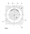
Fig. 4 shows, as seen in the axial direction, the use of an inspection vehicle according to an exemplary embodiment of the invention; -
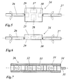
Fig. 5 shows an inspection vehicle of the type shown inFig. 4 , in plan view from above; -
Fig. 6 shows the same inspection vehicle in side view; -
Fig. 7 shows the exemplary inner construction of a drive element of the inspection vehicle fromFig. 5 ; -
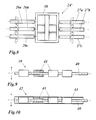
Fig. 8 shows in a view which is comparable toFig. 5 an inspection vehicle according to another exemplary embodiment of the invention with an open carrier structure for drive, control unit and sensors, and also a plurality of parallel drive elements on each side; -
Fig. 9 shows in a view which is comparable toFig. 7 another drive element, in which hollow-cylindrical or ring-like permanent magnets are arranged in a rotation-resisting manner on a flexible, torsionally rigid shaft; -
Fig. 10 shows a drive element corresponding toFig. 9 , in which the permanent magnets are protected by means of a thin protective sheath which is drawn over them; -
Fig. 11 shows in plan view from above (Fig. 11a ) and in a side view (Fig. 11b ) a drive element which is based onFig. 9 , in which the shafts with the permanent magnets are mounted in a flexible, simultaneously stabilizing frame; -
Fig. 12 shows in plan view from above a drive element which is comparable toFig. 11 , in which a plurality of parallel shafts are mounted in a flexible, simultaneously stabilizing frame; and -
Fig. 13 shows in a perspective view the use of an inspection vehicle according toFig. 5 in the air gap. - As shown in
Fig. 13 , agenerator 10 has arotor 11, which from the technical point of view is the ferromagnetic core of an electromagnet which rotates around the machine axis (13 inFig. 4 ) in order to convert mechanical energy into electric energy. In order to form the magnet, windings 36 (normally consisting of copper) of electrically good conductivity are installed in therotor 11. Thesewindings 36 are secured in corresponding slots by means of so-called "wedges". The wedges are produced from non-ferromagnetic material such as aluminum or stainless steel, so that the rotor surface in the region of the wedges is not suitable for magnetic attraction. Therotor 11 rotates in thestator 12. The gap which remains free betweenrotor 11 andstator 12, that is to say theair gap 14, has a width in the region of 20 - 30 mm. - According to the invention, an
inspection vehicle 24, which is provided with various instruments and sensors (for example cameras, measured value transducers, control electronics, communication electronics; seeFig. 5 ), is now introduced into theair gap 14. The instruments and sensors (37 inFig. 5 ) or the associated control unit and electronics are accommodated in a housing 25 (or in acarrier structure 38 according toFig. 8 ). Theinspection vehicle 24 can be autonomously progressively moved in theair gap 14 by means of two ormore drive elements - A possible realization of
such drive elements Fig. 7 andFig. 13 . In this example, aflexible tube 31, especially in the form of a rubber tube, is filled with a large number of individual cylindricalpermanent magnets tube 31 and for example can be arranged in the tube alternating with the magnetizing direction (seeFig. 7 ), but do not necessarily have to be so. The length of the tube section is selected so that the tube section extends over a plurality of windings and therefore in any case covers a magnetizable region of the surface. Other solutions for the flexible tube are also conceivable, however (seeFig. 9 and Fig. 10 ). It is also conceivable to interconnect the permanent magnets themselves in a flexible but rotation-resisting manner in order to act as flexible magnetic rolls. Also, it is conceivable to produce thedrive elements - The tube-
like drive elements element 34 which via adrive axis 35 is connected to amotor Figs. 5 and 6 ). Theinspection vehicle 24 can be controlled by means of different directions of rotation and speeds of thedrive elements control unit 28 which controls themotors - As is to be seen from
Fig. 13 andFig. 4 , the flexiblemagnetic drive elements inspection vehicle 24 firmly on the surface and at the same time to create sufficient friction for the drive movement. Thehousing 25 of theinspection vehicle 24, if its dimensions are small in comparison to the circumference, can be flat in construction. It is also conceivable, however, to adapt thehousing 25 to the curvature ofrotor 11 andstator 12, as is shown inFig. 4 . Also, it is possible for thehousing 25 itself to be of a flexible design so that it can be adapted to the curvature. - In order to increase the adherence to the surfaces which are to be inspected and at the same time to provide the friction which is necessary for the progressive movement, it can be advantageous to use an inspection vehicle 24' according to
Fig. 8 , in which a plurality ofparallel drive elements 26a - c or 27a - c are arranged on each side. The synchronous rotation of the drive elements of each side can be achieved either via internal gears or via corresponding controlling of individual drive motors. Likewise, it can be advantageous to use anopen carrier structure 38 for the fastening of the drive, control unit and sensors instead of the housing which is described above, because such acarrier structure 38 can be simply constructed in a flexionally elastic manner, for example by using thin metal strips. - Furthermore, instead of the rubber tubes which are filled with the permanent magnets, it is conceivable to provide flexionally elastic, torsionally
rigid shafts 40 for the drive elements according toFig. 9 or Fig. 10 , on which hollow-cylindricalpermanent magnets 41 are arranged one behind the other in the longitudinal direction in a rotation-resisting manner. The embodiment of thedrive elements 39 according toFig. 9 , in which thepermanent magnets 41 have direct contact with the surface which is to be inspected, is characterized by especially high holding forces, but is limited with regard to friction and is exposed to contaminants during operation. In order to achieve an improvement in this case, with thedrive elements 42 according toFig. 10 the arrangement ofshaft 40 andpermanent magnets 41 can be covered with a thinprotective sheath 43 which weakens the holding forces comparatively little, but offers protection for the arrangement against contamination and, with a suitable selection of material, significantly improves friction. - The embodiments of the
drive elements Figures 7 ,9 and 10 are basically equally flexible in all directions which are perpendicular to the rotational axis. On the other hand, in essence a bending flexibility which is perpendicular to the surface which is to be inspected is desired. In order to achieve such a directed flexibility with the drive elements, a construction according toFig. 11 or Fig. 12 can be used. In one case, ashaft 40 which is equipped with hollow-cylindrical permanent magnets 41 (Fig. 11 ) is mounted in aframe 45 which, like theshaft 40, is similarly flexible in the direction which is perpendicular to the surface which is to be inspected, but prevents bending being carried out around an axis which is perpendicular to the surface which is to be inspected. The combination consisting ofshaft 40 andframe 45 therefore results in adrive element 44 with properties which are similar to a flat rubber mat. - According to
Fig. 12 , in this way a plurality ofshafts 40 with correspondingpermanent magnets 41 can also be arranged horizontally parallel in acommon frame 47 in order to form acorresponding drive element 46. Furthermore, it can be advantageous to attach or to connect thedrive elements frames carrier structure 38 according toFig. 8 . -
- 10
- Generator
- 11
- Rotor
- 12
- Stator
- 13
- Machine axis
- 14
- Air gap
- 15
- Sensor carrier
- 16, 17
- Reel
- 18
- Wire
- 19
- Band
- 20
- Roll-up mechanism
- 21
- Robot
- 22, 23
- Tracked drive
- 24, 24'
- Inspection vehicle
- 25
- Housing
- 26, 27
- Drive element
- 26a - c
- Drive element
- 27a - c
- Drive element
- 28
- Control unit
- 29, 30
- Motor
- 31
- Flexible tube (for example rubber tube)
- 32, 33
- Permanent magnet (cylindrical)
- 34
- Connecting element
- 35
- Drive axis
- 36
- Winding
- 37
- Sensor
- 38
- Carrier structure
- 39, 42
- Drive element
- 40
- Shaft (flexible)
- 41
- Permanent magnet (hollow-cylindrical)
- 43
- Protective sheath
- 44, 46
- Drive element
- 45, 47
- Frame
Claims (17)
- An inspection vehicle (24, 24') for inspecting an air gap (14) between the rotor (11) and the stator (12) of a generator (10), which inspection vehicle (24, 24') has drive elements (26, 27; 26a - c, 27a - c; 39, 42, 44, 46) for the independent progressive movement in the air gap (14), characterized in that the drive elements (26, 27; 26a - c, 27a - c; 39, 42, 44, 46) comprise elongated, flexionally elastic, torsionally rigid, magnetic rolls.
- The inspection vehicle as claimed in claim 1, characterized in that the drive elements (26, 27; 26a - c, 27a - c) have the form of a flexible tube section in each case.
- The inspection vehicle as claimed in claim 1 or 2, characterized in that a multiplicity of permanent magnets (32, 33) are arranged inside the drive elements (26, 27; 26a - c, 27a - c) one behind the other in the longitudinal direction.
- The inspection vehicle as claimed in claim 1, characterized in that the drive elements (39, 42, 44, 46) comprise flexionally elastic, torsionally rigid shafts (40), on which a multiplicity of permanent magnets (41) are arranged in each case one behind the other in the longitudinal direction in a rotation-resisting manner.
- The inspection vehicle as claimed in claim 3 or 4, characterized in that the permanent magnets (32, 33; 41) are of cylindrical or hollow-cylindrical design, wherein the cylinder axis is oriented in each case parallel to the longitudinal axis of the drive elements (26, 27; 26a - c, 27a - c; 39, 42, 44, 46).
- The inspection vehicle as claimed in claim 5, characterized in that the permanent magnets (32, 33; 41) are magnetized parallel to the cylinder axis in each case.
- The inspection vehicle as claimed in claim 2 or 3, characterized in that the permanent magnets (32, 33) of a drive element (26, 27) are arranged inside a flexible tube (31).
- The inspection vehicle as claimed in claim 7, characterized in that the flexible tube (31) is a rubber tube.
- The inspection vehicle as claimed in claim 7 or 8, characterized in that the flexible tube (31) has an outside diameter which is constant over the longitudinal axis.
- The inspection vehicle as claimed in claim 4, characterized in that the permanent magnets (41) of a shaft (40) are covered with a protective sheath (43).
- The inspection vehicle as claimed in one of claims 1 - 10, characterized in that the inspection vehicle (24, 24') has a housing (25) or a carrier structure (38) with sensors (37) which are required for the inspection, and in that at least one drive element (26, 27; 26a - c, 27a - c; 39, 42, 44, 46) is arranged in each case on opposite sides of the housing (25) or of the carrier structure (38).
- The inspection vehicle as claimed in claim 11, characterized in that a plurality of drive elements (26a - c, 27a - c) are arranged in each case on one side of the housing (25) or of the carrier structure (38).
- The inspection vehicle as claimed in claim 11 or 12, characterized in that the drive elements (26, 27; 26a - c, 27a - c) with their longitudinal axes are arranged parallel to each other, and in that the drive elements (26, 27; 26a - c, 27a - c) are connected to the housing (25) or to the carrier structure (38) in a manner in which they are rotatable around their longitudinal axes.
- The inspection vehicle as claimed in claim 11, characterized in that the drive elements (26, 27; 26a - c, 27a - c; 39, 42, 44, 46) are individually driven, and in that for each of the drive elements (26, 27; 26a - c, 27a - c; 39, 42, 44, 46) provision is made in the housing (25) or on the carrier structure (38) for a motor (29, 30) which sets the associated drive element (26, 27; 26a - c, 27a - c; 39, 42, 44, 46) in rotation around its longitudinal axis.
- The inspection vehicle as claimed in claim 14, characterized in that a control unit (28) for controlling the motors (29, 30) is accommodated in the housing (25) or in the carrier structure (38).
- The inspection vehicle as claimed in claim 14 or 15, characterized in that the rotational direction of the drive elements (26, 27; 26a - c, 27a - c; 39, 42, 44, 46) is variable in each case.
- The inspection vehicle as claimed in claim 1, characterized in that the flexionally elastic, torsionally rigid, magnetic rolls of the drive elements (44, 46) are mounted in correspondingly flexionally elastic frames (45, 47) which prevent distortion of the rolls around an axis which is perpendicular to the roll surface of the rolls.
Applications Claiming Priority (2)
| Application Number | Priority Date | Filing Date | Title |
|---|---|---|---|
| US29619910P | 2010-01-19 | 2010-01-19 | |
| CH01312/10A CH703662A1 (en) | 2010-08-16 | 2010-08-16 | Inspection vehicle for the inspection of air gap between rotor and stator a generator. |
Publications (2)
| Publication Number | Publication Date |
|---|---|
| EP2345902A1 true EP2345902A1 (en) | 2011-07-20 |
| EP2345902B1 EP2345902B1 (en) | 2013-01-02 |
Family
ID=43333219
Family Applications (1)
| Application Number | Title | Priority Date | Filing Date |
|---|---|---|---|
| EP11150283A Not-in-force EP2345902B1 (en) | 2010-01-19 | 2011-01-06 | Inspection vehicle for inspecting an air gap between the rotor and the stator of a generator |
Country Status (8)
| Country | Link |
|---|---|
| US (1) | US8789432B2 (en) |
| EP (1) | EP2345902B1 (en) |
| BR (1) | BRPI1100580A8 (en) |
| CA (1) | CA2728263C (en) |
| CH (1) | CH703662A1 (en) |
| ES (1) | ES2402237T3 (en) |
| MX (1) | MX2011000496A (en) |
| PT (1) | PT2345902E (en) |
Cited By (11)
| Publication number | Priority date | Publication date | Assignee | Title |
|---|---|---|---|---|
| WO2015095543A1 (en) * | 2013-12-18 | 2015-06-25 | Abb Technology Ag | Modular confined space crawler for use in machinery |
| EP3067258A1 (en) * | 2015-03-09 | 2016-09-14 | General Electric Technology GmbH | Magnetic roller |
| WO2019018071A1 (en) * | 2017-07-18 | 2019-01-24 | General Electric Company | Modular crawler robot for in situ gap inspection |
| US10427734B2 (en) | 2017-07-18 | 2019-10-01 | General Electric Company | Omnidirectional traction module for a robot |
| US10434641B2 (en) | 2017-07-18 | 2019-10-08 | General Electric Company | In situ gap inspection robot system and method |
| US10596713B2 (en) | 2017-07-18 | 2020-03-24 | General Electric Company | Actuated sensor module and method for in situ gap inspection robots |
| US10603802B2 (en) | 2017-07-18 | 2020-03-31 | General Electric Company | End region inspection module and method for in situ gap inspection robot system |
| WO2020233917A1 (en) * | 2019-05-17 | 2020-11-26 | Siemens Aktiengesellschaft | Inspection vehicle |
| WO2021185671A1 (en) * | 2020-03-19 | 2021-09-23 | Siemens Aktiengesellschaft | Inspection vehicle |
| US12038119B2 (en) | 2019-08-20 | 2024-07-16 | Ge Infrastructure Technology Llc | Sensor interface module with scissor lift for plurality of sensors, and visual inspection module with dual view paths for robot |
| US12151751B2 (en) | 2019-08-20 | 2024-11-26 | Ge Infrastructure Technology Llc | Traction module for robot with variable extension positions |
Families Citing this family (14)
| Publication number | Priority date | Publication date | Assignee | Title |
|---|---|---|---|---|
| EP2367267B1 (en) * | 2010-03-19 | 2018-10-24 | General Electric Technology GmbH | Electric generator and method for inspecting an electric generator |
| ITMI20121905A1 (en) * | 2012-11-08 | 2014-05-09 | Ansaldo Energia Spa | EQUIPMENT FOR DETECTION OF SHORT-CIRCUITS IN ROUND ELECTRIC WINDING MACHINES |
| US9819233B2 (en) | 2014-02-07 | 2017-11-14 | Nidec Motor Corporation | Internal rotor sensor having adjustable sensor carrier |
| WO2015120093A1 (en) * | 2014-02-07 | 2015-08-13 | Nidec Motor Corporation | Internal rotor sensor having adjustable sensor carrier |
| US20150233787A1 (en) * | 2014-02-19 | 2015-08-20 | Abb Technology Ag | Air gap crawler installation device |
| WO2016138529A1 (en) * | 2015-02-27 | 2016-09-01 | Abb Technology Ag | Localization, mapping and haptic feedback for inspection of a confined space in machinery |
| ES2589513B1 (en) * | 2015-05-11 | 2017-08-25 | Iberdrola Generación, S.A.U. | Robotized system for the inspection of electric generators |
| WO2018183709A1 (en) * | 2017-03-31 | 2018-10-04 | Abb Schweiz Ag | Systems and methods for performing an inspection inside a machine |
| CN117767593A (en) | 2017-09-01 | 2024-03-26 | 鲍尔卡斯特公司 | Methods, systems and devices for automatic RF power transfer and single-antenna energy harvesting |
| DE102017220274A1 (en) * | 2017-11-14 | 2019-05-16 | Siemens Aktiengesellschaft | Testing of slot wedges of a generator rotor |
| JP6889099B2 (en) * | 2017-12-27 | 2021-06-18 | 株式会社東芝 | Inspection equipment and inspection method |
| CN111749856B (en) * | 2019-03-29 | 2022-07-05 | 北京金风科创风电设备有限公司 | Air gap detection method, wind generating set and air gap monitoring system |
| CN111307073B (en) * | 2020-03-16 | 2022-12-06 | 湖南米艾西测控技术有限公司 | Device for measuring coaxiality deviation of rotary transformer stator and rotor |
| CN112722103B (en) * | 2020-12-21 | 2024-05-24 | 国网江苏省电力有限公司东海县供电分公司 | A pole-climbing robot with self-locking function |
Citations (3)
| Publication number | Priority date | Publication date | Assignee | Title |
|---|---|---|---|---|
| WO1993000592A1 (en) * | 1991-06-21 | 1993-01-07 | Siemens Aktiengesellschaft | Inspection of a dynamo-electric machine in a gap between stator and rotor |
| EP1233278A2 (en) | 2001-02-14 | 2002-08-21 | Alstom (Switzerland) Ltd | Device for diagnosing a generator with mounted rotor |
| US20080087112A1 (en) | 2006-01-04 | 2008-04-17 | General Electric Company | Senior Ultrasonic Miniature Air Gap Inspection Crawler |
Family Cites Families (6)
| Publication number | Priority date | Publication date | Assignee | Title |
|---|---|---|---|---|
| EP0647312B1 (en) * | 1992-06-22 | 1996-09-11 | Siemens Aktiengesellschaft | Inspection of a dynamo-electric machine in a gap between a stator and a rotor |
| EP0991892A1 (en) * | 1997-06-26 | 2000-04-12 | Gas Research Institute | System for inspecting in-service gas distribution mains |
| US7421915B2 (en) * | 2006-03-24 | 2008-09-09 | The Tokyo Electric Power Company, Incorporated | Nondestructive inspection apparatus |
| US7343828B2 (en) * | 2006-05-30 | 2008-03-18 | The Coca-Cola Company | Tape fed miniature air gap inspection crawler |
| EP2071343B1 (en) * | 2007-12-10 | 2013-10-16 | Alstom Technology Ltd | Self-guiding instrument carrier for in-situ operation in a generator |
| EP2110678B1 (en) * | 2008-04-14 | 2014-05-07 | Alstom Technology Ltd | Device for the inspection of a gap |
-
2010
- 2010-08-16 CH CH01312/10A patent/CH703662A1/en not_active Application Discontinuation
- 2010-09-21 US US12/886,690 patent/US8789432B2/en not_active Expired - Fee Related
-
2011
- 2011-01-06 EP EP11150283A patent/EP2345902B1/en not_active Not-in-force
- 2011-01-06 PT PT111502837T patent/PT2345902E/en unknown
- 2011-01-06 ES ES11150283T patent/ES2402237T3/en active Active
- 2011-01-13 CA CA2728263A patent/CA2728263C/en not_active Expired - Fee Related
- 2011-01-13 MX MX2011000496A patent/MX2011000496A/en active IP Right Grant
- 2011-01-19 BR BRPI1100580A patent/BRPI1100580A8/en not_active IP Right Cessation
Patent Citations (3)
| Publication number | Priority date | Publication date | Assignee | Title |
|---|---|---|---|---|
| WO1993000592A1 (en) * | 1991-06-21 | 1993-01-07 | Siemens Aktiengesellschaft | Inspection of a dynamo-electric machine in a gap between stator and rotor |
| EP1233278A2 (en) | 2001-02-14 | 2002-08-21 | Alstom (Switzerland) Ltd | Device for diagnosing a generator with mounted rotor |
| US20080087112A1 (en) | 2006-01-04 | 2008-04-17 | General Electric Company | Senior Ultrasonic Miniature Air Gap Inspection Crawler |
Cited By (18)
| Publication number | Priority date | Publication date | Assignee | Title |
|---|---|---|---|---|
| WO2015095543A1 (en) * | 2013-12-18 | 2015-06-25 | Abb Technology Ag | Modular confined space crawler for use in machinery |
| EP3067258A1 (en) * | 2015-03-09 | 2016-09-14 | General Electric Technology GmbH | Magnetic roller |
| CN105947007A (en) * | 2015-03-09 | 2016-09-21 | 通用电器技术有限公司 | Magnetic roller |
| US11059531B2 (en) | 2015-03-09 | 2021-07-13 | Baker Hughes Holdings Llc | Magnetic roller |
| CN105947007B (en) * | 2015-03-09 | 2020-04-07 | 通用电器技术有限公司 | Magnetic roller |
| US10603802B2 (en) | 2017-07-18 | 2020-03-31 | General Electric Company | End region inspection module and method for in situ gap inspection robot system |
| US10434641B2 (en) | 2017-07-18 | 2019-10-08 | General Electric Company | In situ gap inspection robot system and method |
| US10596713B2 (en) | 2017-07-18 | 2020-03-24 | General Electric Company | Actuated sensor module and method for in situ gap inspection robots |
| US10427734B2 (en) | 2017-07-18 | 2019-10-01 | General Electric Company | Omnidirectional traction module for a robot |
| US10427290B2 (en) | 2017-07-18 | 2019-10-01 | General Electric Company | Crawler robot for in situ gap inspection |
| WO2019018071A1 (en) * | 2017-07-18 | 2019-01-24 | General Electric Company | Modular crawler robot for in situ gap inspection |
| WO2020233917A1 (en) * | 2019-05-17 | 2020-11-26 | Siemens Aktiengesellschaft | Inspection vehicle |
| CN113826312A (en) * | 2019-05-17 | 2021-12-21 | 西门子能源全球有限两合公司 | Check the vehicle |
| CN113826312B (en) * | 2019-05-17 | 2023-09-15 | 西门子能源全球有限两合公司 | Inspection vehicle |
| US12015839B2 (en) | 2019-05-17 | 2024-06-18 | Siemens Energy Global GmbH & Co. KG | Inspection vehicle |
| US12038119B2 (en) | 2019-08-20 | 2024-07-16 | Ge Infrastructure Technology Llc | Sensor interface module with scissor lift for plurality of sensors, and visual inspection module with dual view paths for robot |
| US12151751B2 (en) | 2019-08-20 | 2024-11-26 | Ge Infrastructure Technology Llc | Traction module for robot with variable extension positions |
| WO2021185671A1 (en) * | 2020-03-19 | 2021-09-23 | Siemens Aktiengesellschaft | Inspection vehicle |
Also Published As
| Publication number | Publication date |
|---|---|
| BRPI1100580A2 (en) | 2013-05-28 |
| EP2345902B1 (en) | 2013-01-02 |
| CH703662A1 (en) | 2012-02-29 |
| CA2728263C (en) | 2017-12-05 |
| CA2728263A1 (en) | 2011-07-19 |
| PT2345902E (en) | 2013-04-04 |
| BRPI1100580A8 (en) | 2016-11-01 |
| US8789432B2 (en) | 2014-07-29 |
| US20110175641A1 (en) | 2011-07-21 |
| MX2011000496A (en) | 2011-07-19 |
| ES2402237T3 (en) | 2013-04-30 |
Similar Documents
| Publication | Publication Date | Title |
|---|---|---|
| EP2345902B1 (en) | Inspection vehicle for inspecting an air gap between the rotor and the stator of a generator | |
| CN102130566B (en) | linear drive | |
| JP4833028B2 (en) | Actuator with wave gear reducer | |
| CN210327188U (en) | Motor with a stator having a stator core | |
| JP6739205B2 (en) | Rotary actuators and robots | |
| CN107406199B (en) | conveyor belt driven generator | |
| EP2403118A2 (en) | Actuator | |
| KR20150005929A (en) | Bearing embedded power generating configuration | |
| JP7094081B2 (en) | Sensor | |
| JP6849363B2 (en) | Rotating actuators and robots | |
| CN106537737B (en) | Direct drive motor manufacturing method and jig | |
| CN103683678A (en) | Rotating electrical machine | |
| CN108029239B (en) | Rotary head and surface mounting machine | |
| US9906088B2 (en) | Rotor-holding structure of rotating electrical machine for hybrid vehicle | |
| CN102857054A (en) | Electromotor | |
| JP2002314846A (en) | Imaging device and driving device | |
| CN108141999A (en) | Swivel head and surface mounting apparatus | |
| CN111052563B (en) | Electric machine system | |
| CN106664002A (en) | Direct drive motor, transport device, inspection device, and machine tool | |
| CN103883614A (en) | Motorised roller | |
| CN110835007B (en) | A winding device for wire and cable production | |
| CN109715529A (en) | Work sheet conveying device | |
| JP2019047646A (en) | Axial gap type rotary electric machine | |
| JPH053650A (en) | 2-DOF actuator | |
| CN215378719U (en) | Protection mechanism for preventing slot insulation paper from folding on motor wire embedding equipment |
Legal Events
| Date | Code | Title | Description |
|---|---|---|---|
| PUAI | Public reference made under article 153(3) epc to a published international application that has entered the european phase |
Free format text: ORIGINAL CODE: 0009012 |
|
| AK | Designated contracting states |
Kind code of ref document: A1 Designated state(s): AL AT BE BG CH CY CZ DE DK EE ES FI FR GB GR HR HU IE IS IT LI LT LU LV MC MK MT NL NO PL PT RO RS SE SI SK SM TR |
|
| AX | Request for extension of the european patent |
Extension state: BA ME |
|
| 17P | Request for examination filed |
Effective date: 20120106 |
|
| 17Q | First examination report despatched |
Effective date: 20120210 |
|
| GRAP | Despatch of communication of intention to grant a patent |
Free format text: ORIGINAL CODE: EPIDOSNIGR1 |
|
| GRAS | Grant fee paid |
Free format text: ORIGINAL CODE: EPIDOSNIGR3 |
|
| GRAA | (expected) grant |
Free format text: ORIGINAL CODE: 0009210 |
|
| AK | Designated contracting states |
Kind code of ref document: B1 Designated state(s): AL AT BE BG CH CY CZ DE DK EE ES FI FR GB GR HR HU IE IS IT LI LT LU LV MC MK MT NL NO PL PT RO RS SE SI SK SM TR |
|
| REG | Reference to a national code |
Ref country code: GB Ref legal event code: FG4D |
|
| REG | Reference to a national code |
Ref country code: AT Ref legal event code: REF Ref document number: 591889 Country of ref document: AT Kind code of ref document: T Effective date: 20130115 Ref country code: CH Ref legal event code: EP |
|
| REG | Reference to a national code |
Ref country code: IE Ref legal event code: FG4D |
|
| REG | Reference to a national code |
Ref country code: DE Ref legal event code: R096 Ref document number: 602011000665 Country of ref document: DE Effective date: 20130221 |
|
| REG | Reference to a national code |
Ref country code: PT Ref legal event code: SC4A Free format text: AVAILABILITY OF NATIONAL TRANSLATION Effective date: 20130327 |
|
| REG | Reference to a national code |
Ref country code: SE Ref legal event code: TRGR Ref country code: ES Ref legal event code: FG2A Ref document number: 2402237 Country of ref document: ES Kind code of ref document: T3 Effective date: 20130430 |
|
| REG | Reference to a national code |
Ref country code: AT Ref legal event code: MK05 Ref document number: 591889 Country of ref document: AT Kind code of ref document: T Effective date: 20130102 |
|
| REG | Reference to a national code |
Ref country code: NL Ref legal event code: T3 |
|
| PG25 | Lapsed in a contracting state [announced via postgrant information from national office to epo] |
Ref country code: SI Free format text: LAPSE BECAUSE OF FAILURE TO SUBMIT A TRANSLATION OF THE DESCRIPTION OR TO PAY THE FEE WITHIN THE PRESCRIBED TIME-LIMIT Effective date: 20130102 |
|
| REG | Reference to a national code |
Ref country code: LT Ref legal event code: MG4D |
|
| PG25 | Lapsed in a contracting state [announced via postgrant information from national office to epo] |
Ref country code: CZ Free format text: LAPSE BECAUSE OF FAILURE TO SUBMIT A TRANSLATION OF THE DESCRIPTION OR TO PAY THE FEE WITHIN THE PRESCRIBED TIME-LIMIT Effective date: 20130102 Ref country code: LT Free format text: LAPSE BECAUSE OF FAILURE TO SUBMIT A TRANSLATION OF THE DESCRIPTION OR TO PAY THE FEE WITHIN THE PRESCRIBED TIME-LIMIT Effective date: 20130102 Ref country code: AT Free format text: LAPSE BECAUSE OF FAILURE TO SUBMIT A TRANSLATION OF THE DESCRIPTION OR TO PAY THE FEE WITHIN THE PRESCRIBED TIME-LIMIT Effective date: 20130102 Ref country code: BG Free format text: LAPSE BECAUSE OF FAILURE TO SUBMIT A TRANSLATION OF THE DESCRIPTION OR TO PAY THE FEE WITHIN THE PRESCRIBED TIME-LIMIT Effective date: 20130402 Ref country code: IS Free format text: LAPSE BECAUSE OF FAILURE TO SUBMIT A TRANSLATION OF THE DESCRIPTION OR TO PAY THE FEE WITHIN THE PRESCRIBED TIME-LIMIT Effective date: 20130502 Ref country code: NO Free format text: LAPSE BECAUSE OF FAILURE TO SUBMIT A TRANSLATION OF THE DESCRIPTION OR TO PAY THE FEE WITHIN THE PRESCRIBED TIME-LIMIT Effective date: 20130402 |
|
| PG25 | Lapsed in a contracting state [announced via postgrant information from national office to epo] |
Ref country code: LV Free format text: LAPSE BECAUSE OF FAILURE TO SUBMIT A TRANSLATION OF THE DESCRIPTION OR TO PAY THE FEE WITHIN THE PRESCRIBED TIME-LIMIT Effective date: 20130102 Ref country code: FI Free format text: LAPSE BECAUSE OF FAILURE TO SUBMIT A TRANSLATION OF THE DESCRIPTION OR TO PAY THE FEE WITHIN THE PRESCRIBED TIME-LIMIT Effective date: 20130102 Ref country code: MC Free format text: LAPSE BECAUSE OF NON-PAYMENT OF DUE FEES Effective date: 20130131 Ref country code: PL Free format text: LAPSE BECAUSE OF FAILURE TO SUBMIT A TRANSLATION OF THE DESCRIPTION OR TO PAY THE FEE WITHIN THE PRESCRIBED TIME-LIMIT Effective date: 20130102 Ref country code: GR Free format text: LAPSE BECAUSE OF FAILURE TO SUBMIT A TRANSLATION OF THE DESCRIPTION OR TO PAY THE FEE WITHIN THE PRESCRIBED TIME-LIMIT Effective date: 20130403 |
|
| PG25 | Lapsed in a contracting state [announced via postgrant information from national office to epo] |
Ref country code: HR Free format text: LAPSE BECAUSE OF FAILURE TO SUBMIT A TRANSLATION OF THE DESCRIPTION OR TO PAY THE FEE WITHIN THE PRESCRIBED TIME-LIMIT Effective date: 20130102 Ref country code: RS Free format text: LAPSE BECAUSE OF FAILURE TO SUBMIT A TRANSLATION OF THE DESCRIPTION OR TO PAY THE FEE WITHIN THE PRESCRIBED TIME-LIMIT Effective date: 20130102 |
|
| REG | Reference to a national code |
Ref country code: IE Ref legal event code: MM4A |
|
| PG25 | Lapsed in a contracting state [announced via postgrant information from national office to epo] |
Ref country code: SK Free format text: LAPSE BECAUSE OF FAILURE TO SUBMIT A TRANSLATION OF THE DESCRIPTION OR TO PAY THE FEE WITHIN THE PRESCRIBED TIME-LIMIT Effective date: 20130102 Ref country code: RO Free format text: LAPSE BECAUSE OF FAILURE TO SUBMIT A TRANSLATION OF THE DESCRIPTION OR TO PAY THE FEE WITHIN THE PRESCRIBED TIME-LIMIT Effective date: 20130102 Ref country code: EE Free format text: LAPSE BECAUSE OF FAILURE TO SUBMIT A TRANSLATION OF THE DESCRIPTION OR TO PAY THE FEE WITHIN THE PRESCRIBED TIME-LIMIT Effective date: 20130102 Ref country code: DK Free format text: LAPSE BECAUSE OF FAILURE TO SUBMIT A TRANSLATION OF THE DESCRIPTION OR TO PAY THE FEE WITHIN THE PRESCRIBED TIME-LIMIT Effective date: 20130102 |
|
| PLBE | No opposition filed within time limit |
Free format text: ORIGINAL CODE: 0009261 |
|
| STAA | Information on the status of an ep patent application or granted ep patent |
Free format text: STATUS: NO OPPOSITION FILED WITHIN TIME LIMIT |
|
| PG25 | Lapsed in a contracting state [announced via postgrant information from national office to epo] |
Ref country code: CY Free format text: LAPSE BECAUSE OF FAILURE TO SUBMIT A TRANSLATION OF THE DESCRIPTION OR TO PAY THE FEE WITHIN THE PRESCRIBED TIME-LIMIT Effective date: 20130102 |
|
| 26N | No opposition filed |
Effective date: 20131003 |
|
| REG | Reference to a national code |
Ref country code: DE Ref legal event code: R097 Ref document number: 602011000665 Country of ref document: DE Effective date: 20131003 |
|
| PG25 | Lapsed in a contracting state [announced via postgrant information from national office to epo] |
Ref country code: AL Free format text: LAPSE BECAUSE OF FAILURE TO SUBMIT A TRANSLATION OF THE DESCRIPTION OR TO PAY THE FEE WITHIN THE PRESCRIBED TIME-LIMIT Effective date: 20130102 Ref country code: IE Free format text: LAPSE BECAUSE OF NON-PAYMENT OF DUE FEES Effective date: 20130106 |
|
| PG25 | Lapsed in a contracting state [announced via postgrant information from national office to epo] |
Ref country code: MT Free format text: LAPSE BECAUSE OF FAILURE TO SUBMIT A TRANSLATION OF THE DESCRIPTION OR TO PAY THE FEE WITHIN THE PRESCRIBED TIME-LIMIT Effective date: 20130102 |
|
| PG25 | Lapsed in a contracting state [announced via postgrant information from national office to epo] |
Ref country code: SM Free format text: LAPSE BECAUSE OF FAILURE TO SUBMIT A TRANSLATION OF THE DESCRIPTION OR TO PAY THE FEE WITHIN THE PRESCRIBED TIME-LIMIT Effective date: 20130102 |
|
| PG25 | Lapsed in a contracting state [announced via postgrant information from national office to epo] |
Ref country code: TR Free format text: LAPSE BECAUSE OF FAILURE TO SUBMIT A TRANSLATION OF THE DESCRIPTION OR TO PAY THE FEE WITHIN THE PRESCRIBED TIME-LIMIT Effective date: 20130102 |
|
| PG25 | Lapsed in a contracting state [announced via postgrant information from national office to epo] |
Ref country code: HU Free format text: LAPSE BECAUSE OF FAILURE TO SUBMIT A TRANSLATION OF THE DESCRIPTION OR TO PAY THE FEE WITHIN THE PRESCRIBED TIME-LIMIT; INVALID AB INITIO Effective date: 20110106 Ref country code: LU Free format text: LAPSE BECAUSE OF NON-PAYMENT OF DUE FEES Effective date: 20130106 Ref country code: MK Free format text: LAPSE BECAUSE OF FAILURE TO SUBMIT A TRANSLATION OF THE DESCRIPTION OR TO PAY THE FEE WITHIN THE PRESCRIBED TIME-LIMIT Effective date: 20130102 |
|
| REG | Reference to a national code |
Ref country code: FR Ref legal event code: PLFP Year of fee payment: 6 |
|
| REG | Reference to a national code |
Ref country code: CH Ref legal event code: PFA Owner name: GENERAL ELECTRIC TECHNOLOGY GMBH, CH Free format text: FORMER OWNER: ALSTOM TECHNOLOGY LTD, CH |
|
| REG | Reference to a national code |
Ref country code: NL Ref legal event code: HC Owner name: GENERAL ELECTRIC TECHNOLOGY GMBH; CH Free format text: DETAILS ASSIGNMENT: VERANDERING VAN EIGENAAR(S), VERANDERING VAN NAAM VAN DE EIGENAAR(S); FORMER OWNER NAME: ALSTOM TECHNOLOGY LTD Effective date: 20160623 |
|
| REG | Reference to a national code |
Ref country code: DE Ref legal event code: R082 Ref document number: 602011000665 Country of ref document: DE Representative=s name: RUEGER | ABEL PATENT- UND RECHTSANWAELTE, DE Ref country code: DE Ref legal event code: R082 Ref document number: 602011000665 Country of ref document: DE Representative=s name: RUEGER ABEL PATENTANWAELTE PARTGMBB, DE Ref country code: DE Ref legal event code: R082 Ref document number: 602011000665 Country of ref document: DE Representative=s name: RUEGER, BARTHELT & ABEL, DE Ref country code: DE Ref legal event code: R081 Ref document number: 602011000665 Country of ref document: DE Owner name: GENERAL ELECTRIC TECHNOLOGY GMBH, CH Free format text: FORMER OWNER: ALSTOM TECHNOLOGY LTD., BADEN, CH Ref country code: DE Ref legal event code: R082 Ref document number: 602011000665 Country of ref document: DE Representative=s name: RUEGER ABEL PATENT- UND RECHTSANWAELTE, DE |
|
| REG | Reference to a national code |
Ref country code: ES Ref legal event code: PC2A Owner name: GENERAL ELECTRIC TECHNOLOGY GMBH Effective date: 20161013 |
|
| REG | Reference to a national code |
Ref country code: FR Ref legal event code: CD Owner name: ALSTOM TECHNOLOGY LTD, CH Effective date: 20161124 |
|
| REG | Reference to a national code |
Ref country code: FR Ref legal event code: PLFP Year of fee payment: 7 |
|
| PGFP | Annual fee paid to national office [announced via postgrant information from national office to epo] |
Ref country code: CH Payment date: 20170127 Year of fee payment: 7 |
|
| REG | Reference to a national code |
Ref country code: FR Ref legal event code: PLFP Year of fee payment: 8 |
|
| PGFP | Annual fee paid to national office [announced via postgrant information from national office to epo] |
Ref country code: PT Payment date: 20171219 Year of fee payment: 8 |
|
| PGFP | Annual fee paid to national office [announced via postgrant information from national office to epo] |
Ref country code: NL Payment date: 20180126 Year of fee payment: 8 |
|
| PGFP | Annual fee paid to national office [announced via postgrant information from national office to epo] |
Ref country code: ES Payment date: 20180201 Year of fee payment: 8 Ref country code: DE Payment date: 20180129 Year of fee payment: 8 Ref country code: GB Payment date: 20180129 Year of fee payment: 8 |
|
| PGFP | Annual fee paid to national office [announced via postgrant information from national office to epo] |
Ref country code: IT Payment date: 20180122 Year of fee payment: 8 Ref country code: FR Payment date: 20180125 Year of fee payment: 8 Ref country code: SE Payment date: 20180129 Year of fee payment: 8 Ref country code: BE Payment date: 20180129 Year of fee payment: 8 |
|
| REG | Reference to a national code |
Ref country code: CH Ref legal event code: PL |
|
| PG25 | Lapsed in a contracting state [announced via postgrant information from national office to epo] |
Ref country code: CH Free format text: LAPSE BECAUSE OF NON-PAYMENT OF DUE FEES Effective date: 20180131 Ref country code: LI Free format text: LAPSE BECAUSE OF NON-PAYMENT OF DUE FEES Effective date: 20180131 |
|
| REG | Reference to a national code |
Ref country code: DE Ref legal event code: R119 Ref document number: 602011000665 Country of ref document: DE |
|
| REG | Reference to a national code |
Ref country code: NL Ref legal event code: MM Effective date: 20190201 |
|
| GBPC | Gb: european patent ceased through non-payment of renewal fee |
Effective date: 20190106 |
|
| REG | Reference to a national code |
Ref country code: BE Ref legal event code: MM Effective date: 20190131 |
|
| PG25 | Lapsed in a contracting state [announced via postgrant information from national office to epo] |
Ref country code: NL Free format text: LAPSE BECAUSE OF NON-PAYMENT OF DUE FEES Effective date: 20190201 Ref country code: SE Free format text: LAPSE BECAUSE OF NON-PAYMENT OF DUE FEES Effective date: 20190107 Ref country code: FR Free format text: LAPSE BECAUSE OF NON-PAYMENT OF DUE FEES Effective date: 20190131 Ref country code: DE Free format text: LAPSE BECAUSE OF NON-PAYMENT OF DUE FEES Effective date: 20190801 Ref country code: PT Free format text: LAPSE BECAUSE OF NON-PAYMENT OF DUE FEES Effective date: 20190708 |
|
| PG25 | Lapsed in a contracting state [announced via postgrant information from national office to epo] |
Ref country code: BE Free format text: LAPSE BECAUSE OF NON-PAYMENT OF DUE FEES Effective date: 20190131 |
|
| PG25 | Lapsed in a contracting state [announced via postgrant information from national office to epo] |
Ref country code: GB Free format text: LAPSE BECAUSE OF NON-PAYMENT OF DUE FEES Effective date: 20190106 |
|
| PG25 | Lapsed in a contracting state [announced via postgrant information from national office to epo] |
Ref country code: IT Free format text: LAPSE BECAUSE OF NON-PAYMENT OF DUE FEES Effective date: 20190106 |
|
| REG | Reference to a national code |
Ref country code: ES Ref legal event code: FD2A Effective date: 20200309 |
|
| PG25 | Lapsed in a contracting state [announced via postgrant information from national office to epo] |
Ref country code: ES Free format text: LAPSE BECAUSE OF NON-PAYMENT OF DUE FEES Effective date: 20190107 |