EP2345848A1 - Arrangement in heat-accumulating fireplace - Google Patents
Arrangement in heat-accumulating fireplace Download PDFInfo
- Publication number
- EP2345848A1 EP2345848A1 EP11150911A EP11150911A EP2345848A1 EP 2345848 A1 EP2345848 A1 EP 2345848A1 EP 11150911 A EP11150911 A EP 11150911A EP 11150911 A EP11150911 A EP 11150911A EP 2345848 A1 EP2345848 A1 EP 2345848A1
- Authority
- EP
- European Patent Office
- Prior art keywords
- fireplace
- temperature
- arrangement
- heat
- set value
- Prior art date
- Legal status (The legal status is an assumption and is not a legal conclusion. Google has not performed a legal analysis and makes no representation as to the accuracy of the status listed.)
- Granted
Links
Images

Classifications
-
- F—MECHANICAL ENGINEERING; LIGHTING; HEATING; WEAPONS; BLASTING
- F23—COMBUSTION APPARATUS; COMBUSTION PROCESSES
- F23N—REGULATING OR CONTROLLING COMBUSTION
- F23N5/00—Systems for controlling combustion
- F23N5/24—Preventing development of abnormal or undesired conditions, i.e. safety arrangements
- F23N5/242—Preventing development of abnormal or undesired conditions, i.e. safety arrangements using electronic means
-
- F—MECHANICAL ENGINEERING; LIGHTING; HEATING; WEAPONS; BLASTING
- F24—HEATING; RANGES; VENTILATING
- F24B—DOMESTIC STOVES OR RANGES FOR SOLID FUELS; IMPLEMENTS FOR USE IN CONNECTION WITH STOVES OR RANGES
- F24B1/00—Stoves or ranges
- F24B1/18—Stoves with open fires, e.g. fireplaces
- F24B1/185—Stoves with open fires, e.g. fireplaces with air-handling means, heat exchange means, or additional provisions for convection heating ; Controlling combustion
- F24B1/187—Condition responsive controls for regulating combustion
-
- F—MECHANICAL ENGINEERING; LIGHTING; HEATING; WEAPONS; BLASTING
- F24—HEATING; RANGES; VENTILATING
- F24B—DOMESTIC STOVES OR RANGES FOR SOLID FUELS; IMPLEMENTS FOR USE IN CONNECTION WITH STOVES OR RANGES
- F24B1/00—Stoves or ranges
- F24B1/20—Ranges
- F24B1/24—Ranges with built-in masses for heat storage or heat insulation
Definitions
- the invention relates to an arrangement in a heat-accumulating fireplace, the arrangement comprising a measuring device adapted to react to temperature changes, arranged into the heat-accumulating wall structure of the fireplace, and intended to control the use of the fireplace.
- Publication AT 390832 discloses an arrangement of this type comprising a temperature sensor adapted to adjust the amount of combustion air entering the fireplace.
- the purpose of the arrangement is to close air supply automatically when a predetermined temperature has been reached in the fireplace. Air supply is closed on the presumption that said predetermined temperature is only reached after a predetermined amount of fuel has nearly burned out.
- a problem with this prior-art arrangement is that when adding fuel more than said predetermined amount, air supply needs to be opened either manually or by other means. Thus, overheating the fireplace is possible in this arrangement. If air supply is not opened, there is a risk of carbon monoxide poisoning.
- the object of the invention is to provide a novel arrangement for the use of a heat-accumulating fireplace, which arrangement facilitates the use of the fireplace and makes the use of the fireplace more energy efficient. With the arrangement, it is also possible to avoid overheating the fireplace and the thus caused early damaging of the fireplace.
- the invention is characterised in that the arrangement comprises an electric calculation unit coupled to a display unit arranged to provide data showing the heat accumulation status of the fireplace in response to temperature changes detected by a measuring device and to inform the user of the fireplace, when the fireplace has reached maximum and correct heat accumulation, that there is a risk of overheating the fireplace if fuel is added.
- the heat-accumulating structure preferably comprises a massive heat-accumulating inner structure and a separate outer shell structure, to which the measuring device is arranged. Mounting the measuring device in said location is easy. Even though the measuring device is mounted in the outer shell structure, it reacts quite quickly to temperature changes of the inner structure. The solution indicates the risk of overheating of the inner structures of the fireplace even if temperature changes are monitored in a location of the fireplace not subject to high heat loads. Since the measuring device is mounted in the outer shell structure, it reacts to the temperature surrounding the fireplace - especially if the outer shell structure is separate and at a distance from the inner structure - and the system can be used to show a recommended re-heating time.
- the air gap Between the outer shell structure and inner structure, there is preferably an air gap, whereby the measuring device mounted in the outer shell is quite quickly able to react to temperature changes in the inner structure.
- the air gap does not have any insulating material, because this would greatly slow down and hamper the ability of the measuring device to react to the temperature changes in the inner structure.
- the arrangement of the invention provides the advantage that it greatly facilitates the use of the fireplace, which is why no experience is required of a user to achieve maximum accumulation to the fireplace without the risk of overheating it in such a manner that its durability would suffer.
- Figure 1 shows an arrangement according to the invention, comprising a heat-accumulating fireplace having a measuring device 1 and calculation unit 2 coupled to a display unit 3 arranged thereto, the display unit being arranged to display the heat accumulation status of the fireplace.
- the term measuring device does not in itself include the calculation unit and/or display unit.
- the fireplace comprises a massive stone structure that forms a heat-accumulating mass.
- the stone structure comprises a massive inner stone structure 4 and a surrounding outer shell structure 5.
- the outer shell structure 5 is separate and at a distance from the inner stone structure 4.
- the double-layer structure of the fireplace is presented in Figure 1 that shows a partly open fireplace and in Figure 2 that shows a detail of the opened fireplace.
- the measuring device 1 is a temperature sensor that is arranged in the outer shell structure 5 and measures the temperature Tmv of the outer shell structure 5. Because the temperature of the outer shell of the fireplace varies depending on which part of the outer shell is monitored, the measuring device 1 provides information on the outer shell temperature only in the location where the measuring device is installed. Due to the fact that at the location of the measuring device 1, between the outer shell structure 5 and inner stone structure 4, there is no insulation material, such as wool which is usually installed between the outer and inner shells of fireplaces having an double-layer structure, the measuring device easily reacts to temperature changes in the inner stone structure 4. This makes it possible that by measuring and monitoring the temperature Tmv of the outer stone structure 5, quite reliable information is also obtained of the amount of heat in the inner stone structure 4.
- Figure 3 shows a temperature curve of a successfully accumulated fireplace, that is, of a heat-accumulating structure of a correctly heated and almost fully accumulated fireplace, as a function of time.
- the temperature curve has been obtained by measuring the temperature Tmv of the outer stone structure 5 as a function of time.
- the temperature curve drawn with a uniform line has been obtained by heating the fireplace according to the instructions from the display unit 3.
- Figure 4 shows the display unit 3 of Figure 1 in more detail.
- the display unit 3 indicates with graphical data the heat accumulation status of the fireplace, that is, the amount of heat therein.
- the display unit 3 is controlled by the calculation unit 2 that in turn is arranged to obtain data on the measuring results of the measuring device 1.
- the graphical data is implemented by means of eight symbols 7 that may alternatively be light or dark depending on the temperature measured by the measuring device 1, which thus correlates with the heat accumulation status of the fireplace. If the temperature Tmv measured by the measuring device 1 is 20°C, all symbols 7 are light. If the temperature Tmv measured by the measuring device 1 is 30°C, one symbol 7 is dark; if the measured temperature Tmv is 40°C, two symbols are dark, etc. In the case of Figure 4 , four symbols are dark, so the temperature Tmv measured from the fireplace is at least 60°C, but below 70°C, because the fifth symbol is not dark. If all eight symbols 7 are dark, a temperature of at least 100°C has been measured from the fireplace.
- FIG. 5 shows the operation of the arrangement.
- temperature is measured continuously in each stage.
- the calculation unit 2 of Figure 1 is programmed to display in a field 9, or instruction field, of the display unit 3 "DO NOT ADD WOOD," if the measuring device 1 measures a temperature Tmv that exceeds 70°C (see Figure 5 , step 54).
- Tmv a temperature exceeds 70°C
- five symbols 7 are dark.
- the person heating the fireplace receives this notice, s/he does not add wood, but allows the wood in the fireplace to burn out, after which s/he may close the damper (not shown) of the fireplace. Because the temperature of the inner structure 4 of the fireplace is higher than that of the outer stone structure 5, temperature measured from the fireplace rises even if no wood is added.
- the figure shows that in the example, the temperature rises to the maximum value Tmvmax of 100°C. After about five hours from starting the heating, the fireplace is allowed to cool (see Figure 3 ). Cooling is slow, because the heat-accumulating mass of the fireplace is great.
- a field 8 of the display unit 3 indicates the measured temperature Tmv as a numerical value and in °C.
- the calculation unit 2 which is a data processor and display unit 3, is programmed to display on the instruction field 9 of the display unit "HEATING CAN BE RESTARTED," when the temperature Tmv measured from the fireplace has decreased to approximately 40°C (see Figure 5 , step 57). In the case of Figure 3 , this takes place approximately 22 hours after starting the heating.
- the display unit 3 is adapted to provide said notification at a time and temperature, at which the fireplace is able to receive lots of heat, i.e., it has cooled down substantially, however, before the fireplace has cooled so much that it cannot in practice emit much heat into the environment. When the fireplace is not fully cooled, it is also very easy to light it up again.
- the temperature, at which it is recommended to start heating again, may be referred to as a second temperature set value T2sv.
- T2sv The temperature, at which it is recommended to start heating again, may be referred to as a second temperature set value T2sv.
- Its size is selected to be 30 to 50°C depending on how even a heat emission is required of the fireplace.
- a high value e.g. 50°C
- a low value e.g. 30°C.
- the display unit 3 displays "DO NOT ADD WOOD" (see Figure 5 , step 54).
- the temperature set value T1sv and safety margin ⁇ T1 must be defined and set in the arrangement (see Figure 5 , step 51) so that the arrangement knows at which temperature Tmv to warn about adding wood.
- the sizes of the temperature set value T1 sv and safety margin ⁇ T1 depend mainly on the structure, mass and material of the fireplace.
- the first safety margin ⁇ T1 may be defined by monitoring the rate of temperature increase.
- the increase rate may easily be defined by comparing the prevailing temperature with a value measured earlier and by checking the temperature curve of Figure 3 .
- the rate of temperature increase is fireplace-specific and depends mainly on the type, manufacturing material and mass of the fireplace. Temperature increase may be foreseen by multiplying the rate of temperature increase (degrees / time unit) by a fireplace-specific coefficient (time). The coefficient(s) may be determined by experimentation.
- the system could also be self-learning in such a manner, for instance, that during the learning stage, as a specific temperature is exceeded, the processor provides a signal not to add more wood (see the above "DO NOT ADD WOOD"), after which the processor 1) defines a gradient, 2) observes how much the temperature will rise from this, and 3) stores the data into a memory.
- the processor may 1) monitor the gradient, 2) on the basis of the gradient, fetch from the stored history data information on how much the temperature will rise from the present, and 3) subtract the temperature increase prediction from a "safe" maximum temperature. When it is estimated on the basis of the gradient and history that a safe maximum temperature will be reached, a signal is provided not to add more wood ("DO NOT ADD WOOD").
- the dashed line in Figure 3 shows a situation, in which a furnace-full of wood has been added into the fireplace - against the instructions of the display unit 3 - when the temperature of the outer shell structure is 90°C. Adding wood increases the temperature of the outer shell structure 5 to Tmvmax 120°C. This is 20°C above the temperature that the fireplace can endure for certain, because the curve marked by a uniform line in Figure 3 represents the correct maximum heat accumulation that indicates 100°C as the maximum temperature Tmvmax.
- the condition of the fireplace should be checked and necessary maintenance work done to it, if it has been overheated repeatedly.
- the arrangement calculates cumulatively the overheating time, tl, that is, how long the fireplace has been overheated (see Figure 5 , step 59).
- a field 10 in the display unit 3 shows the overheating time in hours. Calculating the overheating time tl will be started when the measured temperature Tmv is higher by a second safety margin ⁇ T2 than the temperature set value T1sv (see Figure 5 , steps 55, 58).
- the display unit 3 of the arrangement displays in a field 11 "CHECK" and/or the arrangement emits an audio signal (see Figure 5 , steps 59, 60).
- the value of the safety margin ⁇ T2 and especially the temperature set value T1sv depend on the location of the measuring device 1 and must be selected accordingly.
- the location where the measuring device is mounted represents the fireplace only when the shape of the heating curve is examined; the location does not represent absolute temperature values.
- a certain temperature indicates a general overheating, even though in another case a temperature higher than this does not necessarily indicate overheating.
- the arrangement is switched on and off using a button 12 in the display unit 3; the required temperature set values T1sv and T2sv may be programmed with buttons 13 and 15 (reset button).
- the programming is not described in detail herein, because it does not require any special expertise.
- the arrangement goes into learning state by pressing a button 14 of the display unit (see Figure 4 , and Figure 6 , step 61).
- the purpose of the learning state is to define a suitable temperature set value T1sv. This is done according to Figure 6 , step 62, in such a manner that the person heating the fireplace attempts to heat it correctly to accumulate as high an amount of heat as possible.
- Correct heating means that the fireplace is heated in a conventional manner with wood containing a conventional heat value without overheating it in such a manner that its strength suffers.
- the instructions for use of the manufacturer assist in correct heating. A person skilled in the art is familiar with correct heating.
- the success of the heating is evaluated by measuring the temperature and comparing the measured temperatures with those allowed that do not overheat the fireplace (see Figure 6 , step 63).
- the temperature set value T1 sv is selected to be 90°C minus the safety margin. If the safety margin is selected to be 15°C, the temperature set value becomes 75°C.
- the temperature set value T1sv is fetched from the memory 17 of the arrangement (see Figure 6 , step 65). A person skilled in the art is capable of evaluating the success of the heating.
- the button 15 in the display unit is a reset button that is used when programming the arrangement.
- a few temperature set values and safety margins that form different programs may be stored into the arrangement.
- One program provides a very even heat emission, whereas another program provides a more uneven heat emission.
- the former program requires that the re-heating of the fireplace be done relatively often.
- the required program may be selected by pressing a menu button 16 of the display unit 3.
- the temperature set values, safety margins sizes, and counter limit value may also be selected specifically for each fireplace. Instead of firewood, it is possible to use some other fuel, such as pellets, to heat the fireplace.
- the calculation unit is described as a programmed data processor, but it may also be implemented by dedicated logic.
- the amount of information provided by the display unit 3 may vary, as may the presentation of the information (graphical, numeric, audio, or light information, etc.).
- the fireplace does not necessarily need to comprise an outer shell separate from the inner stone structure, even though this is highly recommended.
- the manufacturing material of the fireplace does not need to be stone, but may be some other material.
Landscapes
- Engineering & Computer Science (AREA)
- Chemical & Material Sciences (AREA)
- Combustion & Propulsion (AREA)
- Mechanical Engineering (AREA)
- General Engineering & Computer Science (AREA)
- Electric Stoves And Ranges (AREA)
- Induction Heating Cooking Devices (AREA)
- Control Of Temperature (AREA)
Abstract
Description
- The invention relates to an arrangement in a heat-accumulating fireplace, the arrangement comprising a measuring device adapted to react to temperature changes, arranged into the heat-accumulating wall structure of the fireplace, and intended to control the use of the fireplace.
- Publication
AT 390832 - The object of the invention is to provide a novel arrangement for the use of a heat-accumulating fireplace, which arrangement facilitates the use of the fireplace and makes the use of the fireplace more energy efficient. With the arrangement, it is also possible to avoid overheating the fireplace and the thus caused early damaging of the fireplace.
- To achieve this, the invention is characterised in that the arrangement comprises an electric calculation unit coupled to a display unit arranged to provide data showing the heat accumulation status of the fireplace in response to temperature changes detected by a measuring device and to inform the user of the fireplace, when the fireplace has reached maximum and correct heat accumulation, that there is a risk of overheating the fireplace if fuel is added.
- The heat-accumulating structure preferably comprises a massive heat-accumulating inner structure and a separate outer shell structure, to which the measuring device is arranged. Mounting the measuring device in said location is easy. Even though the measuring device is mounted in the outer shell structure, it reacts quite quickly to temperature changes of the inner structure. The solution indicates the risk of overheating of the inner structures of the fireplace even if temperature changes are monitored in a location of the fireplace not subject to high heat loads. Since the measuring device is mounted in the outer shell structure, it reacts to the temperature surrounding the fireplace - especially if the outer shell structure is separate and at a distance from the inner structure - and the system can be used to show a recommended re-heating time. Between the outer shell structure and inner structure, there is preferably an air gap, whereby the measuring device mounted in the outer shell is quite quickly able to react to temperature changes in the inner structure. Preferably, the air gap does not have any insulating material, because this would greatly slow down and hamper the ability of the measuring device to react to the temperature changes in the inner structure.
- Preferred embodiments of the invention are disclosed in the attached
claims 2 to 15. - The arrangement of the invention provides the advantage that it greatly facilitates the use of the fireplace, which is why no experience is required of a user to achieve maximum accumulation to the fireplace without the risk of overheating it in such a manner that its durability would suffer.
- In the following, the invention will be described in more detail with reference to a preferred embodiment and attached drawing, in which
-
Figure 1 shows an arrangement of the invention, -
Figure 2 shows an enlarged detail ofFigure 1 , -
Figure 3 shows a temperature curve of a heat-accumulating structure of a fireplace as a function of time, -
Figure 4 shows a component of the arrangement ofFigure 1 , -
Figure 5 illustrates the operation of the arrangement ofFigure 1 ,
and -
Figure 6 shows a way of defining the temperature set value T1sv mentioned inFigure 5 . -
Figure 1 shows an arrangement according to the invention, comprising a heat-accumulating fireplace having ameasuring device 1 andcalculation unit 2 coupled to adisplay unit 3 arranged thereto, the display unit being arranged to display the heat accumulation status of the fireplace. The term measuring device does not in itself include the calculation unit and/or display unit. - The fireplace comprises a massive stone structure that forms a heat-accumulating mass. The stone structure comprises a massive
inner stone structure 4 and a surroundingouter shell structure 5. Theouter shell structure 5 is separate and at a distance from theinner stone structure 4. The double-layer structure of the fireplace is presented inFigure 1 that shows a partly open fireplace and inFigure 2 that shows a detail of the opened fireplace. - The
measuring device 1 is a temperature sensor that is arranged in theouter shell structure 5 and measures the temperature Tmv of theouter shell structure 5. Because the temperature of the outer shell of the fireplace varies depending on which part of the outer shell is monitored, themeasuring device 1 provides information on the outer shell temperature only in the location where the measuring device is installed. Due to the fact that at the location of themeasuring device 1, between theouter shell structure 5 andinner stone structure 4, there is no insulation material, such as wool which is usually installed between the outer and inner shells of fireplaces having an double-layer structure, the measuring device easily reacts to temperature changes in theinner stone structure 4. This makes it possible that by measuring and monitoring the temperature Tmv of theouter stone structure 5, quite reliable information is also obtained of the amount of heat in theinner stone structure 4. Thus, by measuring the temperature of theouter stone structure 5, fairly reliable information is obtained of the heat accumulation status of the fireplace, that is, of the amount of heat therein. In the arrangement ofFigure 1 , there is asmoke flue 6 between theinner stone structure 4 andouter stone structure 5. Theouter shell structure 5 is at a distance D from theinner stone structure 4. The distance D is preferably 10 to 100 mm. -
Figure 3 shows a temperature curve of a successfully accumulated fireplace, that is, of a heat-accumulating structure of a correctly heated and almost fully accumulated fireplace, as a function of time. The temperature curve has been obtained by measuring the temperature Tmv of theouter stone structure 5 as a function of time. The temperature curve drawn with a uniform line has been obtained by heating the fireplace according to the instructions from thedisplay unit 3. -
Figure 4 shows thedisplay unit 3 ofFigure 1 in more detail. Thedisplay unit 3 indicates with graphical data the heat accumulation status of the fireplace, that is, the amount of heat therein. Thedisplay unit 3 is controlled by thecalculation unit 2 that in turn is arranged to obtain data on the measuring results of themeasuring device 1. - The graphical data is implemented by means of eight symbols 7 that may alternatively be light or dark depending on the temperature measured by the
measuring device 1, which thus correlates with the heat accumulation status of the fireplace. If the temperature Tmv measured by themeasuring device 1 is 20°C, all symbols 7 are light. If the temperature Tmv measured by themeasuring device 1 is 30°C, one symbol 7 is dark; if the measured temperature Tmv is 40°C, two symbols are dark, etc. In the case ofFigure 4 , four symbols are dark, so the temperature Tmv measured from the fireplace is at least 60°C, but below 70°C, because the fifth symbol is not dark. If all eight symbols 7 are dark, a temperature of at least 100°C has been measured from the fireplace. -
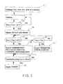
Figure 5 shows the operation of the arrangement. In the arrangement ofFigure 5 , temperature is measured continuously in each stage. Thecalculation unit 2 ofFigure 1 is programmed to display in afield 9, or instruction field, of thedisplay unit 3 "DO NOT ADD WOOD," if themeasuring device 1 measures a temperature Tmv that exceeds 70°C (seeFigure 5 , step 54). At 70°C, five symbols 7 are dark. When the person heating the fireplace receives this notice, s/he does not add wood, but allows the wood in the fireplace to burn out, after which s/he may close the damper (not shown) of the fireplace. Because the temperature of theinner structure 4 of the fireplace is higher than that of theouter stone structure 5, temperature measured from the fireplace rises even if no wood is added. The figure shows that in the example, the temperature rises to the maximum value Tmvmax of 100°C. After about five hours from starting the heating, the fireplace is allowed to cool (seeFigure 3 ). Cooling is slow, because the heat-accumulating mass of the fireplace is great. - A
field 8 of thedisplay unit 3 indicates the measured temperature Tmv as a numerical value and in °C. - The
calculation unit 2, which is a data processor anddisplay unit 3, is programmed to display on theinstruction field 9 of the display unit "HEATING CAN BE RESTARTED," when the temperature Tmv measured from the fireplace has decreased to approximately 40°C (seeFigure 5 , step 57). In the case ofFigure 3 , this takes place approximately 22 hours after starting the heating. Thedisplay unit 3 is adapted to provide said notification at a time and temperature, at which the fireplace is able to receive lots of heat, i.e., it has cooled down substantially, however, before the fireplace has cooled so much that it cannot in practice emit much heat into the environment. When the fireplace is not fully cooled, it is also very easy to light it up again. The temperature, at which it is recommended to start heating again, may be referred to as a second temperature set value T2sv. Its size is selected to be 30 to 50°C depending on how even a heat emission is required of the fireplace. A high value (e.g. 50°C) provides a more even heat emission than a low value (e.g. 30°C). The higher the value T2sv, the more often the fireplace must be re-heated. - If the measured temperature Tmv ≥ T1 sv - ΔT1, wherein T1 sv is a temperature set value and ΔT1 is a so-called first safety margin, the
display unit 3 displays "DO NOT ADD WOOD" (seeFigure 5 , step 54). The temperature set value T1sv and safety margin ΔT1 must be defined and set in the arrangement (seeFigure 5 , step 51) so that the arrangement knows at which temperature Tmv to warn about adding wood. The sizes of the temperature set value T1 sv and safety margin ΔT1 depend mainly on the structure, mass and material of the fireplace. A suitable temperature set value T1sv for a soapstone fireplace is 70°C to 90°C, and a suitable safety margin ΔT1 value is 0.15 to 0.25 x T1sv. If 90°C is selected as the T1sv set value and 0.2 x T1sv as the safety margin ΔT1, this calculates into Tmv = 90°C - 0.2 x 90°C = 72°C, that is, the arrangement warns against adding wood when Tmv ≥ 72°C (seeFigure 5 , steps 53 and 54). Defining the temperature set value T1sv will be discussed in more detail later. - The first safety margin ΔT1 may be defined by monitoring the rate of temperature increase. The increase rate may easily be defined by comparing the prevailing temperature with a value measured earlier and by checking the temperature curve of
Figure 3 . The rate of temperature increase is fireplace-specific and depends mainly on the type, manufacturing material and mass of the fireplace. Temperature increase may be foreseen by multiplying the rate of temperature increase (degrees / time unit) by a fireplace-specific coefficient (time). The coefficient(s) may be determined by experimentation. The system could also be self-learning in such a manner, for instance, that during the learning stage, as a specific temperature is exceeded, the processor provides a signal not to add more wood (see the above "DO NOT ADD WOOD"), after which the processor 1) defines a gradient, 2) observes how much the temperature will rise from this, and 3) stores the data into a memory. During future heating times, the processor may 1) monitor the gradient, 2) on the basis of the gradient, fetch from the stored history data information on how much the temperature will rise from the present, and 3) subtract the temperature increase prediction from a "safe" maximum temperature. When it is estimated on the basis of the gradient and history that a safe maximum temperature will be reached, a signal is provided not to add more wood ("DO NOT ADD WOOD"). - If the fireplace is repeatedly heated by adding a furnace-full or more wood against the instructions of the
display unit 3, the fireplace will overheat repeatedly and its service life will shorten. During overheating, the temperature of theinner stone structure 4 increases above its long-term durability. A seldom occurring slight overheating is not very dangerous. The dashed line inFigure 3 shows a situation, in which a furnace-full of wood has been added into the fireplace - against the instructions of the display unit 3 - when the temperature of the outer shell structure is 90°C. Adding wood increases the temperature of theouter shell structure 5 to Tmvmax 120°C. This is 20°C above the temperature that the fireplace can endure for certain, because the curve marked by a uniform line inFigure 3 represents the correct maximum heat accumulation that indicates 100°C as the maximum temperature Tmvmax. - The condition of the fireplace should be checked and necessary maintenance work done to it, if it has been overheated repeatedly. For the purpose of indicating that the fireplace possibly requires maintenance and should be checked, the arrangement calculates cumulatively the overheating time, tl, that is, how long the fireplace has been overheated (see
Figure 5 , step 59). Afield 10 in thedisplay unit 3 shows the overheating time in hours. Calculating the overheating time tl will be started when the measured temperature Tmv is higher by a second safety margin ΔT2 than the temperature set value T1sv (seeFigure 5 , steps 55, 58). The size of the second safety margin is preferably selected to be ΔT2 = 0.1...0.2 x temperature set value T1sv. Accordingly, if the temperature set value T1 sv is selected to be 90°C and the second safety margin ΔT2 is selected to be 0.15 x 90°C = 13.5°C, the calculation of the overheating time tc will be started when the measured temperature is 90 + 13.5 = 103.5°C. When the overheating time tc exceeds a limit value tl of 50 hours, thedisplay unit 3 of the arrangement displays in afield 11 "CHECK" and/or the arrangement emits an audio signal (seeFigure 5 , steps 59, 60). The value of the safety margin ΔT2 and especially the temperature set value T1sv depend on the location of the measuringdevice 1 and must be selected accordingly. The location where the measuring device is mounted represents the fireplace only when the shape of the heating curve is examined; the location does not represent absolute temperature values. Depending on the mounting location and fireplace, it is possible that in one case a certain temperature indicates a general overheating, even though in another case a temperature higher than this does not necessarily indicate overheating. - The arrangement is switched on and off using a
button 12 in thedisplay unit 3; the required temperature set values T1sv and T2sv may be programmed withbuttons 13 and 15 (reset button). The programming is not described in detail herein, because it does not require any special expertise. - The arrangement goes into learning state by pressing a
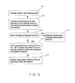
button 14 of the display unit (seeFigure 4 , andFigure 6 , step 61). The purpose of the learning state is to define a suitable temperature set value T1sv. This is done according toFigure 6 ,step 62, in such a manner that the person heating the fireplace attempts to heat it correctly to accumulate as high an amount of heat as possible. Correct heating means that the fireplace is heated in a conventional manner with wood containing a conventional heat value without overheating it in such a manner that its strength suffers. Preferably, the instructions for use of the manufacturer assist in correct heating. A person skilled in the art is familiar with correct heating. The success of the heating is evaluated by measuring the temperature and comparing the measured temperatures with those allowed that do not overheat the fireplace (seeFigure 6 , step 63). The temperatures are stored into amemory 17 of the arrangement that is arranged to thecalculation unit 2. If heating is not successful, the temperatures/heat curves are deleted from thememory 17 of the arrangement (seeFigure 6 , step 66); if heating is successful, the temperature set value T1 sv is defined by selecting as its value the maximum temperature Tmvmax measured from theouter shell 5 minus the safety margin = 10°C to 20°C, and this is stored into thememory 17 of the arrangement (seeFigure 6 , step 64). If during correct and successful heating it is noted that the temperature of the outer shell increases to the maximum value of 90°C, for instance, the temperature set value T1 sv is selected to be 90°C minus the safety margin. If the safety margin is selected to be 15°C, the temperature set value becomes 75°C. When the temperature set value T1sv has been defined, and the actions according toFigure 5 need to be performed, the temperature set value T1sv is fetched from thememory 17 of the arrangement (seeFigure 6 , step 65). A person skilled in the art is capable of evaluating the success of the heating. - The
button 15 in the display unit is a reset button that is used when programming the arrangement. - A few temperature set values and safety margins that form different programs may be stored into the arrangement. One program provides a very even heat emission, whereas another program provides a more uneven heat emission. The former program requires that the re-heating of the fireplace be done relatively often. The required program may be selected by pressing a
menu button 16 of thedisplay unit 3. - In the above, the invention is described by means of examples, wherefore it is noted that the details of the invention may be implemented in various ways within the scope of the attached claims. The temperature set values, safety margins sizes, and counter limit value may also be selected specifically for each fireplace. Instead of firewood, it is possible to use some other fuel, such as pellets, to heat the fireplace. In the example, the calculation unit is described as a programmed data processor, but it may also be implemented by dedicated logic. The amount of information provided by the
display unit 3 may vary, as may the presentation of the information (graphical, numeric, audio, or light information, etc.). The fireplace does not necessarily need to comprise an outer shell separate from the inner stone structure, even though this is highly recommended. The manufacturing material of the fireplace does not need to be stone, but may be some other material.
Claims (18)
- An arrangement in a heat-accumulating fireplace, the arrangement comprising a measuring device (1) that is arranged to react to temperature changes and that is arranged to the heat-accumulating structure of the fireplace and intended to control the use of the fireplace, characterised in that the arrangement comprises an electric calculation unit (2) coupled to a display unit (3) and arranged to display data representing the heat accumulation status of the fireplace in response to temperature changes detected by the measuring device (1) and to inform the user of the fireplace, when the fireplace has reached its maximum and correct heat accumulation, that there is a danger of overheating the fireplace, if fuel is added.
- An arrangement as claimed in claim 1, characterised in that the heat-accumulating structure comprises a massive heat-accumulating inner structure (4) and an outer shell structure (5) and that the measuring device (1) is arranged in the outer shell structure (5).
- An arrangement as claimed in claim 2, characterised in that there is an air gap (6) between the outer shell structure (5) and inner structure (4).
- An arrangement as claimed in claim 3, characterised in that a smoke flue forms the air gap (6).
- An arrangement as claimed in any one of preceding claims 1 to 4, c h a r a c t e r i s e d in that the display unit (3) is arranged to show the heat accumulation status of the fireplace by using graphical data.
- An arrangement as claimed in any one of the preceding claims, characterised in that the calculation unit (2) is arranged to- retain in a memory (51) a temperature set value T1 sv,- monitor (53) a temperature Tmv of the heat-accumulating structure (5) of the fireplace by means of the measuring device (1),- compare (53) the temperature Tmv of the structure with the temperature set value T1sv, and- produce (54), in response to the temperature Tmv of the structure being higher than the temperature set value T1sv minus a first safety margin ΔT1, through the display unit a signal to stop adding fuel, which shows that the fireplace has accumulated heat to the extent that more fuel shall not be added.
- An arrangement as claimed in claim 6, characterised in that the first safety margin ΔT1 is selected to be 0.15 to 0.25 x the temperature set value T1 sv in °C.
- An arrangement as claimed in claim 6 or 7, characterised in that the temperature set value T1 sv is selected to be 50 to 100°C.
- An arrangement as claimed in any one of preceding claims 6 to 8, characterised in that the calculation unit (2) is arranged to compare (55) the temperature Tmv of the structure with the temperature set value T1 sv, and in response to the temperature Tmv of the structure being higher than the temperature set value T1sv plus a second safety margin AT2 to produce (58) through the display unit (3) a signal indicating the overheating of the fireplace.
- An arrangement as claimed in claim 9, characterised in that the calculation unit (2) is arranged to calculate (58) cumulatively the time when the fireplace has been overheated, to compare (59) the cumulatively calculated time tc with a time limit tl and, in response to the cumulatively calculated time tc exceeding the time limit tl, to produce (60) through the display unit (3) a signal indicating a need to check the fireplace.
- An arrangement as claimed in claim 10, characterised in that the display unit (3) is arranged to display the cumulatively calculated time tc the fireplace has been overheated.
- An arrangement as claimed in any one of preceding claims 9 to 11, characterised in that the second safety margin ΔT2 is selected to be 0.10 to 0.20 x the temperature set value T1 sv in °C.
- An arrangement as claimed in any one of preceding claims 6 to 12, characterised in that the calculation unit (2) is further arranged to- retain in the memory (51) a second temperature set value T2sv,- monitor the temperature Tmv of the heat-accumulating structure (5) of the fireplace by means of the measuring device (1),- compare (56) the temperature Tmv of the structure with the second temperature set value T2sv, and- in response to the temperature Tmv of the structure being lower than the second temperature set value T2sv to produce (57) through the display unit (3) a signal indicating the start of re-heating the fireplace.
- An arrangement as claimed in claim 13, characterised in that the second temperature set value T2sv is selected to be 30 to 50°C.
- An arrangement as claimed in any one of preceding claims 6 to 14, characterised in that it comprises definition means for defining a temperature set value Tsv specifically for each fireplace, the definition means comprising a memory (17) for storing the heating result of the fireplace that is obtained by heating the fireplace in batches with solid fuel having a conventional heat value by using conventional and correct heating with the aim of obtaining maximum heat accumulation of the fireplace, the definition means comprising- means for monitoring the heating result by measuring the temperature Tmv of the heat-accumulating structure (5) of the fireplace by means of the measuring device (1) and for storing (62) the highest measured temperature Tmvmax into the memory (17) of the arrangement,- means for evaluating (63) the heating result and, in response to the heating not corresponding to said aim, for deleting the stored value (66) from the memory (17) of the arrangement and, if the heating corresponds to said aim, for defining (64) on the basis of the stored highest measured temperature Tmvmax a temperature set value T1sv by selecting (64) as its value a temperature that is 10°C to 20°C below the highest measured temperature Tmvmax and for storing (64) it into the memory (17) of the arrangement.
- An arrangement as claimed in claim 6, characterised in that the calculation unit (2) is arranged to- monitor the increase rate of the temperature Tmv of the structure,
and- use the increase rate of the temperature Tmv of the structure in defining the first safety margin ΔT1. - An arrangement as claimed in claim 16, characterised in that for defining the first safety margin ΔT1, the calculation unit (2) comprises means for multiplying the temperature increase rate by a fireplace-specific coefficient.
- An arrangement as claimed in claim 16, characterised in that for defining the first safety margin ΔT1 the calculation unit (2) comprises- means for storing into the memory (17) several values for the temperature increase rate at the time of providing the signal to stop adding fuel,- means for storing into the memory (17) for each stored temperature increase rate value, how long the temperature will continue to increase after the time the signal to stop adding fuel is given, and- means for defining the first safety margin ΔT1 on the basis of the temperature increase rate and said data stored into the memory (17).
Applications Claiming Priority (1)
| Application Number | Priority Date | Filing Date | Title |
|---|---|---|---|
| FI20105029A FI122198B (en) | 2010-01-15 | 2010-01-15 | Arrangement in an accumulating fireplace |
Publications (3)
| Publication Number | Publication Date |
|---|---|
| EP2345848A1 true EP2345848A1 (en) | 2011-07-20 |
| EP2345848A9 EP2345848A9 (en) | 2011-10-05 |
| EP2345848B1 EP2345848B1 (en) | 2016-04-06 |
Family
ID=41620867
Family Applications (1)
| Application Number | Title | Priority Date | Filing Date |
|---|---|---|---|
| EP11150911.3A Active EP2345848B1 (en) | 2010-01-15 | 2011-01-14 | Arrangement in heat-accumulating fireplace |
Country Status (2)
| Country | Link |
|---|---|
| EP (1) | EP2345848B1 (en) |
| FI (1) | FI122198B (en) |
Cited By (2)
| Publication number | Priority date | Publication date | Assignee | Title |
|---|---|---|---|---|
| WO2015104021A1 (en) * | 2014-01-07 | 2015-07-16 | Aduro A/S | Wood-burning stove combustion monitoring system |
| EP2682674A3 (en) * | 2012-07-03 | 2015-09-23 | Hans Matthiessen | Method for operating a combustion unit and combustion unit |
Citations (5)
| Publication number | Priority date | Publication date | Assignee | Title |
|---|---|---|---|---|
| US4712095A (en) * | 1986-08-01 | 1987-12-08 | Georgis Ii Paul F | Remote temperature alarm for stoves |
| US4901059A (en) * | 1988-12-27 | 1990-02-13 | Amann Matthew J | Overheat warning for wood stoves |
| AT390832B (en) | 1987-03-16 | 1990-07-10 | Kloss Erich | Tiled-base stove |
| EP1376014A2 (en) * | 2002-06-20 | 2004-01-02 | Nunnanlahden Uuni Oy | Heating stove type fireplace |
| US20070289589A1 (en) * | 2006-06-15 | 2007-12-20 | Mcfarland Daniel T | Intelligent and adaptive control system and method for wood burning stove |
-
2010
- 2010-01-15 FI FI20105029A patent/FI122198B/en active IP Right Grant
-
2011
- 2011-01-14 EP EP11150911.3A patent/EP2345848B1/en active Active
Patent Citations (5)
| Publication number | Priority date | Publication date | Assignee | Title |
|---|---|---|---|---|
| US4712095A (en) * | 1986-08-01 | 1987-12-08 | Georgis Ii Paul F | Remote temperature alarm for stoves |
| AT390832B (en) | 1987-03-16 | 1990-07-10 | Kloss Erich | Tiled-base stove |
| US4901059A (en) * | 1988-12-27 | 1990-02-13 | Amann Matthew J | Overheat warning for wood stoves |
| EP1376014A2 (en) * | 2002-06-20 | 2004-01-02 | Nunnanlahden Uuni Oy | Heating stove type fireplace |
| US20070289589A1 (en) * | 2006-06-15 | 2007-12-20 | Mcfarland Daniel T | Intelligent and adaptive control system and method for wood burning stove |
Cited By (2)
| Publication number | Priority date | Publication date | Assignee | Title |
|---|---|---|---|---|
| EP2682674A3 (en) * | 2012-07-03 | 2015-09-23 | Hans Matthiessen | Method for operating a combustion unit and combustion unit |
| WO2015104021A1 (en) * | 2014-01-07 | 2015-07-16 | Aduro A/S | Wood-burning stove combustion monitoring system |
Also Published As
| Publication number | Publication date |
|---|---|
| FI20105029A0 (en) | 2010-01-15 |
| FI20105029L (en) | 2011-07-16 |
| EP2345848B1 (en) | 2016-04-06 |
| EP2345848A9 (en) | 2011-10-05 |
| FI122198B (en) | 2011-10-14 |
Similar Documents
| Publication | Publication Date | Title |
|---|---|---|
| JP7583912B2 (en) | Refrigerant charging system and method | |
| TR201802701T4 (en) | A method and device for monitoring the safe use of a furnace. | |
| US10181245B2 (en) | Dryer vent monitoring device | |
| CN114370953B (en) | Temperature measuring device, terminal, control method and device thereof, and readable storage medium | |
| CN108506963B (en) | Range hood, control method and system thereof, and fire-off detection method and device | |
| US20070289589A1 (en) | Intelligent and adaptive control system and method for wood burning stove | |
| EP2345848B1 (en) | Arrangement in heat-accumulating fireplace | |
| CN115046294A (en) | Auxiliary electric heating control method and device for air conditioner and electronic equipment | |
| CN106403195A (en) | Control method and device for electric auxiliary heating device of air conditioner | |
| JP2009144964A (en) | Range food | |
| JP2006242021A (en) | Abnormality diagnostic device | |
| US10215438B2 (en) | System and method of determining a limit fault in an HVAC unit | |
| US11079139B2 (en) | Water heater blower leakage detection | |
| TWM570400U (en) | Range hood with thermal image detection | |
| CN112303820B (en) | Overload protection detection control method, computer readable storage medium and air conditioner | |
| JP2008195760A (en) | Coal state-managing system | |
| US11619553B2 (en) | Advanced safety mechanisms in an intelligent dry block calibrator | |
| CN114370703A (en) | Gas water heater and secondary pressure adjusting method, adjusting device and storage medium thereof | |
| CN110513822B (en) | Air conditioner control method, storage medium and air conditioner | |
| CN216315123U (en) | Baking device and baking system | |
| KR101247669B1 (en) | Hot water heater and method for preventing overheating of hot water heater | |
| KR101466861B1 (en) | Method for Control of Convection Fan of Steam Oven | |
| JP6173255B2 (en) | Device operation information storage control device | |
| RU230796U1 (en) | DEVICE FOR DETERMINING FIRE HAZARD OF STOVE PIPES | |
| CN112782219A (en) | Method and device for detecting ventilation performance of ventilation pipe, storage medium and warming blanket |
Legal Events
| Date | Code | Title | Description |
|---|---|---|---|
| PUAI | Public reference made under article 153(3) epc to a published international application that has entered the european phase |
Free format text: ORIGINAL CODE: 0009012 |
|
| AK | Designated contracting states |
Kind code of ref document: A1 Designated state(s): AL AT BE BG CH CY CZ DE DK EE ES FI FR GB GR HR HU IE IS IT LI LT LU LV MC MK MT NL NO PL PT RO RS SE SI SK SM TR |
|
| AX | Request for extension of the european patent |
Extension state: BA ME |
|
| 17P | Request for examination filed |
Effective date: 20120116 |
|
| GRAP | Despatch of communication of intention to grant a patent |
Free format text: ORIGINAL CODE: EPIDOSNIGR1 |
|
| INTG | Intention to grant announced |
Effective date: 20151013 |
|
| GRAS | Grant fee paid |
Free format text: ORIGINAL CODE: EPIDOSNIGR3 |
|
| GRAA | (expected) grant |
Free format text: ORIGINAL CODE: 0009210 |
|
| AK | Designated contracting states |
Kind code of ref document: B1 Designated state(s): AL AT BE BG CH CY CZ DE DK EE ES FI FR GB GR HR HU IE IS IT LI LT LU LV MC MK MT NL NO PL PT RO RS SE SI SK SM TR |
|
| REG | Reference to a national code |
Ref country code: GB Ref legal event code: FG4D |
|
| REG | Reference to a national code |
Ref country code: AT Ref legal event code: REF Ref document number: 788250 Country of ref document: AT Kind code of ref document: T Effective date: 20160415 Ref country code: CH Ref legal event code: EP |
|
| REG | Reference to a national code |
Ref country code: IE Ref legal event code: FG4D |
|
| REG | Reference to a national code |
Ref country code: DE Ref legal event code: R096 Ref document number: 602011024802 Country of ref document: DE |
|
| REG | Reference to a national code |
Ref country code: NL Ref legal event code: FP |
|
| REG | Reference to a national code |
Ref country code: SE Ref legal event code: TRGR |
|
| REG | Reference to a national code |
Ref country code: LT Ref legal event code: MG4D |
|
| PG25 | Lapsed in a contracting state [announced via postgrant information from national office to epo] |
Ref country code: PL Free format text: LAPSE BECAUSE OF FAILURE TO SUBMIT A TRANSLATION OF THE DESCRIPTION OR TO PAY THE FEE WITHIN THE PRESCRIBED TIME-LIMIT Effective date: 20160406 Ref country code: FI Free format text: LAPSE BECAUSE OF FAILURE TO SUBMIT A TRANSLATION OF THE DESCRIPTION OR TO PAY THE FEE WITHIN THE PRESCRIBED TIME-LIMIT Effective date: 20160406 Ref country code: LT Free format text: LAPSE BECAUSE OF FAILURE TO SUBMIT A TRANSLATION OF THE DESCRIPTION OR TO PAY THE FEE WITHIN THE PRESCRIBED TIME-LIMIT Effective date: 20160406 Ref country code: NO Free format text: LAPSE BECAUSE OF FAILURE TO SUBMIT A TRANSLATION OF THE DESCRIPTION OR TO PAY THE FEE WITHIN THE PRESCRIBED TIME-LIMIT Effective date: 20160706 Ref country code: IS Free format text: LAPSE BECAUSE OF FAILURE TO SUBMIT A TRANSLATION OF THE DESCRIPTION OR TO PAY THE FEE WITHIN THE PRESCRIBED TIME-LIMIT Effective date: 20160806 |
|
| PG25 | Lapsed in a contracting state [announced via postgrant information from national office to epo] |
Ref country code: ES Free format text: LAPSE BECAUSE OF FAILURE TO SUBMIT A TRANSLATION OF THE DESCRIPTION OR TO PAY THE FEE WITHIN THE PRESCRIBED TIME-LIMIT Effective date: 20160406 Ref country code: RS Free format text: LAPSE BECAUSE OF FAILURE TO SUBMIT A TRANSLATION OF THE DESCRIPTION OR TO PAY THE FEE WITHIN THE PRESCRIBED TIME-LIMIT Effective date: 20160406 Ref country code: PT Free format text: LAPSE BECAUSE OF FAILURE TO SUBMIT A TRANSLATION OF THE DESCRIPTION OR TO PAY THE FEE WITHIN THE PRESCRIBED TIME-LIMIT Effective date: 20160808 Ref country code: GR Free format text: LAPSE BECAUSE OF FAILURE TO SUBMIT A TRANSLATION OF THE DESCRIPTION OR TO PAY THE FEE WITHIN THE PRESCRIBED TIME-LIMIT Effective date: 20160707 Ref country code: LV Free format text: LAPSE BECAUSE OF FAILURE TO SUBMIT A TRANSLATION OF THE DESCRIPTION OR TO PAY THE FEE WITHIN THE PRESCRIBED TIME-LIMIT Effective date: 20160406 Ref country code: HR Free format text: LAPSE BECAUSE OF FAILURE TO SUBMIT A TRANSLATION OF THE DESCRIPTION OR TO PAY THE FEE WITHIN THE PRESCRIBED TIME-LIMIT Effective date: 20160406 |
|
| REG | Reference to a national code |
Ref country code: DE Ref legal event code: R097 Ref document number: 602011024802 Country of ref document: DE |
|
| REG | Reference to a national code |
Ref country code: FR Ref legal event code: PLFP Year of fee payment: 7 |
|
| PG25 | Lapsed in a contracting state [announced via postgrant information from national office to epo] |
Ref country code: SK Free format text: LAPSE BECAUSE OF FAILURE TO SUBMIT A TRANSLATION OF THE DESCRIPTION OR TO PAY THE FEE WITHIN THE PRESCRIBED TIME-LIMIT Effective date: 20160406 Ref country code: RO Free format text: LAPSE BECAUSE OF FAILURE TO SUBMIT A TRANSLATION OF THE DESCRIPTION OR TO PAY THE FEE WITHIN THE PRESCRIBED TIME-LIMIT Effective date: 20160406 Ref country code: CZ Free format text: LAPSE BECAUSE OF FAILURE TO SUBMIT A TRANSLATION OF THE DESCRIPTION OR TO PAY THE FEE WITHIN THE PRESCRIBED TIME-LIMIT Effective date: 20160406 Ref country code: DK Free format text: LAPSE BECAUSE OF FAILURE TO SUBMIT A TRANSLATION OF THE DESCRIPTION OR TO PAY THE FEE WITHIN THE PRESCRIBED TIME-LIMIT Effective date: 20160406 Ref country code: EE Free format text: LAPSE BECAUSE OF FAILURE TO SUBMIT A TRANSLATION OF THE DESCRIPTION OR TO PAY THE FEE WITHIN THE PRESCRIBED TIME-LIMIT Effective date: 20160406 |
|
| PLBE | No opposition filed within time limit |
Free format text: ORIGINAL CODE: 0009261 |
|
| STAA | Information on the status of an ep patent application or granted ep patent |
Free format text: STATUS: NO OPPOSITION FILED WITHIN TIME LIMIT |
|
| PG25 | Lapsed in a contracting state [announced via postgrant information from national office to epo] |
Ref country code: SM Free format text: LAPSE BECAUSE OF FAILURE TO SUBMIT A TRANSLATION OF THE DESCRIPTION OR TO PAY THE FEE WITHIN THE PRESCRIBED TIME-LIMIT Effective date: 20160406 |
|
| 26N | No opposition filed |
Effective date: 20170110 |
|
| PG25 | Lapsed in a contracting state [announced via postgrant information from national office to epo] |
Ref country code: SI Free format text: LAPSE BECAUSE OF FAILURE TO SUBMIT A TRANSLATION OF THE DESCRIPTION OR TO PAY THE FEE WITHIN THE PRESCRIBED TIME-LIMIT Effective date: 20160406 |
|
| REG | Reference to a national code |
Ref country code: CH Ref legal event code: PL |
|
| PG25 | Lapsed in a contracting state [announced via postgrant information from national office to epo] |
Ref country code: MC Free format text: LAPSE BECAUSE OF FAILURE TO SUBMIT A TRANSLATION OF THE DESCRIPTION OR TO PAY THE FEE WITHIN THE PRESCRIBED TIME-LIMIT Effective date: 20160406 |
|
| PG25 | Lapsed in a contracting state [announced via postgrant information from national office to epo] |
Ref country code: LI Free format text: LAPSE BECAUSE OF NON-PAYMENT OF DUE FEES Effective date: 20170131 Ref country code: CH Free format text: LAPSE BECAUSE OF NON-PAYMENT OF DUE FEES Effective date: 20170131 |
|
| REG | Reference to a national code |
Ref country code: IE Ref legal event code: MM4A |
|
| PG25 | Lapsed in a contracting state [announced via postgrant information from national office to epo] |
Ref country code: LU Free format text: LAPSE BECAUSE OF NON-PAYMENT OF DUE FEES Effective date: 20170114 |
|
| REG | Reference to a national code |
Ref country code: FR Ref legal event code: PLFP Year of fee payment: 8 |
|
| PG25 | Lapsed in a contracting state [announced via postgrant information from national office to epo] |
Ref country code: IE Free format text: LAPSE BECAUSE OF NON-PAYMENT OF DUE FEES Effective date: 20170114 |
|
| PGFP | Annual fee paid to national office [announced via postgrant information from national office to epo] |
Ref country code: NL Payment date: 20180123 Year of fee payment: 8 |
|
| PGFP | Annual fee paid to national office [announced via postgrant information from national office to epo] |
Ref country code: DE Payment date: 20180123 Year of fee payment: 8 |
|
| PGFP | Annual fee paid to national office [announced via postgrant information from national office to epo] |
Ref country code: BE Payment date: 20180124 Year of fee payment: 8 Ref country code: FR Payment date: 20180122 Year of fee payment: 8 Ref country code: AT Payment date: 20180123 Year of fee payment: 8 Ref country code: IT Payment date: 20180129 Year of fee payment: 8 |
|
| PG25 | Lapsed in a contracting state [announced via postgrant information from national office to epo] |
Ref country code: MT Free format text: LAPSE BECAUSE OF NON-PAYMENT OF DUE FEES Effective date: 20170114 |
|
| PG25 | Lapsed in a contracting state [announced via postgrant information from national office to epo] |
Ref country code: AL Free format text: LAPSE BECAUSE OF FAILURE TO SUBMIT A TRANSLATION OF THE DESCRIPTION OR TO PAY THE FEE WITHIN THE PRESCRIBED TIME-LIMIT Effective date: 20160406 |
|
| PGFP | Annual fee paid to national office [announced via postgrant information from national office to epo] |
Ref country code: GB Payment date: 20190115 Year of fee payment: 9 |
|
| PG25 | Lapsed in a contracting state [announced via postgrant information from national office to epo] |
Ref country code: HU Free format text: LAPSE BECAUSE OF FAILURE TO SUBMIT A TRANSLATION OF THE DESCRIPTION OR TO PAY THE FEE WITHIN THE PRESCRIBED TIME-LIMIT; INVALID AB INITIO Effective date: 20110114 |
|
| REG | Reference to a national code |
Ref country code: AT Ref legal event code: UEP Ref document number: 788250 Country of ref document: AT Kind code of ref document: T Effective date: 20160406 |
|
| REG | Reference to a national code |
Ref country code: DE Ref legal event code: R119 Ref document number: 602011024802 Country of ref document: DE |
|
| PG25 | Lapsed in a contracting state [announced via postgrant information from national office to epo] |
Ref country code: BG Free format text: LAPSE BECAUSE OF FAILURE TO SUBMIT A TRANSLATION OF THE DESCRIPTION OR TO PAY THE FEE WITHIN THE PRESCRIBED TIME-LIMIT Effective date: 20160406 |
|
| REG | Reference to a national code |
Ref country code: NL Ref legal event code: MM Effective date: 20190201 |
|
| REG | Reference to a national code |
Ref country code: AT Ref legal event code: MM01 Ref document number: 788250 Country of ref document: AT Kind code of ref document: T Effective date: 20190114 |
|
| REG | Reference to a national code |
Ref country code: BE Ref legal event code: MM Effective date: 20190131 |
|
| PG25 | Lapsed in a contracting state [announced via postgrant information from national office to epo] |
Ref country code: NL Free format text: LAPSE BECAUSE OF NON-PAYMENT OF DUE FEES Effective date: 20190201 Ref country code: DE Free format text: LAPSE BECAUSE OF NON-PAYMENT OF DUE FEES Effective date: 20190801 Ref country code: FR Free format text: LAPSE BECAUSE OF NON-PAYMENT OF DUE FEES Effective date: 20190131 Ref country code: CY Free format text: LAPSE BECAUSE OF NON-PAYMENT OF DUE FEES Effective date: 20160406 |
|
| PG25 | Lapsed in a contracting state [announced via postgrant information from national office to epo] |
Ref country code: BE Free format text: LAPSE BECAUSE OF NON-PAYMENT OF DUE FEES Effective date: 20190131 Ref country code: MK Free format text: LAPSE BECAUSE OF FAILURE TO SUBMIT A TRANSLATION OF THE DESCRIPTION OR TO PAY THE FEE WITHIN THE PRESCRIBED TIME-LIMIT Effective date: 20160406 |
|
| PG25 | Lapsed in a contracting state [announced via postgrant information from national office to epo] |
Ref country code: AT Free format text: LAPSE BECAUSE OF NON-PAYMENT OF DUE FEES Effective date: 20190114 |
|
| PG25 | Lapsed in a contracting state [announced via postgrant information from national office to epo] |
Ref country code: IT Free format text: LAPSE BECAUSE OF NON-PAYMENT OF DUE FEES Effective date: 20190114 |
|
| PG25 | Lapsed in a contracting state [announced via postgrant information from national office to epo] |
Ref country code: TR Free format text: LAPSE BECAUSE OF FAILURE TO SUBMIT A TRANSLATION OF THE DESCRIPTION OR TO PAY THE FEE WITHIN THE PRESCRIBED TIME-LIMIT Effective date: 20160406 |
|
| GBPC | Gb: european patent ceased through non-payment of renewal fee |
Effective date: 20200114 |
|
| PG25 | Lapsed in a contracting state [announced via postgrant information from national office to epo] |
Ref country code: GB Free format text: LAPSE BECAUSE OF NON-PAYMENT OF DUE FEES Effective date: 20200114 |
|
| PGFP | Annual fee paid to national office [announced via postgrant information from national office to epo] |
Ref country code: SE Payment date: 20260122 Year of fee payment: 16 |