EP2345805A1 - Inlet air heating and cooling system for the compressor of a gasturbine - Google Patents
Inlet air heating and cooling system for the compressor of a gasturbine Download PDFInfo
- Publication number
- EP2345805A1 EP2345805A1 EP09177609A EP09177609A EP2345805A1 EP 2345805 A1 EP2345805 A1 EP 2345805A1 EP 09177609 A EP09177609 A EP 09177609A EP 09177609 A EP09177609 A EP 09177609A EP 2345805 A1 EP2345805 A1 EP 2345805A1
- Authority
- EP
- European Patent Office
- Prior art keywords
- fluid
- storage tank
- thermal energy
- energy storage
- coil
- Prior art date
- Legal status (The legal status is an assumption and is not a legal conclusion. Google has not performed a legal analysis and makes no representation as to the accuracy of the status listed.)
- Withdrawn
Links
- 238000001816 cooling Methods 0.000 title claims abstract description 41
- 238000010438 heat treatment Methods 0.000 title claims abstract description 40
- 239000012530 fluid Substances 0.000 claims abstract description 45
- 238000004146 energy storage Methods 0.000 claims abstract description 42
- 238000004891 communication Methods 0.000 claims abstract description 7
- XLYOFNOQVPJJNP-UHFFFAOYSA-N water Substances O XLYOFNOQVPJJNP-UHFFFAOYSA-N 0.000 claims description 65
- 238000000034 method Methods 0.000 claims description 12
- 230000003190 augmentative effect Effects 0.000 claims 1
- 239000003570 air Substances 0.000 description 38
- 239000007789 gas Substances 0.000 description 18
- 239000002918 waste heat Substances 0.000 description 5
- 238000011084 recovery Methods 0.000 description 4
- 238000005057 refrigeration Methods 0.000 description 3
- 239000012080 ambient air Substances 0.000 description 2
- 239000000446 fuel Substances 0.000 description 2
- VNWKTOKETHGBQD-UHFFFAOYSA-N methane Chemical compound C VNWKTOKETHGBQD-UHFFFAOYSA-N 0.000 description 2
- 230000003071 parasitic effect Effects 0.000 description 2
- 238000010521 absorption reaction Methods 0.000 description 1
- 230000002528 anti-freeze Effects 0.000 description 1
- 230000009286 beneficial effect Effects 0.000 description 1
- 239000000567 combustion gas Substances 0.000 description 1
- 230000000694 effects Effects 0.000 description 1
- 239000007788 liquid Substances 0.000 description 1
- 239000000203 mixture Substances 0.000 description 1
- 238000012986 modification Methods 0.000 description 1
- 230000004048 modification Effects 0.000 description 1
- 239000003345 natural gas Substances 0.000 description 1
- 238000010248 power generation Methods 0.000 description 1
Images

Classifications
-
- F—MECHANICAL ENGINEERING; LIGHTING; HEATING; WEAPONS; BLASTING
- F02—COMBUSTION ENGINES; HOT-GAS OR COMBUSTION-PRODUCT ENGINE PLANTS
- F02C—GAS-TURBINE PLANTS; AIR INTAKES FOR JET-PROPULSION PLANTS; CONTROLLING FUEL SUPPLY IN AIR-BREATHING JET-PROPULSION PLANTS
- F02C7/00—Features, components parts, details or accessories, not provided for in, or of interest apart form groups F02C1/00 - F02C6/00; Air intakes for jet-propulsion plants
- F02C7/12—Cooling of plants
- F02C7/14—Cooling of plants of fluids in the plant, e.g. lubricant or fuel
- F02C7/141—Cooling of plants of fluids in the plant, e.g. lubricant or fuel of working fluid
- F02C7/143—Cooling of plants of fluids in the plant, e.g. lubricant or fuel of working fluid before or between the compressor stages
-
- F—MECHANICAL ENGINEERING; LIGHTING; HEATING; WEAPONS; BLASTING
- F02—COMBUSTION ENGINES; HOT-GAS OR COMBUSTION-PRODUCT ENGINE PLANTS
- F02C—GAS-TURBINE PLANTS; AIR INTAKES FOR JET-PROPULSION PLANTS; CONTROLLING FUEL SUPPLY IN AIR-BREATHING JET-PROPULSION PLANTS
- F02C6/00—Plural gas-turbine plants; Combinations of gas-turbine plants with other apparatus; Adaptations of gas-turbine plants for special use
- F02C6/14—Gas-turbine plants having means for storing energy, e.g. for meeting peak loads
-
- F—MECHANICAL ENGINEERING; LIGHTING; HEATING; WEAPONS; BLASTING
- F05—INDEXING SCHEMES RELATING TO ENGINES OR PUMPS IN VARIOUS SUBCLASSES OF CLASSES F01-F04
- F05D—INDEXING SCHEME FOR ASPECTS RELATING TO NON-POSITIVE-DISPLACEMENT MACHINES OR ENGINES, GAS-TURBINES OR JET-PROPULSION PLANTS
- F05D2260/00—Function
- F05D2260/20—Heat transfer, e.g. cooling
Definitions
- the present application relates generally to gas turbine engines and more particularly relates to gas turbine inlet air systems that provide free inlet air heating and cooling.
- Air chilling systems are often used with gas turbines to condition the inlet air temperature.
- the use of the chilling systems with gas turbine engines may increase overall power output by a significant percentage.
- the power output of the gas turbine is almost in reverse proportion to the inlet air temperature over a wide temperature range.
- a known gas turbine may produce only about 154 megawatts of power at an ambient temperature of about 83 degrees Fahrenheit (about 28.3 degrees Celsius) but may produce about 171.2 megawatts of power at about 50 degrees Fahrenheit (about 10 degrees Celsius), an increase of more than about eleven percent.
- the chilling systems may temper the cold inlet air with waste heat in cooler ambient temperatures so as to provide efficient part load operation for the gas turbine.
- Such heating and cooling systems should provide for enhanced heating and cooling of gas turbine inlet air temperatures while increasing overall system power output and efficiency.
- the present application thus provides a heating and cooling system for inlet air of a turbine compressor.
- the heating and cooling system may include a fluid coil positioned about the turbine compressor and a thermal energy storage tank.
- the fluid coil and the thermal energy storage tank are in fluid communication such that fluid is both provided to the fluid coil from the thermal energy storage tank for exchanging heat with the inlet air and returned to the thermal energy storage tank without further heat exchange.
- the present application further provides for a method of free heating and cooling of inlet air of a compressor.
- the method may include the steps of flowing a fluid at a first temperature from a first end of a thermal energy storage tank directly to a coil, exchanging heat in the coil with a first incoming flow of the inlet air such that the fluid reaches a second temperature, flowing the fluid at the second temperature directly to a second end of the thermal energy storage tank, and flowing the fluid from the second end of the thermal energy storage tank directly to the coil to exchange heat with a second incoming flow of the inlet air.
- Fig. 1 shows a schematic view of a gas turbine engine 10.
- the gas turbine engine 10 may include a compressor 20 to compress an incoming flow of air.
- the compressor 20 delivers the compressed flow of air to a combustor 30.
- the combustor 30 mixes the compressed flow of air with a flow of fuel and ignites the mixture.
- the hot combustion gases are delivered in turn to a turbine 40.
- the turbine 40 drives the compressor 20 and an external load 50 such as an electrical generator and the like.
- the gas turbine engine 10 may use natural gas, various types of syngas, and other fuels.
- the gas turbine engine 10 may use other configurations and components herein.
- the gas turbine engine 10 further includes an inlet air heating and cooling system 60.
- the inlet air heating and cooling system 60 may be positioned about the compressor 20 and heats or cools the incoming airflow to a desired temperature.
- the inlet air heating and cooling system 60 includes a cold/hot water coil 70. Hot or cold water flows through the coil 70 and exchanges heat with the incoming airflow.
- the inlet air heating and cooling system 60 may use any type of heat exchange device therein. As described above, cold water may be provided by a water chilling plant while hot water may be provided via a waste heat recovery system or from another source.
- Figs. 2 and 3 show a turbine inlet air heating and cooling system 100 as is described herein. Similar to the system described above, the turbine inlet air heating and cooling system 100 includes a cold/hot water coil 110. As described above, the cold/hot water coil 110 may be positioned about the inlet of the compressor 20. The cold/hot water coil 110 heats or cools the inlet air via a water stream running therethrough. Other types of heat exchange devices may be used herein.
- the cold/hot water coil 110 may be in communication with a water chiller 120.
- the water chiller 120 may be a mechanical chiller, an absorption chiller, or any conventional type of chilling device. As is known, the water chiller 120 provides cold water to the cold/hot water coil 110 where heat is exchanged with the incoming airflow. The warm water is then returned to the water chiller 120.
- the cold/hot water coil 110 may be in communication with the water chiller 120 via a primary loop 130. Hot water from waste heat or another source also may be provided to cold/hot water coil 110 via the primary loop 130.
- the primary loop may include a number of water pumps 140, including a chiller inlet pump 141 and a coil inlet pump 142, and a number of valves 150, including a chiller inlet valve 151 and a coil inlet valve 152, to control the flow of water therethrough.
- the turbine inlet air heating and cooling system 100 also may include a free inlet air heating and cooling system 160.
- the free inlet air heating and cooling system 160 may include a thermal energy storage tank 170.
- the thermal energy storage tank 170 may be a conventional stratified water thermal storage system. Other types of liquids also may be used herein. Warm water rises to a top portion 171 of the tank 170 while cooler water sinks to a bottom portion 172 of the tank 170.
- the thermal energy tank 170 may be in communication with the cold/hot water coil 110 via a secondary loop 180.
- the secondary loop 180 ties into the primary loop 130 via a number of secondary loop valves 190.
- These valves include tank valves 191 and 195, a warm water valve 192, a cold water valve 193, and a bypass valve 194.
- Fig. 2 shows use of the free inlet air heating and cooling system 160 in the heating mode.
- the water chiller 120 is turned off.
- the cold water valve 193 and the tank valve 195 are closed while the tank valve 191, the warm water valve 192, and the bypass valve 194 are open.
- Warm water from the top 171 of the thermal energy storage tank 170 passes through the warm water valve 192 and into the primary loop 130.
- the warm water passes through the cold/hot water coil 110 where it warms the cold incoming air.
- the now colder water flow returns via the primary loop 130, the bypass valve 194, and the tank valve 191 into the bottom 172 of the thermal energy storage tank 170.
- Cold ambient air below about 40 degrees Fahrenheit may be tempered to about 55 degrees Fahrenheit (about 12.8 degrees Celsius) so as to provide efficient part loading that may be beneficial during off peak hours.
- the water passing through the cold/hot water coil 110 will cool down from about 58 degrees Fahrenheit (about 14.4 degrees Celsius) to about 42 degrees Fahrenheit (about 5.6 degrees Celsius).
- the heating mode of the free inlet air heating and cooling system 160 thus heats the incoming airflow without the consumption of external thermal energy.
- the warm water running through the cold/hot water coil 110 also can be used for compressor freeze protection so as to avoid the use of inlet bleed heat. Likewise, the warm water provides freeze protection to the cold/hot water coil 110 as well as the inlet filters without external energy or the use of antifreeze.
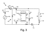
- Fig. 3 shows use of the free inlet air heating and cooling system 160 in cooling mode.
- the water chiller 120 is again turned off.
- the chiller inlet pump 141 is turned off.
- the warm water valve 192 and the bypass valve 194 are closed while the cold water valve 193 and the tank valves 191 and 195 are opened.
- Cold water from the bottom 172 of the thermal energy tank 170 passes through the tank valve 191 and through the cold water valve 193 into the primary loop 130.
- the cold water is then pumped into and through the cold/hot water coil 110.
- the cold water thus cools the warm incoming airflow.
- the now warmer water continues to flow through the primary loop 130 and the tank valve 195 and into the top 171 of the thermal storage tank 170.
- the turbine inlet air heating and cooling system 100 thus may operate in a number of modes: (1) inlet cooling with only the use of the chiller 120; (2) inlet cooling with only the use of the thermal energy storage tank 170; (3) inlet cooling via the combination of the chillers 120 and the thermal energy storage tank 170; (4) charging the thermal energy storage tank 170 using only the chillers 120; (5) inlet heating using waste heat recovery via a heat recovery heat exchanger (not shown); (6) inlet heating using only the charging of the thermal storage tank 170; and (7) inlet heating using the combination of the waste heat from the heat recovery heat exchanger charging of the thermal energy storage tank 170.
- Modes 2 and 6 provide completely free cooling and heating. Other configurations may be used herein. Other types of thermal sources also may be used herein.
- the turbine inlet air heating and cooling system 100 captures and stores the hot or cold energy of the inlet air itself for later efficient use. Significant amounts of free heating and cooling thus may be provided. Likewise, parasitic power may be reduced while overall power generation may be increased.
Landscapes
- Engineering & Computer Science (AREA)
- Chemical & Material Sciences (AREA)
- Combustion & Propulsion (AREA)
- Mechanical Engineering (AREA)
- General Engineering & Computer Science (AREA)
- Heat-Pump Type And Storage Water Heaters (AREA)
- Heat-Exchange Devices With Radiators And Conduit Assemblies (AREA)
- Devices That Are Associated With Refrigeration Equipment (AREA)
- Air Conditioning Control Device (AREA)
Abstract
A heating and cooling system (100) for inlet air of a turbine compressor (20). The heating and cooling system (100) may include a fluid coil (120) positioned about the turbine compressor (20) and a thermal energy storage tank (170). The fluid coil (110) and the thermal energy storage tank (170) are in fluid communication such that fluid is both provided to the fluid coil (110) from the thermal energy storage tank (170) for exchanging heat with the inlet air and returned to the thermal energy storage tank (170) without further heat exchange.
Description
- The present application relates generally to gas turbine engines and more particularly relates to gas turbine inlet air systems that provide free inlet air heating and cooling.
- Air chilling systems are often used with gas turbines to condition the inlet air temperature. Depending upon the ambient temperature, the use of the chilling systems with gas turbine engines may increase overall power output by a significant percentage. Specifically, the power output of the gas turbine is almost in reverse proportion to the inlet air temperature over a wide temperature range. For example, a known gas turbine may produce only about 154 megawatts of power at an ambient temperature of about 83 degrees Fahrenheit (about 28.3 degrees Celsius) but may produce about 171.2 megawatts of power at about 50 degrees Fahrenheit (about 10 degrees Celsius), an increase of more than about eleven percent. Likewise, the chilling systems may temper the cold inlet air with waste heat in cooler ambient temperatures so as to provide efficient part load operation for the gas turbine.
- Known air chilling systems, however, generally use a refrigeration plant to produce cold water. As such, an external energy source is required to run the refrigeration plant. This parasitic power drain thus may compromise somewhat the overall power plant output and efficiency.
- There is thus a desire for improved gas turbine inlet air heating and cooling systems. Such heating and cooling systems should provide for enhanced heating and cooling of gas turbine inlet air temperatures while increasing overall system power output and efficiency.
- The present application thus provides a heating and cooling system for inlet air of a turbine compressor. The heating and cooling system may include a fluid coil positioned about the turbine compressor and a thermal energy storage tank. The fluid coil and the thermal energy storage tank are in fluid communication such that fluid is both provided to the fluid coil from the thermal energy storage tank for exchanging heat with the inlet air and returned to the thermal energy storage tank without further heat exchange.
- The present application further provides for a method of free heating and cooling of inlet air of a compressor. The method may include the steps of flowing a fluid at a first temperature from a first end of a thermal energy storage tank directly to a coil, exchanging heat in the coil with a first incoming flow of the inlet air such that the fluid reaches a second temperature, flowing the fluid at the second temperature directly to a second end of the thermal energy storage tank, and flowing the fluid from the second end of the thermal energy storage tank directly to the coil to exchange heat with a second incoming flow of the inlet air.
- These and other features of the present application will become apparent to one of ordinary skill in the art upon review of the following detailed description when taken in conjunction with the several drawings and the appended claims.
-
-
Fig. 1 is a schematic view of a gas turbine engine with an inlet air chilling system. -
Fig. 2 is a schematic view of a gas turbine inlet air heating and cooling system in heating mode. -
Fig. 3 is a schematic view of a gas turbine inlet air heating and cooling system in cooling mode. - Referring now to the drawings, in which like numerals refer to like elements throughout the several views,
Fig. 1 shows a schematic view of agas turbine engine 10. As is known, thegas turbine engine 10 may include acompressor 20 to compress an incoming flow of air. Thecompressor 20 delivers the compressed flow of air to a combustor 30. The combustor 30 mixes the compressed flow of air with a flow of fuel and ignites the mixture. (Although only a single combustor 30 is shown, thegas turbine engine 10 may include any number of combustors 30.) The hot combustion gases are delivered in turn to a turbine 40. The turbine 40 drives thecompressor 20 and an external load 50 such as an electrical generator and the like. Thegas turbine engine 10 may use natural gas, various types of syngas, and other fuels. Thegas turbine engine 10 may use other configurations and components herein. - In this example, the
gas turbine engine 10 further includes an inlet air heating andcooling system 60. The inlet air heating andcooling system 60 may be positioned about thecompressor 20 and heats or cools the incoming airflow to a desired temperature. The inlet air heating andcooling system 60 includes a cold/hot water coil 70. Hot or cold water flows through thecoil 70 and exchanges heat with the incoming airflow. The inlet air heating andcooling system 60 may use any type of heat exchange device therein. As described above, cold water may be provided by a water chilling plant while hot water may be provided via a waste heat recovery system or from another source. -
Figs. 2 and3 show a turbine inlet air heating andcooling system 100 as is described herein. Similar to the system described above, the turbine inlet air heating andcooling system 100 includes a cold/hot water coil 110. As described above, the cold/hot water coil 110 may be positioned about the inlet of thecompressor 20. The cold/hot water coil 110 heats or cools the inlet air via a water stream running therethrough. Other types of heat exchange devices may be used herein. - The cold/
hot water coil 110 may be in communication with awater chiller 120. Thewater chiller 120 may be a mechanical chiller, an absorption chiller, or any conventional type of chilling device. As is known, thewater chiller 120 provides cold water to the cold/hot water coil 110 where heat is exchanged with the incoming airflow. The warm water is then returned to thewater chiller 120. The cold/hot water coil 110 may be in communication with thewater chiller 120 via aprimary loop 130. Hot water from waste heat or another source also may be provided to cold/hot water coil 110 via theprimary loop 130. The primary loop may include a number ofwater pumps 140, including achiller inlet pump 141 and acoil inlet pump 142, and a number ofvalves 150, including achiller inlet valve 151 and acoil inlet valve 152, to control the flow of water therethrough. - It is important to note that the terms "hot", "warm", "cold", and "cool" are used in a relative sense. No limitation on the applicable temperature range is intended herein.
- The turbine inlet air heating and
cooling system 100 also may include a free inlet air heating andcooling system 160. The free inlet air heating andcooling system 160 may include a thermalenergy storage tank 170. The thermalenergy storage tank 170 may be a conventional stratified water thermal storage system. Other types of liquids also may be used herein. Warm water rises to atop portion 171 of thetank 170 while cooler water sinks to abottom portion 172 of thetank 170. Thethermal energy tank 170 may be in communication with the cold/hot water coil 110 via asecondary loop 180. Thesecondary loop 180 ties into theprimary loop 130 via a number ofsecondary loop valves 190. These valves includetank valves warm water valve 192, acold water valve 193, and abypass valve 194. -
Fig. 2 shows use of the free inlet air heating andcooling system 160 in the heating mode. In this mode, thewater chiller 120 is turned off. Thecold water valve 193 and thetank valve 195 are closed while thetank valve 191, thewarm water valve 192, and thebypass valve 194 are open. Warm water from the top 171 of the thermalenergy storage tank 170 passes through thewarm water valve 192 and into theprimary loop 130. The warm water passes through the cold/hot water coil 110 where it warms the cold incoming air. The now colder water flow returns via theprimary loop 130, thebypass valve 194, and thetank valve 191 into thebottom 172 of the thermalenergy storage tank 170. - Cold ambient air below about 40 degrees Fahrenheit (about 4.4 degrees Celsius) may be tempered to about 55 degrees Fahrenheit (about 12.8 degrees Celsius) so as to provide efficient part loading that may be beneficial during off peak hours. The water passing through the cold/
hot water coil 110 will cool down from about 58 degrees Fahrenheit (about 14.4 degrees Celsius) to about 42 degrees Fahrenheit (about 5.6 degrees Celsius). - The heating mode of the free inlet air heating and
cooling system 160 thus heats the incoming airflow without the consumption of external thermal energy. The warm water running through the cold/hot water coil 110 also can be used for compressor freeze protection so as to avoid the use of inlet bleed heat. Likewise, the warm water provides freeze protection to the cold/hot water coil 110 as well as the inlet filters without external energy or the use of antifreeze. -
Fig. 3 shows use of the free inlet air heating andcooling system 160 in cooling mode. In this mode, thewater chiller 120 is again turned off. Likewise, thechiller inlet pump 141 is turned off. Thewarm water valve 192 and thebypass valve 194 are closed while thecold water valve 193 and thetank valves bottom 172 of thethermal energy tank 170 passes through thetank valve 191 and through thecold water valve 193 into theprimary loop 130. The cold water is then pumped into and through the cold/hot water coil 110. The cold water thus cools the warm incoming airflow. The now warmer water continues to flow through theprimary loop 130 and thetank valve 195 and into the top 171 of thethermal storage tank 170. - When the ambient air is about 62 degrees Fahrenheit (about 16.7 degrees Celsius), discharged cold water at about 42 degrees Fahrenheit (about 5.6 degrees Celsius) may cool the ambient airflow to as low as about 45 degrees Fahrenheit (about 7.2 degrees Celsius). The now warmer water flow may return at about 58 degrees Fahrenheit (about 14.4 degrees Celsius). The cooling effect will increase the overall power output during peak demand hours. The cooling mode thus provides chilling of the inlet air without the consumption of refrigeration energy.
- The turbine inlet air heating and
cooling system 100 thus may operate in a number of modes: (1) inlet cooling with only the use of thechiller 120; (2) inlet cooling with only the use of the thermalenergy storage tank 170; (3) inlet cooling via the combination of thechillers 120 and the thermalenergy storage tank 170; (4) charging the thermalenergy storage tank 170 using only thechillers 120; (5) inlet heating using waste heat recovery via a heat recovery heat exchanger (not shown); (6) inlet heating using only the charging of thethermal storage tank 170; and (7) inlet heating using the combination of the waste heat from the heat recovery heat exchanger charging of the thermalenergy storage tank 170. Modes 2 and 6 provide completely free cooling and heating. Other configurations may be used herein. Other types of thermal sources also may be used herein. - The turbine inlet air heating and
cooling system 100 captures and stores the hot or cold energy of the inlet air itself for later efficient use. Significant amounts of free heating and cooling thus may be provided. Likewise, parasitic power may be reduced while overall power generation may be increased. - It should be apparent that the foregoing relates only to certain embodiments of the present application and that numerous changes and modifications may be made herein by one of ordinary skill in the art without departing from the general spirit and scope of the invention as defined by the following claims and the equivalents thereof.
Claims (15)
- A heating and cooling system (100) for inlet air of a turbine compressor (20), comprising:a fluid coil (110) positioned about the turbine compressor (20); anda thermal energy storage tank (170);the fluid coil (110) and the thermal energy storage tank (170) in fluid communication such that fluid is both provided to the fluid coil (110) from the thermal energy storage tank (170) for exchanging heat with the inlet air and returned to the thermal energy storage tank (170) without further heat exchange.
- The heating and cooling system (100) of claim 1, wherein the fluid coil (110) comprises a cold/hot water coil (110).
- The heating and cooling system (100) of claim 1 or claim 2, wherein the thermal energy storage tank (170) comprises a stratified water thermal storage tank (170) with a top (171) and a bottom (172).
- The heating and cooling system (100) of any one of the preceding claims, wherein the fluid coil (100) and the thermal energy storage tank (170) are in fluid communication via a loop (180).
- The heating and cooling system (100) of any one of the preceding claims, further comprising a cold fluid valve (193) positioned on the loop (180) to provide cold fluid from the thermal energy storage tank (170) to the fluid coil (180) and a hot fluid valve (192) positioned on the loop (180) to provide hot fluid from the thermal energy storage tank (170) to the fluid coil (110).
- A method of free heating and cooling of inlet air of a compressor (20), comprising:flowing a fluid at a first temperature from a first end (171, 172) of a thermal energy storage tank (170) directly to a coil (110);exchanging heat in the coil (110) with a first incoming flow of the inlet air such that the fluid reaches a second temperature; andflowing the fluid at the second temperature directly to a second end (171, 172) of the thermal energy storage tank (170); andflowing the fluid from the second end (171, 172) of the thermal energy storage tank (170) directly to the coil (110) to exchange heat with a second incoming flow of the inlet air.
- The method of claim 6, wherein the step of flowing a fluid at a first temperature from a first end (171, 172) of a thermal energy storage tank (170) directly to a coil (110) comprises flowing cool water from the bottom (172) of the thermal energy storage tank (170) to a water coil (110).
- The method of claim 6 or claim 7, wherein the step of exchanging heat in the coil (110) with a first incoming flow of the inlet air such that the fluid reaches a second temperature comprises exchanging heat with a warm incoming flow of the inlet air.
- The method of any one of claims 6 to 8, wherein the step of flowing the fluid at the second temperature directly to a second end of the thermal energy storage tank comprises flowing warm water back to the top of the thermal energy storage tank.
- The method of any one of claims 6 to 9, wherein the step of flowing the fluid from the second end of the thermal energy storage tank directly to the coil to exchange heat with a second incoming flow of the inlet air comprises flowing warm water from the top of the thermal energy storage tank to exchange heat with a cold incoming flow of the inlet air.
- The method of any one of claims 6 to 10, wherein the step of flowing a fluid at a first temperature from a first end (171, 172) of a thermal energy storage tank (170) directly to a coil (110) comprises flowing warm water from the top (171) of the thermal energy storage tank (170) to a water coil (110).
- The method of any one of claims 9 to 11, wherein the step of exchanging heat in the coil (110) with a first incoming flow of the inlet air such that the fluid reaches a second temperature comprises exchanging heat with a cool incoming flow of the inlet air.
- The method of any one of claims 6 to 12, wherein the step of flowing the fluid at the second temperature directly to a second end of the thermal energy storage tank comprises flowing cool water back to the bottom of the thermal energy storage tank.
- The method of any one of claims 6 to 13, wherein the step of flowing the fluid from the second end of the thermal energy storage tank directly to the coil to exchange heat with a second incoming flow of the inlet air comprises flowing cool water from the bottom of the thermal energy storage tank to exchange heat with a warm incoming flow of the inlet air.
- The method of any one of claims 6 to 14, further comprising chilling a further fluid in a fluid source, flowing the further fluid to the coil, and augmenting the further fluid with the fluid at the first temperature.
Applications Claiming Priority (1)
| Application Number | Priority Date | Filing Date | Title |
|---|---|---|---|
| US12/332,380 US8468830B2 (en) | 2008-12-11 | 2008-12-11 | Inlet air heating and cooling system |
Publications (1)
| Publication Number | Publication Date |
|---|---|
| EP2345805A1 true EP2345805A1 (en) | 2011-07-20 |
Family
ID=42238342
Family Applications (1)
| Application Number | Title | Priority Date | Filing Date |
|---|---|---|---|
| EP09177609A Withdrawn EP2345805A1 (en) | 2008-12-11 | 2009-12-01 | Inlet air heating and cooling system for the compressor of a gasturbine |
Country Status (5)
| Country | Link |
|---|---|
| US (1) | US8468830B2 (en) |
| EP (1) | EP2345805A1 (en) |
| CN (1) | CN101846101B (en) |
| AU (1) | AU2009248447B2 (en) |
| CA (1) | CA2687003A1 (en) |
Families Citing this family (20)
| Publication number | Priority date | Publication date | Assignee | Title |
|---|---|---|---|---|
| US8656727B2 (en) * | 2008-04-08 | 2014-02-25 | The Boeing Company | Evaporative cooling for an aircraft subsystem |
| US8505309B2 (en) | 2011-06-14 | 2013-08-13 | General Electric Company | Systems and methods for improving the efficiency of a combined cycle power plant |
| US9297316B2 (en) | 2011-11-23 | 2016-03-29 | General Electric Company | Method and apparatus for optimizing the operation of a turbine system under flexible loads |
| US20130199192A1 (en) * | 2012-02-07 | 2013-08-08 | General Electric Company | System and method for gas turbine nox emission improvement |
| US20130199196A1 (en) * | 2012-02-07 | 2013-08-08 | General Electric Company | System and method for gas turbine part load efficiency improvement |
| EP2674590B1 (en) * | 2012-06-12 | 2016-08-31 | General Electric Technology GmbH | Method for operating a power plant with solar energy system |
| US9719423B2 (en) | 2012-09-04 | 2017-08-01 | General Electric Company | Inlet air chilling system with humidity control and energy recovery |
| US9447732B2 (en) | 2012-11-26 | 2016-09-20 | General Electric Company | Gas turbine anti-icing system |
| DE102013210431A1 (en) * | 2013-06-05 | 2014-12-24 | Siemens Aktiengesellschaft | Gas turbine coupled storage system for Ansaugfluidvorwärmung |
| CN103696855B (en) * | 2013-12-17 | 2017-02-15 | 中国能源建设集团浙江省电力设计院有限公司 | Integrated system for heating and cooling inflow air of gas turbine |
| CN104047730A (en) * | 2014-06-27 | 2014-09-17 | 双良节能系统股份有限公司 | Gas turbine air inlet cooling system by using cascaded lithium bromide refrigerators |
| AU2015354384B2 (en) * | 2014-11-26 | 2019-04-18 | University Of Technology Sydney | Gas turbine with inlet air cooling system |
| CN105464809B (en) * | 2015-12-31 | 2017-08-04 | 中国能源建设集团广东省电力设计研究院有限公司 | Combustion and steam association system and its progress control method |
| CN107299862A (en) * | 2016-04-16 | 2017-10-27 | 上海华电闵行能源有限公司 | Boat changes the light-duty combustion engine air inlet cooling system of type |
| FR3060057B1 (en) * | 2016-12-14 | 2019-08-30 | Safran Aircraft Engines | FLUIDIC CIRCUIT IN A TURBOMACHINE |
| US10947900B2 (en) | 2018-10-26 | 2021-03-16 | General Electric Company | Inlet air heating systems for combined cycle power plants |
| US11448129B2 (en) | 2020-12-08 | 2022-09-20 | General Electric Company | Inlet air heating system for a gas turbine system |
| US11300011B1 (en) | 2021-04-20 | 2022-04-12 | General Electric Company | Gas turbine heat recovery system and method |
| CN113431682B (en) * | 2021-05-27 | 2022-08-16 | 中国舰船研究设计中心 | Inlet air temperature adjusting system and method for marine gas turbine |
| CN113531704B (en) * | 2021-07-06 | 2022-07-12 | 北京建筑大学 | Low-temperature area heat and cold supply system and operation method |
Citations (6)
| Publication number | Priority date | Publication date | Assignee | Title |
|---|---|---|---|---|
| EP0378003A1 (en) * | 1989-01-11 | 1990-07-18 | STEWART & STEVENSON SERVICES, INC. | Apparatus and method for optimizing the air inlet temperature of gas turbines |
| US5444971A (en) * | 1993-04-28 | 1995-08-29 | Holenberger; Charles R. | Method and apparatus for cooling the inlet air of gas turbine and internal combustion engine prime movers |
| WO1997009578A2 (en) * | 1995-08-24 | 1997-03-13 | Kohlenberger Charles R | Method and apparatus for cooling the inlet air of gas turbine and internal combustion engine prime movers |
| US6318065B1 (en) * | 1999-08-06 | 2001-11-20 | Tom L. Pierson | System for chilling inlet air for gas turbines |
| WO2001096723A1 (en) * | 2000-06-09 | 2001-12-20 | Chicago Bridge & Iron Company | Method and apparatus for cooling the inlet air of combustion turbines |
| JP2003239760A (en) * | 2002-02-15 | 2003-08-27 | Mitsubishi Heavy Ind Ltd | Intake air temperature adjusting system for gas turbine and gas turbine with the same |
Family Cites Families (17)
| Publication number | Priority date | Publication date | Assignee | Title |
|---|---|---|---|---|
| US3788066A (en) | 1970-05-05 | 1974-01-29 | Brayton Cycle Improvement Ass | Refrigerated intake brayton cycle system |
| US3796045A (en) * | 1971-07-15 | 1974-03-12 | Turbo Dev Inc | Method and apparatus for increasing power output and/or thermal efficiency of a gas turbine power plant |
| JPS58117306A (en) | 1981-12-29 | 1983-07-12 | Hitachi Ltd | Combined plant |
| US5203161A (en) | 1990-10-30 | 1993-04-20 | Lehto John M | Method and arrangement for cooling air to gas turbine inlet |
| US6848267B2 (en) | 2002-07-26 | 2005-02-01 | Tas, Ltd. | Packaged chilling systems for building air conditioning and process cooling |
| US6769258B2 (en) * | 1999-08-06 | 2004-08-03 | Tom L. Pierson | System for staged chilling of inlet air for gas turbines |
| ATE260059T1 (en) * | 2000-03-17 | 2004-03-15 | Patek Philippe Sa | BRACELET WITH LIGHT LINK |
| US20020053196A1 (en) * | 2000-11-06 | 2002-05-09 | Yakov Lerner | Gas pipeline compressor stations with kalina cycles |
| US6532754B2 (en) | 2001-04-25 | 2003-03-18 | American Standard International Inc. | Method of optimizing and rating a variable speed chiller for operation at part load |
| DE10214183C1 (en) * | 2002-03-28 | 2003-05-08 | Siemens Ag | Drive mechanism, for refrigeration, has absorption refrigeration machine connected to steam turbine, operated by steam extracted from turbine, preferably from low pressure part of turbine |
| US6964168B1 (en) | 2003-07-09 | 2005-11-15 | Tas Ltd. | Advanced heat recovery and energy conversion systems for power generation and pollution emissions reduction, and methods of using same |
| WO2005119029A1 (en) | 2004-05-19 | 2005-12-15 | Fluor Technologies Corporation | Triple cycle power plant |
| US7824148B2 (en) | 2004-07-13 | 2010-11-02 | Carrier Corporation | Centrifugal compressor performance by optimizing diffuser surge control and flow control device settings |
| US7644573B2 (en) * | 2006-04-18 | 2010-01-12 | General Electric Company | Gas turbine inlet conditioning system and method |
| US7648564B2 (en) | 2006-06-21 | 2010-01-19 | General Electric Company | Air bypass system for gas turbine inlet |
| US20080098891A1 (en) | 2006-10-25 | 2008-05-01 | General Electric Company | Turbine inlet air treatment apparatus |
| US7998249B2 (en) | 2006-10-25 | 2011-08-16 | General Electric Company | Inlet air chilling and filtration systems and methods for a gas turbine |
-
2008
- 2008-12-11 US US12/332,380 patent/US8468830B2/en not_active Expired - Fee Related
-
2009
- 2009-12-01 EP EP09177609A patent/EP2345805A1/en not_active Withdrawn
- 2009-12-03 CA CA2687003A patent/CA2687003A1/en not_active Abandoned
- 2009-12-11 AU AU2009248447A patent/AU2009248447B2/en not_active Ceased
- 2009-12-11 CN CN200910258697.1A patent/CN101846101B/en not_active Expired - Fee Related
Patent Citations (6)
| Publication number | Priority date | Publication date | Assignee | Title |
|---|---|---|---|---|
| EP0378003A1 (en) * | 1989-01-11 | 1990-07-18 | STEWART & STEVENSON SERVICES, INC. | Apparatus and method for optimizing the air inlet temperature of gas turbines |
| US5444971A (en) * | 1993-04-28 | 1995-08-29 | Holenberger; Charles R. | Method and apparatus for cooling the inlet air of gas turbine and internal combustion engine prime movers |
| WO1997009578A2 (en) * | 1995-08-24 | 1997-03-13 | Kohlenberger Charles R | Method and apparatus for cooling the inlet air of gas turbine and internal combustion engine prime movers |
| US6318065B1 (en) * | 1999-08-06 | 2001-11-20 | Tom L. Pierson | System for chilling inlet air for gas turbines |
| WO2001096723A1 (en) * | 2000-06-09 | 2001-12-20 | Chicago Bridge & Iron Company | Method and apparatus for cooling the inlet air of combustion turbines |
| JP2003239760A (en) * | 2002-02-15 | 2003-08-27 | Mitsubishi Heavy Ind Ltd | Intake air temperature adjusting system for gas turbine and gas turbine with the same |
Non-Patent Citations (1)
| Title |
|---|
| DATABASE EPODOC [online] EUROPEAN PATENT OFFICE, THE HAGUE, NL; 27 August 2003 (2003-08-27), MITSUBISHI HEAVY INDUSTRIES: "INTAKE AIR TEMPERATURE ADJUSTING SYSTEM FOR GAS TURBINE AND GAS TURBINE WITH THE SAME", Database accession no. JP2003239760 * |
Also Published As
| Publication number | Publication date |
|---|---|
| US8468830B2 (en) | 2013-06-25 |
| AU2009248447A1 (en) | 2010-07-01 |
| CN101846101A (en) | 2010-09-29 |
| CA2687003A1 (en) | 2010-06-11 |
| CN101846101B (en) | 2014-01-29 |
| AU2009248447B2 (en) | 2014-06-12 |
| US20100146976A1 (en) | 2010-06-17 |
Similar Documents
| Publication | Publication Date | Title |
|---|---|---|
| US8468830B2 (en) | Inlet air heating and cooling system | |
| US9470149B2 (en) | Turbine inlet air heat pump-type system | |
| US8356466B2 (en) | Low grade heat recovery system for turbine air inlet | |
| EP3396118B1 (en) | Intercooled turbine with thermal storage system | |
| US9803548B2 (en) | Gas turbine efficiency and regulation speed improvements using supplementary air system continuous and storage systems and methods of using the same | |
| US9890707B2 (en) | Gas turbine efficiency and regulation speed improvements using supplementary air system continuous and storage systems and methods of using the same | |
| US20110113781A1 (en) | System and method for secondary energy production in a compressed air energy storage system | |
| CN102224027A (en) | Cold fuel cooling of intercooler and aftercooler | |
| MX2014011923A (en) | Compressed air injection system method and apparatus for gas turbine engines. | |
| KR20120026569A (en) | Intake air temperature control device and a method for operating an intake air temperature control device | |
| CA2412160C (en) | Method and apparatus for cooling the inlet air of combustion turbines | |
| AU2001275254A1 (en) | Method and apparatus for cooling the inlet air of combustion turbines | |
| JP2003239760A (en) | Intake air temperature adjusting system for gas turbine and gas turbine with the same | |
| CN209604155U (en) | A gas turbine cooling and anti-icing system | |
| CN106460664A (en) | Gas Turbine Efficiency and Turndown Speed Improvements Using Supplemental Air Systems | |
| CN215333140U (en) | Air inlet cooling system of aeroderivative gas turbine | |
| RU46049U1 (en) | ENERGY INSTALLATION | |
| RU35381U1 (en) | Gas turbine turbine cooling system | |
| Sojčák et al. | Energetic Assessment Of The Ship Non-Conventional Energetic Unit |
Legal Events
| Date | Code | Title | Description |
|---|---|---|---|
| PUAI | Public reference made under article 153(3) epc to a published international application that has entered the european phase |
Free format text: ORIGINAL CODE: 0009012 |
|
| AK | Designated contracting states |
Kind code of ref document: A1 Designated state(s): AT BE BG CH CY CZ DE DK EE ES FI FR GB GR HR HU IE IS IT LI LT LU LV MC MK MT NL NO PL PT RO SE SI SK SM TR |
|
| AX | Request for extension of the european patent |
Extension state: AL BA RS |
|
| 17P | Request for examination filed |
Effective date: 20120120 |
|
| RAP1 | Party data changed (applicant data changed or rights of an application transferred) |
Owner name: BHA ALTAIR, LLC |
|
| STAA | Information on the status of an ep patent application or granted ep patent |
Free format text: STATUS: THE APPLICATION IS DEEMED TO BE WITHDRAWN |
|
| 18D | Application deemed to be withdrawn |
Effective date: 20150701 |