EP2345550A1 - Vehicular air-conditioning system - Google Patents
Vehicular air-conditioning system Download PDFInfo
- Publication number
- EP2345550A1 EP2345550A1 EP11150674A EP11150674A EP2345550A1 EP 2345550 A1 EP2345550 A1 EP 2345550A1 EP 11150674 A EP11150674 A EP 11150674A EP 11150674 A EP11150674 A EP 11150674A EP 2345550 A1 EP2345550 A1 EP 2345550A1
- Authority
- EP
- European Patent Office
- Prior art keywords
- coolant
- air
- valve
- condenser
- conditioning system
- Prior art date
- Legal status (The legal status is an assumption and is not a legal conclusion. Google has not performed a legal analysis and makes no representation as to the accuracy of the status listed.)
- Granted
Links
Images




Classifications
-
- B—PERFORMING OPERATIONS; TRANSPORTING
- B60—VEHICLES IN GENERAL
- B60H—ARRANGEMENTS OF HEATING, COOLING, VENTILATING OR OTHER AIR-TREATING DEVICES SPECIALLY ADAPTED FOR PASSENGER OR GOODS SPACES OF VEHICLES
- B60H1/00—Heating, cooling or ventilating devices
- B60H1/00642—Control systems or circuits; Control members or indication devices for heating, cooling or ventilating devices
- B60H1/00814—Control systems or circuits characterised by their output, for controlling particular components of the heating, cooling or ventilating installation
- B60H1/00878—Control systems or circuits characterised by their output, for controlling particular components of the heating, cooling or ventilating installation the components being temperature regulating devices
- B60H1/00899—Controlling the flow of liquid in a heat pump system
- B60H1/00914—Controlling the flow of liquid in a heat pump system where the flow direction of the refrigerant does not change and there is a bypass of the condenser
-
- B—PERFORMING OPERATIONS; TRANSPORTING
- B60—VEHICLES IN GENERAL
- B60H—ARRANGEMENTS OF HEATING, COOLING, VENTILATING OR OTHER AIR-TREATING DEVICES SPECIALLY ADAPTED FOR PASSENGER OR GOODS SPACES OF VEHICLES
- B60H1/00—Heating, cooling or ventilating devices
- B60H1/00642—Control systems or circuits; Control members or indication devices for heating, cooling or ventilating devices
- B60H1/00814—Control systems or circuits characterised by their output, for controlling particular components of the heating, cooling or ventilating installation
- B60H1/00878—Control systems or circuits characterised by their output, for controlling particular components of the heating, cooling or ventilating installation the components being temperature regulating devices
- B60H1/00899—Controlling the flow of liquid in a heat pump system
- B60H1/00921—Controlling the flow of liquid in a heat pump system where the flow direction of the refrigerant does not change and there is an extra subcondenser, e.g. in an air duct
-
- B—PERFORMING OPERATIONS; TRANSPORTING
- B60—VEHICLES IN GENERAL
- B60H—ARRANGEMENTS OF HEATING, COOLING, VENTILATING OR OTHER AIR-TREATING DEVICES SPECIALLY ADAPTED FOR PASSENGER OR GOODS SPACES OF VEHICLES
- B60H1/00—Heating, cooling or ventilating devices
- B60H1/02—Heating, cooling or ventilating devices the heat being derived from the propulsion plant
- B60H1/03—Heating, cooling or ventilating devices the heat being derived from the propulsion plant and from a source other than the propulsion plant
- B60H1/039—Heating, cooling or ventilating devices the heat being derived from the propulsion plant and from a source other than the propulsion plant from air leaving the interior of the vehicle, i.e. heat recovery
-
- B—PERFORMING OPERATIONS; TRANSPORTING
- B60—VEHICLES IN GENERAL
- B60H—ARRANGEMENTS OF HEATING, COOLING, VENTILATING OR OTHER AIR-TREATING DEVICES SPECIALLY ADAPTED FOR PASSENGER OR GOODS SPACES OF VEHICLES
- B60H1/00—Heating, cooling or ventilating devices
- B60H1/00642—Control systems or circuits; Control members or indication devices for heating, cooling or ventilating devices
- B60H1/00814—Control systems or circuits characterised by their output, for controlling particular components of the heating, cooling or ventilating installation
- B60H1/00878—Control systems or circuits characterised by their output, for controlling particular components of the heating, cooling or ventilating installation the components being temperature regulating devices
- B60H2001/00949—Control systems or circuits characterised by their output, for controlling particular components of the heating, cooling or ventilating installation the components being temperature regulating devices comprising additional heating/cooling sources, e.g. second evaporator
Definitions
- the present invention relates to a heat-pump vehicular air-conditioning system for use on a vehicle for air-conditioning the passenger's cabin of the vehicle.
- a cooling and heating system for use on automobiles as disclosed in Japanese Patent No. 3929606 includes a compressor 1, an exterior condenser 2, a liquid tank 3, an expansion valve 4, and an interior evaporator 5 which are connected successively in the order named by coolant pipes 6.
- the cooling and heating system also includes a bypass pipe 7 for guiding a coolant discharged from the compressor 1 directly into the liquid tank 3 in bypassing relation to the exterior condenser 2.
- a first solenoid-operated valve 8a is connected to the coolant pipe 6 that is connected to the inlet of the exterior condenser 2.
- An interior condenser 2a and a second solenoid-operated valve 8b are connected to the bypass pipe 7.
- the first solenoid-operated valve 8a When the cooling and heating system operates in a cooling mode, the first solenoid-operated valve 8a is opened and the second solenoid-operated valve 8b is closed to deliver the coolant discharged from the compressor 1 into the exterior condenser 2. When the cooling and heating system operates in a heating mode, the first solenoid-operated valve 8a is closed and the second solenoid-operated valve 8b is opened to send the coolant discharged from the compressor 1 into the bypass pipe 7.
- the outlet of the exterior condenser 2 is directly connected to the inlet of the compressor 1 by a coolant retrieval pipe 9 which is connected to a third solenoid-operated valve 8c.
- the first solenoid-operated valve 8a, the second solenoid-operated valve 8b, and the third solenoid-operated valve 8c are controlled to retrieve the coolant which has remained in the exterior condenser 2 into a heating cycle.
- the receiver cycle suffers from a relatively low cooling capability. If the cooling capability is to be increased, then the amount of coolant used and the weight of the cooling and heating system are increased, making the cooling and heating system less suitable for use on vehicles. Furthermore, the compressor 1 needs an increase in its ability, which is detrimental to the fuel economy of the vehicle that incorporates the cooling and heating system.
- an air-conditioning system for use on a vehicle, comprising a heat pump circulation passage for circulating a coolant with a compressor, a condenser disposed in the heat pump circulation passage, for performing a heat exchange between the coolant and ambient air, an expansion valve disposed in the heat pump circulation passage, for depressurizing the coolant which is delivered from the condenser, a first evaporator disposed in the heat pump circulation passage, for performing a heat exchange between the coolant which has passed through the expansion valve and air-conditioning air, a heater disposed in the heat pump circulation passage, for performing a heat exchange between the coolant which is delivered from the compressor and the air-conditioning air which has passed through the first evaporator, and a second evaporator disposed in a branch passage branched from the heat pump circulation passage, for performing a heat exchange between the coolant and a heating medium obtained from within or outside the vehicle.
- the air-conditioning system also includes a gas-liquid separator and an auxiliary condenser which are disposed downstream of the condenser and connected between the condenser and the expansion valve, and the heat pump circulation passage includes a coolant retrieval passage extending from a divider between the condenser and the gas-liquid separator and connected to the compressor.
- the coolant that remains in the condenser is retrieved to the compressor due to a pressure difference which is developed in the coolant retrieval passage connected between the condenser and the gas-liquid separator. Therefore, the coolant that remains in the condenser is retrieved easily and quickly for effectively preventing from dropping in performance.
- the auxiliary condenser is disposed downstream of the gas-liquid separator with the divider being disposed upstream thereof.
- the auxiliary condenser functions as an auxiliary cooling unit when the air-conditioning system operates in a cooling mode and a heating mode. There is no need for an auxiliary cooling unit to be used exclusively in the heating mode, for example.
- the air-conditioning system to circulate the coolant stably with a simple and economical arrangement and to operate with increased heat exchange efficiency for better air-conditioning capability.
- a vehicular air-conditioning system 10 is mounted on an automobile (vehicle) 12 for air-conditioning a passenger's cabin (passenger compartment) 14 of the automobile 12.
- the vehicular air-conditioning system 10 includes a heat pump circulation passage 18 through which a coolant is circulated by a compressor 16. To the heat pump circulation passage 18, there are connected a condenser 20 for performing a heat exchange between the coolant and the ambient air, an expansion valve 22 for depressurizing the coolant sent from the condenser 20, a first evaporator 24 for performing a heat exchange between the coolant that has passed through the expansion valve 22 and air-conditioning air, and a heater 26 for performing a heat exchange between the coolant which has been delivered from the compressor 16 and the air-conditioning air that has passed through the first evaporator 24.
- a condenser 20 for performing a heat exchange between the coolant and the ambient air
- an expansion valve 22 for depressurizing the coolant sent from the condenser 20
- a first evaporator 24 for performing a heat exchange between the coolant that has passed through the expansion valve 22 and air-conditioning air
- a heater 26 for performing a heat exchange between the coolant which
- a branch passage 28 is branched from the heat pump circulation passage 18 and connected to a second evaporator 30 for performing a heat exchange between the coolant and a heating medium obtained from within or outside the automobile 12, e.g., a heating medium discharged from the cabin 14 out of the automobile 12 (a waste heat gas from the cabin 14).
- the heating medium supplied to the second evaporator 30 for a heat exchange is a waste heat gas from the cabin 14, the heat produced in the cabin 14 is not wasted but effectively utilized.
- the vehicular air-conditioning system 10 starts to operate in a heating mode, the heat that is supplied to warm the cabin 14 is retrieved and introduced back into the vehicular air-conditioning system 10. Consequently, the vehicular air-conditioning system 10 can quickly start to operate.
- a first backflow check valve (backflow check means) 32a, a gas-liquid separator 34, and an auxiliary condenser (auxiliary cooling condenser) 36 are successively disposed downstream of the condenser 20 and connected between the condenser 20 and the expansion valve 22.
- the first backflow check valve 32a serves to prevent the coolant from flowing from the gas-liquid separator 34 to the condenser 20.
- a solenoid-operated valve (on-off valve) 38a is disposed upstream of the condenser 20.
- the heat pump circulation passage 18 includes a first bypass passage 40a connected to the gas-liquid separator 34 in bypassing relation to the condenser 20.
- a solenoid-operated valve (on-off valve) 38b is connected to the first bypass passage 40a.
- the heat pump circulation passage 18 also includes a coolant retrieval passage 44 extending from a divider 42 between the condenser 20 and the gas-liquid separator 34 and connected to the compressor 16. To the coolant retrieval passage 44, there are connected a second backflow check valve (backflow check means) 32b for preventing the coolant from flowing from the compressor 16 to the divider 42, and a solenoid-operated valve (on-off valve) 38c.
- a second backflow check valve backflow check means
- the expansion valve 22 has a means (not shown) for detecting the temperature of the coolant which is delivered from the first evaporator 24 that cools the air-conditioning air.
- the expansion valve 22 automatically changes its opening to change the flow rate of the coolant depending on the detected temperature of the coolant delivered from the first evaporator 24.
- the heat pump circulation passage 18 has a three-way valve 46a connected at the junction between a portion of the heat pump circulation passage 18 which is positioned near and connected to the expansion valve 22 and an inlet end of the branch passage 28, and a three-way valve 46b connected at the junction between an outlet end of a second bypass passage 40b which bypasses the first evaporator 24 and the heat pump circulation passage 18.
- the second evaporator 30 is disposed in a rear portion of the automobile 12 (see FIG. 2 ).
- An air-mixing damper 48 for delivering the air-conditioning air which has been cooled by the first evaporator 24 into the cabin 14 without flowing through the heater 26 is disposed between the first evaporator 24 and the heater 26.
- the automobile 12 has an ambient air inlet 50 for introducing ambient air as air-conditioning air into the cabin 14.
- the first evaporator 24 and the heater 26 are disposed successively in the order named downstream of the ambient air inlet 50.
- the vehicular air-conditioning system 10 also includes a controller (ECU) 52 (see FIG. 1 ) for controlling overall operation of the vehicular air-conditioning system 10.
- the controller 52 also functions as a flow passage switching means for controlling the solenoid-operated valves 38a, 38b, 38c and the three-way valves 46a, 46b to switch between a heating mode and a cooling mode of the vehicular air-conditioning system 10.
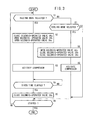
- step S1 it is determined whether the heating mode or the cooling mode of the vehicular air-conditioning system 10 is selected. If the heating mode is selected (YES in step S1), then control goes to step S2 in which the solenoid-operated valve 38a is closed and the solenoid-operated valves 38b, 38c are opened.
- step S3 the compressor 16 is activated in step S3.
- the compressor 16 now delivers the coolant into the heat pump circulation passage 18.
- the coolant is supplied to the heater 26 which performs a heat exchange between the coolant and the air-conditioning air, i.e., radiates the heat from the coolant to the air-conditioning air, thereby increasing the temperature of the air-conditioning air.
- the coolant discharged from the heater 26 flows through the first bypass passage 40a into the gas-liquid separator 34 in bypassing relation to the condenser 20.
- the coolant is cooled while it flows through the gas-liquid separator 34 and the auxiliary condenser 36, and then is sent to the expansion valve 22.
- the coolant is depressurized by the expansion valve 22 and flows through the three-way valve 46a into the branch passage 28, from which the coolant is introduced into the second evaporator 30.
- the second evaporator 30 performs a heat exchange between the coolant and the heat from the cabin 14.
- the coolant then flows from the second evaporator 30 and through the second bypass passage 40b and the expansion valve 22 in bypassing relation to the first evaporator 24, and is then delivered again to the compressor 16.
- the coolant retrieval passage 44 extends from the divider 42 between the condenser 20 and the gas-liquid separator 34 and is connected to the compressor 16, and the solenoid-operated valve 38c connected to the coolant retrieval passage 44 is open at this time.
- the compressor 16 When the compressor 16 is actuated while in the heating mode, a pressure difference is developed in the coolant retrieval passage 44. Specifically, in the coolant retrieval passage 44, the pressure at the compressor 16 is lower than the pressure at the divider 42. Therefore, the coolant in the form of a liquid which remains in the condenser 20 is forcibly drawn, i.e., retrieved, toward the compressor 16 through the coolant retrieval passage 44 due to the pressure difference in the coolant retrieval passage 44. Accordingly, the coolant in the form of a liquid which remains in the condenser 20 is easily and quickly retrieved, and the condenser 20 is prevented from dropping in performance.
- the heater 26 is connected downstream directly to the gas-liquid separator 34 in bypassing relation to the condenser 20. Therefore, the gas-liquid separator 34 functions as an auxiliary cooling tank, and the auxiliary condenser 36 functions as an auxiliary cooling unit.
- the coolant is thus introduced as a fully liquid medium into the expansion valve 22, with any gas being prevented from being trapped therein.
- the coolant is thus stably circulated in the heat pump circulation passage 18 for higher heat exchange efficiency.
- the gas-liquid separator 34 functions as an auxiliary cooling tank, a sufficient amount of coolant is maintained in the vehicular air-conditioning system 10. Consequently, the vehicular air-conditioning system 10 is prevented from dropping in air-conditioning performance due to a shortage of coolant while the vehicular air-conditioning system 10 is operating in a transient period.
- the vehicular air-conditioning system 10 it is possible for the vehicular air-conditioning system 10 to circulate the coolant stably with a simple and economical arrangement and to operate with increased heat exchange efficiency for better air-conditioning capability.
- step S4 If the compressor 16 has been actuated for a given time (prescribed time) (YES in step S4), then control goes to step S5 in which the solenoid-operated valve 38c is closed. Thus, the coolant stops being retrieved from the condenser 20, and the vehicular air-conditioning system 10 enters a normal heating mode. If it is judged that the heating mode is stopped (YES in step S6), then the vehicular air-conditioning system 10 is shut down.
- step S7 determines whether the cooling mode of the vehicular air-conditioning system 10 is selected or not. If it is judged that the cooling mode is not selected (NO in step S7), then control jumps to step S6. If it is judged that the cooling mode is selected (YES in step S7), then control goes to step S8.
- step S8 the solenoid-operated valve 38a is opened and the solenoid-operated valves 38b, 38c are closed. Then, control goes to step S9 in which the compressor 16 is activated.
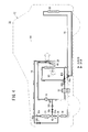
- the vehicular air-conditioning system 10 now starts to operate in the cooling mode, as shown in FIG. 4 .
- the solenoid-operated valve 38a is opened to connect the condenser 20 to the heat pump circulation passage 18.
- the three-way valves 46a, 46b are switched to disconnect the branch passage 28 from the heat pump circulation passage 18 and connect the first evaporator 24 to the heat pump circulation passage 18.
- the air-mixing damper 48 is brought into a fully closed position, i.e., a position to cover the heater 26.
- the coolant which has been compressed and heated to a higher temperature by the compressor 16 flows through the heater 26 and is cooled by the condenser 20, the gas-liquid separator 34, and the auxiliary condenser 36.
- the coolant becomes lower in temperature and pressure in the expansion valve 22, and then is supplied to the first evaporator 24.
- the first evaporator 24 performs a heat exchange between the coolant which is lower in temperature and pressure and the air-conditioning air, thereby cooling the air-conditioning air. After having absorbed the heat from the air-conditioning air, the coolant is returned from the expansion valve 22 to the compressor 16.
- the air-conditioning air cooled by the first evaporator 24 is not heated by the heater 26, and is introduced into the cabin 14, cooling the cabin 14.
- the gas-liquid separator 34 provides a damping action on the coolant as it increases or decreases in volume.
- FIG. 5 is a diagram, partly in block form, of a vehicular air-conditioning system 60 according to a second embodiment of the present invention. Those parts of the vehicular air-conditioning system 60 which are identical to those of the vehicular air-conditioning system 10 according to the first embodiment are denoted by identical reference characters, and will not be described in detail below.
- the vehicular air-conditioning system 60 is mounted on an automobile (vehicle) 62 (see FIG. 6 ).
- the heat pump circulation passage 18 includes a condenser unit 64 as an auxiliary cooling condenser, which provides an auxiliary cooling cycle.
- the condenser unit 64 is disposed downstream of the heater 26 and is connected in series thereto.
- the condenser unit 64 comprises a main condenser (condensing unit) 20a, a gas-liquid separating coolant storage (auxiliary cooling tank) 34a, and an auxiliary condenser (supercooling unit) 36a, through which the coolant flows in the cooling mode.
- the heat pump circulation passage 18 includes a coolant retrieval passage 44a extending from a divider 42a at an end of the main condenser 20a and connected to the compressor 16.
- the second backflow check valve 32b and the solenoid-operated valve 38c are connected to the coolant retrieval passage 44a.
- the vehicular air-conditioning system 60 operates in the heating mode and the cooling mode according to the flowchart shown in FIG. 3 , as with the vehicular air-conditioning system 10 according to the first embodiment.
- the vehicular air-conditioning system 60 When the vehicular air-conditioning system 60 operates in the heating mode, as shown in FIG. 6 , the solenoid-operated valve 38a is closed and the solenoid-operated valves 38b, 38c are opened. In the heating mode, the coolant in the form of a liquid which remains in the condenser 20 is forcibly drawn toward the compressor 16 due to the pressure difference in the coolant retrieval passage 44a. Consequently, the vehicular air-conditioning system 60 according to the second embodiment offers the same advantages as the vehicular air-conditioning system 10 according to the first embodiment, e.g., it allows the coolant in the form of a liquid to be well and reliably retrieved.
- the vehicular air-conditioning system 60 When the vehicular air-conditioning system 60 operates in the cooling mode, as shown in FIG. 7 , the solenoid-operated valve 38a is opened and the solenoid-operated valves 38b, 38c are closed. Therefore, the vehicular air-conditioning system 60 according to the second embodiment offers the same advantages as the vehicular air-conditioning system 10 according to the first embodiment.
- the heating medium supplied to the second evaporator 30 for a heat exchange may be any medium which is higher in temperature than the coolant that flows into the second evaporator 30, e.g., a medium heated by motors, a medium heated by batteries, a medium heated by an internal combustion engine if the automobile 12 or 62 is powered by such an internal combustion engine, a medium heated by the controller 52, a medium carrying ambient heat, or the like, in addition to the waste heat gas from the cabin 14.
- Each of the three-way valves 46a, 46b may comprise an integral structure including a three-way dividing mechanism and a valve mechanism or a combination of a dividing block and a solenoid-operated valve.
- a vehicular air-conditioning system (10) has a heat pump circulation passage (18) for circulating a coolant with a compressor (16).
- a condenser (20) for performing a heat exchange between a coolant and ambient air, an expansion valve (22), a first evaporator (24), a heater (26), and a second evaporator (30).
- the heat pump circulation passage (18) includes a coolant retrieval passage (44) extending from a divider (42) between the condenser (20) and the gas-liquid separator (34) and connected to the compressor (16).
- a second backflow check valve (32b) for preventing the coolant from flowing from the compressor (16) to the divider (42) and a solenoid-operated valve (38c) are connected to the coolant retrieval passage (44).
Landscapes
- Engineering & Computer Science (AREA)
- Physics & Mathematics (AREA)
- Thermal Sciences (AREA)
- Mechanical Engineering (AREA)
- Chemical & Material Sciences (AREA)
- Combustion & Propulsion (AREA)
- Air-Conditioning For Vehicles (AREA)
Abstract
Description
- The present invention relates to a heat-pump vehicular air-conditioning system for use on a vehicle for air-conditioning the passenger's cabin of the vehicle. Description of the Related Art:
- Various vehicular air-conditioning systems have been used for use on various vehicles including engine vehicle powered by an internal combustion engine, hybrid vehicles powered by an engine and a secondary battery (or a secondary battery and a fuel cell), electric vehicles, and fuel cell vehicles, etc.
- One of such vehicular air-conditioning systems is a heat-pump air-conditioning system. For example, as shown in
FIG. 8 of the accompanying drawings, a cooling and heating system for use on automobiles as disclosed in Japanese Patent No.3929606 compressor 1, anexterior condenser 2, aliquid tank 3, anexpansion valve 4, and aninterior evaporator 5 which are connected successively in the order named bycoolant pipes 6. - The cooling and heating system also includes a bypass pipe 7 for guiding a coolant discharged from the
compressor 1 directly into theliquid tank 3 in bypassing relation to theexterior condenser 2. A first solenoid-operatedvalve 8a is connected to thecoolant pipe 6 that is connected to the inlet of theexterior condenser 2. Aninterior condenser 2a and a second solenoid-operatedvalve 8b are connected to the bypass pipe 7. - When the cooling and heating system operates in a cooling mode, the first solenoid-operated
valve 8a is opened and the second solenoid-operatedvalve 8b is closed to deliver the coolant discharged from thecompressor 1 into theexterior condenser 2. When the cooling and heating system operates in a heating mode, the first solenoid-operatedvalve 8a is closed and the second solenoid-operatedvalve 8b is opened to send the coolant discharged from thecompressor 1 into the bypass pipe 7. - The outlet of the
exterior condenser 2 is directly connected to the inlet of thecompressor 1 by acoolant retrieval pipe 9 which is connected to a third solenoid-operatedvalve 8c. When the heating mode is selected, the first solenoid-operatedvalve 8a, the second solenoid-operatedvalve 8b, and the third solenoid-operatedvalve 8c are controlled to retrieve the coolant which has remained in theexterior condenser 2 into a heating cycle. - According to Japanese Patent No.
3929606 exterior condenser 2 and theliquid tank 3 which serves as a receiver tank is employed. Therefore, cavitation (evaporation of the liquid coolant) occurs in the liquid line, tending to cause an insufficient coolant flow rate with respect to the opening of theexpansion valve 4. - The receiver cycle suffers from a relatively low cooling capability. If the cooling capability is to be increased, then the amount of coolant used and the weight of the cooling and heating system are increased, making the cooling and heating system less suitable for use on vehicles. Furthermore, the
compressor 1 needs an increase in its ability, which is detrimental to the fuel economy of the vehicle that incorporates the cooling and heating system. - It is an object of the present invention to provide a vehicular air-conditioning system which is of a simple and economical structure, allows a coolant to circulate stably, has an increased heat exchange efficiency, and is capable of maintaining a good air-conditioning capability.
- According to the present invention, there is provided an air-conditioning system for use on a vehicle, comprising a heat pump circulation passage for circulating a coolant with a compressor, a condenser disposed in the heat pump circulation passage, for performing a heat exchange between the coolant and ambient air, an expansion valve disposed in the heat pump circulation passage, for depressurizing the coolant which is delivered from the condenser, a first evaporator disposed in the heat pump circulation passage, for performing a heat exchange between the coolant which has passed through the expansion valve and air-conditioning air, a heater disposed in the heat pump circulation passage, for performing a heat exchange between the coolant which is delivered from the compressor and the air-conditioning air which has passed through the first evaporator, and a second evaporator disposed in a branch passage branched from the heat pump circulation passage, for performing a heat exchange between the coolant and a heating medium obtained from within or outside the vehicle.
- The air-conditioning system also includes a gas-liquid separator and an auxiliary condenser which are disposed downstream of the condenser and connected between the condenser and the expansion valve, and the heat pump circulation passage includes a coolant retrieval passage extending from a divider between the condenser and the gas-liquid separator and connected to the compressor.
- According to the present invention, the coolant that remains in the condenser is retrieved to the compressor due to a pressure difference which is developed in the coolant retrieval passage connected between the condenser and the gas-liquid separator. Therefore, the coolant that remains in the condenser is retrieved easily and quickly for effectively preventing from dropping in performance.
- The auxiliary condenser is disposed downstream of the gas-liquid separator with the divider being disposed upstream thereof. The auxiliary condenser functions as an auxiliary cooling unit when the air-conditioning system operates in a cooling mode and a heating mode. There is no need for an auxiliary cooling unit to be used exclusively in the heating mode, for example.
- Accordingly, it is possible for the air-conditioning system to circulate the coolant stably with a simple and economical arrangement and to operate with increased heat exchange efficiency for better air-conditioning capability.
- The above and other objects, features, and advantages of the present invention will become more apparent from the following description when taken in conjunction with the accompanying drawings in which preferred embodiments of the present invention are shown by way of illustrative example.
-
-
FIG. 1 is a diagram, partly in block form, of a vehicular air-conditioning system according to a first embodiment of the present invention; -
FIG. 2 is a diagram of the vehicular air-conditioning system shown inFIG. 1 which operates in a heating mode; -
FIG. 3 is a flowchart of an operation sequence of the vehicular air-conditioning system shown inFIG. 1 ; -
FIG. 4 is a diagram of the vehicular air-conditioning system shown inFIG. 1 which operates in a cooling mode; -
FIG. 5 is a diagram, partly in block form, of a vehicular air-conditioning system according to a second embodiment of the present invention; -
FIG. 6 is a diagram of the vehicular air-conditioning system shown inFIG. 5 which operates in a heating mode; -
FIG. 7 is a diagram of the vehicular air-conditioning system shown inFIG. 5 which operates in a cooling mode; and -
FIG. 8 is a diagram, partly in block form, of a cooling and heating system for use on automobiles as disclosed in Japanese Patent No.3929606 - As shown in
FIGS. 1 and2 , a vehicular air-conditioning system 10 according to a first embodiment of the present invention is mounted on an automobile (vehicle) 12 for air-conditioning a passenger's cabin (passenger compartment) 14 of theautomobile 12. - The vehicular air-
conditioning system 10 includes a heatpump circulation passage 18 through which a coolant is circulated by acompressor 16. To the heatpump circulation passage 18, there are connected acondenser 20 for performing a heat exchange between the coolant and the ambient air, anexpansion valve 22 for depressurizing the coolant sent from thecondenser 20, afirst evaporator 24 for performing a heat exchange between the coolant that has passed through theexpansion valve 22 and air-conditioning air, and aheater 26 for performing a heat exchange between the coolant which has been delivered from thecompressor 16 and the air-conditioning air that has passed through thefirst evaporator 24. - A
branch passage 28 is branched from the heatpump circulation passage 18 and connected to asecond evaporator 30 for performing a heat exchange between the coolant and a heating medium obtained from within or outside theautomobile 12, e.g., a heating medium discharged from thecabin 14 out of the automobile 12 (a waste heat gas from the cabin 14). - Since the heating medium supplied to the
second evaporator 30 for a heat exchange is a waste heat gas from thecabin 14, the heat produced in thecabin 14 is not wasted but effectively utilized. When the vehicular air-conditioning system 10 starts to operate in a heating mode, the heat that is supplied to warm thecabin 14 is retrieved and introduced back into the vehicular air-conditioning system 10. Consequently, the vehicular air-conditioning system 10 can quickly start to operate. - A first backflow check valve (backflow check means) 32a, a gas-
liquid separator 34, and an auxiliary condenser (auxiliary cooling condenser) 36 are successively disposed downstream of thecondenser 20 and connected between thecondenser 20 and theexpansion valve 22. The firstbackflow check valve 32a serves to prevent the coolant from flowing from the gas-liquid separator 34 to thecondenser 20. A solenoid-operated valve (on-off valve) 38a is disposed upstream of thecondenser 20. The heatpump circulation passage 18 includes afirst bypass passage 40a connected to the gas-liquid separator 34 in bypassing relation to thecondenser 20. A solenoid-operated valve (on-off valve) 38b is connected to thefirst bypass passage 40a. - The heat
pump circulation passage 18 also includes acoolant retrieval passage 44 extending from adivider 42 between thecondenser 20 and the gas-liquid separator 34 and connected to thecompressor 16. To thecoolant retrieval passage 44, there are connected a second backflow check valve (backflow check means) 32b for preventing the coolant from flowing from thecompressor 16 to thedivider 42, and a solenoid-operated valve (on-off valve) 38c. - The
expansion valve 22 has a means (not shown) for detecting the temperature of the coolant which is delivered from thefirst evaporator 24 that cools the air-conditioning air. Theexpansion valve 22 automatically changes its opening to change the flow rate of the coolant depending on the detected temperature of the coolant delivered from thefirst evaporator 24. - The heat
pump circulation passage 18 has a three-way valve 46a connected at the junction between a portion of the heatpump circulation passage 18 which is positioned near and connected to theexpansion valve 22 and an inlet end of thebranch passage 28, and a three-way valve 46b connected at the junction between an outlet end of asecond bypass passage 40b which bypasses thefirst evaporator 24 and the heatpump circulation passage 18. Thesecond evaporator 30 is disposed in a rear portion of the automobile 12 (seeFIG. 2 ). - An air-
mixing damper 48 for delivering the air-conditioning air which has been cooled by thefirst evaporator 24 into thecabin 14 without flowing through theheater 26 is disposed between thefirst evaporator 24 and theheater 26. - The
automobile 12 has anambient air inlet 50 for introducing ambient air as air-conditioning air into thecabin 14. Thefirst evaporator 24 and theheater 26 are disposed successively in the order named downstream of theambient air inlet 50. The vehicular air-conditioning system 10 also includes a controller (ECU) 52 (seeFIG. 1 ) for controlling overall operation of the vehicular air-conditioning system 10. Thecontroller 52 also functions as a flow passage switching means for controlling the solenoid-operatedvalves way valves conditioning system 10. - Operation of the vehicular air-
conditioning system 10 will be described below with reference to a flowchart shown inFIG. 3 . - First, it is determined whether the heating mode or the cooling mode of the vehicular air-
conditioning system 10 is selected in step S1. If the heating mode is selected (YES in step S1), then control goes to step S2 in which the solenoid-operatedvalve 38a is closed and the solenoid-operatedvalves - Then, the
compressor 16 is activated in step S3. Thecompressor 16 now delivers the coolant into the heatpump circulation passage 18. The coolant is supplied to theheater 26 which performs a heat exchange between the coolant and the air-conditioning air, i.e., radiates the heat from the coolant to the air-conditioning air, thereby increasing the temperature of the air-conditioning air. - As the solenoid-operated
valve 38a is closed and the solenoid-operatedvalve 38b is open, the coolant discharged from theheater 26 flows through thefirst bypass passage 40a into the gas-liquid separator 34 in bypassing relation to thecondenser 20. The coolant is cooled while it flows through the gas-liquid separator 34 and theauxiliary condenser 36, and then is sent to theexpansion valve 22. - The coolant is depressurized by the
expansion valve 22 and flows through the three-way valve 46a into thebranch passage 28, from which the coolant is introduced into thesecond evaporator 30. Thesecond evaporator 30 performs a heat exchange between the coolant and the heat from thecabin 14. The coolant then flows from thesecond evaporator 30 and through thesecond bypass passage 40b and theexpansion valve 22 in bypassing relation to thefirst evaporator 24, and is then delivered again to thecompressor 16. - According to the first embodiment, the
coolant retrieval passage 44 extends from thedivider 42 between thecondenser 20 and the gas-liquid separator 34 and is connected to thecompressor 16, and the solenoid-operatedvalve 38c connected to thecoolant retrieval passage 44 is open at this time. - When the
compressor 16 is actuated while in the heating mode, a pressure difference is developed in thecoolant retrieval passage 44. Specifically, in thecoolant retrieval passage 44, the pressure at thecompressor 16 is lower than the pressure at thedivider 42. Therefore, the coolant in the form of a liquid which remains in thecondenser 20 is forcibly drawn, i.e., retrieved, toward thecompressor 16 through thecoolant retrieval passage 44 due to the pressure difference in thecoolant retrieval passage 44. Accordingly, the coolant in the form of a liquid which remains in thecondenser 20 is easily and quickly retrieved, and thecondenser 20 is prevented from dropping in performance. - In the heating mode, the
heater 26 is connected downstream directly to the gas-liquid separator 34 in bypassing relation to thecondenser 20. Therefore, the gas-liquid separator 34 functions as an auxiliary cooling tank, and theauxiliary condenser 36 functions as an auxiliary cooling unit. - The coolant is thus introduced as a fully liquid medium into the
expansion valve 22, with any gas being prevented from being trapped therein. The coolant is thus stably circulated in the heatpump circulation passage 18 for higher heat exchange efficiency. - Since the gas-
liquid separator 34 functions as an auxiliary cooling tank, a sufficient amount of coolant is maintained in the vehicular air-conditioning system 10. Consequently, the vehicular air-conditioning system 10 is prevented from dropping in air-conditioning performance due to a shortage of coolant while the vehicular air-conditioning system 10 is operating in a transient period. - In the first embodiment, there is no need for an auxiliary cooling tank and an auxiliary cooling unit to be used exclusively in the heating mode because the gas-
liquid separator 34 and theauxiliary condenser 36 can be used also in the cooling mode. Accordingly, it is possible for the vehicular air-conditioning system 10 to circulate the coolant stably with a simple and economical arrangement and to operate with increased heat exchange efficiency for better air-conditioning capability. - If the
compressor 16 has been actuated for a given time (prescribed time) (YES in step S4), then control goes to step S5 in which the solenoid-operatedvalve 38c is closed. Thus, the coolant stops being retrieved from thecondenser 20, and the vehicular air-conditioning system 10 enters a normal heating mode. If it is judged that the heating mode is stopped (YES in step S6), then the vehicular air-conditioning system 10 is shut down. - If the heating mode is not selected (NO in step S1), then control goes to step S7 which determines whether the cooling mode of the vehicular air-
conditioning system 10 is selected or not. If it is judged that the cooling mode is not selected (NO in step S7), then control jumps to step S6. If it is judged that the cooling mode is selected (YES in step S7), then control goes to step S8. - In step S8, the solenoid-operated
valve 38a is opened and the solenoid-operatedvalves compressor 16 is activated. The vehicular air-conditioning system 10 now starts to operate in the cooling mode, as shown inFIG. 4 . - In the cooling mode, the solenoid-operated
valve 38a is opened to connect thecondenser 20 to the heatpump circulation passage 18. The three-way valves branch passage 28 from the heatpump circulation passage 18 and connect thefirst evaporator 24 to the heatpump circulation passage 18. The air-mixingdamper 48 is brought into a fully closed position, i.e., a position to cover theheater 26. - The coolant which has been compressed and heated to a higher temperature by the
compressor 16 flows through theheater 26 and is cooled by thecondenser 20, the gas-liquid separator 34, and theauxiliary condenser 36. The coolant becomes lower in temperature and pressure in theexpansion valve 22, and then is supplied to thefirst evaporator 24. Thefirst evaporator 24 performs a heat exchange between the coolant which is lower in temperature and pressure and the air-conditioning air, thereby cooling the air-conditioning air. After having absorbed the heat from the air-conditioning air, the coolant is returned from theexpansion valve 22 to thecompressor 16. - Inasmuch as the air-mixing
damper 48 is closed, the air-conditioning air cooled by thefirst evaporator 24 is not heated by theheater 26, and is introduced into thecabin 14, cooling thecabin 14. In the cooling mode, the gas-liquid separator 34 provides a damping action on the coolant as it increases or decreases in volume. -
FIG. 5 is a diagram, partly in block form, of a vehicular air-conditioning system 60 according to a second embodiment of the present invention. Those parts of the vehicular air-conditioning system 60 which are identical to those of the vehicular air-conditioning system 10 according to the first embodiment are denoted by identical reference characters, and will not be described in detail below. - The vehicular air-
conditioning system 60 is mounted on an automobile (vehicle) 62 (seeFIG. 6 ). As shown inFIGS. 5 and6 , the heatpump circulation passage 18 includes acondenser unit 64 as an auxiliary cooling condenser, which provides an auxiliary cooling cycle. Thecondenser unit 64 is disposed downstream of theheater 26 and is connected in series thereto. Thecondenser unit 64 comprises a main condenser (condensing unit) 20a, a gas-liquid separating coolant storage (auxiliary cooling tank) 34a, and an auxiliary condenser (supercooling unit) 36a, through which the coolant flows in the cooling mode. - The heat
pump circulation passage 18 includes acoolant retrieval passage 44a extending from adivider 42a at an end of themain condenser 20a and connected to thecompressor 16. The secondbackflow check valve 32b and the solenoid-operatedvalve 38c are connected to thecoolant retrieval passage 44a. - According to the second embodiment, the vehicular air-
conditioning system 60 operates in the heating mode and the cooling mode according to the flowchart shown inFIG. 3 , as with the vehicular air-conditioning system 10 according to the first embodiment. - When the vehicular air-
conditioning system 60 operates in the heating mode, as shown inFIG. 6 , the solenoid-operatedvalve 38a is closed and the solenoid-operatedvalves condenser 20 is forcibly drawn toward thecompressor 16 due to the pressure difference in thecoolant retrieval passage 44a. Consequently, the vehicular air-conditioning system 60 according to the second embodiment offers the same advantages as the vehicular air-conditioning system 10 according to the first embodiment, e.g., it allows the coolant in the form of a liquid to be well and reliably retrieved. - When the vehicular air-
conditioning system 60 operates in the cooling mode, as shown inFIG. 7 , the solenoid-operatedvalve 38a is opened and the solenoid-operatedvalves conditioning system 60 according to the second embodiment offers the same advantages as the vehicular air-conditioning system 10 according to the first embodiment. - In each of the first and second embodiments, the heating medium supplied to the
second evaporator 30 for a heat exchange may be any medium which is higher in temperature than the coolant that flows into thesecond evaporator 30, e.g., a medium heated by motors, a medium heated by batteries, a medium heated by an internal combustion engine if theautomobile controller 52, a medium carrying ambient heat, or the like, in addition to the waste heat gas from thecabin 14. - Each of the three-
way valves - A vehicular air-conditioning system (10) has a heat pump circulation passage (18) for circulating a coolant with a compressor (16). To the heat pump circulation passage (18), there are connected a condenser (20) for performing a heat exchange between a coolant and ambient air, an expansion valve (22), a first evaporator (24), a heater (26), and a second evaporator (30). The heat pump circulation passage (18) includes a coolant retrieval passage (44) extending from a divider (42) between the condenser (20) and the gas-liquid separator (34) and connected to the compressor (16). A second backflow check valve (32b) for preventing the coolant from flowing from the compressor (16) to the divider (42) and a solenoid-operated valve (38c) are connected to the coolant retrieval passage (44).
Claims (7)
- An air-conditioning system for use on a vehicle, comprising:a heat pump circulation passage (18) for circulating a coolant with a compressor (16);a condenser (20) disposed in the heat pump circulation passage (18), for performing a heat exchange between the coolant and ambient air;an expansion valve (22) disposed in the heat pump circulation passage (18), for depressurizing the coolant which is delivered from the condenser (20);a first evaporator (24) disposed in the heat pump circulation passage (18), for performing a heat exchange between the coolant which has passed through the expansion valve (22) and air-conditioning air;a heater (26) disposed in the heat pump circulation passage (18), for performing a heat exchange between the coolant which is delivered from the compressor (16) and the air-conditioning air which has passed through the first evaporator (24);a second evaporator (30) disposed in a branch passage (28) branched from the heat pump circulation passage (18), for performing a heat exchange between the coolant and a heating medium obtained from within or outside the vehicle; anda gas-liquid separator (34) and an auxiliary condenser (36) which are disposed downstream of the condenser (20) and connected between the condenser (20) and the expansion valve (22) ;wherein the heat pump circulation passage (18) includes a coolant retrieval passage (44) extending from a divider (42) between the condenser (20) and the gas-liquid separator (34) and connected to the compressor (16).
- The air-conditioning system according to claim 1, further comprising backflow check means (32b) connected to the coolant retrieval passage (44), for preventing the coolant from flowing from the compressor (16) to the divider (42).
- The air-conditioning system according to claim 1, further comprising an on-off valve (38c) connected to the coolant retrieval passage (44);
wherein the on-off valve (38c) is opened in a heating mode and closed in a cooling mode. - The air-conditioning system according to claim 2, further comprising an on-off valve (38c) connected to the coolant retrieval passage (44);
wherein the on-off valve (38c) is opened in a heating mode and closed in a cooling mode. - The air-conditioning system according to claim 3, further comprising a controller (52) for switching between the heating mode and the cooling mode and controlling opening and closing of the on-off valve (38c);
wherein in the heating mode, the controller (52) opens the on-off valve (38c) and thereafter activates the compressor (16) for a prescribed time and then closes the on-off valve (38c). - The air-conditioning system according to claim 4, further comprising a controller (52) for switching between the heating mode and the cooling mode and controlling opening and closing of the on-off valve (38c);
wherein in the heating mode, the controller (52) opens the on-off valve (38c) and thereafter activates the compressor (16) for a prescribed time and then closes the on-off valve (38c). - The air-conditioning system according to claim 1, wherein the heating medium which is supplied to the second evaporator (30) for a heat exchange with the coolant comprises a medium which is higher in temperature than the coolant.
Applications Claiming Priority (1)
| Application Number | Priority Date | Filing Date | Title |
|---|---|---|---|
| JP2010005117A JP5021773B2 (en) | 2010-01-13 | 2010-01-13 | Vehicle air conditioning system |
Publications (2)
| Publication Number | Publication Date |
|---|---|
| EP2345550A1 true EP2345550A1 (en) | 2011-07-20 |
| EP2345550B1 EP2345550B1 (en) | 2013-03-20 |
Family
ID=43511192
Family Applications (1)
| Application Number | Title | Priority Date | Filing Date |
|---|---|---|---|
| EP11150674A Not-in-force EP2345550B1 (en) | 2010-01-13 | 2011-01-12 | Vehicular air-conditioning system |
Country Status (3)
| Country | Link |
|---|---|
| US (1) | US20110167849A1 (en) |
| EP (1) | EP2345550B1 (en) |
| JP (1) | JP5021773B2 (en) |
Cited By (2)
| Publication number | Priority date | Publication date | Assignee | Title |
|---|---|---|---|---|
| EP2774787A1 (en) * | 2013-03-04 | 2014-09-10 | Volkswagen Aktiengesellschaft | Air-conditioning system for a vehicle and method for air-conditioning a vehicle |
| CN105650780A (en) * | 2014-11-12 | 2016-06-08 | 海马轿车有限公司 | Automobile electric heat pump air conditioner system |
Families Citing this family (15)
| Publication number | Priority date | Publication date | Assignee | Title |
|---|---|---|---|---|
| KR101241222B1 (en) * | 2011-07-21 | 2013-03-13 | 기아자동차주식회사 | Heat pump system control method for vehicle |
| JP4597180B2 (en) * | 2007-11-06 | 2010-12-15 | 本田技研工業株式会社 | Vehicle air conditioning system |
| US9902235B2 (en) | 2011-09-06 | 2018-02-27 | Valeo Japan Co., Ltd. | Vehicle air-conditioning apparatus |
| US9435551B2 (en) * | 2011-09-15 | 2016-09-06 | Khanh Dinh | Dehumidifier dryer using ambient heat enhancement |
| JP5944154B2 (en) * | 2011-12-09 | 2016-07-05 | サンデンホールディングス株式会社 | Air conditioner for vehicles |
| US9027358B2 (en) | 2012-02-27 | 2015-05-12 | Nissan North America, Inc. | Vehicle heat pump system |
| US9855821B2 (en) * | 2012-08-20 | 2018-01-02 | Hanon Systems | Heat pump system for vehicle |
| DE102012108886B4 (en) | 2012-09-20 | 2019-02-14 | Hanon Systems | Heat exchanger arrangement and air conditioning system of a motor vehicle |
| JP6011375B2 (en) * | 2013-02-01 | 2016-10-19 | 株式会社デンソー | Refrigeration cycle equipment |
| US20150027143A1 (en) * | 2013-07-26 | 2015-01-29 | GM Global Technology Operations LLC | Cabin exhaust air heat recovery system including a heat pump system having a non-freezing evaporator |
| US9499026B2 (en) * | 2013-09-16 | 2016-11-22 | Denso International America, Inc. | Vehicular air-conditioning system with a switching heat exchanger |
| CN104515335B (en) * | 2013-10-08 | 2017-09-26 | 翰昂汽车零部件有限公司 | Vehicle heat pump |
| CN111433549A (en) | 2017-07-17 | 2020-07-17 | 分形散热器技术有限责任公司 | Multi-fractal heat sink system and method |
| US12023983B2 (en) * | 2021-03-24 | 2024-07-02 | Ford Global Technologies, Llc | Methods and systems for instant cabin heat for a vehicle |
| DE102021003157A1 (en) | 2021-06-18 | 2022-12-22 | Mercedes-Benz Group AG | Air conditioning system for a motor vehicle, method for operating an air conditioning system and motor vehicle |
Citations (6)
| Publication number | Priority date | Publication date | Assignee | Title |
|---|---|---|---|---|
| JPH09109669A (en) * | 1995-10-17 | 1997-04-28 | Calsonic Corp | Air conditioner for electric vehicle |
| EP0888912A2 (en) * | 1997-06-30 | 1999-01-07 | Calsonic Corporation | Automotive air conditioning system |
| EP0913281A1 (en) * | 1997-10-30 | 1999-05-06 | Calsonic Corporation | Vehicular air conditioning apparatus |
| EP0913282A1 (en) * | 1996-09-06 | 1999-05-06 | Calsonic Corporation | Heat pump type air conditioning system for automotive vehicle |
| US6230505B1 (en) * | 1996-11-15 | 2001-05-15 | Calsonic Kansei Corporation | Heat pump type air conditioning system for automotive vehicle |
| JP3929606B2 (en) | 1998-07-08 | 2007-06-13 | カルソニックカンセイ株式会社 | Air conditioner for automobile |
Family Cites Families (8)
| Publication number | Priority date | Publication date | Assignee | Title |
|---|---|---|---|---|
| JP3980186B2 (en) * | 1997-10-23 | 2007-09-26 | カルソニックカンセイ株式会社 | Heat pump type automotive air conditioner |
| JP3436872B2 (en) * | 1997-11-07 | 2003-08-18 | 株式会社テージーケー | Automotive air conditioners |
| JP2000094952A (en) * | 1998-09-24 | 2000-04-04 | Zexel Corp | Air conditioning system for vehicle |
| JP2005263013A (en) * | 2004-03-18 | 2005-09-29 | Denso Corp | Vehicular air-conditioner |
| JP2009051475A (en) * | 2007-08-29 | 2009-03-12 | Denso Corp | Air conditioner for vehicles |
| JP4597180B2 (en) * | 2007-11-06 | 2010-12-15 | 本田技研工業株式会社 | Vehicle air conditioning system |
| EP2524830B1 (en) * | 2010-01-12 | 2014-04-30 | Honda Motor Co., Ltd. | Air conditioning system for vehicle |
| JPWO2011118483A1 (en) * | 2010-03-23 | 2013-07-04 | 本田技研工業株式会社 | Operation method of heat pump type vehicle air conditioning system |
-
2010
- 2010-01-13 JP JP2010005117A patent/JP5021773B2/en not_active Expired - Fee Related
-
2011
- 2011-01-12 US US13/005,130 patent/US20110167849A1/en not_active Abandoned
- 2011-01-12 EP EP11150674A patent/EP2345550B1/en not_active Not-in-force
Patent Citations (6)
| Publication number | Priority date | Publication date | Assignee | Title |
|---|---|---|---|---|
| JPH09109669A (en) * | 1995-10-17 | 1997-04-28 | Calsonic Corp | Air conditioner for electric vehicle |
| EP0913282A1 (en) * | 1996-09-06 | 1999-05-06 | Calsonic Corporation | Heat pump type air conditioning system for automotive vehicle |
| US6230505B1 (en) * | 1996-11-15 | 2001-05-15 | Calsonic Kansei Corporation | Heat pump type air conditioning system for automotive vehicle |
| EP0888912A2 (en) * | 1997-06-30 | 1999-01-07 | Calsonic Corporation | Automotive air conditioning system |
| EP0913281A1 (en) * | 1997-10-30 | 1999-05-06 | Calsonic Corporation | Vehicular air conditioning apparatus |
| JP3929606B2 (en) | 1998-07-08 | 2007-06-13 | カルソニックカンセイ株式会社 | Air conditioner for automobile |
Cited By (3)
| Publication number | Priority date | Publication date | Assignee | Title |
|---|---|---|---|---|
| EP2774787A1 (en) * | 2013-03-04 | 2014-09-10 | Volkswagen Aktiengesellschaft | Air-conditioning system for a vehicle and method for air-conditioning a vehicle |
| CN105650780A (en) * | 2014-11-12 | 2016-06-08 | 海马轿车有限公司 | Automobile electric heat pump air conditioner system |
| CN105650780B (en) * | 2014-11-12 | 2018-07-13 | 海马汽车有限公司 | A kind of motorcar electric heat pump air conditioning system |
Also Published As
| Publication number | Publication date |
|---|---|
| US20110167849A1 (en) | 2011-07-14 |
| JP2011143796A (en) | 2011-07-28 |
| JP5021773B2 (en) | 2012-09-12 |
| EP2345550B1 (en) | 2013-03-20 |
Similar Documents
| Publication | Publication Date | Title |
|---|---|---|
| EP2345550B1 (en) | Vehicular air-conditioning system | |
| EP2524830A1 (en) | Air conditioning system for vehicle | |
| US12017510B2 (en) | Method for controlling heating of vehicle thermal management system | |
| EP2551135B1 (en) | Operation method of heat pump-type vehicle air conditioning system | |
| US20090314023A1 (en) | Heating, Ventilating and/or Air Conditioning System With Cold Air Storage | |
| US5735133A (en) | Vehicular cooling system with thermal storage | |
| US7975757B2 (en) | Vehicle HVAC and RESS thermal management | |
| US7228705B2 (en) | Air-conditioning installation, especially for motor vehicles | |
| KR102474341B1 (en) | Heat pump system for a vehicle | |
| EP2301777A1 (en) | Method for controlling the passenger compartment temperature of an electrically operated vehicle and air-conditioning system | |
| US20150273976A1 (en) | Vehicle heat management system | |
| US20150060559A1 (en) | Method and system for transmitting heat for a vehicle | |
| US12285996B2 (en) | Method for controlling vehicle thermal management system | |
| CN110293817B (en) | Electric vehicle heat pump air conditioning system and defrosting method thereof | |
| US20220274463A1 (en) | Method for controlling pressure in vehicle thermal management system | |
| CN221090418U (en) | Indirect heat pump thermal management system and vehicle | |
| JP2006015965A (en) | Vehicular air-conditioner | |
| KR20220036260A (en) | Vehicle thermal management system | |
| JP3481138B2 (en) | Refrigeration cycle with bypass line | |
| CN112895843B (en) | Thermal management system for a motor vehicle and motor vehicle having such a thermal management system | |
| US12275292B2 (en) | Thermal management system for vehicle | |
| US20170036513A1 (en) | Air conditioning device for vehicle | |
| US7607313B2 (en) | Vehicle HVAC system | |
| KR20170085160A (en) | Battery heating device for vehicle and air conditioner for vehicle therewith | |
| US20250187402A1 (en) | Vehicle hvac system and method for controlling the same |
Legal Events
| Date | Code | Title | Description |
|---|---|---|---|
| PUAI | Public reference made under article 153(3) epc to a published international application that has entered the european phase |
Free format text: ORIGINAL CODE: 0009012 |
|
| 17P | Request for examination filed |
Effective date: 20110112 |
|
| AK | Designated contracting states |
Kind code of ref document: A1 Designated state(s): AL AT BE BG CH CY CZ DE DK EE ES FI FR GB GR HR HU IE IS IT LI LT LU LV MC MK MT NL NO PL PT RO RS SE SI SK SM TR |
|
| AX | Request for extension of the european patent |
Extension state: BA ME |
|
| 17Q | First examination report despatched |
Effective date: 20120301 |
|
| GRAP | Despatch of communication of intention to grant a patent |
Free format text: ORIGINAL CODE: EPIDOSNIGR1 |
|
| GRAS | Grant fee paid |
Free format text: ORIGINAL CODE: EPIDOSNIGR3 |
|
| GRAA | (expected) grant |
Free format text: ORIGINAL CODE: 0009210 |
|
| AK | Designated contracting states |
Kind code of ref document: B1 Designated state(s): AL AT BE BG CH CY CZ DE DK EE ES FI FR GB GR HR HU IE IS IT LI LT LU LV MC MK MT NL NO PL PT RO RS SE SI SK SM TR |
|
| REG | Reference to a national code |
Ref country code: GB Ref legal event code: FG4D |
|
| REG | Reference to a national code |
Ref country code: CH Ref legal event code: EP |
|
| REG | Reference to a national code |
Ref country code: IE Ref legal event code: FG4D |
|
| REG | Reference to a national code |
Ref country code: AT Ref legal event code: REF Ref document number: 601842 Country of ref document: AT Kind code of ref document: T Effective date: 20130415 |
|
| REG | Reference to a national code |
Ref country code: DE Ref legal event code: R096 Ref document number: 602011001078 Country of ref document: DE Effective date: 20130508 |
|
| PG25 | Lapsed in a contracting state [announced via postgrant information from national office to epo] |
Ref country code: NO Free format text: LAPSE BECAUSE OF FAILURE TO SUBMIT A TRANSLATION OF THE DESCRIPTION OR TO PAY THE FEE WITHIN THE PRESCRIBED TIME-LIMIT Effective date: 20130620 Ref country code: ES Free format text: LAPSE BECAUSE OF FAILURE TO SUBMIT A TRANSLATION OF THE DESCRIPTION OR TO PAY THE FEE WITHIN THE PRESCRIBED TIME-LIMIT Effective date: 20130701 Ref country code: SE Free format text: LAPSE BECAUSE OF FAILURE TO SUBMIT A TRANSLATION OF THE DESCRIPTION OR TO PAY THE FEE WITHIN THE PRESCRIBED TIME-LIMIT Effective date: 20130320 Ref country code: LT Free format text: LAPSE BECAUSE OF FAILURE TO SUBMIT A TRANSLATION OF THE DESCRIPTION OR TO PAY THE FEE WITHIN THE PRESCRIBED TIME-LIMIT Effective date: 20130320 Ref country code: BG Free format text: LAPSE BECAUSE OF FAILURE TO SUBMIT A TRANSLATION OF THE DESCRIPTION OR TO PAY THE FEE WITHIN THE PRESCRIBED TIME-LIMIT Effective date: 20130620 |
|
| REG | Reference to a national code |
Ref country code: AT Ref legal event code: MK05 Ref document number: 601842 Country of ref document: AT Kind code of ref document: T Effective date: 20130320 |
|
| REG | Reference to a national code |
Ref country code: LT Ref legal event code: MG4D |
|
| PG25 | Lapsed in a contracting state [announced via postgrant information from national office to epo] |
Ref country code: LV Free format text: LAPSE BECAUSE OF FAILURE TO SUBMIT A TRANSLATION OF THE DESCRIPTION OR TO PAY THE FEE WITHIN THE PRESCRIBED TIME-LIMIT Effective date: 20130320 Ref country code: SI Free format text: LAPSE BECAUSE OF FAILURE TO SUBMIT A TRANSLATION OF THE DESCRIPTION OR TO PAY THE FEE WITHIN THE PRESCRIBED TIME-LIMIT Effective date: 20130320 Ref country code: FI Free format text: LAPSE BECAUSE OF FAILURE TO SUBMIT A TRANSLATION OF THE DESCRIPTION OR TO PAY THE FEE WITHIN THE PRESCRIBED TIME-LIMIT Effective date: 20130320 Ref country code: GR Free format text: LAPSE BECAUSE OF FAILURE TO SUBMIT A TRANSLATION OF THE DESCRIPTION OR TO PAY THE FEE WITHIN THE PRESCRIBED TIME-LIMIT Effective date: 20130621 |
|
| REG | Reference to a national code |
Ref country code: NL Ref legal event code: VDEP Effective date: 20130320 |
|
| PG25 | Lapsed in a contracting state [announced via postgrant information from national office to epo] |
Ref country code: RS Free format text: LAPSE BECAUSE OF FAILURE TO SUBMIT A TRANSLATION OF THE DESCRIPTION OR TO PAY THE FEE WITHIN THE PRESCRIBED TIME-LIMIT Effective date: 20130320 Ref country code: BE Free format text: LAPSE BECAUSE OF FAILURE TO SUBMIT A TRANSLATION OF THE DESCRIPTION OR TO PAY THE FEE WITHIN THE PRESCRIBED TIME-LIMIT Effective date: 20130320 Ref country code: HR Free format text: LAPSE BECAUSE OF FAILURE TO SUBMIT A TRANSLATION OF THE DESCRIPTION OR TO PAY THE FEE WITHIN THE PRESCRIBED TIME-LIMIT Effective date: 20130320 |
|
| PG25 | Lapsed in a contracting state [announced via postgrant information from national office to epo] |
Ref country code: PT Free format text: LAPSE BECAUSE OF FAILURE TO SUBMIT A TRANSLATION OF THE DESCRIPTION OR TO PAY THE FEE WITHIN THE PRESCRIBED TIME-LIMIT Effective date: 20130722 Ref country code: AT Free format text: LAPSE BECAUSE OF FAILURE TO SUBMIT A TRANSLATION OF THE DESCRIPTION OR TO PAY THE FEE WITHIN THE PRESCRIBED TIME-LIMIT Effective date: 20130320 Ref country code: NL Free format text: LAPSE BECAUSE OF FAILURE TO SUBMIT A TRANSLATION OF THE DESCRIPTION OR TO PAY THE FEE WITHIN THE PRESCRIBED TIME-LIMIT Effective date: 20130320 Ref country code: EE Free format text: LAPSE BECAUSE OF FAILURE TO SUBMIT A TRANSLATION OF THE DESCRIPTION OR TO PAY THE FEE WITHIN THE PRESCRIBED TIME-LIMIT Effective date: 20130320 Ref country code: CZ Free format text: LAPSE BECAUSE OF FAILURE TO SUBMIT A TRANSLATION OF THE DESCRIPTION OR TO PAY THE FEE WITHIN THE PRESCRIBED TIME-LIMIT Effective date: 20130320 Ref country code: IS Free format text: LAPSE BECAUSE OF FAILURE TO SUBMIT A TRANSLATION OF THE DESCRIPTION OR TO PAY THE FEE WITHIN THE PRESCRIBED TIME-LIMIT Effective date: 20130720 Ref country code: SK Free format text: LAPSE BECAUSE OF FAILURE TO SUBMIT A TRANSLATION OF THE DESCRIPTION OR TO PAY THE FEE WITHIN THE PRESCRIBED TIME-LIMIT Effective date: 20130320 Ref country code: RO Free format text: LAPSE BECAUSE OF FAILURE TO SUBMIT A TRANSLATION OF THE DESCRIPTION OR TO PAY THE FEE WITHIN THE PRESCRIBED TIME-LIMIT Effective date: 20130320 |
|
| PG25 | Lapsed in a contracting state [announced via postgrant information from national office to epo] |
Ref country code: PL Free format text: LAPSE BECAUSE OF FAILURE TO SUBMIT A TRANSLATION OF THE DESCRIPTION OR TO PAY THE FEE WITHIN THE PRESCRIBED TIME-LIMIT Effective date: 20130320 Ref country code: CY Free format text: LAPSE BECAUSE OF FAILURE TO SUBMIT A TRANSLATION OF THE DESCRIPTION OR TO PAY THE FEE WITHIN THE PRESCRIBED TIME-LIMIT Effective date: 20130320 |
|
| PLBE | No opposition filed within time limit |
Free format text: ORIGINAL CODE: 0009261 |
|
| STAA | Information on the status of an ep patent application or granted ep patent |
Free format text: STATUS: NO OPPOSITION FILED WITHIN TIME LIMIT |
|
| PG25 | Lapsed in a contracting state [announced via postgrant information from national office to epo] |
Ref country code: DK Free format text: LAPSE BECAUSE OF FAILURE TO SUBMIT A TRANSLATION OF THE DESCRIPTION OR TO PAY THE FEE WITHIN THE PRESCRIBED TIME-LIMIT Effective date: 20130320 |
|
| 26N | No opposition filed |
Effective date: 20140102 |
|
| PG25 | Lapsed in a contracting state [announced via postgrant information from national office to epo] |
Ref country code: IT Free format text: LAPSE BECAUSE OF FAILURE TO SUBMIT A TRANSLATION OF THE DESCRIPTION OR TO PAY THE FEE WITHIN THE PRESCRIBED TIME-LIMIT Effective date: 20130320 |
|
| REG | Reference to a national code |
Ref country code: DE Ref legal event code: R097 Ref document number: 602011001078 Country of ref document: DE Effective date: 20140102 |
|
| PG25 | Lapsed in a contracting state [announced via postgrant information from national office to epo] |
Ref country code: LU Free format text: LAPSE BECAUSE OF FAILURE TO SUBMIT A TRANSLATION OF THE DESCRIPTION OR TO PAY THE FEE WITHIN THE PRESCRIBED TIME-LIMIT Effective date: 20140112 |
|
| PGFP | Annual fee paid to national office [announced via postgrant information from national office to epo] |
Ref country code: DE Payment date: 20131213 Year of fee payment: 4 |
|
| REG | Reference to a national code |
Ref country code: CH Ref legal event code: PL |
|
| PG25 | Lapsed in a contracting state [announced via postgrant information from national office to epo] |
Ref country code: LI Free format text: LAPSE BECAUSE OF NON-PAYMENT OF DUE FEES Effective date: 20140131 Ref country code: CH Free format text: LAPSE BECAUSE OF NON-PAYMENT OF DUE FEES Effective date: 20140131 |
|
| REG | Reference to a national code |
Ref country code: FR Ref legal event code: ST Effective date: 20140930 |
|
| REG | Reference to a national code |
Ref country code: IE Ref legal event code: MM4A |
|
| PG25 | Lapsed in a contracting state [announced via postgrant information from national office to epo] |
Ref country code: FR Free format text: LAPSE BECAUSE OF NON-PAYMENT OF DUE FEES Effective date: 20140131 |
|
| PG25 | Lapsed in a contracting state [announced via postgrant information from national office to epo] |
Ref country code: IE Free format text: LAPSE BECAUSE OF NON-PAYMENT OF DUE FEES Effective date: 20140112 |
|
| PG25 | Lapsed in a contracting state [announced via postgrant information from national office to epo] |
Ref country code: MC Free format text: LAPSE BECAUSE OF FAILURE TO SUBMIT A TRANSLATION OF THE DESCRIPTION OR TO PAY THE FEE WITHIN THE PRESCRIBED TIME-LIMIT Effective date: 20130320 |
|
| REG | Reference to a national code |
Ref country code: DE Ref legal event code: R119 Ref document number: 602011001078 Country of ref document: DE |
|
| GBPC | Gb: european patent ceased through non-payment of renewal fee |
Effective date: 20150112 |
|
| PG25 | Lapsed in a contracting state [announced via postgrant information from national office to epo] |
Ref country code: GB Free format text: LAPSE BECAUSE OF NON-PAYMENT OF DUE FEES Effective date: 20150112 Ref country code: DE Free format text: LAPSE BECAUSE OF NON-PAYMENT OF DUE FEES Effective date: 20150801 |
|
| PG25 | Lapsed in a contracting state [announced via postgrant information from national office to epo] |
Ref country code: MT Free format text: LAPSE BECAUSE OF FAILURE TO SUBMIT A TRANSLATION OF THE DESCRIPTION OR TO PAY THE FEE WITHIN THE PRESCRIBED TIME-LIMIT Effective date: 20130320 |
|
| PG25 | Lapsed in a contracting state [announced via postgrant information from national office to epo] |
Ref country code: SM Free format text: LAPSE BECAUSE OF FAILURE TO SUBMIT A TRANSLATION OF THE DESCRIPTION OR TO PAY THE FEE WITHIN THE PRESCRIBED TIME-LIMIT Effective date: 20130320 |
|
| PG25 | Lapsed in a contracting state [announced via postgrant information from national office to epo] |
Ref country code: TR Free format text: LAPSE BECAUSE OF FAILURE TO SUBMIT A TRANSLATION OF THE DESCRIPTION OR TO PAY THE FEE WITHIN THE PRESCRIBED TIME-LIMIT Effective date: 20130320 Ref country code: HU Free format text: LAPSE BECAUSE OF FAILURE TO SUBMIT A TRANSLATION OF THE DESCRIPTION OR TO PAY THE FEE WITHIN THE PRESCRIBED TIME-LIMIT; INVALID AB INITIO Effective date: 20110112 |
|
| PG25 | Lapsed in a contracting state [announced via postgrant information from national office to epo] |
Ref country code: MK Free format text: LAPSE BECAUSE OF FAILURE TO SUBMIT A TRANSLATION OF THE DESCRIPTION OR TO PAY THE FEE WITHIN THE PRESCRIBED TIME-LIMIT Effective date: 20130320 |
|
| PG25 | Lapsed in a contracting state [announced via postgrant information from national office to epo] |
Ref country code: AL Free format text: LAPSE BECAUSE OF FAILURE TO SUBMIT A TRANSLATION OF THE DESCRIPTION OR TO PAY THE FEE WITHIN THE PRESCRIBED TIME-LIMIT Effective date: 20130320 |