EP2345452A1 - Vorrichtung für medizinische Anwendungen - Google Patents
Vorrichtung für medizinische Anwendungen Download PDFInfo
- Publication number
- EP2345452A1 EP2345452A1 EP11150326A EP11150326A EP2345452A1 EP 2345452 A1 EP2345452 A1 EP 2345452A1 EP 11150326 A EP11150326 A EP 11150326A EP 11150326 A EP11150326 A EP 11150326A EP 2345452 A1 EP2345452 A1 EP 2345452A1
- Authority
- EP
- European Patent Office
- Prior art keywords
- electrode
- distal end
- resistance
- temperature
- resistance element
- Prior art date
- Legal status (The legal status is an assumption and is not a legal conclusion. Google has not performed a legal analysis and makes no representation as to the accuracy of the status listed.)
- Withdrawn
Links
- 230000005672 electromagnetic field Effects 0.000 claims abstract description 13
- 239000007943 implant Substances 0.000 claims abstract description 8
- 238000010521 absorption reaction Methods 0.000 claims abstract description 3
- 230000036760 body temperature Effects 0.000 claims description 8
- 230000008859 change Effects 0.000 claims description 6
- 230000000638 stimulation Effects 0.000 claims description 6
- 230000004936 stimulating effect Effects 0.000 claims description 4
- 238000002679 ablation Methods 0.000 claims description 3
- 238000005259 measurement Methods 0.000 claims description 3
- 230000035939 shock Effects 0.000 claims description 3
- 230000001419 dependent effect Effects 0.000 description 5
- 238000010586 diagram Methods 0.000 description 4
- 238000010438 heat treatment Methods 0.000 description 3
- 239000004020 conductor Substances 0.000 description 2
- 230000008878 coupling Effects 0.000 description 2
- 238000010168 coupling process Methods 0.000 description 2
- 238000005859 coupling reaction Methods 0.000 description 2
- 238000013507 mapping Methods 0.000 description 2
- 206010037660 Pyrexia Diseases 0.000 description 1
- 230000009471 action Effects 0.000 description 1
- JRPBQTZRNDNNOP-UHFFFAOYSA-N barium titanate Chemical compound [Ba+2].[Ba+2].[O-][Ti]([O-])([O-])[O-] JRPBQTZRNDNNOP-UHFFFAOYSA-N 0.000 description 1
- 229910002113 barium titanate Inorganic materials 0.000 description 1
- 230000000747 cardiac effect Effects 0.000 description 1
- 238000013194 cardioversion Methods 0.000 description 1
- 239000011248 coating agent Substances 0.000 description 1
- 238000000576 coating method Methods 0.000 description 1
- 238000004891 communication Methods 0.000 description 1
- 230000006378 damage Effects 0.000 description 1
- 230000007423 decrease Effects 0.000 description 1
- 230000005669 field effect Effects 0.000 description 1
- 238000002347 injection Methods 0.000 description 1
- 239000007924 injection Substances 0.000 description 1
- 238000003780 insertion Methods 0.000 description 1
- 230000037431 insertion Effects 0.000 description 1
- WABPQHHGFIMREM-VENIDDJXSA-N lead-201 Chemical compound [201Pb] WABPQHHGFIMREM-VENIDDJXSA-N 0.000 description 1
- 239000000463 material Substances 0.000 description 1
- 238000012986 modification Methods 0.000 description 1
- 230000004048 modification Effects 0.000 description 1
- 238000013021 overheating Methods 0.000 description 1
- 230000009467 reduction Effects 0.000 description 1
- 230000035945 sensitivity Effects 0.000 description 1
- 230000000451 tissue damage Effects 0.000 description 1
- 231100000827 tissue damage Toxicity 0.000 description 1
Images



Classifications
-
- A—HUMAN NECESSITIES
- A61—MEDICAL OR VETERINARY SCIENCE; HYGIENE
- A61N—ELECTROTHERAPY; MAGNETOTHERAPY; RADIATION THERAPY; ULTRASOUND THERAPY
- A61N1/00—Electrotherapy; Circuits therefor
- A61N1/02—Details
- A61N1/04—Electrodes
- A61N1/05—Electrodes for implantation or insertion into the body, e.g. heart electrode
-
- A—HUMAN NECESSITIES
- A61—MEDICAL OR VETERINARY SCIENCE; HYGIENE
- A61N—ELECTROTHERAPY; MAGNETOTHERAPY; RADIATION THERAPY; ULTRASOUND THERAPY
- A61N1/00—Electrotherapy; Circuits therefor
- A61N1/02—Details
- A61N1/08—Arrangements or circuits for monitoring, protecting, controlling or indicating
- A61N1/086—Magnetic resonance imaging [MRI] compatible leads
-
- G—PHYSICS
- G01—MEASURING; TESTING
- G01R—MEASURING ELECTRIC VARIABLES; MEASURING MAGNETIC VARIABLES
- G01R33/00—Arrangements or instruments for measuring magnetic variables
- G01R33/20—Arrangements or instruments for measuring magnetic variables involving magnetic resonance
- G01R33/28—Details of apparatus provided for in groups G01R33/44 - G01R33/64
- G01R33/288—Provisions within MR facilities for enhancing safety during MR, e.g. reduction of the specific absorption rate [SAR], detection of ferromagnetic objects in the scanner room
Definitions
- the present invention relates to a medical device comprising an elongated conductive member having a distal end.
- an elongated conductive element may, for. B. be a line.
- a defibrillator 102 is in electrical communication with a lead 103, which here carries a special electrode in the form of a shock electrode 104, which is located at its distal end and is placed in the heart of the patient.
- the defibrillation is usually monopolar over a current path between this electrode 104 and a counter electrode 105, which is more or less remote from the heart H to be stimulated.
- the housing of the defibrillator 102 which includes the units for detecting cardiac signals and generating electrical pulses, may act as a counter electrode 105.
- the tip 202 of the lead includes two electrodes 203 and 204 for performing a so-called bipolar cardioversion. While the electrode 203 makes contact at the tip of the lead 201, the electrode 204 is shown as Ring contact configured on the circumference of the line.
- the lead comprises two spirally wound conductors 205 and 206 which respectively electrically connect the electrodes 203 and 204 to a connector plug (not shown) at the proximal end of the lead.
- Fig. 1 Patients undergoing a conventional defibrillation regimen Fig. 1 can not currently be examined with the help of a magnetic resonance tomograph (MRI), As a result of the strong electromagnetic alternating fields, a strong heating of the lead tip and a related damage to the surrounding tissue can occur.
- MRI magnetic resonance tomograph
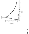
- Fig. 3 a typical temperature profile of a lead tip of a defibrillation device in a magnetic resonance tomograph is shown.
- the temperature of the lead tip rises rapidly, the steepness of the rise and the maximum temperature occurring being highly dependent on the conduction position with respect to the electromagnetic field of the magnetic resonance tomograph. If the electromagnetic alternating field is switched off (designated by 302), the line tip cools down relatively quickly due to its comparatively low heat capacity.
- a medical device comprising an elongate conductive member having a distal end, in which a resistance element is disposed in the vicinity of the distal end that exhibits its resistance as a function of temperature and / or electromagnetic energy field changed.
- the resistance element is configured to reduce a temperature rise of the distal end caused by energy absorption from an electromagnetic field.
- the resistance element may be a temperature-dependent resistor whose operating points z. B. between 38 ° C and 45 ° C.
- the resistance element may be a magnetic field-dependent resistor, such as. B. a GMR (Giant Magneto Resistance) element.
- a circuit may be formed, which represents a variable resistor.
- the resistive element is not more than 20mm from a tip of the elongate conductive element.
- the resistance element can be arranged so that there is a good thermal conductivity between the tip and the resistance element, in particular the resistance element can connect directly to the tip.
- the resistive element is disposed between the tip and a lead.
- the resistive element is a PTC thermistor configured to be low-resistance at body temperature and to become high-ohmic at a temperature that is above body temperature but below a tissue-damaging temperature.
- the distal end is connected via the PTC thermistor high impedance to the proximal end of the elongated conductive element, so that the temperature rise of the distal end decreases significantly.
- the PTC thermistor is designed to be low resistance at 37 ° C and high resistance at 44 ° C.
- the PTC thermistor may be at least partially encompassed by the distal end.
- the distal end may be coated.
- the resistance element is in the form of a cylinder having a concentric bore, the cylinder at least partially forming or embracing the elongate conductive element.
- the elongated conductive member may include a lead-out unit disposed proximate the distal end that directs energy received from an electromagnetic field away from the distal end. By dissipating the energy, a further reduction of the temperature maximum at the distal end can be achieved.
- the dissipation unit includes a thermistor configured to be high impedance at body temperature and to become low impedance at a temperature that is above body temperature but below a tissue damaging temperature.
- the thermistor is formed to be high impedance at 37 ° C and low impedance at 44 ° C, but different values are possible.
- the distal end comprises an electrode pole.
- the elongated conductive element may comprise at least one further electrode pole.
- the device according to the invention can be configured to optimally distribute energy from the elongated conductive element to the electrode poles.
- the device according to the invention is designed as an electrode line.
- the device may comprise an electrode spaced from the distal end, in particular a ring electrode or a shock coil of a multipolar electrode, to which in particular the discharge unit dissipates the absorbed energy.
- the distal end may be a heart stimulating electrode, an implantable cardioverter defibrillator (ICD), a transvenous ICD electrode, a subcutaneously implantable ICD electrode, or an neurostimulation electrode.
- ICD implantable cardioverter defibrillator
- an MRI-safe electrode line can be provided in a simple and inexpensive way.
- the line remains flexible.
- the device according to the invention can be designed as a catheter, in particular as an ablation, balloon or insertion catheter, as a guide wire, as an introducer sheath or as a stent.
- the invention comprises an implant (an assembly) with a device according to the invention, wherein the distal end comprises an electrode for stimulating a body part and the electrode is driven based on a stimulation parameter.
- the implant comprises a device for detecting a change in the resistance of the resistance element and a device for adapting the stimulation parameter based on the detected change in the resistance of the resistance element.
- the implant may include an input stage having a sensor for receiving measurement signals describing the state of the body part to be stimulated and means for adjusting a characteristic of the input stage based on the detected change in resistance of the resistance element.
- z. B the stimulation performance of the defibrillator be adapted to the situation. Furthermore, z. For example, the sensitivity of a measurement unit that the defibrillator uses to control its pacing behavior can be adjusted.
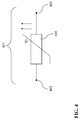
- Fig. 4 shows an equivalent circuit diagram of a device according to the invention 401, which is designed as an electrode line.
- An elongated conductive element 402 includes a distal end 403 and a PTC resistor 404.
- the PTC resistor 404 located near the distal end is heated.
- the PTC thermistor 404 becomes high-impedance, thus reducing the temperature rise.
- FIG. 4 illustrates an equivalent circuit diagram of another embodiment of a device 501 according to the invention.
- An elongate conductive element 502 includes a distal end 503 and a PTC thermistor 504. Further, the elongate conductive element 502 includes a NTC resistor 505. The thermistor 505 connects the elongate conductive member 502 to a ring electrode 506. As the temperature increases, the thermistor 505 becomes low-resistance, thus diverting the energy received from the electromagnetic field from the distal end 503 to the more thermally non-critical ring electrode 506.
- Fig. 6 illustrates a possible resistance curve of the in Fig. 4 and 5 PTC thermistors 404, 504 shown in the example given.
- the lowest resistance value of the PTC thermistor is 37 ° C.
- the resistance of the PTC thermistor increases and reaches a high-ohmic value below the limit of tissue damage, but well above the possible body core temperature including fever.
- thermistor 505 applies a correspondingly reversed characteristic.
- Fig. 7 shows an embodiment of a device according to the invention, which is designed as an electrode line 701.
- a distal end 703 of the elongated conductive member 702 is designed as a screw and connected via the elongated conductive member 702 with a connector, not shown.
- a cylindrical PTC thermistor 704 is mounted near the distal end 703, which is connected to the elongate conductive element 702.
- a thermistor 705 is located between the elongated conductive member 702 and a ring electrode 706.
- Fig. 8 describes a further embodiment of a device according to the invention, which is designed as an electrode line 801.
- An elongate conductive member 802, a thermistor 805, and a ring electrode 806 correspond to the elongated conductive member 702 and the ring electrode 706 Fig. 7 , Notwithstanding the embodiment of Fig. 7 exists in Fig. 8 a distal end 803 of a PTC thermistor material, such. B. a sintered body of barium titanate, so that can be dispensed with a separate PTC thermistor. In this case, the distal end 803 is coated with a coating 803a.
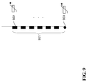
- Fig. 9 describes another embodiment of a device according to the invention, which is designed as a multipolar electrophysiological mapping catheter 901.
- Each of the ring electrodes 902 and the tip electrode 903 are made of or include a PTC thermistor. Because of the same electrode surfaces, each of the ring or tip electrodes has the same probability that it heats up in the critical region, so that none of the abovementioned electrode can be connected as a counter electrode to a thermistor.
- a balloon catheter comprises a so-called hypotube shaft which serves to stiffen the catheter, comprises a galvanically conductive material and extends from the proximal end to about 40 cm in front of the balloon.
- the hypotube shaft is designed as a device according to the invention in order to reduce heating in an MRI.
- ablation catheters and introducer sheaths which have electrodes at the distal end and are connected to the proximal end via an electrical lead can also be constructed like a device according to the invention.
Landscapes
- Health & Medical Sciences (AREA)
- Cardiology (AREA)
- Heart & Thoracic Surgery (AREA)
- Engineering & Computer Science (AREA)
- Biomedical Technology (AREA)
- Nuclear Medicine, Radiotherapy & Molecular Imaging (AREA)
- Radiology & Medical Imaging (AREA)
- Life Sciences & Earth Sciences (AREA)
- Animal Behavior & Ethology (AREA)
- General Health & Medical Sciences (AREA)
- Public Health (AREA)
- Veterinary Medicine (AREA)
- Electrotherapy Devices (AREA)
Abstract
Die vorliegende Erfindung betrifft eine Vorrichtung für medizinische Anwendungen. Die Vorrichtung umfasst ein längliches leitfähiges Element mit einem distalen Ende. In der Nähe des distalen Endes ist ein Widerstandselement angeordnet. Dieses verändert seinen Widerstand in Abhängigkeit einer Temperatur und/oder eines elektromagnetischen Feldes. Dabei ist das Widerstandselement dazu ausgebildet, einen durch Energieaufnahme aus einem elektromagnetischen Feld verursachten Temperaturanstieg des distalen Endes zu verringern.
Description
- Die vorliegende Erfindung betrifft eine Vorrichtung für medizinische Anwendungen, welche ein längliches leitfähiges Element mit einem distalen Ende umfasst. Ein solches längliches leitfähiges Element kann z. B. eine Leitung sein.
- Solche Vorrichtungen werden unter anderem in einer implantierbaren Defibrillationsanordnung 101 verwendet, wie Sie zum Beispiel aus der
US 5,531,766 bekannt und inFig. 1 illustriert ist. Um das Herz H des Patienten P zu stimulieren, steht ein Defibrillator 102 in elektrischer Verbindung mit einer Leitung 103, welche hier eine spezielle Elektrode in Form einer Schockelektrode 104 trägt, die sich an ihrem distalen Ende befindet und im Herzen des Patienten verlegt wird. Die Defibrillation erfolgt in der Regel monopolar über einen Strompfad zwischen dieser Elektrode 104 und einer Gegenelektrode 105, die mehr oder weniger entfernt von dem zu stimulierenden Herzen H liegt. Beispielsweise kann das Gehäuse des Defibrillators 102, das die Einheiten zur Detektion von Herzsignalen und Erzeugung von elektrischen Impulsen enthält, als Gegenelektrode 105 wirken. -
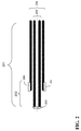
Fig. 2 zeigt in einer anderen möglichen Ausführungsform das distale Ende einer Leitung 201. Die Spitze 202 der Leitung umfasst zur Ausführung einer sogenannten bipolaren Kardioversion zwei Elektroden 203 und 204. Während die Elektrode 203 einen Kontakt an der Spitze der Leitung 201 bildet, ist die Elektrode 204 als Ringkontakt am Umfang der Leitung ausgestaltet. Die Zuleitung umfasst zwei spiralig gewickelte Leiter 205 und 206, die jeweils die Elektroden 203 und 204 elektrisch mit einem (nicht gezeigten) Anschlussstecker am proximalen Ende der Leitung verbinden. - Patienten, die eine konventionelle Defibrillationsanordnung nach
Fig. 1 in sich tragen, können derzeit nicht mit Hilfe eines Magnetresonanztomographen (MRT) untersucht werden, da es aufgrund der starken elektromagnetischen Wechselfelder zu einer starken Erwärmung der Leitungsspitze und einer damit zusammenhängenden Schädigung des umliegenden Gewebes kommen kann. - In
Fig. 3 ist ein typischer Temperaturverlauf einer Leitungsspitze einer Defibrillationsanordnung in einem Magnetresonanztomographen dargestellt. Mit dem Einschalten des elektromagnetischen Feldes (bezeichnet mit 301) steigt die Temperatur der Leitungsspitze rasch an, wobei die Steilhalt des Anstieges und die maximal auftretende Temperatur stark von der Leitungslage bezogen auf das elektromagnetische Feld des Magnetresonanztomographen abhängig sind. Wird das elektromagnetische Wechselfeld abgeschaltet (bezeichnet mit 302), kühlt sich die Leitungsspitze aufgrund ihrer vergleichsweise geringen Wärmekapazität verhältnismäßig schnell wieder ab. - Zur Lösung des beschriebenen Erhitzungsproblems schlägt die
US-Patentanmeldung 2009/0105789 A1 vor, einen temperaturabhängigen Schalter einzusetzen, der bei Erwärmung die Leitungsspitze von der Zuleitung trennt. Ein solcher Schalter führt jedoch zu ungünstigen konstruktiven Eigenschaften der Leitung, insbesondere zu einer Steifheit der Elektrode. Darüber hinaus besitzt der Thermoschalter eine deutliche Hysterese, der Temperaturbereich ist schlecht einstellbar, und die Leitungsspitze kann nur komplett zu- oder abgeschaltet werden, so dass im abgeschalteten Zustand weder eine Stimulation des Herzens noch eine Ableitung von Signalen möglich ist.
Das Überhitzungsproblem der Elektrodenflächen tritt auch bei der temporären Anwendung von Elektroden, elektrisch aktiven Kathetern und metallischen, teilweise isolierten Führungsdrähten im MRT auf. Daher wird die Anwendung des MRT, z.B. im Rahmen elektrophysiologischer Untersuchungen (Mapping) entsprechend eingeschränkt. - Gemäß einem Aspekt der Erfindung wird eine Vorrichtung für medizinische Anwendungen, die ein längliches leitfähiges Element mit einem distalen Ende umfasst, bereitgestellt, bei der in der Nähe des distalen Endes ein Widerstandselement angeordnet ist, das seinen Widerstand in Abhängigkeit einer Temperatur und/oder eines elektromagnetischen Feldes verändert. Das Widerstandselement ist dazu ausgebildet, einen durch Energieaufnahme aus einem elektromagnetischen Feld verursachten Temperaturanstieg des distalen Endes zu verringern.
- Dabei kann das Widerstandselement ein temperaturabhängiger Widerstand sein, dessen Arbeitspunkte z. B. zwischen 38°C und 45°C liegen. Weiterhin kann das Widerstandselement ein magnetfeldabhängiger Widerstand sein, wie z. B. ein GMR (Giant MagnetoResistance)-Element. Auch mittels eines Feldeffekttransistors kann eine Schaltung gebildet sein, die einen veränderlichen Widerstand darstellt.
- In einer Ausführungsform ist das Widerstandselement nicht mehr als 20mm von einer Spitze des länglichen leitfähigen Elements entfernt. Das Widerstandselement kann so angeordnet sein, dass eine gute Wärmeleitfähigkeit zwischen der Spitze und dem Widerstandselement besteht, insbesondere kann sich das Widerstandselement unmittelbar an die Spitze anschließen. In einer Ausführungsform ist das Widerstandselement zwischen der Spitze und einer Zuleitung angeordnet.
- In einer Ausführungsform ist das Widerstandselement ein Kaltleiter, der so ausgebildet ist, dass er bei Körpertemperatur niederohmig ist und bei einer Temperatur, die oberhalb der Körpertemperatur, aber unterhalb einer gewebeschädigenden Temperatur liegt, hochohmig wird. Während der Einkopplung eines elektromagnetischen Feldes durch den Magnetresonanztomographen wird das distale Ende über den Kaltleiter hochohmig mit dem proximalen Ende des länglichen leitfähigen Elements verbunden, so dass der Temperaturanstieg des distalen Endes nennenswert abnimmt. In einer Ausführungsform ist der Kaltleiter so ausgebildet, dass er bei 37°C niederohmig und bei 44°C hochohmig ist.
- Der Kaltleiter kann zumindest teilweise vom distalen Ende umfasst sein. Dabei kann das distale Ende beschichtet sein.
- In einer Ausführungsform hat das Widerstandselement die Form eines Zylinders mit einer konzentrischen Bohrung, wobei der Zylinder das längliche leitfähige Element zumindest teilweise bildet oder es umgreift.
- Das längliche leitfähige Element kann eine Ableitungseinheit aufweisen, die in der Nähe des distalen Endes angeordnet ist und die aus einem elektromagnetischen Feld aufgenommene Energie von dem distalen Ende wegleitet. Durch das Ableiten der Energie kann eine weitere Reduktion des Temperaturmaximums am distalen Ende erreicht werden.
- In einer Ausführungsform umfasst die Ableitungseinheit einen Heißleiter, der so ausgebildet ist, dass er bei Körpertemperatur hochohmig ist und bei einer Temperatur, die oberhalb der Körpertemperatur, aber unterhalb einer gewebeschädigenden Temperatur liegt, niederohmig wird. In einer Ausführungsform ist der Heißleiter so ausgebildet, dass er bei 37°C hochohmig und bei 44°C niederohmig ist, abweichende Werte sind jedoch möglich.
- In einer Ausführungsform umfasst das distale Ende einen Elektrodenpol. Dabei kann das längliche leitfähige Element mindestens einen weiteren Elektrodenpol umfassen. Bei dieser Konstellation kann die erfindungsgemäße Vorrichtung dafür eingerichtet sein, Energie aus dem länglichen leitfähigen Element auf die Elektrodenpole möglichst optimal zu verteilen.
- In einer Ausführungsform ist die erfindungsgemäße Vorrichtung als Elektrodenleitung ausgebildet. Dabei kann die Vorrichtung eine vom distalen Ende beabstandete Elektrode, insbesondere eine Ringelektrode oder eine Schockwendel einer multipolaren Elektrode, umfassen, auf die insbesondere die Ableitungseinheit die aufgenommene Energie ableitet. Das distale Ende kann eine Elektrode zur Stimulation eines Herzens, eine ICD-Elektrode (ICD = Implantierbarer Kardioverter/Defibrillator), eine transvenöse ICD-Elektrode, eine subkutan implantierbare ICD-Elektrode oder eine Elektrode zur Neurostimulation sein.
- Mit Hilfe der erfindungsgemäßen Vorrichtung kann z. B. eine MRT-sichere Elektrodenleitung in einfacher und preiswerter Weise zur Verfügung gestellt werden. Die Leitung bleibt dabei flexibel. Darüber hinaus ist es möglich, bei Verwendung der erfindungsgemäßen Vorrichtung in einem Defibrillator in einem MRT-Umfeld weiterhin effektiv zu stimulieren, so dass auch schrittmacherabhängige Patienten während einer Untersuchung in einem MRT versorgt werden können.
- Die erfindungsgemäße Vorrichtung kann als Katheter, insbesondere als Ablations-, Ballon- oder Einführkatheter, als Führungsdraht, als Einführschleuse oder als Stent ausgebildet sein.
- Weiterhin umfasst die Erfindung ein Implantat (eine Anordnung) mit einer erfindungsgemäßen Vorrichtung, wobei das distale Ende eine Elektrode zur Stimulation eines Körperteils umfasst und die Elektrode basierend auf einem Stimulationsparameter angesteuert wird. Dabei umfasst das Implantat eine Einrichtung zur Erkennung einer Veränderung des Widerstands des Widerstandselements und eine Einrichtung zur Anpassung des Stimulationsparameters basierend auf der erkannten Veränderung des Widerstands des Widerstandselements. Das Implantat kann insbesondere eine Eingangsstufe mit einem Sensor zum Empfangen von Messsignalen, die den Zustand des zu stimulierenden Körperteils beschreiben, und einer Einrichtung zur Anpassung einer Charakteristik der Eingangsstufe basierend auf der erkannten Veränderung des Widerstands des Widerstandselements umfassen.
- Somit kann, wenn sich ein Patient mit Defibrillator in einem Magnetresonanztomographen befindet, z. B. die Stimulationsleistung des Defibrillators an die Situation angepasst werden. Weiterhin kann z. B. die Sensibilität einer Messeinheit, die der Defibrillator verwendet, um sein Stimulationsverhalten zu steuern, angepasst werden.
- Weitere Details der Erfindung und entsprechende Ausführungsformen werden im Folgenden anhand der Figuren beschrieben.
- Fig. 1
- zeigt einen Grundaufbau einer implantierbaren Defibrillationsanordnung.
- Fig. 2
- zeigt eine Ausführungsform eines distalen Endes einer Leitung.
- Fig. 3
- illustriert einen Temperaturverlauf einer Spitze einer Leitung während der Einkoppelung eines elektromagnetischen Feldes durch einen Magnetresonanztomographen.
- Fig. 4
- zeigt ein Ersatzschaltbild einer Ausführungsform einer erfindungsgemäßen Vorrichtung.
- Fig. 5
- zeigt ein Ersatzschaltbild einer weiteren Ausführungsform einer erfindungsgemäßen Vorrichtung.
- Fig. 6
- zeigt ein Beispiel eines Widerstandsverlaufes eines Kaltleiters.
- Fig. 7
- zeigt eine Ausführungsform einer erfindungsgemäßen Vorrichtung.
- Fig. 8
- zeigt eine weitere Ausführungsform einer erfindungsgemäßen Vorrichtung.
- Fig. 9
- zeigt eine weitere Ausführungsform einer erfindungsgemäßen Vorrichtung.
-
Fig. 4 zeigt ein Ersatzschaltbild einer erfindungsgemäßen Vorrichtung 401, die als Elektrodenleitung ausgebildet ist. Ein längliches leitfähiges Element 402 umfasst ein distales Ende 403 und einen Kaltleiter bzw. PTC-Widerstand 404. Wenn sich das distale Ende 403 während der Einkopplung eines elektromagnetischen Wechselfeldes durch einen MRT erhitzt, wird der in der Nähe des distalen Endes befindliche Kaltleiter 404 erwärmt. Dadurch wird der Kaltleiter 404 hochohmig und reduziert so den Temperaturanstieg. -
Fig. 5 stellt ein Ersatzschaltbild einer weiteren Ausführungsform einer erfindungsgemäßen Vorrichtung 501 dar. Ein längliches leitfähiges Element 502 umfasst ein distales Ende 503 und einen Kaltleiter 504. Weiterhin weist das längliche leitfähige Element 502 einen Heißleiter bzw. NTC-Widerstand 505 auf. Der Heißleiter 505 verbindet das längliche leitfähige Element 502 mit einer Ringelektrode 506. Mit steigender Temperatur wird der Heißleiter 505 niederohmig und leitet so die aus dem elektromagnetischen Feld aufgenommene Energie von dem distalen Ende 503 auf die thermisch unkritischere Ringelektrode 506 ab. -
Fig. 6 illustriert einen möglichen Widerstandsverlauf der inFig. 4 und5 gezeigten Kaltleiter 404, 504. In dem angegebenen Beispiel liegt der geringste Widerstandswert des Kaltleiters bei 37°C. Mit zunehmender Temperatur steigt der Widerstand des Kaltleiters an und erreicht einen hochohmigen Wert unterhalb der Grenze einer Gewebeschädigung, aber deutlich oberhalb der möglichen Körperkerntemperatur inklusive Fieber. Für den inFig. 5 gezeigten Heißleiter 505 gilt eine entsprechend umgekehrte Kennlinie. -
Fig. 7 zeigt eine Ausführungsform einer erfindungsgemäßen Vorrichtung, die als Elektrodenleitung 701 ausgebildet ist. Ein distales Ende 703 des länglichen leitfähigen Elements 702 ist als Schraube ausgeführt und über das längliche leitfähige Element 702 mit einem nicht gezeigten Anschlussstecker verbunden. Erfindungsgemäß ist in der Nähe des distalen Endes 703 ein zylindrischer Kaltleiter 704 montiert, der mit dem länglichen leitfähigen Element 702 verbunden ist. Ein Heißleiter 705 befindet sich zwischen dem länglichen leitfähigen Element 702 und einer Ringelektrode 706. -
Fig. 8 beschreibt eine weitere Ausführungsform einer erfindungsgemäßen Vorrichtung, die als Elektrodenleitung 801 ausgebildet ist. Ein längliches leitfähiges Element 802, ein Heißleiter 805 und eine Ringelektrode 806 entsprechen dem länglichen leitfähigen Element 702 und der Ringelektrode 706 ausFig. 7 . Abweichend zu der Ausführungsform ausFig. 7 besteht inFig. 8 ein distales Ende 803 aus einem Kaltleitermaterial, wie z. B. einem Sinterkörper aus Bariumtitanat, so dass auf einen gesonderten Kaltleiter verzichtet werden kann. Dabei ist das distale Ende 803 mit einer Beschichtung 803a überzogen. -
Fig. 9 beschreibt eine weitere Ausführungsform einer erfindungsgemäßen Vorrichtung, die als multipolarer elektrophysiologischer Mappingkatheter 901 ausgebildet ist. Jeder der Ringelektroden 902 und die Tip-Elektrode 903 sind aus einem Kaltleitermaterial gefertigt oder beinhalten einen solchen. Aufgrund der gleichen Elektrodenflächen besteht bei jeder der Ring- bzw. Tip-Elektroden die gleiche Wahrscheinlichkeit, dass diese sich im kritische Bereich erwärmt, so dass eine keine der genannten Elektrode als Gegenelektrode mit einem Heißleiter verschaltet werden kann. - In einer weiteren Ausführungsform der Erfindung umfasst ein Ballonkatheter einen sogenannten Hypotubeschaft, der der Versteifung zur Führung des Katheters dient, aus einem galvanisch leitendem Material besteht und sich vom proximalen Ende bis ca. 40 cm vor den Ballon erstreckt. Erfindungsgemäß ist der Hypotubeschaft als eine erfindungsgemäße Vorrichtung ausgestaltet, um die Erwärmung in einem MRT zu vermindern.
- Erfindungsgemäß können auch Ablationskatheter und Einführschleusen, die über Elektroden am distalen Ende verfügen und über eine elektrische Zuleitung mit dem proximalen Ende verbunden sind, wie eine erfindungsgemäße Vorrichtung aufgebaut sein.
- Die Ausführung der Erfindung ist nicht auf die oben beschriebenen Beispiele und hervorgehobenen Aspekte beschränkt, sondern ebenso in einer Vielzahl von Abwandlungen möglich, die im Rahmen fachgemäßen Handelns liegen.
Claims (15)
- Vorrichtung für medizinische Anwendungen, umfassend ein längliches leitfähiges Element mit einem distalen Ende, gekennzeichnet durch ein in der Nähe des distalen Endes angeordnetes Widerstandselement, das seinen Widerstand in Abhängigkeit einer Temperatur und/oder eines elektromagnetischen Feldes verändert, wobei das Widerstandselement dazu ausgebildet ist, einen durch Energieaufnahme aus einem elektromagnetischen Feld verursachten Temperaturanstieg des distalen Endes zu verringern.
- Vorrichtung gemäß Anspruch 1, wobei das Widerstandselement ein Kaltleiter ist, der so ausgebildet ist, dass er bei Körpertemperatur niederohmig ist und bei einer Temperatur, die oberhalb der Körpertemperatur, aber unterhalb einer gewebeschädigenden Temperatur liegt, hochohmig wird.
- Vorrichtung gemäß Anspruch 2, wobei das distale Ende den Kaltleiter zumindest teilweise umfasst.
- Vorrichtung gemäß Anspruch 1 oder 2, wobei das Widerstandselement die Form eines Zylinders mit einer konzentrischen Bohrung aufweist, der das längliche leitfähige Element zumindest teilweise bildet oder es umgreift.
- Vorrichtung gemäß einem der vorhergehenden Ansprüche, wobei das längliche leitfähige Element eine Ableitungseinheit aufweist, die in der Nähe des distalen Endes angeordnet ist und die aus einem elektromagnetischen Feld aufgenommene Energie von dem distalen Ende wegleitet.
- Vorrichtung gemäß Anspruch 5, wobei die Ableitungseinheit einen Heißleiter umfasst, der so ausgebildet ist, dass er bei Körpertemperatur hochohmig ist und bei einer Temperatur, die oberhalb der Körpertemperatur, aber unterhalb einer gewebeschädigenden Temperatur liegt, niederohmig wird.
- Vorrichtung gemäß einem der vorhergehenden Ansprüche, wobei die Vorrichtung als Elektrodenleitung ausgebildet ist.
- Vorrichtung gemäß Anspruch 7, wobei die Vorrichtung eine vom distalen Ende beabstandete Elektrode, insbesondere eine Ringelektrode oder eine Schockwendel einer multipolaren Elektrode, umfasst, auf die die Ableitungseinheit die aufgenommene Energie ableitet.
- Vorrichtung gemäß Anspruch 7 oder 8, wobei das distale Ende eine Elektrode zur Stimulation eines Herzens, eine ICD-Elektrode, eine transvenöse ICD-Elektrode, eine subkutan implantierbare ICD-Elektrode oder eine Elektrode zur Neurostimulation aufweist.
- Vorrichtung gemäß einem der Ansprüche 1 bis 6, wobei die Vorrichtung als Katheter, insbesondere als Ablations-, Ballon- oder Einführkatheter, ausgebildet ist.
- Vorrichtung gemäß einem der Ansprüche 1 bis 6, wobei die Vorrichtung als Führungsdraht ausgebildet ist.
- Vorrichtung gemäß einem der Ansprüche 1 bis 6, wobei die Vorrichtung als Einführschleuse ausgebildet ist.
- Vorrichtung gemäß einem der Ansprüche 1 bis 6, wobei die Vorrichtung als Stent ausgebildet ist.
- Implantat mit einer Vorrichtung gemäß einem der Ansprüche 7 bis 9, wobei das distale Ende eine Elektrode zur Stimulation eines Körperteils umfasst und die Elektrode basierend auf einem Stimulationsparameter angesteuert wird und das Implantat eine Einrichtung zur Erkennung einer Veränderung des Widerstands des Widerstandelements und eine Einrichtung zur Anpassung des Stimulationsparameters basierend auf der erkannten Veränderung des Widerstands des Widerstandelements umfasst.
- Implantat gemäß Anspruch 14, wobei das Implantat weiterhin eine Eingangsstufe mit einem Sensor zum Empfangen von Messsignalen, die den Zustand des zu stimulierenden Körperteils beschreiben, und eine Einrichtung zur Anpassung einer Charakteristik der Eingangsstufe basierend auf der erkannten Veränderung des Widerstands des Widerstandelements umfasst.
Applications Claiming Priority (1)
| Application Number | Priority Date | Filing Date | Title |
|---|---|---|---|
| US29486410P | 2010-01-14 | 2010-01-14 |
Publications (1)
| Publication Number | Publication Date |
|---|---|
| EP2345452A1 true EP2345452A1 (de) | 2011-07-20 |
Family
ID=43928127
Family Applications (1)
| Application Number | Title | Priority Date | Filing Date |
|---|---|---|---|
| EP11150326A Withdrawn EP2345452A1 (de) | 2010-01-14 | 2011-01-06 | Vorrichtung für medizinische Anwendungen |
Country Status (2)
| Country | Link |
|---|---|
| US (1) | US9339644B2 (de) |
| EP (1) | EP2345452A1 (de) |
Families Citing this family (17)
| Publication number | Priority date | Publication date | Assignee | Title |
|---|---|---|---|---|
| EP2510975A1 (de) | 2011-04-14 | 2012-10-17 | BIOTRONIK SE & Co. KG | Herzstimulator |
| US20150297763A1 (en) | 2014-04-17 | 2015-10-22 | Boston Scientific Scimed, Inc. | Devices and methods for therapeutic heat treatment |
| EP2985054B1 (de) * | 2014-08-13 | 2016-12-28 | BIOTRONIK SE & Co. KG | Implantierbares gerät mit elektrischem filter |
| US10695575B1 (en) | 2016-05-10 | 2020-06-30 | Btl Medical Technologies S.R.O. | Aesthetic method of biological structure treatment by magnetic field |
| US11266850B2 (en) | 2015-07-01 | 2022-03-08 | Btl Healthcare Technologies A.S. | High power time varying magnetic field therapy |
| US20180001107A1 (en) | 2016-07-01 | 2018-01-04 | Btl Holdings Limited | Aesthetic method of biological structure treatment by magnetic field |
| CN108289856A (zh) | 2015-10-07 | 2018-07-17 | 波士顿科学国际有限公司 | 用以提高热疗的感应加热效率的具有不同居里温度的LaFeSiH磁性纳米粒子混合物 |
| US11464993B2 (en) | 2016-05-03 | 2022-10-11 | Btl Healthcare Technologies A.S. | Device including RF source of energy and vacuum system |
| US12654023B2 (en) | 2016-05-10 | 2026-06-16 | Btl Medical Solutions A.S. | Aesthetic method of biological structure treatment by magnetic field |
| US11534619B2 (en) | 2016-05-10 | 2022-12-27 | Btl Medical Solutions A.S. | Aesthetic method of biological structure treatment by magnetic field |
| US11040195B2 (en) * | 2018-11-16 | 2021-06-22 | Pacesetter, Inc. | Systems and methods for reducing RF heating in implantable leads |
| US12558146B2 (en) | 2019-04-11 | 2026-02-24 | Btl Medical Solutions A.S. | Methods and devices for aesthetic treatment of biological structures by radiofrequency and magnetic energy |
| US12611545B2 (en) | 2020-05-04 | 2026-04-28 | Btl Healthcare Technologies A.S. | Device and method for unattended treatment of a patient |
| US11878167B2 (en) | 2020-05-04 | 2024-01-23 | Btl Healthcare Technologies A.S. | Device and method for unattended treatment of a patient |
| HRP20250160T1 (hr) | 2020-05-04 | 2025-03-28 | Btl Healthcare Technologies A.S. | Uređaj za liječenje pacijenata bez prisutnosti liječnika |
| CA3260012A1 (en) | 2021-10-13 | 2023-04-20 | Btl Medical Solutions A.S. | AESTHETIC TREATMENT DEVICES FOR BIOLOGICAL STRUCTURES USING RADIOFREQUENCY AND MAGNETIC ENERGY |
| US20260097226A1 (en) | 2024-10-08 | 2026-04-09 | Btl Medical Solutions A.S. | Devices and methods for application of a magnetic field to the nervous system |
Citations (4)
| Publication number | Priority date | Publication date | Assignee | Title |
|---|---|---|---|---|
| US5531766A (en) | 1995-01-23 | 1996-07-02 | Angeion Corporation | Implantable cardioverter defibrillator pulse generator kite-tail electrode system |
| US20060111706A1 (en) * | 2001-10-22 | 2006-05-25 | Surgrx, Inc. | Electrosurgical working end for controlled energy delivery |
| US20080221568A1 (en) * | 2007-03-09 | 2008-09-11 | Medtronic, Inc. | Medical device electrical lead design for preventing transmittance of unsafe currents to a patient |
| US20090105789A1 (en) | 2007-03-08 | 2009-04-23 | Medtronic, Inc. | Thermal switch for implantable medical devices |
Family Cites Families (7)
| Publication number | Priority date | Publication date | Assignee | Title |
|---|---|---|---|---|
| DE3532603A1 (de) * | 1984-09-13 | 1986-03-20 | Olympus Optical Co., Ltd., Tokio/Tokyo | Kauterisations-blutstilleinrichtung |
| US6830581B2 (en) * | 1999-02-09 | 2004-12-14 | Innercool Therspies, Inc. | Method and device for patient temperature control employing optimized rewarming |
| US6712771B2 (en) * | 2000-06-16 | 2004-03-30 | Accumed Systems, Inc. | Temperature sensing catheter |
| US20080208180A1 (en) * | 2002-07-10 | 2008-08-28 | Cartier William A | Endovascular treatment sheath having a heat insulative tip and method for using the same |
| US7285118B1 (en) * | 2002-07-18 | 2007-10-23 | Functional Neuroscience Inc. | Brain stimulation lead used for lesioning |
| US7877150B2 (en) * | 2004-03-30 | 2011-01-25 | Medtronic, Inc. | Lead electrode for use in an MRI-safe implantable medical device |
| US7664550B2 (en) * | 2004-11-30 | 2010-02-16 | Medtronic, Inc. | Method and apparatus for detecting left ventricular lead displacement based upon EGM change |
-
2011
- 2011-01-06 EP EP11150326A patent/EP2345452A1/de not_active Withdrawn
- 2011-01-11 US US13/004,165 patent/US9339644B2/en not_active Expired - Fee Related
Patent Citations (4)
| Publication number | Priority date | Publication date | Assignee | Title |
|---|---|---|---|---|
| US5531766A (en) | 1995-01-23 | 1996-07-02 | Angeion Corporation | Implantable cardioverter defibrillator pulse generator kite-tail electrode system |
| US20060111706A1 (en) * | 2001-10-22 | 2006-05-25 | Surgrx, Inc. | Electrosurgical working end for controlled energy delivery |
| US20090105789A1 (en) | 2007-03-08 | 2009-04-23 | Medtronic, Inc. | Thermal switch for implantable medical devices |
| US20080221568A1 (en) * | 2007-03-09 | 2008-09-11 | Medtronic, Inc. | Medical device electrical lead design for preventing transmittance of unsafe currents to a patient |
Also Published As
| Publication number | Publication date |
|---|---|
| US20110172756A1 (en) | 2011-07-14 |
| US9339644B2 (en) | 2016-05-17 |
Similar Documents
| Publication | Publication Date | Title |
|---|---|---|
| DE60310194T2 (de) | Filterung von gekoppelten elektromagnetischen signalen auf zuleitungen | |
| US9339644B2 (en) | Apparatus for medical applications | |
| US8670839B2 (en) | Implantable system with improved RF tolerance | |
| EP1923094A1 (de) | Elektrodenkatheter zu Interventionszwecken | |
| EP2359898A2 (de) | Implantierbares Element mit Mitteln zur Verringerung einer Flussdichte | |
| EP2465572B1 (de) | MRT-kompatible implantierbare Leitung | |
| EP2110154B1 (de) | Vorrichtung zur Reduktion der Störungsanfälligkeit für langgestreckte Implantate | |
| EP2578268B1 (de) | Temperatursensor für ein implantierbares medizinisches Gerät | |
| EP2468353B1 (de) | Implantierbares Gerät | |
| EP2985053A1 (de) | Implantierbare elektrische leitung | |
| EP2110156B1 (de) | Feldentkopplungs-Element zur Verwendung mit einer implantierbaren Leitung und implantierbares medizinisches Gerät | |
| EP2446922B1 (de) | Implantierbare Leiter mit zusätzlichen Leitern zur Feldentkopplung | |
| EP2465569B1 (de) | Implantierbares Gerät | |
| EP2548609A1 (de) | Unipolare Mehrzweck-Elektrodenleitung und Stimulations- und Defibrillationsanordnung | |
| EP2478932B1 (de) | Implantierbares Gerät | |
| DE69901089T2 (de) | Intravaskuläre Elektrodenleitung mit mehreren Elektroden | |
| EP2468354A2 (de) | Implantierbares Gerät | |
| EP2465573B1 (de) | Implantierbares Gerät | |
| EP2465570B1 (de) | Implantierbares Gerät | |
| EP2985054B1 (de) | Implantierbares gerät mit elektrischem filter | |
| EP2848282B1 (de) | Implantierbares Gerät | |
| EP2671527B1 (de) | Elektroden Katheter | |
| US8571684B2 (en) | Implantable lead assembly having a position tracking sensor and method of manufacturing the lead assembly | |
| EP2468356B1 (de) | Implantierbares Gerät | |
| EP2848281B1 (de) | Elektrodenvorrichtung für ein medizinisches Implantat und medizinisches Implantat mit einer Elektrodenvorrichtung |
Legal Events
| Date | Code | Title | Description |
|---|---|---|---|
| PUAI | Public reference made under article 153(3) epc to a published international application that has entered the european phase |
Free format text: ORIGINAL CODE: 0009012 |
|
| AK | Designated contracting states |
Kind code of ref document: A1 Designated state(s): AL AT BE BG CH CY CZ DE DK EE ES FI FR GB GR HR HU IE IS IT LI LT LU LV MC MK MT NL NO PL PT RO RS SE SI SK SM TR |
|
| AX | Request for extension of the european patent |
Extension state: BA ME |
|
| STAA | Information on the status of an ep patent application or granted ep patent |
Free format text: STATUS: THE APPLICATION IS DEEMED TO BE WITHDRAWN |
|
| 18D | Application deemed to be withdrawn |
Effective date: 20120121 |