EP2345448B1 - Ventilator device or anaesthetic device - Google Patents
Ventilator device or anaesthetic device Download PDFInfo
- Publication number
- EP2345448B1 EP2345448B1 EP11150286.0A EP11150286A EP2345448B1 EP 2345448 B1 EP2345448 B1 EP 2345448B1 EP 11150286 A EP11150286 A EP 11150286A EP 2345448 B1 EP2345448 B1 EP 2345448B1
- Authority
- EP
- European Patent Office
- Prior art keywords
- module
- connecting tube
- ventilator
- machine according
- recess
- Prior art date
- Legal status (The legal status is an assumption and is not a legal conclusion. Google has not performed a legal analysis and makes no representation as to the accuracy of the status listed.)
- Active
Links
Images



Classifications
-
- A—HUMAN NECESSITIES
- A61—MEDICAL OR VETERINARY SCIENCE; HYGIENE
- A61M—DEVICES FOR INTRODUCING MEDIA INTO, OR ONTO, THE BODY; DEVICES FOR TRANSDUCING BODY MEDIA OR FOR TAKING MEDIA FROM THE BODY; DEVICES FOR PRODUCING OR ENDING SLEEP OR STUPOR
- A61M16/00—Devices for influencing the respiratory system of patients by gas treatment, e.g. ventilators; Tracheal tubes
- A61M16/08—Bellows; Connecting tubes ; Water traps; Patient circuits
- A61M16/0816—Joints or connectors
Definitions
- first and/or second connecting tube is co-axially arranged in the recess in the first and/or second module.
- the second module 8 is arranged at a slightly higher level than the first module 7, i.e. there is thus a vertical offset 22 between the second module 8 and the first module 7.
- the connection shown is one made with two connecting tubes 1. Due to the elastic nature of the sealing bead 19, this possible assembly too makes a secure and reliable pneumatic connection possible between the first module 7 and the second module 8.
- a fourth possible assembly which is shown in Fig. 9 , there is both a vertical offset 22 and an angular offset 23 between the first and second modules 7, 8.
- the connection shown is one made with two connecting tubes 1.
- the distance between the first and second modules 7, 8 is smaller at the top than at the bottom in this case and the second module 8 is also arranged at a slightly higher level than the first module 7. With this possible assembly too, there is a reliable pneumatic connection between the first and second modules 7, 8.
Landscapes
- Health & Medical Sciences (AREA)
- Life Sciences & Earth Sciences (AREA)
- Public Health (AREA)
- Engineering & Computer Science (AREA)
- Anesthesiology (AREA)
- Biomedical Technology (AREA)
- Heart & Thoracic Surgery (AREA)
- Pulmonology (AREA)
- Animal Behavior & Ethology (AREA)
- Hematology (AREA)
- General Health & Medical Sciences (AREA)
- Emergency Medicine (AREA)
- Veterinary Medicine (AREA)
- Quick-Acting Or Multi-Walled Pipe Joints (AREA)
- Respiratory Apparatuses And Protective Means (AREA)
- Rigid Pipes And Flexible Pipes (AREA)
Description
- The present invention relates to a ventilator or anaesthetic machine which comprises at least two modules, such for example as a turbine, a breathing system, a mixer and/or an anaesthetic vaporiser, and at least one pneumatic connecting means connecting two modules pneumatically. Ventilators and anaesthetic machines are used in the field of medical technology for the artificial ventilation of patients and to anaesthetise them. The ventilators and anaesthetic machines comprise in this case a plurality of modules which are connected together pneumatically in a gas-tight fashion by means of a pneumatic connecting means. The modules are for example a turbine, a mixer, an anaesthetic vaporiser or a breathing system. Connected to the breathing system is a breathing hose for maintaining a patient's respiration. At the time of manufacture, the individual modules of the ventilator or anaesthetic machine are first produced separately from and independently of one another and then have to be connected together by means of the pneumatic connecting means. What is generally done in this case is that each pair of modules are connected by a plurality of pneumatic connecting means because a plurality of pneumatic connections are usually required between the pair of modules to enable the ventilator or anaesthetic machine to operate.
What are generally used as connecting means are hoses or, in certain applications, even connecting pipes.
Connecting pipes of this kind are usually connected to the modules with a seal by means of O-rings.
The large number of connections required in a ventilator or anaesthetic machine and hence the large number of hoses and/or connecting pipes result in the assembly operations to connect the modules together being costly and complicated.
The connecting pipes have to be fitted to the modules in precise alignment to ensure that a sealed connection is made indirectly via the O-rings. This being the case, only small tolerances on the vertical, horizontal and axial positions of the modules relative to one another, and of the modules relative to the associated connecting pipes, are permitted at the time of assembly.
The modules having been connected to the hoses and/or connecting pipes, a complicated test has to be carried out to find any leaks, or any hoses which have been mis-inserted relative to one another, because these constitute a major potential risk to patients.
The hoses, plus the appropriate connectors at the ends, have to be of a certain minimum length as a function of their diameter, and as a function of the radiuses to which they can be bent, to enable the hoses to be inserted in the connections at the modules.
When the distance between two modules is short, the only possible way of doing this is with a large loop, which means that a hose of considerable length, with a correspondingly high pneumatic resistance and volume of dead space, is required. What is also required is a relatively large minimum distance between the modules to be connected.
US 3,394,954 discloses a coupling device for medical apparatus, for connecting two flexible tubes. This means that a flexible tube is necessary, which is a disadvantage.
US 4,870,961 discloses a pneumatic connecting means for connecting a breathing hose to a medical ventilator.
The object of the present invention is therefore to provide a ventilator or anaesthetic machine in which the modules of the ventilator or anaesthetic machine can be easily and reliably connected together pneumatically while only a small amount of space is required. - This object is achieved by ventilator or anaesthetic as claimed in
claim 1. Optional features of the present invention are recited in the dependent claims. The modules of a ventilator or anaesthetic machine can thus easily be connected together by the connecting tube without a flexible hose. A secure and reliable connection can be made between two modules in this way, a reliable pneumatic connection being able to be obtained with little in the way of costly or complicated assembly work. Also the distance between the two modules required for making the pneumatic connection is only small, thus enabling a saving to be made on the space taken up by the ventilator or anaesthetic machine. What is more, no loops are required as would be the case with a flexible hose connection, which reduces pneumatic resistances and volumes of dead space in the gas-carrying system of the ventilator or anaesthetic machine. Also, mistakes in plugging hose connections together are avoided.
The connecting tube is, in particular, a separate component and/or is not a bendable hose. The connecting tube is a separate component, i.e. the connecting tube is not connected to at least one module by a physical union. The connecting tube thus constitutes a separate component which is produced separately from and independently of the module.
In a further embodiment, the connecting tube is connected to the first module and/or the second module by a frictional and/or positively interengaging connection.
In the case of a connecting tube which is circular in cross-section, the recess takes the form in this case of, for example, a bore or a milled aperture.
The connecting tube preferably comprises an inner material on the inside and an outer material on the outside. The connecting tube thus has an inner tube composed of the inner material and an outer tube composed of the outer material. The outer tube is preferably fastened to the inner tube by a physical union in this case, such as by vulcanisation for example. As well as this, the outer tube may also be fastened to the inner tube by adhesive bonding for example. - In a variant, the inner material has a higher modulus of elasticity than the outer material. The modulus of elasticity of the inner material is usefully 2, 5, 10, 30 or 50 times higher than the modulus of elasticity of the outer material.
- The outer material is preferably formed by an elastic substance, such for example as an elastomer which is resistant to corrosive media such as anaesthetic gases (nitrous oxide, oxygen) and volatile anaesthetics such as halothane, enflurane, desflurane, isoflurane or sevoflurane. Suitable elastic materials which are resistant to the said media are for example materials from the group comprising ethylene propylene rubber compounds and ethylene propylene elastomers (EPDM) which are known for example by the trademarks Vistalon®, Dutral®, Buna AP® or APTK®, fluoro rubber compounds (FKM, FPM) which are known by the trademarks Viton®, Tecnoflon® or Fluorel®, and perfluoro rubber compounds (FFKM, FFPM) which are known by the trademarks Parafluor® or Kalrez®.
- In a further embodiment, the inner material is a corrosion-resistant metal and in particular stainless steel. The gas of the ventilator or anaesthetic machine flows through the inner tube. It makes good sense for the inner tube to be made from stainless steel because it is possible by this means to provide a flow duct to carry the gas which is corrosion-resistant, durable and resistant to aggressive media and in particular to volatile anaesthetics such as halothane, isoflurane, desflurane, sevoflurane or enflurane.
- In a similar and equally good form to an embodiment where the inner material is stainless steel, an embodiment where the inner material is polyether ether ketone (PEEK) ensures resistance to corrosive and aggressive media of the kind represented by, for example, volatile anaesthetics such as halothane, isoflurane, desflurane, sevoflurane or enflurane.
- The sealing bead preferably takes the form of a complete surrounding loop.
- Also as a preference, the sealing bead is made of the same elastic material as the outer material and, as a further preference, takes the form of ethylene propylene rubber (EPDM), fluoro rubber (FKM, FPM) or perfluoro rubber (FFKM, FFPM).
- In a supplementary variant, the connecting tube is circular in cross-section.
- In a further variant, the cross-sectional shape of the recess in the first and/or second module corresponds to the external cross-sectional shape of the connecting tube at the first end, and in particular at the sealing bead.
- The external shape of the connecting tube at the first and/or second end and the shape of the recess are of substantially identical forms to enable a complete sealing area to be formed which extends round in a loop.
- What in particular ensures that both a horizontal and a vertical and even an angular offset between the modules can be compensated for is a circular form for the connecting tube and the recesses in the modules.
- In a further embodiment, the cross-sectional shape of the recess in the first and/or second module corresponds to the external cross-sectional shape of the connecting tube at the first and/or second end and in particular at the sealing bead. In the state where it is not inserted in the recess in the first module, the first and/or second end of the connecting tube, and in particular its sealing bead, is formed in this case to be slightly larger than the recess in the first module, thus causing the first and/or second end of the connecting tube to be arranged in the recess in the first and/or second module under a pre-loading. The first and/or second end of the connecting tube, and in particular the sealing bead, are thus arranged in the recess in the first and/or second module under an elastic pre-loading. The pre-loading is produced by elastic deformation of the elastic sealing bead. A compressive stress thus occurs, at the sealing area, between the first and/or second end of the connecting tube and the boundary of the recess which is formed by the first and/or second module, thus ensuring that there is a secure and reliable seal, at the recess, between the first and/or second end of the connecting tube and the first and/or second module. Because of the elastic deformability mentioned, it is also possible for inaccuracies in production to be compensated for in an advantageous way at the ends of the connecting tubes and at the recesses in the modules.
- In a further embodiment, the sealing bead is formed to be co-axial with an axis of the first and/or second connecting tube.
- In a further embodiment, the first and/or second connecting tube is co-axially arranged in the recess in the first and/or second module.
- In what follows, embodiments of the invention are described in detail, by way of example only, by reference to the accompanying drawings of which:
-
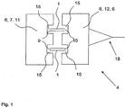
Fig. 1 is a highly simplified longitudinal section through a ventilator having two modules, -
Fig. 2 is a highly simplified longitudinal section through an anaesthetic machine having four modules, -
Fig. 3 is a longitudinal section through a first embodiment of connecting tube in a recess in a second module, -
Fig. 4 is a longitudinal section through a second embodiment of connecting tube in the recess in the second module, -
Fig. 5 is a longitudinal section through a third embodiment of connecting tube in the recess in the second module, -
Fig. 6a is a detailed longitudinal section, showing dimensions, through a connecting tube and two modules in a first possible assembly, -
Fig. 6b is a longitudinal section through two connecting tubes and a first and second module in a possible first assembly, -
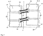
Fig. 7 is a longitudinal section through two connecting tubes and the first and second modules in a possible second assembly, -
Fig. 8 is a longitudinal section through two connecting tubes and the first and second modules in a possible third assembly, -
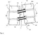
Fig. 9 is a longitudinal section through two connecting tubes and the first and second modules in a possible fourth assembly, -
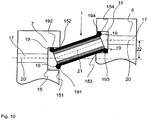
Fig. 10 is a longitudinal section through two connecting tubes and the first and second modules in a possible fifth assembly. - A
ventilator 4 is shown in a highly simplified form inFig. 1 . Theventilator 4 comprises two modules 6, namely a first module 7 and asecond module 8. The two modules 6 are connected together pneumatically in this case by two connectingtubes 1. Each module 6 has tworecesses 15 in this case in which respective ends 9, 10 of the connectingtube 1 are arranged. The first module 7 represents a turbine 11 in this case and thesecond module 8 represents a breathing system 12 in this case. Connected to the breathing system 12 is abreathing hose 18. - In a similar way to
Fig. 1 ,Fig. 2 shows ananaesthetic machine 5. Theanaesthetic machine 5 comprises in this case four modules 6 which, in a similar way to what is done in the first embodiment shown inFig. 1 , are connected together pneumatically by means of connectingtubes 1. The connectingtubes 1 are arranged at each of theirends recesses 15 in the four modules 6 of theanaesthetic machine 5 in this case. As well as the turbine 11 and breathing system 12, theanaesthetic machine 5 comprises in this case a mixer 13 and an anaesthetic vaporiser 14. The anaesthetic vaporiser 14 can be connected to an anaesthetic metering unit by a connecting line (not shown). Connected to the breathing system 12 is the breathinghose 18 for maintaining the patient's respiration artificially. - Shown in
Figs. 3 to 5 are three different embodiments of connectingtube 1. Only thesecond module 8 is shown inFigs. 3 to 5 in this case. The first module 7 is not shown inFigs. 3 to 5 . Also shown is a line ofsymmetry 20 about which theair duct 17 in thesecond module 8 is axially symmetrical and a line ofsymmetry 21 about which the connectingtube 1 is axially symmetrical. Where theair duct 17 in thesecond module 8 is aligned in the way shown in a straight line with the connectingtube 1, the lines ofsymmetry - In the first embodiment of connecting
tube 1 which is shown inFig. 3 , the connectingtube 1 has anouter tube 2 of an elastic outer material and aninner tube 3 of a non-elastic inner material. Theouter tube 2 is fastened in this case to theinner tube 3 by a physical union by being vulcanised thereto. The connectingtube 1 has afirst end 9 and asecond end 10. Thesecond end 10 of the connectingtube 1 is arranged in this case in therecess 15 in thesecond module 8. Formed at the first and seconds ends 9, 10 of the connectingtube 1 in this case is a sealingbead 19 of the outer material, namely the elastomer, which extends round in a loop. The connectingtube 1 is circular in cross-section and therecess 15 constitutes a bore which is circular in cross-section. The external cross-sectional shape of thesecond end 10 of the connectingtube 1, namely in particular the sealingbead 19 at thesecond end 10, thus corresponds to the cross-sectional shape of therecess 15 which is circular in cross-section. When the connectingtube 1 is introduced into therecess 15, a sealingarea 16 extending round in a complete loop can thus be produced between the sealingbead 19 and thesecond module 8 at therecess 15. - In a state where the connecting
tube 1 is not inserted in therecess 15, the sealingbead 19 is slightly larger than therecess 15 and, due to its elastic properties, the sealingbead 19 is thus deformed elastically when it is inserted in therecess 15, i.e. the circumference of the sealingbead 19 is made smaller. The sealingbead 19 is thus arranged in therecess 15 under a pre-loading and a secure and reliable seal is thus ensured between the sealingbead 19 and thesecond module 8 at therecess 15 due to the compressive forces which come into play. Inaccuracies in production at the connectingtube 1 and therecess 15 can also be compensated for in this way. Thefirst end 9 of the connectingtube 1 is also arranged, in a similar way to thesecond end 10, in arecess 15 in the first module 7, although this is not shown. From thesecond module 8 for example, the air is thus able to flow through anair duct 17 in thesecond module 8, then through the connectingtube 1, i.e. through the space connected by theinner tube 3, and then into anair duct 17 in the first module 7 (not shown), as shown inFig. 3 . Due to its geometry and its arrangement in therecess 15, the sealingbead 19 in the first embodiment shown inFig. 3 makes it possible for the connectingtube 1 to be sealed off radially from thesecond module 8 at therecess 15. - The second embodiment of connecting
tube 1 shown inFig. 4 differs from the first embodiment thereof merely in the geometry of the sealingbead 19. In this case the sealingbead 19 is made longer outwards in the axial direction than theinner tube 3, thus enabling not only aradial sealing area 16 but also anaxial sealing area 16 to be produced by means of the sealingbead 19. Otherwise, the second embodiment corresponds to the first embodiment shown inFig. 3 . Elements in the second embodiment inFig. 4 which are the same as in the first embodiment shown inFig. 1 have been given the same reference numerals as inFig. 1 . - The third embodiment shown in
Fig. 5 once again differs from the first embodiment shown inFig. 3 merely in the geometry of the sealingbead 19. The sealingbead 19 is made longer in the axial direction than theinner tube 3 and is offset inwards radially relative thereto, thus enabling only anaxial sealing area 16 to be produced in therecess 15 by means of the sealingbead 19. Otherwise, the third embodiment of connectingtube 1 shown inFig. 5 corresponds to the first embodiment thereof shown inFig. 3 . Elements in the third embodiment inFig. 5 which are the same as in the first embodiment shown inFig. 1 have been given the same reference numerals as inFig. 1 . - Shown in
Figs. 6 to 10 are five different situations for the assembly of a first andsecond module 7, 8 using in each case two connectingtubes 1. The connectingtubes 1, having sealingbeads 19, are arranged in therecesses 15 in themodules 6, 7, 8 and connect theair ducts 17 in themodules 6, 7, 8 together. Shown inFigs. 6 to 10 are lines ofsymmetry air ducts 17 in themodules 6, 7, 8 and the connectingtube 1 are respectively axially symmetrical, to make clearer, in detail, the positions of themodules 6, 7, 8 relative to one another and the positions of themodules 6, 7, 8 relative to the connectingtubes 1. - To allow things to be shown in detail, only a single connecting
tube 1 is shown in the arrangement shown inFig. 6a , with the arrangement comprising the first module 7 and thesecond module 8 connected in a straight line with no vertical or angular offset in the positioning of themodules 7, 8 relative to one another. The sealingbeads 19 form a seal in therecesses 15 in such a way that there is a gas-tight connection between theair ducts 17 in the first andsecond modules 7, 8. What are shown by way of example inFig. 6a , in a representation which is not to scale, are the situations in space of a connectingtube 1, module 6, sealingbead 19,air duct 17 andrecess 15. - In the vertical position, the connecting
tube 1 is fitted into therecess 15, of aheight 26, in each of the modules 6 at its maximum outside diameter comprising thediameter 28 of the connectingtube 1 and thethickness 29 of the sealingbead 19. Along itslength 25, the connectingtube 1 is fitted into recesses of adepth 24 to a depth ofinsertion 27 with the connectingtube 1 in a horizontal position in therecess 15. To illustrate a connection of the modules 6 by means of a connectingtube 1, thelength 25 of the pipe may be sized at 35 mm, thedepth 26 of the recesses may be sized at 11 mm and the depth ofinsertion 27 may be at 5 mm in such a way that the connectingtube 1 fits into therecess 15 in a central position horizontally. Theheight 24 of the recess may be sized at 14 mm such that the connectingtube 1 fits into therecess 15 with a seal if thediameter 28 of the pipe is 10 mm and the thickness of the sealing bead is 2.1 to 2.4 mm. - In the view shown in
Fig. 6b , there is no tolerance between the first module 7 and thesecond module 8, i.e. there is no vertical or angular offset in their geometrical arrangement relative to one another. A connection made by two connectingtubes 1 is shown. There is a secure and reliable pneumatic connection between the first module 7 and thesecond module 8. - In the possible assembly shown in
Fig. 7 , thesecond module 8 is arranged at a slightly higher level than the first module 7, i.e. there is thus a vertical offset 22 between thesecond module 8 and the first module 7. The connection shown is one made with two connectingtubes 1. Due to the elastic nature of the sealingbead 19, this possible assembly too makes a secure and reliable pneumatic connection possible between the first module 7 and thesecond module 8. - In
Fig. 8 there is an angular offset 23 between the first module 7 and thesecond module 8. What this means is that the distance between the first andsecond modules 7, 8 is less at the top than it is between the first andsecond modules 7, 8 at the bottom. The connection shown is one made with two connectingtubes 1. With this situation for installation or possible assembly too, there is an assurance of a reliable pneumatic connection between the first andsecond modules 7, 8. - In a fourth possible assembly which is shown in
Fig. 9 , there is both a vertical offset 22 and an angular offset 23 between the first andsecond modules 7, 8. The connection shown is one made with two connectingtubes 1. The distance between the first andsecond modules 7, 8 is smaller at the top than at the bottom in this case and thesecond module 8 is also arranged at a slightly higher level than the first module 7. With this possible assembly too, there is a reliable pneumatic connection between the first andsecond modules 7, 8. - In the fifth possible assembly shown in
Fig. 10 , a version in which there is an excessive vertical offset 22 is shown to illustrate the limits set by the structure for connecting a first module 7 to asecond module 8. The distance between the first andsecond modules 7, 8 is smaller at the top than at the bottom in this case. At the same time, thesecond module 8 is arranged is arranged in this case at a more than just slightly higher level than the first module 7. To emphasise the details of the arrangement, a connection made with only one connectingtube 1 is shown in which the arrangement is also being asked to do too much structurally, i.e. the vertical offset 22 can no longer be compensated for. Points ofcontact recesses 15 and points ofcontact beads 19 are shown and it can be seen from the positions of these relative to one another whether a sealed connection is possible. It can be seen that, at least at the point ofcontact 153 in therecess 15 in thesecond module 8, the connectingtube 1 is in a tipped position and has an overlap with the second module and that the connectingtube 1 can no longer be fitted into therecess 15 without the connecting tube and/or thesecond module 8 being deformed mechanically. The result of this is that the connectingtube 1 can no longer make contact with a seal in therecess 19 in the first module 7, at least at the point ofcontact 191 by the sealingbead 19. The plug-in connection as a whole is thus no longer gas-tight. With a connection of this particular layout, a reliable pneumatic connection between the first andsecond modules 7, 8 is thus not made by the connectingtube 1 which is used, because the geometry of the connectingtube 1 is not adapted to the positions of themodules 6, 7, 8 and the distance between them. - The first, second, third and fourth possible assemblies or situations for installation show that a secure and reliable pneumatic connection can be made between the first and
second modules 7, 8 with the help of the connectingtubes 1 when there are slight differences in the dimensional accuracy of the components or when there is a difference in their structural symmetry and in particular when there is a vertical offset 22 and/or an angular offset 23 relative to one another between the first andsecond modules 7, 8. - The fifth possible assembly shows the limits set by the structure at which a reliable pneumatic connection cannot be made between the first and
second modules 7, 8. - A secure and reliable pneumatic connection between two modules 6 of a ventilator or
anaesthetic machine tube 1.Appropriate recesses 15 merely have to be formed in the modules 6 of the ventilator oranaesthetic machine tube 1 simply has to be inserted in theserecesses 15. The pneumatic connection can thus easily be made by a plug-in action and can also be disconnected very easily, which is an advantage particularly when maintenance work is being done on the ventilator oranaesthetic machine - The
length 25 of the connectingtube 1 ranges from 25 mm to 35 mm for example and itsoutside diameter 28 is approximately 8 mm to 12 mm for example and itsoutside diameter 28 is preferably 10 mm. As a departure from this, thelength 25 of the connectingtube 1 may range from 10 mm to 40 mm for example and its diameter may range from 5 mm to 15 mm for example. Thelength 25 will be governed essentially by the intended structural distance between the modules 6. Thethickness 29 of the sealing bead will be governed by the elasticity and deformability of the elastic material of the sealing bead and will range from 1 mm to 5 mm. If a fluoro rubber is selected as the elastic outer material and the elastic material of the sealing bead, then a thickness of approximately 2 mm for example is advantageous for the sealing bead. - The
height 26 anddepth 24 of therecess 15 are selected in such a way that there is, within wide limits in the given situations for assembly and with the interaction between thelength 25 of the tube, the material of the sealing beads and thethickness 29 of the sealing beads, a secure, gas-tight, pneumatic connection. - The geometry or size of the connecting
tube 1 relative to therecess 15 may also be designed in this case in such a way that there is no risk at the time of assembly of a mistake or of mis-insertion inunintended recesses 15 in a module 6. - Seen overall, there are considerable advantages to the ventilator or
anaesthetic machine anaesthetic machine anaesthetic machine
Claims (15)
- A ventilator or anaesthetic machine (4, 5) which comprises at least two modules (6, 7, 8), at least one pneumatic connecting means connecting the two modules (6, 7, 8) pneumatically, and wherein :the at least one pneumatic connecting means comprises a connecting tube (1) which is surrounded by the first module (7) at a first end (9) and by the second module (8) at a second end (10), a pneumatic connection thus being made between the first module (7) and the second module (8) by the connecting tube (1);the first and second module (7, 8) each have a recess (15), and the first end (9) of the connecting tube (1) is arranged in the recess (15) in the first module (7) and the second end (10) of the connecting tube (1) is arranged in the recess (15) in the second module (8);a first elastic sealing bead (19) is formed at the first end (9) of the connecting tube (1) and a second elastic sealing bead (19) is formed at the second end (10) of the connecting tube (1), and the first elastic sealing bead (19) is in contact with the first module (7) and the second elastic sealing bead (19) is in contact with the second module (8), a first sealing area (16) thus being formed between the first elastic sealing bead (19) and the first module (8) and a second sealing area (16) thus being formed between the second elastic sealing bead (19) and the second module (8).
- The ventilator or anaesthetic machine according to claim 1, in which the connecting tube (1) is a separate component.
- The ventilator anaesthetic machine according to claim 1 or 2, in which the connecting tube (1) is not a bendable hose.
- The ventilator or anaesthetic machine according to any of claims 1 to 3, in which the connecting tube (1) is connected to the first module (7) by a frictional or positively interengaging connection.
- The ventilator or anaesthetic machine according to any of claims 1 to 4, in which the connecting tube (1) is connected to the second module (8) by frictional or positively interengaging connection.
- The ventilator or anaesthetic machine according to any one of the preceding claims, in which the connecting tube (1) comprises a corrosion-resistant metal on the inside, and an elastic outer material on the outside.
- The ventilator or anaesthetic machine according to claim 6, in which the corrosion-resistant metal is stainless steel.
- The ventilator or anaesthetic machine according to any of claims 1 to 5, in which the connecting tube (1) comprises a plastics material on the inside and an elastic outer material on the outside, and in which the plastics material is a polyether ether ketone .
- The ventilator or anaesthetic machine according to any of claims 6 to 8, in which the elastic outer material is a fluoro rubber, a perfluoro rubber or an ethylene propylene rubber.
- The ventilator or anaesthetic machine according to any one of claim 6 to 9, and in which the sealing bead (19) is formed using the outer material.
- The ventilator or anaesthetic machine according to any one of the preceding claims, in which the connecting tube (1) is circular in cross-section.
- The ventilator or anaesthetic machine according to any preceding claim, in which the cross-sectional shape of the recess (15) in the first module (7) and/or the second module (8) corresponds to the external cross-sectional shape of the connecting tube (1) at the first and/or second end of the connecting tube (1), respectively.
- The ventilator or anaesthetic machine according to any preceding claim, in which, the cross-sectional shape of the recess (15) in the first module (7) corresponds to the external cross-sectional shape the sealing bead (19).
- The ventilator or anaesthetic machine according to any preceding claim, in which, in a state where it is not inserted in the recess (15) in the modules (6, 7, 8), the first end (9) and/or second end (10) of the connecting tube (1), and its sealing bead (19), is formed to be slightly larger than the recess (15) in the modules (6, 7, 8), thus causing the first end (9) of the connecting tube (1) to be arranged in the recess (15) in the modules (6, 7, 8) under a pre-loading.
- The ventilator or anaesthetic machine according to any preceding claim including at least one module selected from the group consisting of a turbine, a breathing system, a mixer and an anaesthetic vaporiser.
Applications Claiming Priority (1)
| Application Number | Priority Date | Filing Date | Title |
|---|---|---|---|
| DE102010004527A DE102010004527A1 (en) | 2010-01-14 | 2010-01-14 | Ventilation and anesthesia machine |
Publications (2)
| Publication Number | Publication Date |
|---|---|
| EP2345448A1 EP2345448A1 (en) | 2011-07-20 |
| EP2345448B1 true EP2345448B1 (en) | 2018-07-25 |
Family
ID=44009825
Family Applications (1)
| Application Number | Title | Priority Date | Filing Date |
|---|---|---|---|
| EP11150286.0A Active EP2345448B1 (en) | 2010-01-14 | 2011-01-06 | Ventilator device or anaesthetic device |
Country Status (4)
| Country | Link |
|---|---|
| US (1) | US20110168176A1 (en) |
| EP (1) | EP2345448B1 (en) |
| CN (1) | CN102188768A (en) |
| DE (1) | DE102010004527A1 (en) |
Families Citing this family (4)
| Publication number | Priority date | Publication date | Assignee | Title |
|---|---|---|---|---|
| CN103182133A (en) * | 2011-12-30 | 2013-07-03 | 北京谊安医疗系统股份有限公司 | Method and structural component for realizing continuous positive airway pressure mode on anaesthesia machine or respirator |
| FR3021388B1 (en) * | 2014-05-21 | 2017-02-17 | Renault Sa | "ASSEMBLY HYDRAULIC ASSEMBLY HAVING PERFECTED SEALING" |
| EP3393571B1 (en) | 2016-02-17 | 2024-03-06 | ClearPoint Neuro, Inc. | Intrabody surgical fluid transfer assemblies with adjustable exposed cannula to needle tip length, related systems and methods |
| US11684750B2 (en) * | 2019-10-08 | 2023-06-27 | Clearpoint Neuro, Inc. | Extension tube assembly and related medical fluid transfer systems and methods |
Citations (1)
| Publication number | Priority date | Publication date | Assignee | Title |
|---|---|---|---|---|
| US5106129A (en) * | 1990-10-09 | 1992-04-21 | Delaware Capital Formation, Inc. | Flexible coupling for transferring a fluid between two fluid conduits |
Family Cites Families (20)
| Publication number | Priority date | Publication date | Assignee | Title |
|---|---|---|---|---|
| BE693426A (en) * | 1966-02-09 | 1967-07-03 | ||
| US3394954A (en) | 1966-05-06 | 1968-07-30 | Sarns Inc | Tube coupling for medical appliances |
| US3968552A (en) * | 1974-10-24 | 1976-07-13 | Hunter John J | Method and apparatus for forming plastic lined junction in lined pipe |
| US4135741A (en) * | 1977-10-11 | 1979-01-23 | Corning Glass Works | Armored piping system |
| DE3048223C2 (en) * | 1980-12-20 | 1984-10-31 | Erich Prof.Dr.med. 8520 Erlangen Rügheimer | Connection system for gas lines with interlocking connecting elements for ventilation or anesthesia devices |
| US4870961A (en) | 1986-09-22 | 1989-10-03 | Barnard Gordon D | Medical ventilator tube and manifold assembly |
| US5027809A (en) * | 1990-05-17 | 1991-07-02 | Robinson Pat D | "Peeper" performance hand held nebuilizer attachment with adjustability of expiratory pressures and expiratory restriction |
| DE69322826T2 (en) * | 1992-09-30 | 1999-06-10 | Tokai Rubber Industries, Ltd., Komaki, Aichi | Multi-layer hose |
| US5354104A (en) * | 1993-01-15 | 1994-10-11 | Techlam | Flexible coupling for pipework |
| US6293311B1 (en) * | 1998-05-22 | 2001-09-25 | Pmd Holdings Corp. | Multilayer composite pipe fluid conduit system using multilayer composite pipe and method of making the composite |
| EP1245377B1 (en) * | 2001-03-28 | 2005-07-20 | Rasmussen GmbH | Multilayered fluid conduit for use in vehicles |
| DE10143290B4 (en) * | 2001-09-04 | 2006-02-09 | Esser-Werke Kg | Arcuate double layer pipe |
| US7506899B2 (en) * | 2003-03-20 | 2009-03-24 | Rain Bird Corporation | Multi-diameter tube fitting |
| DE10312881B3 (en) * | 2003-03-22 | 2004-05-06 | Drägerwerk AG | Respiration hose for medical respiration apparatus incorporating signal line for signal transmission between sensor device and respiration apparatus at its opposite ends |
| US6905144B2 (en) * | 2003-07-02 | 2005-06-14 | Delaware Capital Formation | Spring-loaded ‘L’-shaped seal ring |
| DE202004002665U1 (en) * | 2004-02-20 | 2004-09-02 | Suevia Haiges Gmbh | Impregnation device with a heating device |
| DE102006034028B4 (en) * | 2005-08-01 | 2025-07-10 | Löwenstein Medical Technology S.A. | Ventilation device |
| WO2007051230A1 (en) * | 2005-10-31 | 2007-05-10 | Resmed Ltd | Sensing cuff for breathing apparatus |
| US20070163600A1 (en) * | 2006-01-11 | 2007-07-19 | Leslie Hoffman | User interface and head gear for a continuous positive airway pressure device |
| DE102006053857B3 (en) * | 2006-11-14 | 2007-08-16 | Dräger Medical AG & Co. KG | Respiratory tubing connection device for connecting respiratory tubing to a respiratory device has a main body, an enveloping body, a respiratory gas through-channel and link to a respiratory device |
-
2010
- 2010-01-14 DE DE102010004527A patent/DE102010004527A1/en not_active Ceased
- 2010-12-30 US US12/981,804 patent/US20110168176A1/en not_active Abandoned
-
2011
- 2011-01-06 EP EP11150286.0A patent/EP2345448B1/en active Active
- 2011-01-14 CN CN2011100221886A patent/CN102188768A/en active Pending
Patent Citations (1)
| Publication number | Priority date | Publication date | Assignee | Title |
|---|---|---|---|---|
| US5106129A (en) * | 1990-10-09 | 1992-04-21 | Delaware Capital Formation, Inc. | Flexible coupling for transferring a fluid between two fluid conduits |
Also Published As
| Publication number | Publication date |
|---|---|
| US20110168176A1 (en) | 2011-07-14 |
| CN102188768A (en) | 2011-09-21 |
| DE102010004527A1 (en) | 2011-07-21 |
| EP2345448A1 (en) | 2011-07-20 |
Similar Documents
| Publication | Publication Date | Title |
|---|---|---|
| US11701485B2 (en) | Catheter mount with suction port | |
| EP2345448A1 (en) | Ventilator or anaesthetic machine | |
| US20120227736A1 (en) | Respiratory system connector | |
| CN103357097B (en) | Tracheostomy tube | |
| BR112013006931A2 (en) | methods, systems and devices for respiratory tract humidification | |
| US20140034048A1 (en) | Compressible connector for an inner cannula | |
| US20120247478A1 (en) | Tracheostomy tube assemblies having spherical bearing elements | |
| CN104010570A (en) | Respiratory measuring device with integrated filter | |
| US20140238389A1 (en) | Compressible cannula connector with release grip | |
| CN204479255U (en) | The leak test system of coaxial breathing hose leak test, Connection Element and assembly | |
| JP5616221B2 (en) | Electropneumatic assembly for use in respiratory measurement systems | |
| CN104841049B (en) | Improve trachea cannula | |
| CN109237171A (en) | Deflectable pipeline seal switching device | |
| CN218129518U (en) | Tubing components, air pressure detection modules, nebulization systems and ventilators | |
| CN202554701U (en) | Multi-function noninvasive ventilating face shield | |
| JP3255511U (en) | Anesthesia gas conduit assembly | |
| EP1767182A1 (en) | Member for confirming position of catheter in body and catheter enabling confirmation of its position in body | |
| CN201008699Y (en) | Disposable catheter | |
| CN224056418U (en) | Breathing pipeline | |
| CN204428568U (en) | Assembly is in charge of in salable detection | |
| CN105582606B (en) | Lung ventilator and its air-channel system bindiny mechanism | |
| US20240173509A1 (en) | Probe for gas supply system | |
| US20250025277A1 (en) | Apparatus for attaching intubated non-human animal to gas delivery system | |
| CN219354954U (en) | Connector of respiratory assistance system | |
| CN205108631U (en) | Well minute pipe assembly with joint formula coupling |
Legal Events
| Date | Code | Title | Description |
|---|---|---|---|
| PUAI | Public reference made under article 153(3) epc to a published international application that has entered the european phase |
Free format text: ORIGINAL CODE: 0009012 |
|
| AK | Designated contracting states |
Kind code of ref document: A1 Designated state(s): AL AT BE BG CH CY CZ DE DK EE ES FI FR GB GR HR HU IE IS IT LI LT LU LV MC MK MT NL NO PL PT RO RS SE SI SK SM TR |
|
| AX | Request for extension of the european patent |
Extension state: BA ME |
|
| 17P | Request for examination filed |
Effective date: 20111218 |
|
| 17Q | First examination report despatched |
Effective date: 20150626 |
|
| RAP1 | Party data changed (applicant data changed or rights of an application transferred) |
Owner name: DRAEGERWERK AG & CO. KGAA |
|
| RIC1 | Information provided on ipc code assigned before grant |
Ipc: A61M 16/08 20060101AFI20180202BHEP |
|
| GRAP | Despatch of communication of intention to grant a patent |
Free format text: ORIGINAL CODE: EPIDOSNIGR1 |
|
| STAA | Information on the status of an ep patent application or granted ep patent |
Free format text: STATUS: GRANT OF PATENT IS INTENDED |
|
| INTG | Intention to grant announced |
Effective date: 20180316 |
|
| RIN1 | Information on inventor provided before grant (corrected) |
Inventor name: REICHERT, DIRK-STEFAN Inventor name: KHOLTCHANSKI, GRIGORY Inventor name: PASDZIOR, SVEN Inventor name: LISCHINSKI, ROBERT Inventor name: RADOMSKI, KLAUS |
|
| GRAS | Grant fee paid |
Free format text: ORIGINAL CODE: EPIDOSNIGR3 |
|
| GRAA | (expected) grant |
Free format text: ORIGINAL CODE: 0009210 |
|
| STAA | Information on the status of an ep patent application or granted ep patent |
Free format text: STATUS: THE PATENT HAS BEEN GRANTED |
|
| AK | Designated contracting states |
Kind code of ref document: B1 Designated state(s): AL AT BE BG CH CY CZ DE DK EE ES FI FR GB GR HR HU IE IS IT LI LT LU LV MC MK MT NL NO PL PT RO RS SE SI SK SM TR |
|
| REG | Reference to a national code |
Ref country code: GB Ref legal event code: FG4D |
|
| RIN1 | Information on inventor provided before grant (corrected) |
Inventor name: RADOMSKI, KLAUS Inventor name: REICHERT, DIRK-STEFAN Inventor name: KHOLTCHANSKI, GRIGORY Inventor name: LISCHINSKI, ROBERT Inventor name: PASDZIOR, SVEN |
|
| REG | Reference to a national code |
Ref country code: CH Ref legal event code: EP |
|
| REG | Reference to a national code |
Ref country code: AT Ref legal event code: REF Ref document number: 1021096 Country of ref document: AT Kind code of ref document: T Effective date: 20180815 |
|
| REG | Reference to a national code |
Ref country code: IE Ref legal event code: FG4D |
|
| REG | Reference to a national code |
Ref country code: DE Ref legal event code: R096 Ref document number: 602011050283 Country of ref document: DE |
|
| REG | Reference to a national code |
Ref country code: NL Ref legal event code: MP Effective date: 20180725 |
|
| REG | Reference to a national code |
Ref country code: LT Ref legal event code: MG4D |
|
| PG25 | Lapsed in a contracting state [announced via postgrant information from national office to epo] |
Ref country code: NL Free format text: LAPSE BECAUSE OF FAILURE TO SUBMIT A TRANSLATION OF THE DESCRIPTION OR TO PAY THE FEE WITHIN THE PRESCRIBED TIME-LIMIT Effective date: 20180725 |
|
| REG | Reference to a national code |
Ref country code: AT Ref legal event code: MK05 Ref document number: 1021096 Country of ref document: AT Kind code of ref document: T Effective date: 20180725 |
|
| PG25 | Lapsed in a contracting state [announced via postgrant information from national office to epo] |
Ref country code: PL Free format text: LAPSE BECAUSE OF FAILURE TO SUBMIT A TRANSLATION OF THE DESCRIPTION OR TO PAY THE FEE WITHIN THE PRESCRIBED TIME-LIMIT Effective date: 20180725 Ref country code: FI Free format text: LAPSE BECAUSE OF FAILURE TO SUBMIT A TRANSLATION OF THE DESCRIPTION OR TO PAY THE FEE WITHIN THE PRESCRIBED TIME-LIMIT Effective date: 20180725 Ref country code: LT Free format text: LAPSE BECAUSE OF FAILURE TO SUBMIT A TRANSLATION OF THE DESCRIPTION OR TO PAY THE FEE WITHIN THE PRESCRIBED TIME-LIMIT Effective date: 20180725 Ref country code: RS Free format text: LAPSE BECAUSE OF FAILURE TO SUBMIT A TRANSLATION OF THE DESCRIPTION OR TO PAY THE FEE WITHIN THE PRESCRIBED TIME-LIMIT Effective date: 20180725 Ref country code: SE Free format text: LAPSE BECAUSE OF FAILURE TO SUBMIT A TRANSLATION OF THE DESCRIPTION OR TO PAY THE FEE WITHIN THE PRESCRIBED TIME-LIMIT Effective date: 20180725 Ref country code: GR Free format text: LAPSE BECAUSE OF FAILURE TO SUBMIT A TRANSLATION OF THE DESCRIPTION OR TO PAY THE FEE WITHIN THE PRESCRIBED TIME-LIMIT Effective date: 20181026 Ref country code: AT Free format text: LAPSE BECAUSE OF FAILURE TO SUBMIT A TRANSLATION OF THE DESCRIPTION OR TO PAY THE FEE WITHIN THE PRESCRIBED TIME-LIMIT Effective date: 20180725 Ref country code: NO Free format text: LAPSE BECAUSE OF FAILURE TO SUBMIT A TRANSLATION OF THE DESCRIPTION OR TO PAY THE FEE WITHIN THE PRESCRIBED TIME-LIMIT Effective date: 20181025 Ref country code: IS Free format text: LAPSE BECAUSE OF FAILURE TO SUBMIT A TRANSLATION OF THE DESCRIPTION OR TO PAY THE FEE WITHIN THE PRESCRIBED TIME-LIMIT Effective date: 20181125 Ref country code: BG Free format text: LAPSE BECAUSE OF FAILURE TO SUBMIT A TRANSLATION OF THE DESCRIPTION OR TO PAY THE FEE WITHIN THE PRESCRIBED TIME-LIMIT Effective date: 20181025 |
|
| PG25 | Lapsed in a contracting state [announced via postgrant information from national office to epo] |
Ref country code: HR Free format text: LAPSE BECAUSE OF FAILURE TO SUBMIT A TRANSLATION OF THE DESCRIPTION OR TO PAY THE FEE WITHIN THE PRESCRIBED TIME-LIMIT Effective date: 20180725 Ref country code: LV Free format text: LAPSE BECAUSE OF FAILURE TO SUBMIT A TRANSLATION OF THE DESCRIPTION OR TO PAY THE FEE WITHIN THE PRESCRIBED TIME-LIMIT Effective date: 20180725 Ref country code: ES Free format text: LAPSE BECAUSE OF FAILURE TO SUBMIT A TRANSLATION OF THE DESCRIPTION OR TO PAY THE FEE WITHIN THE PRESCRIBED TIME-LIMIT Effective date: 20180725 Ref country code: AL Free format text: LAPSE BECAUSE OF FAILURE TO SUBMIT A TRANSLATION OF THE DESCRIPTION OR TO PAY THE FEE WITHIN THE PRESCRIBED TIME-LIMIT Effective date: 20180725 |
|
| REG | Reference to a national code |
Ref country code: DE Ref legal event code: R097 Ref document number: 602011050283 Country of ref document: DE |
|
| PG25 | Lapsed in a contracting state [announced via postgrant information from national office to epo] |
Ref country code: CZ Free format text: LAPSE BECAUSE OF FAILURE TO SUBMIT A TRANSLATION OF THE DESCRIPTION OR TO PAY THE FEE WITHIN THE PRESCRIBED TIME-LIMIT Effective date: 20180725 Ref country code: IT Free format text: LAPSE BECAUSE OF FAILURE TO SUBMIT A TRANSLATION OF THE DESCRIPTION OR TO PAY THE FEE WITHIN THE PRESCRIBED TIME-LIMIT Effective date: 20180725 Ref country code: RO Free format text: LAPSE BECAUSE OF FAILURE TO SUBMIT A TRANSLATION OF THE DESCRIPTION OR TO PAY THE FEE WITHIN THE PRESCRIBED TIME-LIMIT Effective date: 20180725 Ref country code: EE Free format text: LAPSE BECAUSE OF FAILURE TO SUBMIT A TRANSLATION OF THE DESCRIPTION OR TO PAY THE FEE WITHIN THE PRESCRIBED TIME-LIMIT Effective date: 20180725 |
|
| PG25 | Lapsed in a contracting state [announced via postgrant information from national office to epo] |
Ref country code: DK Free format text: LAPSE BECAUSE OF FAILURE TO SUBMIT A TRANSLATION OF THE DESCRIPTION OR TO PAY THE FEE WITHIN THE PRESCRIBED TIME-LIMIT Effective date: 20180725 Ref country code: SK Free format text: LAPSE BECAUSE OF FAILURE TO SUBMIT A TRANSLATION OF THE DESCRIPTION OR TO PAY THE FEE WITHIN THE PRESCRIBED TIME-LIMIT Effective date: 20180725 Ref country code: SM Free format text: LAPSE BECAUSE OF FAILURE TO SUBMIT A TRANSLATION OF THE DESCRIPTION OR TO PAY THE FEE WITHIN THE PRESCRIBED TIME-LIMIT Effective date: 20180725 |
|
| PLBE | No opposition filed within time limit |
Free format text: ORIGINAL CODE: 0009261 |
|
| STAA | Information on the status of an ep patent application or granted ep patent |
Free format text: STATUS: NO OPPOSITION FILED WITHIN TIME LIMIT |
|
| 26N | No opposition filed |
Effective date: 20190426 |
|
| PG25 | Lapsed in a contracting state [announced via postgrant information from national office to epo] |
Ref country code: SI Free format text: LAPSE BECAUSE OF FAILURE TO SUBMIT A TRANSLATION OF THE DESCRIPTION OR TO PAY THE FEE WITHIN THE PRESCRIBED TIME-LIMIT Effective date: 20180725 Ref country code: MC Free format text: LAPSE BECAUSE OF FAILURE TO SUBMIT A TRANSLATION OF THE DESCRIPTION OR TO PAY THE FEE WITHIN THE PRESCRIBED TIME-LIMIT Effective date: 20180725 |
|
| REG | Reference to a national code |
Ref country code: CH Ref legal event code: PL |
|
| PG25 | Lapsed in a contracting state [announced via postgrant information from national office to epo] |
Ref country code: LU Free format text: LAPSE BECAUSE OF NON-PAYMENT OF DUE FEES Effective date: 20190106 |
|
| REG | Reference to a national code |
Ref country code: BE Ref legal event code: MM Effective date: 20190131 |
|
| REG | Reference to a national code |
Ref country code: IE Ref legal event code: MM4A |
|
| PG25 | Lapsed in a contracting state [announced via postgrant information from national office to epo] |
Ref country code: BE Free format text: LAPSE BECAUSE OF NON-PAYMENT OF DUE FEES Effective date: 20190131 |
|
| PG25 | Lapsed in a contracting state [announced via postgrant information from national office to epo] |
Ref country code: LI Free format text: LAPSE BECAUSE OF NON-PAYMENT OF DUE FEES Effective date: 20190131 Ref country code: CH Free format text: LAPSE BECAUSE OF NON-PAYMENT OF DUE FEES Effective date: 20190131 |
|
| PG25 | Lapsed in a contracting state [announced via postgrant information from national office to epo] |
Ref country code: IE Free format text: LAPSE BECAUSE OF NON-PAYMENT OF DUE FEES Effective date: 20190106 |
|
| PG25 | Lapsed in a contracting state [announced via postgrant information from national office to epo] |
Ref country code: TR Free format text: LAPSE BECAUSE OF FAILURE TO SUBMIT A TRANSLATION OF THE DESCRIPTION OR TO PAY THE FEE WITHIN THE PRESCRIBED TIME-LIMIT Effective date: 20180725 |
|
| PG25 | Lapsed in a contracting state [announced via postgrant information from national office to epo] |
Ref country code: MT Free format text: LAPSE BECAUSE OF NON-PAYMENT OF DUE FEES Effective date: 20190106 Ref country code: PT Free format text: LAPSE BECAUSE OF FAILURE TO SUBMIT A TRANSLATION OF THE DESCRIPTION OR TO PAY THE FEE WITHIN THE PRESCRIBED TIME-LIMIT Effective date: 20181125 |
|
| PG25 | Lapsed in a contracting state [announced via postgrant information from national office to epo] |
Ref country code: CY Free format text: LAPSE BECAUSE OF FAILURE TO SUBMIT A TRANSLATION OF THE DESCRIPTION OR TO PAY THE FEE WITHIN THE PRESCRIBED TIME-LIMIT Effective date: 20180725 |
|
| PG25 | Lapsed in a contracting state [announced via postgrant information from national office to epo] |
Ref country code: HU Free format text: LAPSE BECAUSE OF FAILURE TO SUBMIT A TRANSLATION OF THE DESCRIPTION OR TO PAY THE FEE WITHIN THE PRESCRIBED TIME-LIMIT; INVALID AB INITIO Effective date: 20110106 |
|
| PG25 | Lapsed in a contracting state [announced via postgrant information from national office to epo] |
Ref country code: MK Free format text: LAPSE BECAUSE OF FAILURE TO SUBMIT A TRANSLATION OF THE DESCRIPTION OR TO PAY THE FEE WITHIN THE PRESCRIBED TIME-LIMIT Effective date: 20180725 |
|
| REG | Reference to a national code |
Ref country code: DE Ref legal event code: R084 Ref document number: 602011050283 Country of ref document: DE |
|
| REG | Reference to a national code |
Ref country code: GB Ref legal event code: 746 Effective date: 20230621 |
|
| PGFP | Annual fee paid to national office [announced via postgrant information from national office to epo] |
Ref country code: GB Payment date: 20260122 Year of fee payment: 16 |
|
| PGFP | Annual fee paid to national office [announced via postgrant information from national office to epo] |
Ref country code: DE Payment date: 20260120 Year of fee payment: 16 |
|
| PGFP | Annual fee paid to national office [announced via postgrant information from national office to epo] |
Ref country code: FR Payment date: 20260128 Year of fee payment: 16 |